

Zoom Corporation 510 Operation Manual
Thank you for selecting the ZOOM 510 (hereafter simply called the "510").
Please take the time to read this manual carefully so you can get the most out of
your 510 and ensure optimum performance and reliability.
Retain this manual for future reference.
ZOOM CORPORATION
NOAH Bldg., 2-10-2, Miyanishi-cho, Fuchu-shi, Tokyo 183, Japan
PHONE: 0423-69-7116 FAX: 0423-69-7115
Printed in Japan 510-5000
• Dedicated distortion unit with two on-board distortion modules (PRE DRIVE and
MAIN DRIVE).
• Parallel or serial connection of distortion modules allows the creation of variations that
are difficult to achieve with conventional multi-effect devices, such as adding light
distortion after strong distortion. The result is a wide variety of overdrive and distortion
sounds.
• Total of 16 effects (eight effect types per distortion module) can be combined . Besides
distortion effects, PRE DRIVE also contains compressor, pedal wah, auto wah, octaver
and other versatile effects.
• You can switch between 24 patches to store diverse settings based on your preference.
• Integrated auto-chromatic tuner for guitar. You can tune your instrument easily
anywhere, any time. You can also leave the tuning function disabled all the time.
• Mixing balance of PRE DRIVE and MAIN DRIVE can be varied according to picking
intensity, using the auto-parallel connection feature. This provides a wide expression
range for solo play.
• Optional expression pedal FP01 can be used to control pedal wah, MAIN DRIVE gain,
mixing balance for parallel connection and other parameters. Optional foot switch FS01
allows switching PRE DRIVE on and off during a performance.
•
Dual power supply design allows the unit to be powered from a 9V alkaline battery
(6LR61) or an AC adapter.
USAGE AND SAFETY PRECAUTIONS
In this manual, symbols are used to highlight warnings and
cautions for you to read so that accidents can be prevented. The
meanings of these symbols are as follows:
Please observe the following safety tips and precautions to ensure
hazard-free use of the 510.
Since power consumption of this unit is fairly high, we
recommend the use of an AC adapter whenever possible.
When powering the unit from a battery, use only an alkaline
type.
AC adapter operation
• Be sure to use only an AC adapter which supplies 9 V DC,
300 mA and is equipped with a "center minus" plug (Zoom
AD-0006). The use of an adapter other than the specified type
may damage the unit and pose a safety hazard.
• Connect the AC adapter only to an AC outlet that supplies the
rated voltage required by the adapter.
• When disconnecting the AC adapter from the AC outlet,
always grasp the adapter itself and do not pull the cable.
• If the unit is not to be used for a long time, disconnect the AC
adapter from the outlet.
Battery operation
• Use only a 9 V (alkaline) battery (6LR61).
• The 510 cannot be used for recharging.
Pay close attention to the labelling of the battery to make sure
you choose the correct type.
• If the 510 is not to be used for an extended period of time,
remove the battery from the unit.
• If battery leakage has occurred, wipe the battery compartment
and the battery terminals carefully to remove all remnants of
battery fluid.
• While using the unit, the battery compartment cover should
be closed.
Avoid using your 510 in environments where it will be
exposed to:
• Extreme temperature
• High humidity or moisture
• Excessive dust or sand
• Excessive vibration or shock
• The 510 is a precision instrument. Except for the foot
switches, do not push other parts with your feet or subject
them to strong force.
• Take care that no foreign objects (coins or pins etc.) or liquids
enter the unit.
• Be sure to turn the power to all equipment off before making
connections.
• Before moving the unit, turn the power off and disconnect all
cables and the AC adapter.
Never open the case of the 510 or attempt to modify the
product in any way since this can result in damage to the unit.
Usage precautions
For safety considerations, the 510 has been designed to provide
maximum protection against the emission of electromagnetic
radiation from inside the device, and from external
interference.However, equipment that is very susceptible to
interference or that emits powerful electromagnetic waves
should not be placed near the 510, as the possibility of
interference cannot be ruled out entirely.
Whatever the type of digital control device, the 510 included,
electromagnetic damage can cause malfunctioning and corrupt
or destroy data. Since this is an ever-present danger, thorough
care should be taken to minimize the risk of damage.
Use a soft, dry cloth to clean the 510. If necessary, slightly
moisten the cloth. Do not use abrasive cleanser, wax, or
solvents (such as paint thinner or cleaning alcohol), since these
may dull the finish or damage the surface.
Connecting cables and input and output jacks
You should always turn off the power to the 510 and all other
equipment before connecting or disconnecting any cables. Also
make sure to disconnect all cables and the AC adapter before
moving the 510.
Major Features
Safety Precautions
Warning
This symbol indicates explanations about extremely
dangerous issues. If users ignore this symbol and handle
the device incorrectly, serious injury or death could
result.
Caution
This symbol indicates explanations about dangerous
issues. If users ignore this symbol and handle the
device the wrong way, bodily injury and damage to the
equipment could result.
Warning
About power
Caution
Environment
Caution
Handling
Caution
Alterations
Electrical interference
Cleaning
1
2
Operation Manual
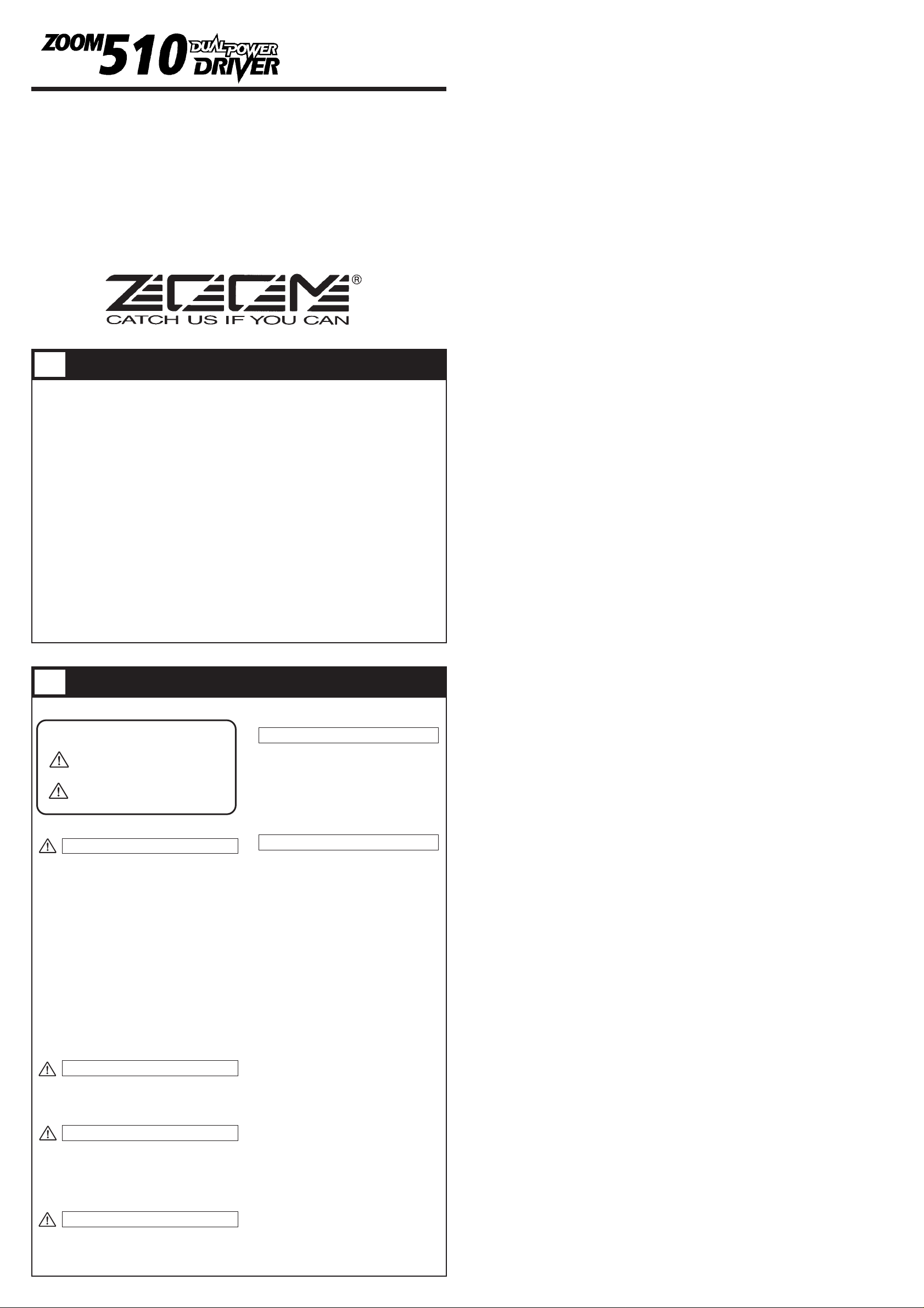
• PATCH
A group of the settings for a certain effect type is called a PATCH. The 510 comes with 24 preset
patches which can be changed (edited) by the user.
• BANK
The 510 calls up patches in sets of four, called a "bank".
The 510 has memory capacity for 24 patches. At the factory, these are programmed with recommended
settings. The user can Edit and Store any patch, and also restore the factory settings.
What Are Banks and Patches? PATCH LIST
Configuration of Effects
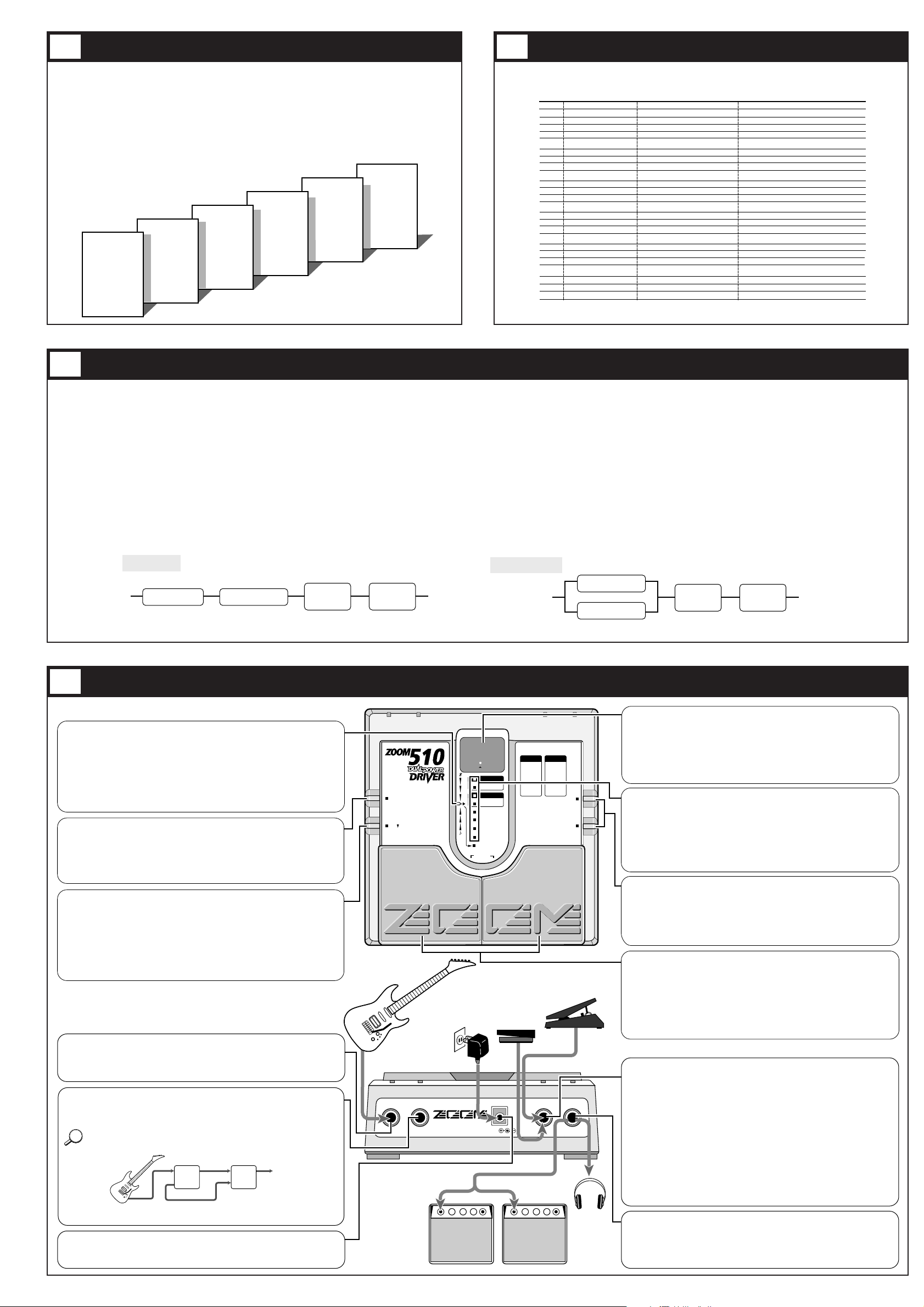
Controls, Functions and Connections
The patches of the 510 are created using the PRE DRIVE, MAIN DRIVE, HIGH/LOW
(equalizer), and ZNR/AMP (Zoom Noise Reduction/Amp Simulator) modules. You can imagine
a module as a box containing various effect settings.
PRE DRIVE and MAIN DRIVE each contain eight effect types, from which you can choose one
at a time. Each effect type in turn is made up of several effect parameters that determine the
sound. Effect parameters can be adjusted, just as you can turn the knobs on a single compact
effect device. A patch is a combination of two effects from the modules, each with their effect
parameters set to certain values.
The effects from PRE DRIVE and MAIN DRIVE can be combined (linked) in two different
ways, as described below. The type of link is also stored as part of the patch.
INPUT
DC 9V
CONTROL IN
OUTPUT
300mA
DIRECT OUT
(PHONES)
ZOOM CORPORATION
MADE IN JAPAN
STORE
TUNER CAL.
EDIT VAL.
BANK
OUTPUT
INPUT
EDIT
UP
DOWN
BYPASS
BANK HOLD
A
1
LOW
HIGH
ZNR
AMP
SERIAL/PARA
LEVEL
+
–
COMPACT MULTI EFFECTS PROCESSOR
1 BOOSTER
2 RHYTHM
3 LIGHT OD
4 DYNAMIC OD
5 COMP
6 AUTO WAH
7 PEDAL WAH
8 OCTAVE
PRE DRIVE
1 OVER DRIVE
2 BLUES OD
3 FAT DRAIVE
4 DISTORTION
5 FUZZ
6 GRUNGE
7 LEAD
8 METAL
MAIN DRIVE
1...9,A1...A9
1...30
-15...15
-15...15
GAIN
1...16
GAIN
Pd,1...30
PRE DRIVE
MAIN DRIVE
HINT
Front Panel
Rear Panel
TUNER indicator
• Bypass/Tuner mode:
Indicator shows that tuning function is active and also serves to show the correct
fine tuning position.
• Edit mode:
Indicator flashes when SERIAL/PARA (Serial/parallel) switching is carried out.
• BATTERY EMPTY WARNING display
When the unit is powered from the battery and the battery is running low, this
indicator begins flashing at a faster rate than in Edit mode. In such a case, replace
the battery as soon as possible.
STORE key
When the contents of patches are to be stored, this key is used for putting the unit in
store standby status and to execute the store function.
• Setting of direct load function
When the STORE key is pressed for at least 1 second during Play mode (during
performance), the direct load function can be switched on or off. [For details, see 10
Patch Switching (Application: Direct Load OFF).]
EDIT key (for creating your own patches)
This key serves to toggle between the Play mode and Edit mode (mode for creating
patches to suit your taste).
In Edit mode, this key can be used to select the effect parameters you wish to
change. Also, when the effect parameter SERIAL/PARA is selected, press this
EDIT key to return from the Edit mode to the Play mode.
• Setting of bank hold function
When the EDIT key is held down for at least 1 second in Play mode, the bank hold
function is turned on or off. [For details, see 9 Patch Switching (Application: Bank
Hold ON).]
INPUT jack
Instrument input.
When the unit is powered by the battery, this jack also functions as the power on/off
switch. The 510 is powered on by plugging a shielded cable into this jack. When the
unit is not in use, the cable should be disconnected to prevent battery drain.
DIRECT OUT jack
Supplies the signal from the INPUT jack without any processing.
Connect to equipment with high input impedance, such as a guitar amplifier or other
effect device.
When the 510 is used together with the DUAL POWER MODULATOR 509, making
the connection as shown below ensures that the HPS (Harmonized Pitch Shifter)
effect of the 509 works correctly.
For details, please refer to the operation manual of the DUAL POWER MODULATOR
509.
DC IN (AC adapter) jack
Serves for connecting an AC adapter (Zoom AD-0006) which delivers 9 VDC, 300
mA with a "center minus" plug configuration. The 510 is powered on by plugging
an AC adapter into this jack.
CONTROL IN jack
The optional foot switch FS01 or expression pedal FP01 can be connected here,
for external control of the 510.
• When the foot switch FS01 is connected:
The PRE DRIVE effect module is switched on and off with the foot switch.
• When the expression pedal FP01 is connected:
The pedal controls a function determined by a parameter of the currently selected
patch, as described below.
(1) Parameter 1 (PRE DRIVE effect type) set to "7" (pedal wah):
Pedal functions as pedal wah.
(2) Parameter 4 (GAIN parameter of MAIN DRIVE) set to "Pd" :
Pedal controls gain of MAIN DRIVE.
(3) Parameter 9 (Serial/parallel switching) set to "Pd" :
Pedal controls mixing balance of PRE DRIVE and MAIN DRIVE modules.
* Functions (1) - (3) can be used simultaneously. For patches where (1) - (3) do not
apply, the pedal serves as volume pedal to control the overall output level.
DISPLAY
Displays information required to operate the 510.
• Play mode
Displays the selected bank (A-F) and patch (1-4).
• Edit mode
Displays the value of the selected effect parameter.
• Bypass/Tuner mode
Shows the pitch of the input signal.
PARAMETER CURSOR indicator
• Play mode
The currently used effect module lights.
• Edit mode
The indicator lights up for the currently used effect module, and the indicator
flashes for the effect module that is turned off. Also, the indicator for the effect
module selected for editing flashes.
• Bypass/Tuner mode
Indicators function as tuning meter.
VALUE +/- keys
• Play mode
The keys serve for bank switching.
• Edit mode
The keys serve for changing the effect parameter.
• Bypass/Tuner mode
The keys serve for setting the tuner reference pitch (calibration).
PATCH UP (right)/DOWN (left) pedals
• Play mode
The pedals serve for patch switching. Pressing both pedals simultaneously
activates the Bypass/Tuner mode.
• Edit mode
The pedals serve for selecting effect parameters. Pressing both pedals
simultaneously turns the currently selected effect module on or off.
• Bypass/Tuner mode
Pressing either pedal cancels the Bypass/Tuner mode to return to Play mode.
OUTPUT jack
This jack is for the output signal from the 510. You can connect either a single
guitar amplifier, using a monaural shielded cable, or two guitar amplifiers, using
a Y-type stereo shielded cable, or a pair of stereo headphones. If the volume level
is low when using headphones, use headphones with low impedance (32 ohms or
less).
INPUT OUTPUT
DIRECT OUT
510 509
INPUT OUTPUT
DETECTOR IN
To amplifier
or other effect device
5
3 4
6
BANK A
PATCH 1
PATCH 2
PATCH 3
PATCH 4
BANK b
PATCH 1
PATCH 2
PATCH 3
PATCH 4
BANK C
PATCH 1
PATCH 2
PATCH 3
PATCH 4
BANK d
PATCH 1
PATCH 2
PATCH 3
PATCH 4
BANK E
PATCH 1
PATCH 2
PATCH 3
PATCH 4
BANK F
PATCH 1
PATCH 2
PATCH 3
PATCH 4
PATCH# PATCH NAME PRE DRIVE MAIN DRIVE
A1
A2
A3
A4
b1
b2
b3
b4
C1
C2
C3
C4
d1
d2
d3
d4
E1
E2
E3
E4
F1
F2
F3
F4
RHYTHM
OFF
COMP
OFF
COMP
RHYTHM
AUTO WAH
OCTAVE
PEDAL WAH
BOOSTER
LIGHT OD
COMP
BOOSTER
RHYTHM
AUTO WAH
DYNAMIC OD
LIGHT OD
LIGHT OD
BOOSTER
COMP
BOOSTER
COMP
AUTO WAH
OCTAVE
DISTORTION
METAL
OVER DRIVE
FUZZ
DISTORTION
OVER DRIVE
OVER DRIVE
OVER DRIVE
FAT DRIVE
DISTORTION
GRUNGE
OVER DRIVE
DISTORTION
BLUES OD
OVER DRIVE
OVER DRIVE
OVER DRIVE
FAT DRIVE
BLUES OD
LEAD
LEAD (Pd)
OVER DRIVE (Pd)
BLUES OD (Pd)
METAL
–
–
–
–
/
–
–
–
–
/
–
–
–
–
/
/
–
–
/
–
–
–
/
–
Multi Drive
Metallic
The Over Drive
FUZZY
Power DIST
Rhythm & Blues
Feelin' Wah
Bass Plus
Violent Wah
Heavy Bottom
GRUNGE!
Hard Drive
The Crunch
Vintage
Crunch Wah
Dynamic OD
OD Line (AMP SIM)
DIST Line (AMP SIM)
Small Box (AMP SIM)
Old-Fashioned (AMP SIM)
Pedal Boost
COMP+DRIVE Mix
WAH ↔ DIST
Metal Octave
COMMENT
Dual distortion sound for all styles
Metal sound for low-note riff
Standard overdrive with comp
Contemporary fuzz sound
Stacking amp simulation
Crunchy overdrive, good for R&B
Wah controlled by picking
Play "Superstition"!
Half-opened pedal wah sound
Heavy drive with bottom tone
High gained grunge drive
"Hard drivin" turbo overdrive
Crunch sound, good for rock & roll
Vintage drive sound, good for blues
Play hard to add wah effect
Touch sensitive drive
Overdrive sound for line connection
Distortion sound for line connection
Small amp simulation for line connection
Old amp simulation for line connection
Main drive can be controlled by using FP01
Use FP01 to add overdrive
Can be changed to overdrive by FP01
Metallic sound, play single note
* In the "PRE DRIVE MAIN DRIVE" column, "–" indicates serial connection and "/" parallel connection.
* ZNR (ZOOM NOISE REDUCUTION) should be adjusted for the guitar you use.
* The OCTAVE effect is not suitable for chord input. To prevent wrong operation, pick only precise single notes.
PRE DRIVE MAIN DRIVE
HIGH
& LOW
ZNR
/AMP
PRE DRIVE
MAIN DRIVE
HIGH
& LOW
ZNR
/AMP
PARALLEL
SERIAL
• SERIAL
PRE DRIVE and MAIN DRIVE are connected in series (one after the other).
For example, PRE DRIVE could first apply light distortion, and then MAIN
DRIVE could add heavy distortion.
• PARALLEL
PRE DRIVE and MAIN DRIVE are connected in parallel (side by side) and
their output is mixed. For example, PRE DRIVE could apply the OCTAVE
effect and MAIN DRIVE the OVERDRIVE effect simultaneously.
 Loading...