

Zoom Corporation 507 Operation Manual
Thank you for selecting the ZOOM 507 (hereafter simply called the "507").
Please take the time to read this manual carefully so you can get the most out of
your 507 and ensure optimum performance and reliability.
Retain this manual for future reference.
ZOOM CORPORATION
NOAH Bldg., 2-10-2, Miyanishi-cho, Fuchu-shi, Tokyo 183, Japan
PHONE: 0423-69-7116 FAX: 0423-69-7115
Printed in Japan 507-5000
• High-grade reverb of top class devices despite compact size; delay with 990
ms maximum delay time; and outstanding spatial effects that produce a
beautiful chorus sound at an affordable price.
• On-board "Zfx-2" DSP (Digital Signal Processor) developed by Zoom, and
an innovative design used solely for its powerful spatial effects.
Demonstrates its power in home recording as well as in live performances.
• You can switch between 24 patches to store diverse settings based on your
preference.
• Integrated auto-chromatic tuner for guitar. You can tune your instrument
easily anywhere, any time. You can also leave the tuning function disabled all
the time.
• The optional FP01 expression pedal enables foot control of the mix level for
the effect sound. The optional FS01 foot switch enables operation of the
chorus ON/OFF switch.
• Dual power supply design allows the unit to be powered from an alkaline
battery (6LR61) or an AC adapter.
USAGE AND SAFETY PRECAUTIONS
In this manual, symbols are used to highlight warnings and
cautions for you to read so that accidents can be prevented. The
meanings of these symbols are as follows:
Please observe the following safety tips and precautions to ensure
hazard-free use of the 507.
• Since power consumption of this unit is fairly high, we
recommend the use of an AC adapter whenever possible.
When powering the unit from a battery, use only an alkaline
type.
AC adapter operation
• Be sure to use only an AC adapter which supplies 9 V DC,
300 mA and is equipped with a "center minus" plug (Zoom
AD-0006). The use of an adapter other than the specified type
may damage the unit and pose a safety hazard.
• Connect the AC adapter only to an AC outlet that supplies the
rated voltage required by the adapter.
• When disconnecting the AC adapter from the AC outlet,
always grasp the adapter itself and do not pull the cable.
• If the unit is not to be used for a long time, disconnect the AC
adapter from the outlet.
Battery operation
• Use only a 9 V (alkaline) battery (6LR61).
• The 507 cannot be used for recharging.
Pay close attention to the labelling of the battery to make sure
you choose the correct type.
• If the 507 is not to be used for an extended period of time,
remove the battery from the unit.
• If battery leakage has occurred, wipe the battery compartment
and the battery terminals carefully to remove all remnants of
battery fluid.
• While using the unit, the battery compartment cover should
be closed.
Avoid using your 507 in environments where it will be
exposed to:
• Extreme temperature
• High humidity or moisture
• Excessive dust or sand
• Excessive vibration or shock
• The 507 is a precision instrument. Except for the foot
switches, do not push other parts with your feet or subject
them to strong force.
• Take care that no foreign objects (coins or pins etc.) or liquids
enter the unit.
• Be sure to turn the power to all equipment off before making
connections.
• Before moving the unit, turn the power off and disconnect all
cables and the AC adapter.
Never open the case of the 507 or attempt to modify the
product in any way since this can result in damage to the unit.
Usage precautions
For safety considerations, the 507 has been designed to provide
maximum protection against the emission of electromagnetic
radiation from inside the device, and from external
interference.However, equipment that is very susceptible to
interference or that emits powerful electromagnetic waves
should not be placed near the 507, as the possibility of
interference cannot be ruled out entirely.
Whatever the type of digital control device, the 507 included,
electromagnetic damage can cause malfunctioning and corrupt
or destroy data. Since this is an ever-present danger, thorough
care should be taken to minimize the risk of damage.
Use a soft, dry cloth to clean the 507. If necessary, slightly
moisten the cloth. Do not use abrasive cleanser, wax, or
solvents (such as paint thinner or cleaning alcohol), since these
may dull the finish or damage the surface.
Connecting cables and input and output jacks
You should always turn off the power to the 507 and all other
equipment before connecting or disconnecting any cables. Also
make sure to disconnect all cables and the AC adapter before
moving the 507.
Major Features
Safety Precautions
Warning
This symbol indicates explanations about extremely
dangerous issues. If users ignore this symbol and handle
the device incorrectly, serious injury or death could
result.
Caution
This symbol indicates explanations about dangerous
issues. If users ignore this symbol and handle the
device the wrong way, bodily injury and damage to the
equipment could result.
Warning
About power
Caution
Environment
Caution
Handling
Caution
Alterations
Electrical interference
Cleaning
1
2
Operation Manual
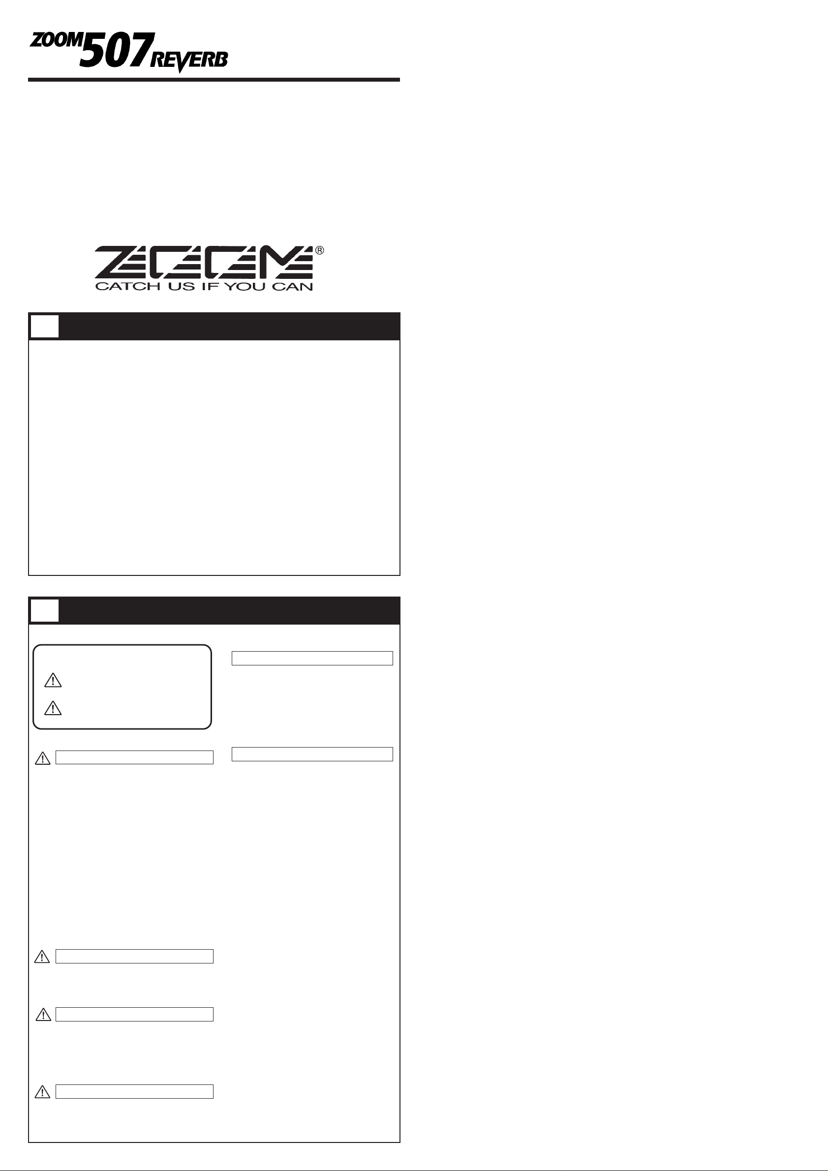
• PATCH
A group of the settings for a certain effect type is called a PATCH. The 507 comes with 24 preset
patches which can be changed (edited) by the user.
• BANK
The 507 calls up patches in sets of four, called a "bank".
The 507 has memory capacity for 24 patches. At the factory, these are programmed with recommended
settings. The user can freely change the contents of any patch, and it is also possible to restore the
factory settings.
What Are Banks and Patches? PATCH LIST
Configuration of Effects
Controls, Functions and Connections
The 507's patches are composed of two effect modules (virtual boxes for making effect settings
easy to understand). These modules contain effect parameters, elements that decide the tones of
the effects. Patches are the parameters set according to taste in the effect modules.
• REVERB/DLY+REV module
This is the module that can be used either as various types of REVERB or DLY+REV,
depending on the parameter setting.
• CHORUS module
This is an effect module that gives the notes a round, expansive feeling. This can be connected
before or after the REVERB/DLY+REV module by setting the parameter accordingly.
When connected after the REVERB/DLY+REV module, the chorus sound is emphasized and a
flanger effect can also be obtained.
OUTPUT
CHORUS
PARAMETER 1
REVERB TYPE
PARAMETER 2
REVERB TIME / DELAY TIME
PARAMETER 3
TONE / FB
PARAMETER 4
REVERB MIX
PARAMETER 5
CHORUS
INPUT
REVERB / DLY+REV
STORE
EDIT
TUNER CAL.
EDIT VAL.
BANK
+
OUTPUT INPUT
ZOOM CORPORATION
MADE IN JAPAN
INPUT DC 9V CONTROL IN OUTPUT
300mA
[PHONES]
CHORUS
c1-c9 CHO REV
UPDOWN
BYPASS
REVERB MIX
TONE
TIME
DLY+REV 1-4
BANK HOLD
C1-C9 REV CHO
PLATE 1-4
ROOM 1-4
HALL
REVERB TYPE
1-4
DLY TIME
(x10mS)
FEEDBACK
Front Panel
Rear Panel
TUNER indicator
In the 507, this indicator shows that the tuner is active, and it serves as a
gauge for fine tuning your instrument.
• BATTERY EMPTY WARNING display
When the unit is powered from the battery, this indicator begins flashing
to warn that the battery is running low.
STORE key
When the contents of patches are to be stored, this key is used for putting
the unit in store standby status and to execute the store function.
• Setting of direct load function
When the STORE key is pressed for at least 1 second during Play mode
(during performance), the direct load function can be switched on or off.
[For details, see 10 Patch Switching (Application: Direct Load OFF).]
EDIT key (for creating your own patches)
This key serves to toggle between the Play mode and Edit mode (mode
for creating patches to suit your taste).
In Edit mode, this key can be used to select the effect parameters you
wish to change. Also, when the effect parameter CHORUS is selected,
press this EDIT key to return from the Edit mode to the Play mode.
• Setting of bank hold function
When the EDIT key is held down for at least 1 second in Play mode, the
bank hold function is turned on or off. [For details, see 9 Patch Switching
(Application: Bank Hold ON).]
INPUT jack
Serves for connecting the guitar.
When the unit is powered by the battery, this jack also functions as the
power on/off switch. The 507 is powered on by plugging a shielded cable
into this jack. When the unit is not in use, the cable should be
disconnected to prevent battery drain.
DC IN (AC adapter) jack
Serves for connecting an AC adapter (Zoom AD-0006) which delivers 9
VDC, 300 mA with a "center minus" plug configuration. The 507 is
powered on by plugging an AC adapter into this jack.
CONTROL IN jack
When the optional FP01 expression pedal and FS01 foot switch are
connected to this jack it can serve as the external control jack.
When the optional expression pedal FP01 is connected, it can serve for
controlling the mix level of the effect.
When the optional foot switch FS01 is connected, chorus can be switched
on or off externally.
DISPLAY
Displays information required to operate the 507.
• Play mode
Displays the selected bank (A-F) and patch (1-4).
• Edit mode
Displays the value of the selected effect parameter.
• Bypass/Tuner mode
Shows the pitch of the input signal.
PARAMETER CURSOR indicator
• Play mode
The currently used effect module lights.
• Edit mode
The indicator lights up for the currently used effect module, and the
indicator flashes for the effect module that is turned off. Also, the
indicator for the effect module selected for editing flashes.
• Bypass/Tuner mode
Indicators function as tuning meter.
VALUE +/- keys
• Play mode
The keys serve for bank switching.
• Edit mode
The keys serve for changing the effect parameter.
• Bypass/Tuner mode
The keys serve for setting the tuner reference pitch (calibration).
PATCH UP (right)/DOWN (left) pedals
• Play mode
The pedals serve for patch switching. Pressing both pedals
simultaneously activates the Bypass/Tuner mode.
• Edit mode
The pedals serve for selecting effect parameters. Pressing both pedals
simultaneously turns the currently selected effect module on or off.
• Bypass/Tuner mode
Pressing either pedal cancels the Bypass/Tuner mode to return to Play
mode.
OUTPUT jack
This jack is for the output signal from the 507. You can connect either a
single guitar amplifier, using a monaural shielded cable, or two guitar
amplifiers, using a Y-type stereo shielded cable, or a pair of stereo
headphones. If the volume level is low when using headphones, use
headphones with low impedance (32 ohms or less).
5
3 4
6
BANK A
PATCH 1
PATCH 2
PATCH 3
PATCH 4
BANK b
PATCH 1
PATCH 2
PATCH 3
PATCH 4
BANK C
PATCH 1
PATCH 2
PATCH 3
PATCH 4
BANK d
PATCH 1
PATCH 2
PATCH 3
PATCH 4
BANK E
PATCH 1
PATCH 2
PATCH 3
PATCH 4
BANK F
PATCH 1
PATCH 2
PATCH 3
PATCH 4
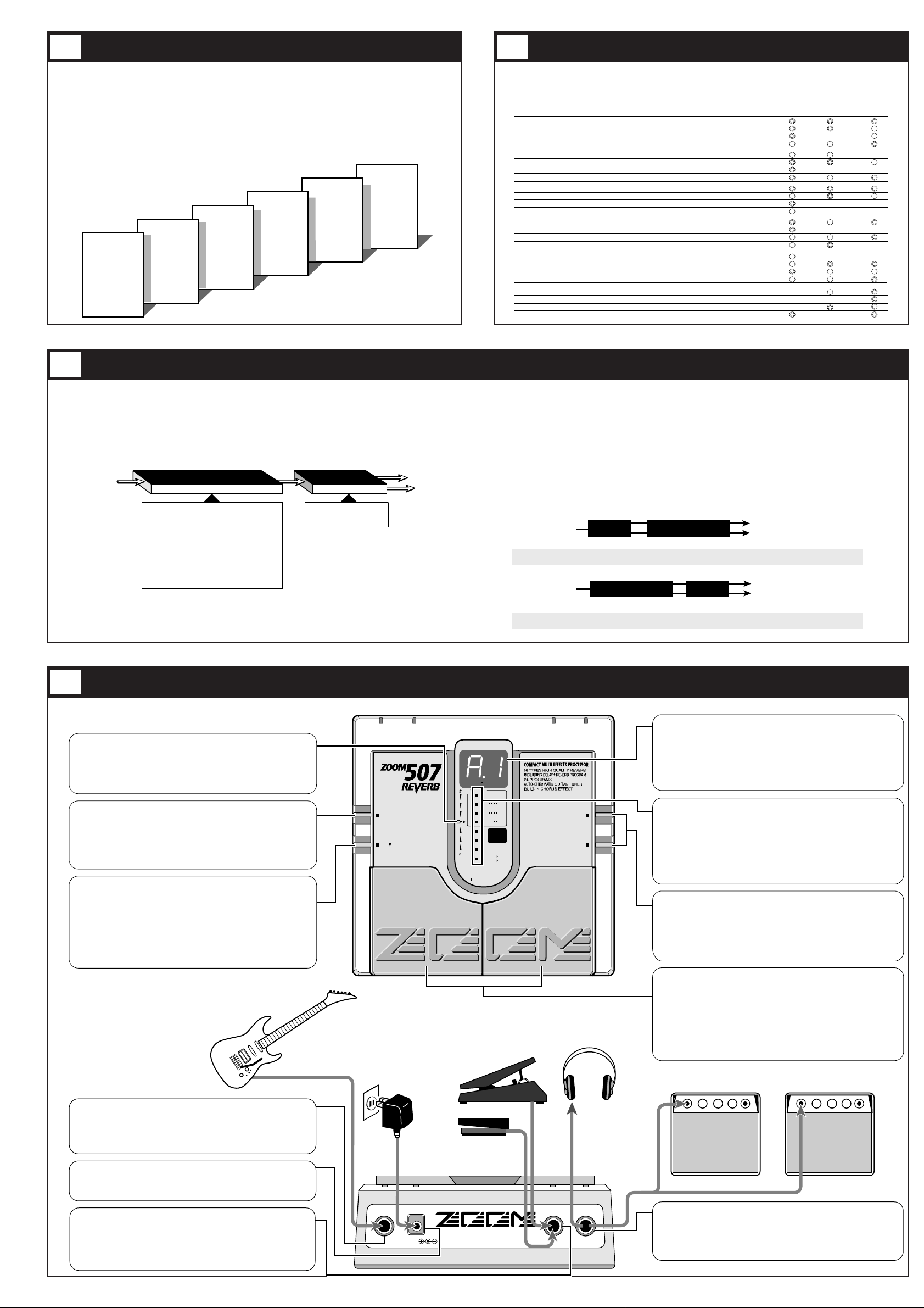
PATCH# PATCH CONCEPT EFFECT TYPE
for ELECTRIC
GUITAR
for ACOUSTIC
GUITAR
for MTR
& DTM
A1
A2
A3
A4
b1
b2
b3
b4
C1
C2
C3
C4
d1
d2
d3
d4
E1
E2
E3
E4
F1
F2
F3
F4
HALL 1
HALL 1
DLY+REV 1
ROOM 4
PLATE 3
ROOM 3
DLY+REV 1
DLY+REV 2
PLATE 2
DLY+REV 4
DLY+REV 3
HALL 2
HALL 4
DLY+REV 4
PLATE 1
HALL 3
ROOM 1
PLATE 4
ROOM 2
PLATE 2
PLATE 1
DLY+REV 2
ROOM 3
DLY+REV 1
with CHORUS
with CHORUS
with CHORUS
with FLANGE
with CHORUS
with FLANGE
with CHORUS
with CHORUS
with CHORUS
with CHORUS
with CHORUS
Basic hall reverberation
Reverberation for arpeggio with chorus
Delay + reverberation, suits playing melody
Basic room reverberation
Plate reverberation for guitar
Prominent short reverberation in ensemble
Chorus + delay + reverberation
SFX making everything sound like ethnic instruments
Basic plate reverberation
Catchy short delay, for cutting
Delay sound matching guitar sound
Reverberation + stereo flanger
Reverberation with crashing surf sound
High-quality doubling sound
Showy plate reverberation
Chorus + reverberation for acoustic guitar
Metallic echo like inside hollow pipe
Gate reverberation with chorus
Hard walled jazz club ambience
Plate for rock vocals
[ for Track down] Pops vocal echo
[ for Track down] Echo for traditional song
[ for Track down] Chorus part reverberation
[ for Track down] General guitar solo
When CHORUS module is connected before REVERB/DLY+REV module.
INPUT OUTPUT
L Channel
R Channel
CHORUS REVERB/DLY+REV
When CHORUS module is connected after REVERB/DLY+REV module.
INPUT OUTPUT
L Channel
R Channel
CHORUSREVERB/DLY+REV
C7 – C9: Flanger effect
 Loading...