

Installation Guide
DigiTract 4-2
Two Stage Heat/Cool
Comfort Control System
Part #DT4MAN
Rev. April 2003
Zoning Systems
That’s all we do.

TABLE OF CONTENTS...................................................................................................................................................................Page
INTRODUCTION.......................................................................................................................................................................................................1
SYSTEM DESCRIPTION...........................................................................................................................................................................................1
COMPONENT SELECTION GUIDE..........................................................................................................................................................................2
WIRING
Gas/Electric DTGE4-2.........................................................................................................................................................................................3
Heat Pump DTHP4-2..........................................................................................................................................................................................4
Zone Dampers....................................................................................................................................................................................................5
SYSTEM CONTROLLERS
Gas/Electric DTGE4-2
Operation...........................................................................................................................................................................................6
Status Lights .......................................................................................................................................................................................6
Components.......................................................................................................................................................................................7
Heat Pump DTHP4-2
Operation...........................................................................................................................................................................................8
Status Lights .......................................................................................................................................................................................9
Components.....................................................................................................................................................................................10
CAPACITY CONTROLLERS.....................................................................................................................................................................................11
Gas/Electric DTGE4-2.......................................................................................................................................................................11
Heat Pump DTHP4-2........................................................................................................................................................................11
Calibration .......................................................................................................................................................................................11
LAS Installation ................................................................................................................................................................................11
ZONE THERMOSTATS
Types ........................................................................................................................................................................................................12
Zonex Systems Gas/Electric Models..................................................................................................................................................................12
Digital (SADIGI)...............................................................................................................................................................................12
Digital (SADIGI) Operation..............................................................................................................................................................13
Programmable (101PROG)..............................................................................................................................................................12
Communicating (DIGICOM/DIGIHP)................................................................................................................................................12
Compatibility ....................................................................................................................................................................................................12
ZONE DAMPERS
Round ...................................................................................................................................................................................................14-15
Rectangular.................................................................................................................................................................................................16-17
Installation Notes..............................................................................................................................................................................................18
BYPASS DAMPERS
Barometric..................................................................................................................................................................................................18-19
Electronic ...................................................................................................................................................................................................20-21
Static Pressure Controller.................................................................................................................................................................22
DAMPER TRANSFORMER .....................................................................................................................................................................................23
SYSTEM STARTUP
Gas/Electric DTGE4-2.......................................................................................................................................................................................23
Heat Pump DTHP4-2........................................................................................................................................................................................24
Troubleshooting / Service Checks.....................................................................................................................................................................25
LAS Voltage – Temperature Conversion Chart..................................................................................................................................................25

Fused 24V Transformer
DIGITRACT 4-2
System Controller
73
73
73
73
5
2
3
1
4
6
ZONE 4
ZONE 3
ZONE 2
ZONE 1
LAS
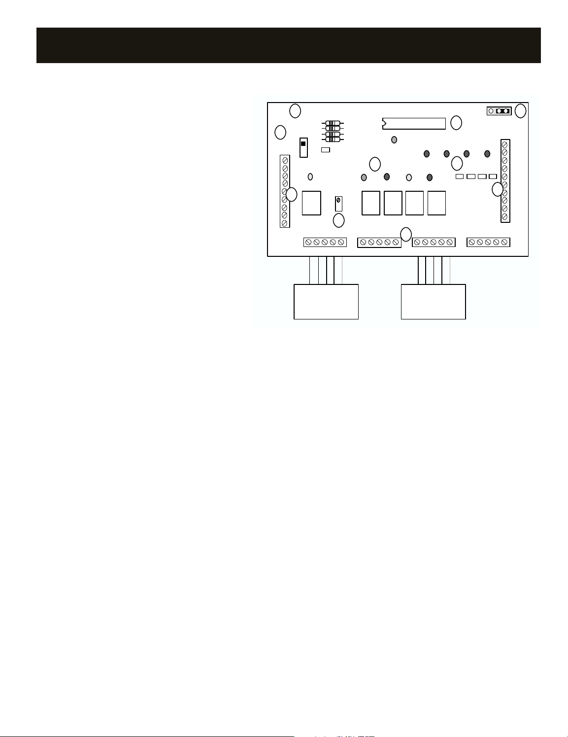
INTRODUCTION
System Controller
Leaving Air Sensor
Zone Damper
Zone Thermostat
Bypass Damper
Damper
Transformer
1
2
3
4
5
6
The Zonex Systems Digitract 4-2 zoning system enables up to four room thermostats to control a single HVAC system. This permits superior building
temperature control over a standard single thermostat. To provide economical, effective and simplified remote control and monitoring capability of
one or more Digitract 4-2 zone control systems, the ZonexCommander may be used to manage up to 80 thermostat schedules. The ZonexCommander is
a Windows®based thermal management system, which can integrate gas/electric and heat pump zone systems to include stand alone HVAC systems.
SYSTEM DESCRIPTION
The DigiTract 4-2 zoning system consists of a 2-stage System Controller
with built-in Capacity Control (leaving air sensor), Zone Dampers, Zone
Thermostats, Bypass Damper and Damper Transformer.
The System Controller is the heart of the Digitract 4-2 zoning system.
It monitors the leaving air temperature, zone thermostats and controls the
HVAC System and zone dampers. See pages 6 to 10 for further information.
The Leaving Air Sensor (LAS) is part of the staging and capacity control
feature of the System Controller. It is a sensor placed in the leaving air
of the HVAC system. The LAS monitors the leaving air temperature of the
HVAC system and sends this information to the System Controller. The
System Controller uses this information to stage and temporarily cycle
the HVAC system off if the leaving air gets too hot in heat mode or too cold
in cool mode. For heat pumps, this information is also used to control the
auxiliary heat to maintain a minimum supply air temperature of 88
degrees. See Capacity Controller section, page 11, for further information.
The Zone Dampers are air valves placed in the forced air duct work
for each zone. They are controlled by the System Controller. While the
HVAC system is running, the zone dampers for any zone thermostats not
calling will close and zone dampers for the zones calling will remain
open. Conditioned air is only directed to the zones needing it. See pages
14 to 18 for further information.
The Zone Thermostats monitor the room temperature of each zone
and compare it to the heat and cool setpoints stored in them. If the room
temperature drops below the heat setpoint, the zone thermostat makes
a heat call telling the System Controller that zone needs heating. If the
room temperature rises above the cool setpoint, that thermostat makes
a cool call telling the System Controller that zone needs cooling.
Two-stage thermostats are not required with the DigiTract 4-2 System.
The System Controller will cycle staging and auxiliary strip heat based on
leaving air temperature. See pages12 to 13 for further information.
The Bypass Damper is a pressure relief valve placed between the
supply and return ducts of the forced air duct work. As zone dampers
start closing, the bypass damper will open and divert some of the supply
air to the return. This prevents a pressure buildup in the supply duct
which can cause fan cavitation, excessive air velocities, and excessive
zone damper blow-by. See pages 18 to 22 for further information.
Damper Transformer. Wired to TR1 and TR2 on the System Controller.
Powers the zone dampers only. Requires an in-line fuse. See Damper
Transformer section, page 23.
1
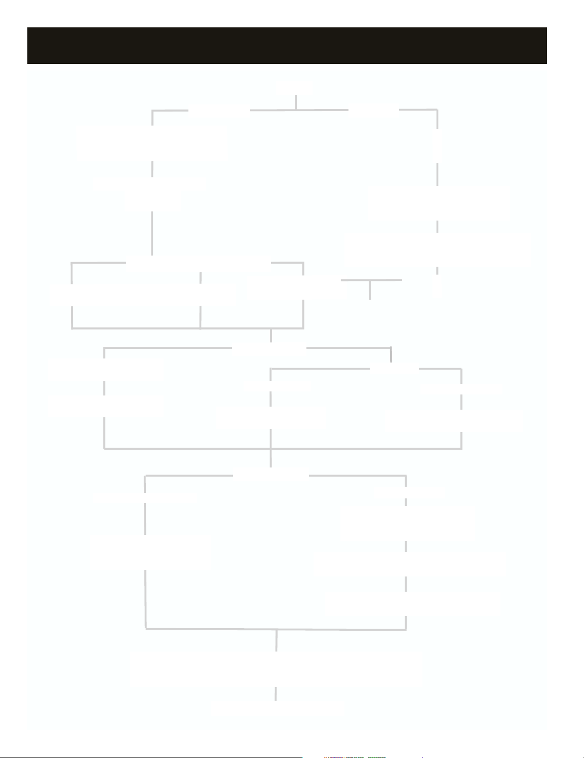
Digitract 4-2 COMPONENT SELECTION GUIDE
START
SYSTEM CONTROLLER
(DTGE4-2)
2-Stage Heat/Cool
CAPACITY CONTROLLER
System Controller includes Capacity Control
and Leaving Air Sensor
GAS/ELECTRIC THERMOSTATS
DIGITAL
(SADIGI)
5 TONS AND UNDER
(Up to 0.5” S.P.)
Round (TR diam)
Rectangular (TREC W x H)
GAS/ELECTRIC
PROGRAMMABLE
(101PROG)
COMMUNICATING
(DIGICOM)
ZONE DAMPERS
(Up to 1” S.P.)
Rectangular
(101MRTD W x H)
HEAT PUMP
SYSTEM CONTROLLER
(DTHP4-2)
3-Stage Heat/2-Stage Cool
CAPACITY CONTROLLER
System Controller includes Capacity Control
and Leaving Air Sensor
HEAT PUMP THERMOSTATS
(One per zone. Field Supplied.
See Thermostat Compatibility section, pg. 12)
COMMUNICATING
(DIGIHP)
COMMAND CENTER
(101CEC Communication Package,
one per 20 thermostats)
OVER 5 TONS
(Up to 1.75” S.P.)
Round (101AMPD diam)
Rectangular (101CD W x H)
5 TONS AND UNDER
BAROMETRIC BYPASS
Round (101ABBD diam)
Rectangular (RBB W x H)
BYPASS DAMPERS
OVER 5 TONS
ELECTRONIC BYPASS
Round (STMPD diam)
Rectangular (STCD W x H)
STATIC PRESSURE CONTROLLER
(101ASPC)
BYPASS TRANSFORMER
(FIELD SUPPLIED. 24VAC, 40VA)
DAMPER TRANSFORMER
(Field supplied. Requires in line fuse.
See Transformer/Fuse Sizing Table, pg. 23)
COMPLETE SYSTEM
2
Y1 G W1
PWR
DPR1 DPR2 DPR3 DPR4
ON
-
R
C
Y1
+
1
2
3
3
4
4
TR1
TR2
2
1
DIGITRACT 4-2 GE TWO STAGE 220108
AB
JPR1
Vx.x
R72
Y2
R8
R10
R9
R5
W
2
G
W1
Y2
Y2
W1
G
W2
Y1
R
C
ZONE 1
THERMOSTAT
ZONE 3
THERMOSTAT
-
+
STAT 1
W R Y G C
STAT 2
W R Y G C
STAT 3
W R Y G C
W R Y G C
STAT 4
W R Y G C
W R Y G C
W2
AIR FLOW
BYPASS
TAP
BYPASS
RETURN
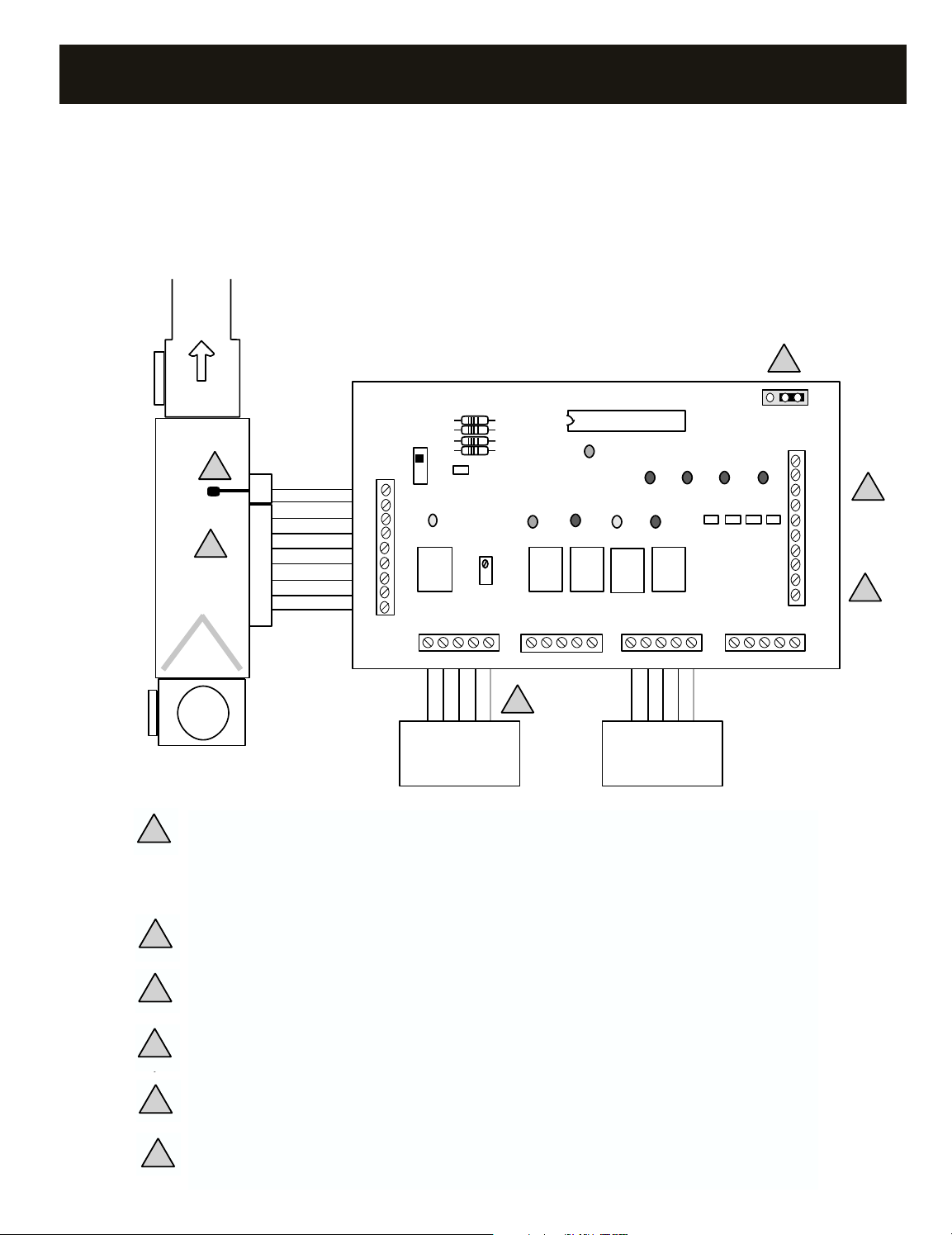
WIRING – GAS/ELECTRIC DTGE4-2
DigiTract 4-2 Gas/Electric 2-Stage Heat/Cool
HVAC unit and LAS terminals. Do not connect Y2 or W2 for single stage heat/cool systems.
Use minimum 18 gauge for all wiring.
All wiring must meet state and local codes.
Zone damper terminals. Refer to “Wiring – Zone Dampers” section, pg. 5.
1
2
6
4
1
2
3
4
3
1. LAS. Locate the leaving air sensor in the supply air stream, as far from the coil/heat exchanger as possible
before the bypass takeoff. Do not locate the LAS downstream of the bypass takeoff. Ensure wire polarity is
correct. Refer to "CAPACITY CONTROLLER- LAS INSTALLATION" on P. 11 for further information.
NOTE: Shielded conductor provided for installations with spark ignition or distances from controller to LAS
beyond 10’. 18/2 thermostat wire may be used in most applications.
2. Connect W2 and Y2 of the DTGE4-2 only if there are two heat and/or two cool stages.
3. Connect C from the controller to the thermostat 24V AC common terminal if hard wired. Not required
with use of battery operated thermostats. Refer to "THERMOSTATS- COMPATIBILITY" on P. 12 for further
information.
4. Zone damper terminals. Refer to "WIRING- ZONE DAMPERS" on P. 5.
5
5. Install one 24V AC transformer, sized and fused for the total number of zone dampers. See "DAMPER
5
TRANSFORMER" on P. 23.
6. Fan cycling jumper: A – FAU fan control; B – electric heat, fan on with heat call
6
3
Y1 G W2
PWR
DPR1 DPR2 DPR3 DPR4
ON
-
R
E
L
C
O/B
+
1
2
3
3
4
4
TR1
TR2
2
1
DIGITRACT 4-2 HP TWO STAGE 210806
BO
JPR1
Vx.x
R72
O/B
R
Y
G
C
STAT 4
O/B
R
YG
C
STAT 3
O/B
R
Y
G
C
STAT 2
STAT 1
O/B
RYGC
E
L
Y2
O/B
R8
R10
R9
R5
Y2
Y1
G
W2
W
G
Y1
Y2
O/B
R
E
C
+
-
AIR FLOW
O/B
RYG CW L
ZONE 1
THERMOSTAT
O/B R Y G C
ZONE 3
THERMOSTAT
1
2
3
4
7
5
6
BYPASS
TAP
BYPASS
RETURN
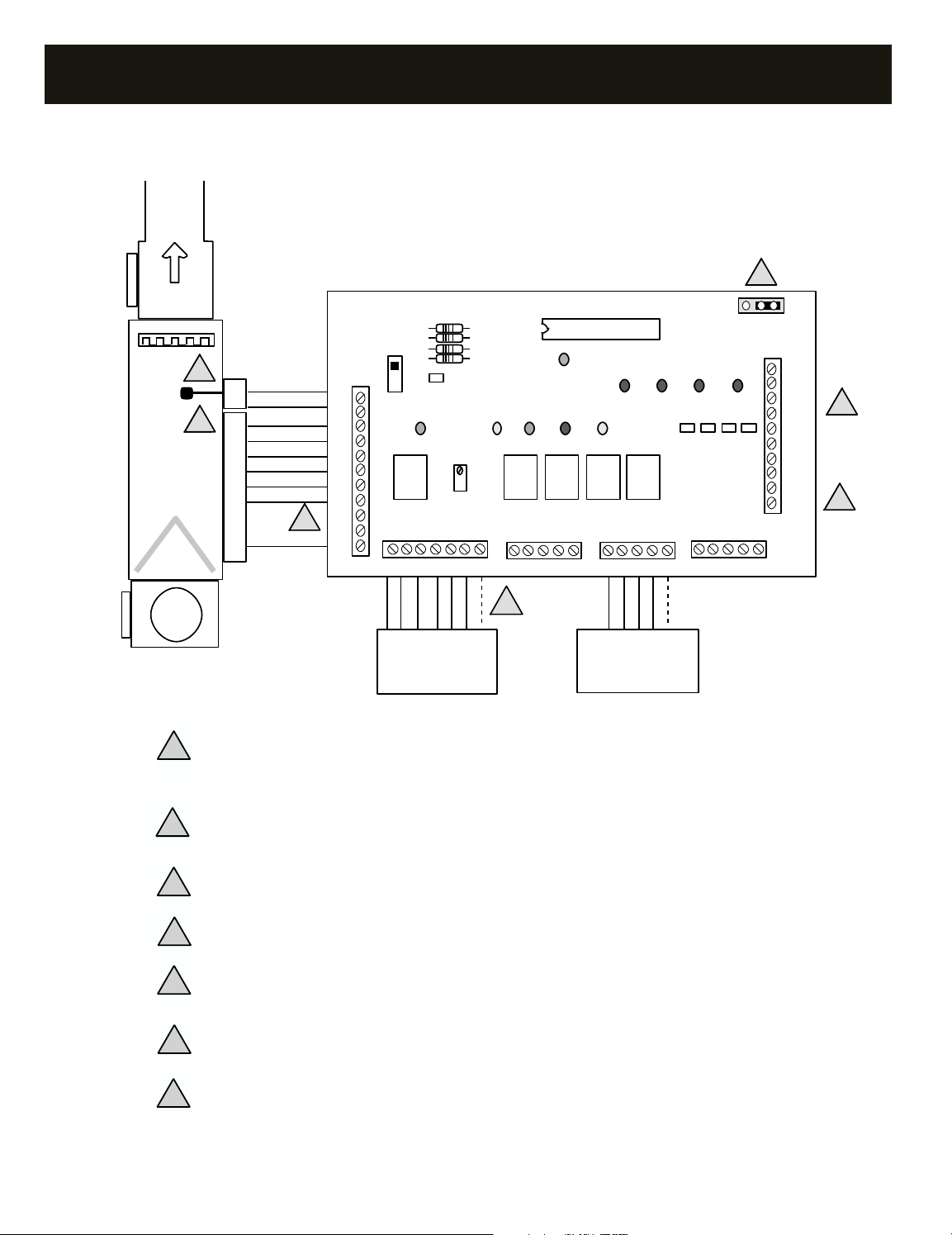
WIRING – HEAT PUMP DTHP4-2
DigiTract 4-2 HP 3-Stage Heat/2-Stage Cool
LAS. Locate the leaving air sensor between the refrigerant coil and the electric heat coil(s) or other auxiliary
1
heat source. Verify that the polarity is correct. Refer to “CAPACITY CONTROLLER – LAS INSTALLATION”
page 11, for further information.
Connect W2 from the controller to the unit’s electric heat stage terminal designation. It is recommended to
2
install an outdoor thermostat in series with any electric heat stages.
Connect C from the controller to the thermostat 24V AC common terminal if hardwired. Refer to “ZONE
3
THERMOSTATS – COMPATIBILITY” page 12, for further information.
Zone damper terminals. Refer to “WIRING – ZONE DAMPERS” on page 5.
4
Install one 24V AC transformer, sized and fused for the total number of zone dampers. See “DAMPER
5
TRANSFORMER” on page 23.
Emergency heat terminal, E. Use only if emergency heat source is different from auxiliary heat W2. If used,
6
do not jumper to W2.
Reversing valve jumper: B – energize for heat; O – energize for cool
7
NOTE: Some combination thermostats do not have an E terminal. Connect W2 of the thermostat to the E terminal of STAT 1 terminal block.
4

WIRING – ZONE DAMPERS
FUSED 24VAC XFMR.
Transformer and fuse must be sized for
total
number of
zone dampers. See Transformer/Fuse Sizing Table on
page 23.
TR
SERIES
DAMPER
M M
1
2
3
3
4
4
TR1
TR2
2
1
DIGITRACT 4-2
SYSTEM
CONTROLLER
TO TWO MORE TR SERIES
DAMPERS IF APPLICABLE
DMPR1DMPR
2
M M M M
DMPR
3
M M
DMPR
4
M M
1
2
3
3
4
4
TR1
TR2
2
1
TO ADDITIONAL
TR SERIES
DAMPERS IF
APPLICABLE
FUSED 24VAC XFMR.
Transformer and fuse must be sized for
total number
of zone dampers. See Transformer/Fuse Sizing
Table on page 23.
DIGITRACT 4-2
SYSTEM
CONTROLLER
24VAC
relay
1
2
3
3
4
4
TR1
TR2
2
1
DIGITRACT 4-2
SYSTEM
CONTROLLER
N/C - No connection
*
- Factory wired motor
101 series dampers include:
101AMPD, 101MRTD & 101CD
DAMPER RELAY BOARD
RC MCRCWWY RO
TB2
TB1
N/C N/CN/C
N/C N/C N/CN/CN/C
***
101 SERIES DAMPER
TO ADDITIONAL
101 SERIES DAMPERS
IF APPLICABLE
FUSED 24VAC XFMR.
Transformer and fuse must be sized for
total
number of zone dampers. See Transformer/Fuse
Sizing Table on page 23.
GRdBWWY
B must wire to bottom
terminal and Rd must wire
to top terminal. Do not
reverse.
{
{
G must wire to TR2.
Do not wire to TR1.
There are three methods of wiring the zone dampers. If necessary, you
can mix wiring methods on different zones to suit your application.
Method 1: If wiring two or three TR series dampers to a zone, wire per
Method 3: If using 101 series dampers with a DTGE4 controller, wire
per method 3. Notice: 101 series dampers are required for all systems
over 5 tons. Refer to Parts Selection Table, page 14.
method 1.
Method 2: If wiring more than three TR series dampers to a zone, use
method 2. This method requires a 24V ac, SPNO relay.
Method 1: Wiring Up to Three TR Series Dampers to a Zone
Method 2: Wiring More than Three TR Series Dampers to a Zone
Method 3: Wiring 101 Series Medium/Heavy Duty Dampers to a Zone
5
SYSTEM CONTROLLERS
The DigiTract 4-2 System Controller is the heart of the Digitract 4-2
zoning system. It is an auto changeover, home run system with a built in
staging and capacity controller. The function of the System Controller is
to receive calls from the zone thermostats, operate the HVAC system in
either heat or cool mode, and close the zone damper(s) of the zones not
calling for the operating mode. The mode of operation is determined by
the first call received. If thermostats are calling for opposite modes,
every 15 minutes it will change over to the other mode as long as there
SYSTEM CONTROLLER – GAS/ELECTRIC DTGE4-2
OPERATION
The System Controller will initially run in the mode requested by the first
calling zone thermostat.
Cool mode – When running in the cool mode, the System Controller
energizes the compressor(s) and indoor blower. This is indicated by the
corresponding Y and G LEDs illuminating. Dampers for the zones not
calling for cool are powered closed and the dampers for the zones
calling for cool are left open. This is indicated by the DPR LEDs. If the
DPR LED is illuminated on the damper terminal strip and damper
terminal board, the corresponding damper is closed. The system will
continue to run in the cool mode until all calls are satisfied or
changeover occurs. When all calls are satisfied or prior to changeover,
the system will go into a purge mode.
Heat mode – When running in the heat mode, the System Controller
energizes the heat stage(s), indicated by the W LEDs illuminating. If the
Fan Control Jumper is in the B position, the indoor blower will energize
with heat, indicated by the G LED illuminating. Dampers for the zones not
calling for heat are powered closed and the dampers for the zones calling
for heat are left open. This is indicated by the DPR LEDs. If the DPR LED
is on the damper terminal strip and damper terminal board, the corresponding damper is closed. The system will continue to run in the heat
mode until all calls are satisfied or changeover occurs. When all calls are
satisfied or prior to changeover, the system will go into a purge mode.
are opposing calls. The built in Capacity Controller maintains the supply
air temperature within an operating range to prevent freeze ups and
overheating. For heat pumps, the DTHP4 System Controller will also
control the auxiliary heat to maintain an 88 degrees minimum coil
leaving air temperature.
The DigiTract 4-2 is available in two models, Gas/Electric 2-Stage
Heat/Cool and Heat Pump 3-Stage Heat/2-Stage Cool.
Changeover – While the system is operating in one mode, and the
System Controller receives a call for the opposite mode, the System
Controller will continue to run in the current mode for 15 minutes or
until all current calls are satisfied. Then the System Controller will go
into a purge mode for 3 minutes, then change over to the new mode.
Purge mode – When all calls are satisfied or before changing
modes, the System Controller will go into a three minute purge cycle.
During this mode, the compressor or heat will turn off and the indoor
blower fan will continue to run. This is indicated by the W and Y LEDs
off and the G LED on. The damper(s) of the last calling zones will
remain open and all other damper(s) will be closed. This allows the
supply air to adjust to room temperature before changeover or ventilation while providing a time delay to prevent short cycling. The DPR
LEDs indicate which dampers are open and which are closed. If the
DPR LED is on, the damper is closed. If the DPR LED is off, the damper
is open.
Ventilation – When no zones are calling, all zone dampers are open.
During this time, if any thermostat has the fan switch ON then the indoor
blower is energized (G made to R) and the G LED is on. This provides
ventilation to all zones.
STATUS LEDS
Y1 Y2 G W1 W2 PWR DPR MODE FUNCTION
OFF OFF OFF OFF OFF OFF OFF Off Power off.
OFF OFF OFF OFF OFF ON OFF On Power on, blower off, all zones satisfied.
OFF OFF ON ON OFF ON 0 Vent Blower on, compressor(s) off, all zone dampers open.
OFF OFF ON OFF OFF ON 1 Purge Blower on, compressor(s) off. Dampers with LED on are closed.
ON OFF ON OFF OFF ON 1 Y1 cool 1st stage cool, blower on. Dampers with LED on are closed.
ON ON ON OFF OFF ON 1 Y2 cool 2nd stage cool, blower on. Dampers with LED on are closed.
OFF OFF A / B ON OFF ON 1 W1 heat 1st stage heat, blower on. Dampers with LED on are closed.
OFF ON A/ B ON ON ON 1 W2 heat 2nd stage heat, blower on. Dampers with LED on are closed.
OFF OFF ON OFF OFF FL 1 Cap cut out Blower on, all compressors off. Dampers with LED on are closed.
FL = Flashing A = On when JMPR1 is in Aposition B = OFF when JMPR1 is in B position
1 = One or more damper LED’s on 0 = All damper LED’s are off
6
SYSTEM CONTROLLER – GAS/ELECTRIC DTGE4-2
COMPONENTS
A. HVAC Unit/LAS Terminals – Connects to HVAC unit and
Leaving Air Sensor (LAS).
±: LAS terminals. The LAS monitors the leaving air
temperature.
W1: First stage heat. When energized (W1 made to R),
energizes first-stage heat.
W2: Second stage heat. When energized (W2 made to R),
energizes second-stage heat.
G: Blower. When energized (G made to R),
energizes the indoor blower.
Y1: First stage cool. When energized (Y1 made to R),
energizes first stage cooling.
Y2: Second stage cool. When energized (Y2 made to R),
energizes second stage cooling.
R: HVAC unit 24V power. Powers the DigiTract 4-2 board
and zone thermostats.
C: HVAC unit 24V power return.
B. Thermostat Terminals – Connects up to four zone
thermostats.
W: Heat call. When energized (W made to R),
requests the Digitract 4-2 to run in heat mode.
R: HVAC unit 24V power.
Y: Cool call. When energized (Y made to R),
requests the Digitract 4-2 to run in cool mode.
G: Blower Fan- When energized (G made to R), requests the
DigiTract 4 to turn on the indoor blower fan.
C: HVAC unit 24V power return.
C. Damper Terminals – Connects dampers for up to four zones and
damper power supply.
TR1/
TR2: 24V AC transformer terminals. This transformer powers only
the zone dampers.
1 1: Zone damper 1.
When energized, powers zone damper 1 closed.
2 2: Zone damper 2.
When energized, powers zone damper 2 closed.
3 3: Zone damper 3.
When energized, powers zone damper 3 closed.
4 4: Zone damper 4.
When energized, powers zone damper 4 closed.
D. Damper Status LEDs – On when corresponding zone damper is
being powered closed.
E. Board Number – This number indicates the circuit board number
and revision. May need to know this number if conferring with
technical support.
F. Heat Mode Fan Control Selection Jumper – In the A position,
the blower is energized by the furnace when heat is energized
(gas furnaces). In the B position, the blower is energized by the
DTGE4-2 when heat is energized (electric furnaces).
+
Y2
W1
G
W2
Y1
R
C
DIGITRACT 4-2 GE TWO STAGE 220108
E F
R8
R72
I
R10
R9
R5
W R Y G C
PWR
H
STAT 2
J
ON
-
Y1 G W1
A
STAT 1
W R Y G C
ZONE 1
THERMOSTAT
Vx.x
DPR1 DPR2 DPR3 DPR4
Y2
W2
STAT 3
B
W R Y G C
W R Y G CW R Y G C
ZONE 3
THERMOSTAT
JPR1
G
D
STAT 4
W R Y G C
G. Microcontroller – Responsible for activation and control of the
unit based upon thermostat input. Occasionally software upgrades
may become available. If so, the Digitract 4-2 software can be field
upgraded by changing this microcontroller.
H. HVAC System Status LEDs – Indicates what the DTGE4-2 is
energizing on the HVAC system.
Y1: Compressor, yellow. On when the first-stage cool is energized.
Y2: Compressor, yellow. On when the second-stage cool is energized.
G: Blower, green. On when the indoor blower is energized.
W1: Heat, red. On when first stage heat is energized.
W2: Heat, red. On when second stage heat is energized.
PWR: Power, orange. On when power at R and C and the Power
Switch is on. Flashing when in Capacity Control cut out mode.
See Status Lights section, page 6, for further information.
I. Leaving Air Sensor Potentiometer – Turn to calibrate the
leaving air sensor if required. See Calibration in Capacity Controller
section.
J. Power Switch – When OFF, power from the HVAC unit transformer is
disconnected from the Digitract 4-2 and thermostats. When ON, power
from the HVAC unit transformer is supplied to the Digitract 4-2 and
the zone thermostats.
AB
C
TR1
TR2
1
1
2
2
3
3
4
4
7

SYSTEM CONTROLLER – HEAT PUMP DTHP4-2
OPERATION
The System Controller will initially run in the mode requested by the first
calling zone thermostat.
Cool mode – When running in the cool mode, the System Controller
energizes the compressor(s), indoor blower and energizes the
reversing valve (O/B made to R) if the reversing valve selection jumper
is in the O position. This is indicated by the corresponding Y, G and O/B
(if jumper in O position) LEDs illuminating. Also, the dampers for the
zones not calling for cool are closed and the dampers for the zones
calling for cool are left open. This is indicated by the DPR LEDs. If the
DPR LED is illuminated, the damper terminal strip and damper
terminal board, the corresponding damper is closed. The system will
continue to run in the cool mode until all calls are satisfied or
changeover occurs. When all calls are satisfied or prior to
changeover, the system will go into a purge mode.
Heat mode – When running in the heat mode, the System Controller
energizes the compressor(s), indoor blower and energizes the
reversing valve if the reversing valve selection jumper is in the B
position. This is indicated by the corresponding Y, G and O/B (if
jumper in B position) LEDs illuminating. Also, the dampers for the
zones not calling for heat are closed and the dampers for the zones
calling for heat are left open. This is indicated by the DPR LEDs. If the
DPR LED is on the damper terminal strip and damper terminal board,
the corresponding damper is closed. After running in heat mode for 8
minutes, the System Controller will energize the auxiliary heat if the coil
leaving air temperature drops below 88 degrees and will deenergize
when the coil leaving air temperature rises above 97 degrees. The W2
LED is on when the auxiliary heat is energized. The system will continue
to run in the heat mode until all calls are satisfied or changeover
occurs. When all calls are satisfied or prior to changeover, the system
will go into a purge mode.
Purge mode – When all calls are satisfied or before changing modes,
the System Controller will go into a 3-minute purge cycle. During this
mode the compressor and indoor blower will deenergize. This is
indicated by the Y and G LEDs cycling off. If the reversing valve is
energized, it will deenergize. This is indicated by the O/B LED turning
off. The damper of the last calling zone will remain open and all other
dampers will be closed. This provides a 3-minute time delay to prevent
equipment short cycling. The DPR LEDs indicate which dampers are
open and which are closed. If the DPR LED is on, the damper is closed.
If the DPR LED is off, the damper is open.
Auxiliary heat – 8 minutes after the System Controller has run in heat
mode, if the coil leaving air temperature is below 88 degrees, the
auxiliary heat is energized and the W2 LED illuminates. When the coil
leaving air temperature rises above 97 degrees, the auxiliary heat is
deenergized and the W2 LED cycles off.
Ventilation – When no zones are calling, all zone dampers are open.
During this time, if any thermostat has the fan switch ON then the
indoor blower is energized and the G LED is on. This provides
ventilation to all zones.
Emergency heat – Emergency heat mode is controlled by STAT1 only.
To make an emergency heat call, STAT1 must be in Emergency Heat
mode and making a heat call. When the System Controller receives an
emergency heat call from STAT 1, it will lock-out the compressors and
energize the auxiliary heat strips and fan unless the system is already
running in heat or cool mode. If the system is running, the unit’s
auxiliary heat will be energized based on leaving air temperature. Zones
not calling for heat will close their dampers. When all zone temperatures
are satisfied, the System Controller removes the auxiliary heat call and
monitors all zones for the next call.
Changeover – While the system is operating in one mode, if the
System Controller receives a call for the opposite mode, the System
Controller will continue to run in the current mode for 15 minutes or
until all current calls are satisfied. Then the System Controller will go
into a purge mode for 3 minutes, then change over to the new mode.
8

SYSTEM CONTROLLER – HEAT PUMP DTHP4-2
STATUS LEDs
O/B Reversing valve LED, yellow. On when the reversing valve is energized.
Y1 Compressor LED, yellow. On when the first compressor stage is energized.
Y2 Compressor LED, yellow. On when the second compressor stage is energized.
G Indoor blower LED, green. On when the indoor blower is energized by the DTHP4-2 Controller.
W2 Auxiliary heat LED, red. On when the auxiliary heat is energized.
PWR Power LED, orange. On when DTHP4-2 is powered. Flashing during capacity control cutout.
DPR Damper status LED, red. One per damper. On when damper is closed.
STATUS LEDs
O/B Y1 Y2 G W2 PWR DPR MODE FUNCTION
OFF OFF OFF OFF OFF OFF OFF Off Power off.
OFF OFF OFF OFF OFF ON OFF On Power on, blower off, all zones satisfied.
OFF OFF OFF ON OFF ON 0 Vent Blower on, compressor(s) off, all zone dampers open.
OFF OFF OFF ON OFF ON 1 Purge Blower off, compressor(s) off. Dampers with LED on are closed.
A ON OFF ON OFF ON 1 Y1 Cool 1st stage cool, blower on. Dampers with LED on are closed.
A ON ON ON OFF ON 1 Y2 Cool 2nd stage cool, blower on. Dampers with LED on are closed.
B ON ON ON C ON 1 Y1 Heat 1st stage heat, blower on. Dampers with LED on are closed.
B ON ON ON C ON 1 Y2 Heat 2nd stage heat, blower on. Dampers with LED on are closed.
OFF OFF OFF ON ON ON 0 Em. Heat Auxiliary and emergency heat on.
OFF OFF OFF ON OFF FL 1 Cap Cut out Blower on, all compressors off. Dampers with LED on are closed.
FL = Flashing A = On when reversing valve jumper is in O position B = On when reversing valve jumper is in B position
C = On when auxiliary heat is energized 1 = One or more damper LEDs on 0 = All damper LEDs are off
COMPONENTS DTHP4-2
+
-
W2
G
Y1
Y2
O/B
R
E
L
C
DIGITRACT 4-2 HP TWO STAGE 210806
R8
R72
J
R10
R9
R5
PWR
I
Y1 G W2
STAT 2
O/B R Y G C
H
ON
A
STAT 1
O/BR Y G CEL
Vx.x
DPR1 DPR2 DPR3 DPR4
Y2O/B
STAT 3
B
O/B R Y G C
JPR1
G
D
STAT 4
O/B R Y G C
BO
C
EF
1
1
2
2
3
3
4
4
TR1
TR2
9

SYSTEM CONTROLLER – HEAT PUMP DTHP4-2
COMPONENTS (Continued)
A. Heat Pump Unit/LAS Terminals – Connects to Heat Pump and
Leaving Air Sensor (LAS).
±: LAS terminals. The LAS monitors the heat pump coil leaving air
temperature.
W2: Auxiliary Heat. When energized (W2 made to R), turns on the
heat pump auxiliary heat.
G: Blower. When energized (G made to R), turns on the
indoor blower.
Y1: Compressor. When energized (Y1 made to R), turns on the heat
pump first stage compressor.
Y2: Compressor. When energized, (Y2 made to R), turns on the
heat pump second stage compressor.
O/B: Reversing Valve. When energized (O/B made to R), engages
the heat pump reversing valve.
R: Heat pump unit 24V power. Powers Digitract 4-2 and
thermostats.
E: Emergency Heat. Separate output (E made to R) to cycle additional
stages (if applicable) when in the emergency heat mode.
L: Compressor Fail Flag. Connected to L of STAT1 terminal. See B.
C: Heat pump unit 24V power return.
B. Thermostat Terminals – Connects up to four zone heat pump
thermostats.
L: Compressor Fail Flag. On STAT1 only. Connected to L of Heat
Pump Unit terminal (see A). If the heat pump compressor fails,
the heat pump will energize L (R made to L) which will turn on
an indicator light on thermostat 1. This feature is not available
on all heat pumps and/or thermostats.
E: Auxiliary/Emergency Heat. On STAT 1 only. Connected to E
terminal on STAT 1. When thermostat 1 is in the emergency
heat mode and making a heat call, Y is locked out and W is
energized as the first stage of heat. The W2 and E outputs from
the controller will be energized simultaneously.
NOTE: When the controller receives a STAT 1 E input from the
thermostat W terminal when in the normal heat mode, it is
ignored. The W2 output of the controller is cycled according to
leaving air temperature.
0/B: Mode control. For O thermostats, thermostat is in cool mode
when energized (O/B made to R) and in heat mode when not
energized. The reverse is true for B thermostats.
R: Heat pump unit 24V power. See A.
Y: Compressor. When energized (Y made to R), requests that the
DGHP4-2 energize the heat pump compressor.
G: Blower. When energized (G made to R), requests that the
DTHP4-2 energize the indoor blower fan.
C: Heat pump unit 24V power return.
C. Damper Terminals – Connects dampers for up to four zones and
damper power supply.
TR1/
TR2: 24V AC transformer terminals. This transformer powers only
the zone dampers.
1 1: Zone damper 1. When energized, powers zone damper 1 closed.
2 2: Zone damper 2. When energized, powers zone damper 2 closed.
3 3: Zone damper 3. When energized, powers zone damper 3 closed.
4 4: Zone damper 4. When energized, powers zone damper 4 closed.
D. Damper Status Lights – Light on when corresponding zone
damper is closed.
E. Reversing Valve Selection Jumper – Configures Digitract 4-2 to
energize reversing valve in cool mode or heat mode. Place on O and
center pin to energize reversing valve in cool mode. Place on B and
center pin to energize in heat mode.
F. Board Number – This number indicates the circuit board number
and revision. May need to know this number if conferring with
technical support.
G. Microcontroller – Responsible for activation and control of the
unit and dampers based upon thermostat input. Occasionally
software upgrades may become available. If so, the Digitract 4-2
software can be field upgraded by changing this microcontroller.
H. Power Switch – When OFF, power from the heat pump transformer
is disconnected from the Digitract 4-2 and thermostats. When ON, power
from the heat pump transformer is supplied to the Digitract 4-2 and
the zone thermostats.
I. Heat Pump Status LEDs – Indicates what the DTHP4-2 is
energizing on the heat pump.
O/B: Reversing valve, yellow. On when the reversing valve is
energized.
Y1: Compressor, yellow. On when the first stage compressor is
energized.
Y2: Compressor, yellow. On when the second stage compressor is
energized.
G: Blower, green. On when the indoor blower is energized.
W2: Auxiliary heat, red. On when the auxiliary heat is energized.
PWR: Power, orange. On when power at R and C and the Power
Switch is on. Flashing when in Capacity Control cut out mode.
See Status Lights section, page 9, for further information.
J. Leaving Air Sensor Potentiometer – Turn to calibrate the leaving
air sensor, if required. See Calibration, in Capacity Controller section.
10

STAGING AND CAPACITY CONTROL
+
-
Y2
W1
G
W2
R
Y1
C
The HVAC system is sized to handle the load of the entire home
or building. Because of this, when all the zones are not calling, the load
to the HVAC system can diminish below its designed capacity. Left
unchecked, the HVAC unit could freeze up or overheat. To compensate
for this, the Digitract 4-2 is furnished with a built in Capacity Controller.
The basic function of the Capacity Controller is to monitor the leaving air
temperature and cycle the unit off when the air is out of operating range
and, after a minimum four minute time delay, turn the unit back on when
the air temperature has returned within operating range. Additionally, for
heat pumps the Capacity Controller will turn on the heat pump auxiliary
heat if the coil leaving air temperature is not hot enough in heat mode.
COOLING OPERATION – DTGE4-2 AND DTHP4-2
Y1 Cool Operation – Upon a cool call, the controller will energize Y1
and operate with a minimum run time of 4 minutes, regardless of the
leaving air temperature. At the completion of the minimum run time, if
the leaving air temperature drops below 45°F., Y is deenergized; the Y
LED is off and the PWR LED will flash. G will remain energized, upon
which the leaving air temperature is rechecked after 4 minutes. If
the leaving air temperature has recovered to 45°F. or greater, Y will be
reenergized and the PWR LED will stop flashing. If the reversing
valve jumper is in the O position, the O/B output will be energized
simultaneously with Y, indicated by the O/B LED.
Y2 Cool Operation – After 8 minutes of continuous Y1 run time, the
leaving air temperature, LAT is checked. If the LAT is above 60°F., Y2 will
be energized and the Y2 LED will illuminate. Y2 will cycle off when the
LAT drops below 50°F., or when all cool calls are satisfied.
HEAT OPERATION – GAS/ELECTRIC DTGE4-2
W1 Heat Operation – Upon a heat call, the controller will energize W1
if the leaving air temperature is less than 145°F. W1 will deenergize if
the LAT exceeds 145°F. The W1 LED will then cycle off and the PWR LED
will begin to flash indicating a capacity control cutout. After a 4-minute
recycle timer has completed, W1 will energize if the LAT is below 145°F.
W2 Heat Operations – After W1 has operated continuously for 4
minutes and the LAT is 120°F or less, W2 will energize. W2 will remain
energized until the LAT rises above 135°F or if all heat calls become
satisfied. The W2 LED will then cycle off.
HEAT OPERATION – HEAT PUMP DTHP4-2
Y1 Heat Operation – Upon a heat call, the controller will energize Y1
and operate with a minimum run time of 4 minutes, regardless of the leaving
air temperature. At the completion of the minimum run time, if the
leaving air temperature rises above 120°F, Y1 is deenergized; the Y LED is
off and the PWR LED will flash. G will remain energized, upon which the
leaving air temperature is rechecked after 4 minutes. If the leaving air
temperature has recovered to 120°F. or lower Y1 will recycle and the
PWR LED will stop flashing. If the reversing valve jumper is in the
O position, the O/B output will be energized simultaneously with Y,
indicated by the O/B LED.
Y2 Heat Operation – After 4 minutes of continuous Y1 run time, the
leaving air temperature, LAT is checked. If the LAT is below 95°F., Y2 will
be energized and the Y2 LED will illuminate. Y2 will cycle off when the
LAT rises above 105°F., or when all heat calls are satisfied.
Auxiliary Heat – After 8 minutes of continuous Y1 operation the leaving
air temperature, LAT is checked. If the LAT is below 88°F., W2 will be
energized and the W2 LED will illuminate. W2 will cycle off when the LAT
rises above 97°F., or when all heat calls are satisfied.
CAPACITY CONTROLLER – CALIBRATION
The Capacity Controller comes factory calibrated. However, if field calibration is ever necessary, perform the following:
1. Use a digital, DC voltmeter with 3 digits to the right of the decimal accuracy.
2. On the System Controller, place - probe of voltmeter to C terminal and + probe to left side of second resistor from top (R10) as shown in adjacent diagram.
3. Measured voltage should read 2.718 VDC. If the voltage is incorrect, slowly adjust potentiometer R72 until 2.718 VDC is obtained.
DC
Voltmeter
2.718
+
–
4. The LAS is now calibrated.
CAPACITY CONTROLLER – LAS INSTALLATION
A. Cut or drill a hole in selected location large enough to fit sensor through.
B. Select location to install the LAS. For gas/electric HVAC systems, sensor must be in leaving air duct, preferably as
far from the coil/heat exchanger as possible but not past the bypass tap. For heat pumps, locate LAS downstream
from indoor coil but before auxiliary heat strips.
C. Place sensor through hole made in duct and mount Capacity Controller to duct with screws. Use grommet or tape
to protect sensor wire from sharp edges.
D. The cable between the LAS sensor and the controller must be installed separately from all 24 volt control and
power wiring. Using the shielded cable provided, connect the LAS between the + and – terminals of the controller
as shown. The shielded conductor is provided for installations with spark ignition or distances from controller to
LAS beyond 10’. 18/2 thermostat wire may be used in most applications.
Terminate the shield at the controller end only on the “C” terminal of the equipment terminal block.
Important: The shield at the LAS end of the wire must not be grounded, or attached to any other terminal.
The shield should be cut and taped off at the LAS end to prevent grounding.
11
R72
C
SHIELD

ZONE THERMOSTATS
Each zone requires a zone thermostat. The following lists the types of
thermostats to use with each Digitract 4-2 system, information on Zonex
Systems thermostats and how to select a thermostat not manufactured by
Zonex Systems.
ZONE THERMOSTATS – TYPES
Gas/Electric DTGE4-2 – Use 24V ac single stage gas/electric thermostats.
Zonex Systems offers three models: SADIGI, 101PROG and DIGICOM.
If not using Zonex Systems thermostats, see Thermostat Compatibility
section below.
Heat pump DTHP4-2 – Use 24V ac single stage heat, single stage cool
heat pump thermostats. If emergency heat feature is preferred then the
thermostat for Stat1 must have the emergency heat mode feature. If the
heat pump has the compressor fail flag feature, STAT1 should also have
a compressor fail light. See Thermostat Compatibility section below.
ZONEX SYSTEMS THERMOSTATS
Zonex Systems offers three thermostat models that can be used with the Gas/Electric Digitract 4-2 System
Controller (DTGE4). These models are SADIGI, 101PROG and DIGICOM.
SADIGI: The SADIGI is a single stage gas/electric, hard wired (non-power robbing) thermostat. It can
control one heat, one cool and blower fan. It can run in Heat, Cool, or Auto changeover mode. Setpoint
range is from 55° to 86° Fahrenheit. The mode and setpoints are stored in nonvolatile memory so they
will be remembered even if power is interrupted. It has a bright and easy to read digital display and is
simple to operate. Up and down push buttons select the mode and setpoint(s). Under the cover of the
thermostat there are two mode status lights: one red and one green. The red light is on when the
thermostat is making a heat call. The green light is on when the thermostat is making a cool call. The
dimensions are: 2
and G. Requires 5 conductor thermostat wire. Can be ordered with remote sensor; p/n SADIGIRS.
7
⁄8”W x 41⁄2”H x 1”D, the color is off white. Terminal designations are: R, C, Y, W
101PROG: Programmable, dual setpoint, single stage heat/cool, electronic, non power robbing, auto
changeover, weekday/weekend (5,1,1) programmable, manual override capable. Thermostat includes
a large LCD that displays time, day, program, setpoints and room temperature. Can program up to four
different schedules per day. Battery backup memory. Dimensions are: 6”W x 3
five thermostat wires for installation. Color: White. Can be ordered with remote sensor; p/n 101PROGRS.
DIGICOM/DIGIHP: The DIGICOM and DIGIHP are auto changeover, communicating thermostats used
exclusively in ZonexCommander thermal management systems. Using a computer and the ZonexCommander
software, all thermostats in the system can be programmed and viewed. The DIGICOM/DIGIHP may
be applied in stand alone unit control, from 1 to 20 split or packaged systems. When used with a
modem, all ZonexCommander software functions can be controlled remotely. The DIGICOM/DIGIHP
requires 24V AC power from either the zone system or HVAC unit transformer, with the addition of a two
conductor, twisted pair cable for communications. Dimensions: 2-7/8” W x 4-1/2” H x 1” D.
1
⁄2”H x 13⁄4”D. Requires
ZONE THERMOSTATS – COMPATIBILITY
The DTGE4-2 gas/electric and DTHP4-2 heat pump controllers are compatible with most thermostats,
offering a wide thermostat selection to the installing contractor. When using other than Zonex Systems
thermostats, please refer to the following guidelines:
Electronic Thermostats: Digital thermostats requiring 24V AC power must be “Hard wired” with a
separate R and C or common terminal. Power robbing type thermostats are not compatible. All types
of battery operated thermostats may be used with any Digitract 4-2 control system.
Mechanical Thermostats: When using a mechanical thermostat, ensure the cooling compensator
(anticipator) is removed, and the heating anticipator is shorted or set to its lowest setting.
SADIGI
Please contact Factory Technical Support for additional thermostat compatibility information.
12
DIGICOM/DIGIHP

SADIGI THERMOSTAT OPERATING INSTRUCTIONS
Lower heat
setpoint
Pwr
Off/On
Fan
On/Auto
A
C
H
Raise heat
setpoint
Lower cool
setpoint
Raise cool
setpoint
H
72
70
C
74
76
View heat
setpoint
View cool
setpoint
73
SLIDE SWITCHES
There are two switches located on the bottom of the thermostat. The switch on the left controls
the fan and the switch on the right powers the thermostat. Sliding the fan switch to the left
turns the indoor blower fan on continuously. Sliding it to the right runs the fan only when the air
conditioner is on. Slide the power switch to the right to turn on the thermostat and to the left to
turn it off.
MODE
The SADIGI thermostat can operate in three different modes: Heat, Cool or Auto. In Heat mode,
the SADIGI can only make heat calls and only the heat setpoint can be viewed or changed. In Cool
mode, the SADIGI can only make cool calls and only the cool setpoint can be viewed or changed.
In Auto mode, the SADIGI can make either heat or cool calls and both the heat and cool setpoints
can be viewed.
View mode: To view the current mode, press the top and bottom buttons simultaneously.
The present mode will be displayed by the letter H, C or A.
Change mode: To change the mode, continue simultaneously pressing both the top and bottom
buttons until at the mode desired, then release both buttons.
When the SADIGI thermostat is in Auto or Heat mode, the thermostat will make a heat call when
the room temperature drops two degrees below the heat setpoint and, after running a minimum
of 2 minutes, turn off when the temperature has risen to the heat setpoint. When in Auto or Cool
mode, the thermostat will make a cool call when the room temperature rises two degrees above
the cool setpoint and, after running a minimum of 2 minutes, turn off when the temperature has
dropped to the cool setpoint.
View/change heat setpoint: The heat setpoint can be viewed when in either Auto or Heat mode.
To view the current heat setpoint in Auto mode, press the top button until “H” appears and then
release. To view in Heat mode, press either the top or bottom button until “H” appears and then
release. The heat setpoint is displayed after “H”. To change the setpoint, immediately after
the setpoint is displayed press and hold either the top or bottom button until the setpoint is at
the desired value and then release. Approximately two seconds after the button is released the
current room temperature will be redisplayed.
SETPOINTS
View/change cool setpoint: The cool setpoint can be viewed when in either Auto or Cool mode.
To view the current cool setpoint in Auto mode, press the bottom button until “C” appears and
then release. To view in Cool mode, press either the top or bottom button until “C” appears and
then release. The cool setpoint is displayed after “C”. To change the setpoint, immediately
after the setpoint is displayed press and hold either the top or bottom button until the setpoint is at
the desired value and then release. Approximately two seconds after the button is released the
current room temperature will be redisplayed.
13

SYSTEM SIZE
5 TONS OR UNDER
UNDER 7.5 TONS
7.5 TONS OF LARGER
MAXIMUM
DIFFERENTIAL
PRESSURE
0.5"
1"
1.75"
ROUND
DAMPER
LOW PRESSURE
MEDIUM PRESSURE
MEDIUM PRESSURE
RECTANGULAR
DAMPER
LOW PRESSURE
MEDIUM PRESSURE
HEAVY DUTY
ZONE DAMPERS
Zonex Systems zone dampers are used in cooling/heating systems to
provide room by room zone control. The damper is provided with a
factory mounted relay board and zone actuator. Each zone damper is
Maximum Differential Pressure refers to the maximum static pressure drop in inches of water column between the
input (upstream) of the zone damper and the output (downstream) when the damper is closed.
controlled by a zone thermostat. More than one damper can be controlled
by one zone thermostat; see Slaving Dampers. Use the table below to
determine which zone dampers to use.
ROUND ZONE DAMPERS
There are two styles of round zone dampers, low pressure or medium
pressure. For systems 5 tons or under with a maximum differential static
pressure of 0.5”, use low pressure dampers. Otherwise use medium
pressure for up to 1.75” differential pressure on any system over 5 tons.
ROUND LOW PRESSURE ZONE DAMPERS (TR diam)
Zonex Systems round low pressure zone dampers can be used for systems up to 5 tons
with a maximum differential static pressure of 0.5”. These are two position, spring
open, power close dampers for very simple operation. Round damper sizes 9
inches and under are manufactured from 24 gauge galvanized steel. Sizes 10”, 12”,
14” and 16” are made from 20 - 22 gauge steel. All sizes are designed with rolled-in
stiffening beads for superior rigidity. The damper pipe is furnished with one crimped end
and one straight end for easy installation. A hat section supports a synchronous 24V
AC 60Hz 12VA motor and terminal board. The motor is designed for continuous full stall
operation. Special winding and heavy duty gearing provide for long motor life and
easy spring open operation. A cross pin on the motor shaft provides positive direct drive
to the damper blade shaft without a coupling or set screws, allowing for a quick and easy
motor change if required. Motor drive time from full open to full close is 30 seconds.
A red LED will be illuminated on the damper terminal board to indicate when the
damper is being powered closed. The LED will remain on when the damper is fully closed
and cycle off when the damper is opening or in the full opened position. Since this is a
spring open damper, in the event of power failure, the damper fails to the full open position.
LOW PRESSURE (TR diam)
ROUND MEDIUM PRESSURE ZONE DAMPERS
(101AMPD diam)
Zonex Systems round medium pressure zone dampers are recommended for systems over
5 tons or with a maximum differential static pressure up to 1.75”. This power open /
power close damper is manufactured from 20-22 gauge galvanized steel with rolled-in
stiffening beads for superior rigidity. Mechanical minimum and maximum set stops are
provided and easily adjustable. The damper pipe is furnished with one crimped end and
one straight end for easy installation. A hat section supports a 35 lb./in. 24V, 6 VA power
open, power closed actuator with a damper relay board interface. The actuator is
designed for full stall operation, with a magnetic clutch to protect the internal gearing.
The actuator is direct coupled to the damper shaft, which provides positive operation and
offers replacement ease if required. Drive time from full open to full closed is 60 seconds.
14
MEDIUM PRESSURE (101AMPD diam)

ROUND LOW & MEDIUM PRESSURE DAMPER SIZES
ROUND LOW PRESSURE DAMPER
PART #
TR06
TR07
TR08
TR09
TR10
TR12
TR14
TR16
ROUND MEDIUM PRESSURE DAMPER
PART #
101AMPD06
101AMPD08
101AMPD10
101AMPD12
101AMPD14
101AMPD16
101AMPD18
SIZE DIAMETER (D) LENGTH (L)
6"
7"
8"
9"
10"
12"
14"
16"
SIZE DIAMETER (D) LENGTH (L)
6"
8"
10"
12"
14"
16"
18"
6"
7"
8"
9"
10"
12"
14"
16"
6"
8"
10"
12"
14"
16"
18"
ZONE DAMPERS
WIDTH (W)
10"
10"
10"
11"
12"
14"
16"
18"
10"
10"
12"
14"
16"
18"
20"
9"
10"
11"
12"
13"
15"
17"
18 1/2"
WIDTH (W)
9"
11"
13"
15"
17"
19"
21"
W
D
L
TYPICAL ROUND CAPACITIES*
Duct
Diameter
6"
7"
8"
9"
10"
12"
14"
16"
18" 2000 1100 .036
Nominal
CFM
110
160
250
320
410
660
1000
1450
Duct Velocity
FPM
540
600
700
725
750
850
925
1070
Damper
P " WC
∆
.014
.014
.015
.015
.015
.022
.035
.036
* These air quantities were derived from a duct sizing chart .1” friction loss per 100’ of duct. All CFMs listed are approximate. For accurate selection
use duct sizing table or device.
15

ZONE DAMPERS
RECTANGULAR ZONE DAMPERS
The rectangular zone dampers are available in low, medium and heavy duty pressure ratings. For systems up to 5 tons or with .5” ESP blower
capacity, use low pressure rated dampers. For systems up to 7.5 tons or with a 1.0” ESP blower capacity, use medium pressure rated
dampers. For systems over 7.5 tons or up to 1.75” ESP blower capacity, use heavy duty rated dampers.
RECTANGULAR LOW PRESSURE ZONE DAMPERS
(TREC W x H)
Zonex Systems rectangular low pressure dampers can be used for systems up
to 5 tons with a maximum differential static pressure of 0.5”. These are two
position, spring open, power close dampers. They are constructed from heavy
duty galvanized steel. The damper is a single blade type that slips into a 2-1/2”
wide cutout in the existing duct and attaches with screws via a duct mounting
plate. The duct mounting plate is 5” wide. The drive assembly supports a
synchronous 24V AC 60Hz 12VA motor and terminal board. The motor is
designed for continuous full stall operation. Special winding and heavy duty
gearing provide for long motor life and easy spring open operation. A cross pin
on the motor shaft provides positive direct drive to the damper shaft without
a coupling or set screws. Motor drive time from full open to full close is 30
seconds. A red LED will be illuminated on the damper terminal board to
indicate when the damper is being powered closed. The LED will remain on
when the damper is fully closed and cycle off when the damper is opening or
in the full opened position. Since this is a spring open damper, in the event of
power failure the damper fails to the full open position.
LOW PRESSURE (TREC W x H) RECTANGULAR DAMPER
RECTANGULAR MEDIUM PRESSURE ZONE DAMPERS (101MRTD W x H)
Zonex Systems rectangular medium pressure dampers are recommended for systems under 7.5 tons with a maximum differential static pressure of 1”.
These are power open, power close dampers. They are constructed from heavy duty aluminum and stainless steel. The damper is an opposed blade
type that slips into a 3-1/4” wide cutout in the existing duct and attaches with screws via a duct mounting plate. The duct mounting plate is 5” wide.
Power consumption is 6VA. The motors are designed for continuous full stall operation. Special winding and heavy duty gearing provide for long
motor life.
RECTANGULAR HEAVY DUTY ZONE DAMPERS
(101CD W x H)
Zonex Systems rectangular heavy duty dampers are recommended for systems
7.5 tons or larger with a maximum differential static pressure of 1.75”. These are
power open, power close dampers made of 20 gauge “snap-lock” steel frame
with S and Drive duct connections. Allow a 16” gap in the duct for the damper.
Formed steel blade stops incorporate a gasket for quiet operation and improved
structural rigidity. Rectangular dampers under 10” in height incorporate a
single blade design. Dampers 10” or over use opposed blade design. A full stall
motor, drawing 6 VA and a relay board control the damper position.
MEDIUM PRESSURE (101MRTD W x H) AND
HEAVY DUTY (101CD W x H) RECTANGULAR DAMPERS
16

LOW AND MEDIUM PRESSURE RECTANGULAR DAMPER DIMENSIONS
DEPTH
B 16"
A
WIDTH HEIGHT
16
B
MOTOR
48" MAXIMUM WIDTH
A
Rectangular heavy duty dampers should operate at 1500 FPM.
E.G. A 24" x 12" damper = 2 square feet.
2 square feet X 1500FPM = 3000 CFM.
4"
200
280
390
490
700
1090
1500
2000
2500
3000
3600
4000
630
960
1400
1850
2250
2300
3080
570
900
1220
1600
2000
2450
2850
500
770
1100
1400
1750
2100
2500
440
680
950
1200
1500
1800
2100
390
590
800
1000
1250
1500
1750
310
490
650
850
1000
1200
1400
250
390
510
650
6
8
10
12
14
16
18
20
81012 141618202224
HEIGHT IN INCHES
WIDTH IN INCHES
Part Number TREC W x H and 101MRTD W x H
Sizes available from 8” x 6” up to 24” x 20”.
ZONE DAMPERS
2-1/4"
W
2-1/2"
HEAVY DUTY RECTANGULAR DAMPER DIMENSIONS
Part Number 101CD W x H
Sizes available from 8” x 8” up to 48” x 48”
Dampers listed below are standard sizes. For larger sizes and capacities, contact the factory.
5"
H
RECTANGULAR DAMPER CAPACITIES*
Motors on low and medium pressure dampers will be mounted on the Height (H) side. Bottom mount motors will be located on the Width (W)
side. *These air quantities were derived from a duct sizing chart .1” friction loss per 100’ of duct. All CFMs listed are approximate. For accurate selection
use duct sizing table or device.
17

ZONE DAMPERS
SIZING ZONE DAMPERS
If the ductwork already exists, simply size the damper to fit the ductwork.
For new systems or retrofit jobs:
a) Determine CFM from heat gain or loss calculations.
DAMPER INSTALLATION NOTES
1. Do not exceed 700 FPM in a register/diffuser branch duct.
2. If a damper is installed within 3 feet of register/diffuser, install sound
attenuating flex duct between damper and outlet.
3. Zone dampers should be preceded by 2’-4’ of straight pipe where
possible.
4. In attic installations and high humidity areas, the Zonex Systems
damper should be insulated along with the ductwork. The hat section
on the damper is delivered with insulation between the hat section
and pipe. Therefore, insulation should be applied to the round pipe
BYPASS DAMPERS
b) Select damper size by using a duct sizing table or calculator.
c) Select a Zonex Systems damper to fit the duct size selected for
that zone.
and be butted against the hat section, (do not insulate the motor or
relay board). Both motor and the relay board generate enough heat
so no condensation will develop on the hat section.
5. Remember to allow a 16” gap in the duct for Heavy Duty rectangular
dampers.
6. Low and medium pressure rectangular dampers slide into a 3” wide
cutout in the ductwork.
7. Install TR round dampers to the motor in the 9 to 3 o’clock position.
Do not install damper so the motor is in the 4 to 8 o’clock position.
Bypass dampers are used to provide constant air delivery through the air
handling unit. This is done by bypassing excess air from the supply duct
back to the return duct. As a zone is satisfied, its zone damper closes.
When this happens, the bypass damper opens just enough to bypass the
excess air. This will control static pressure and noise at the diffusers.
BYPASS DAMPERS – BAROMETRIC
The barometric bypass damper is for systems 5 tons or under. It utilizes
a weighted damper blade to maintain constant duct pressure. This
allows for easy installation without the need for electrical power or
wiring. The round barometric damper can be installed in any position. It
is an efficient solution for small system fan capacity control.
SIZING: When only the smallest zone is calling, the maximum
amount of excess supply air will flow through the bypass damper. To
determine the proper size bypass damper to use, do the following steps:
Step 1: Calculate bypass air volume as follows.
A) Calculate total air volume at 400 CFM
per ton.
B) Calculate air volume of smallest zone in
CFM.
C) Calculate bypass air volume by subtracting the smallest zone air volume from the
total.
(A - B = C)
Step 2: Select damper from sizing table.
Once you have calculated the bypass air volume from Step 1, use the
BAROMETRIC BYPASS SELECTION TABLE. From the table, select the
bypass damper with the CFM rating equal to or greater than the value
BAROMETRIC BYPASS
SELECTION T ABLE
Diameter CFM
9” 650
10” 800
12” 1200
14” 1600
16” 2000
Zonex Systems offers two types of bypass dampers, Barometric and
Electronic. Each is available in round or rectangular configuration.
Barometric bypass dampers are limited to systems of 5 tons. Electronic
dampers can be used on any size system. For systems 5 tons or smaller,
the barometric bypass can be used. For systems over 5 tons, we
recommend the electronic bypass.
calculated in Step 1. For rectangular barometric dampers, use a
ductulator to convert from round to rectangular.
If bypassing more than 2000 CFM, use electronic bypass damper.
Example: You have a 4 ton system. Your smallest zone will use 500
CFM. The total CFM is 1600 CFM (400 * 4). Your bypass CFM is 1100
(1600 - 500). From the table, you determine that a 12” bypass damper
is needed.
Do not use the barometric bypass in any system over 5 tons.
For systems over 5 tons, or to bypass more than 2000 CFM, use the
electronic bypass.
BAROMETRIC BYPASS
DAMPER
AIRFLOW
3
4
RECTANGULAR & ROUND
BAROMETRIC BYPASS
1
2
1. Damper Shaft
2. Lock Nut
3. Lever Arm
4. Counter Weight
18

BYPASS DAMPERS – BAROMETRIC
INSTALLATION
The round barometric bypass damper can be installed in any position.
This damper is factory set for horizontal installation and can be field
modified for vertical installation. Do not run speed screws into damper
housing. Screws may interfere with damper travel. Make sure counter
weight is not obstructed in any way.
a) Install the bypass damper between the supply and return
plenums of the unit. It must be the first tap off the supply plenum.
b) Be sure the air flows through the damper in the proper direction
as indicated by the arrow on the damper. Airflow is always
from supply to return plenum. Be certain the damper shaft
is horizontal.
c) Loosen counter weight with allen wrench.
d) Loosen lever arm from damper shaft and allow to hang straight
down.
e) Fully close damper by grabbing damper shaft on side attached
to lever arm and turning clockwise until it stops.
f) While holding the damper fully closed, rotate the lever arm a
little to the right (facing the damper) and then screw in to
tighten to the damper shaft. Then tighten lock nut.
g) Be sure the damper is being held closed by the counter weight.
Proceed to setup.
BAROMETRIC BYPASS SETUP
a) Turn off all thermostats.
b) Turn on Switching Center/Controller and set fan switch to “ON”
position. Allow fan to run for 5 minutes to equalize pressure.
Then make sure all dampers are open by checking for air flow
out of each damper.
c) By moving counter weight up or down the lever arm, adjust it
so that the damper just wants to start opening.
d) If the damper cannot be held closed with the counter weight
all the way to the bottom of the lever arm, then hold the
damper shaft, loosen the lever arm from the damper shaft, and
rotate the lever arm farther to the right and retighten. Repeat
Step C.
e) The barometric bypass damper is now calibrated.
BAROMETRIC BYPASS STARTUP TEST
a) Have at least half of the zones call for either heating or cooling.
b) Check to be sure the calling zone dampers are open, (air is
flowing).
c) Verify the bypass damper is open. Note, the damper may not
fully open.
d) If the open zones are not noisy, the bypass damper is set.
AIRFLOW
SHEET METAL
PIPE
AIRFLOW
BAROMETRIC
BYPASS
HORIZONTAL APPLICATION
A/C UNIT
RETURN
VERTICAL APPLICATION
OR
FURNACE
BAROMETRIC
BYPASS
SUPPLY
PLENUM
A/C UNIT
OR
FURNACE
RETURN AIR GRILLE
RETURN
AIR
PLATFORM
SUPPLY
PLENUM
AIRFLOW
ROOFTOP INSTALLATION Down Discharge Application
SUPPLY
PLENUM
OPEN RETURN PLENUM BYPASS APPLICATION
To prevent bypass air from
flowing out the return grill,
use a short open ended
return air plenum to
connect the bypass
damper to the unit.
RETURN AIR
GRILLE
SHEET METAL
PIPE
BYPASS DAMPER
AIR CONDITIONING
UNIT
A/C UNIT
OR
FURNACE
BAROMETRIC
BYPASS
AIRFLOW
RETURN
PLENUM
SUPPLY
DUCT
ROOF LINE
19

BYPASS DAMPERS – ELECTRONIC
ELECTRONIC BYPASS DAMPERS
Bypass dampers are used to provide constant air delivery through the air handling unit.
This is done by bypassing excess air from the supply duct back to the return duct. As a
zone is satisfied its zone damper closes. When this happens, the bypass damper opens just
enough to bypass the excess air. This will control static pressure and noise at the diffusers.
The Electronic Bypass Damper can be used on any size system over 5 tons. The damper can
be round or rectangular and multiple dampers can be slaved together. The Electronic
Bypass Damper consists of a medium pressure round or a heavy duty rectangular
damper and a static pressure sensor.
SIZING ELECTRONIC BYPASS DAMPERS
When only the smallest zone is calling, the maximum amount of excess supply air will flow
through the bypass damper.
CFM CALCULATION
To determine the proper size bypass damper:
A) Calculate total air volume at 400 CFM per Ton.
B) Calculate air volume of smallest zone in CFM .
C) Calculate bypass CFM by subtracting the smallest zone air volume from the total.
(A - B = C).
ROUND BYPASS DAMPER SELECTION
When you know the bypass CFM requirement as
determined in the “CFM calculation” section, use the
ROUND BYPASS SELECTION TABLE. From the table,
select the bypass damper with the CFM rating equal to
or greater than the value calculated in step C of CFM
Calculation.
Example: We know the smallest zone air volume is
400 CFM and we have a four ton system. Thus the
air volume we need to bypass is (400 * 4) – 400
which equals 1200 CFM. Using the ROUND BYPASS SELECTION TABLE, we would select a 12 inch
bypass since it can handle up to 1250 CFM of air.
ROUND BYPASS SELECTION TABLE
Diameter CFM
6” 320
8” 560
10” 900
12” 1250
14” 1700
16” 2200
RECTANGULAR & ROUND BYPASS DAMPER
WITH THE STATIC PRESSURE CONTROL
ROUND DIMENSIONAL DATA
PART #
STMPD06
STMPD08
STMPD10
STMPD12
STMPD14
STMPD16
SIZE
6
8
10
12
14
16
D
L
6"
10"
8"
10"
10"
12"
14"
12"
14"
16"
16"
18"
L
D
W
W
9"
11"
13"
15"
17"
19"
Never exceed 16 inches for the round bypass damper. If you need to bypass more than 2200 CFM,
either use a rectangular bypass or slave multiple round bypass dampers.
RECTANGULAR BYPASS DAMPER SELECTION
When you know the bypass CFM requirement as determined in
the “CFM calculation” section, use the RECTANGULAR BYPASS
SELECTION TABLE. From the table, select the bypass damper with
the CFM rating equal to or greater than the value calculated in step
C of CFM Calculation.
Example: We know the smallest zone air volume is 250 CFM and we
have a 7-1/2 ton system. Thus the air volume we need to bypass is
(400 X 7.5) -250) which equals 2750 CFM. Using the RECTANGULAR
BYPASS SELECTION TABLE, we see the smallest damper we can use
is a 12” x 22” or a 22” x 12”.
RECTANGULAR BYPASS DAMPERS
SELECT FROM 8 X 8 THRU 48 X 48
H
D
WIDTH HEIGHT
Part Number STCD W X H
DEPTH
H 16"W
20
48" MAXIMUM WIDTH
Rectangular bypass dampers should operate at 1500 FPM*
E.G. A 24" x 12" damper = 2 square feet.
2 square feet X 1500FPM = 3000 CFM.
* FPM = Feet Per Minute
W
4"

24 28 32 36 40 44 48
8 2000 2333 2667 3000 3333 3667 4000
10 2500 2917 3333 3750 4167 4583 5000
12 3000 3500 4000 4500 5000 5500 6000
14 3500 4083 4667 5250 5833 6417 7000
16 4000 4667 5333 6000 6667 7333 8000
18 4500 5250 6000 6750 7500 8250 9000
20 5000 5833 6667 7500 8333 9167 10000
22 5500 6417 7333 8250 9167 10083 11000
24 6000 7000 8000 9000 10000 11000 12000
28 7000 8167 9333 10500 11667 12833 14000
32 8000 9333 10667 12000 13333 14667 16000
36 9000 10500 12000 13500 15000 16500 18000
40 10000 11667 13333 15000 16667 18333 20000
44 11000 12833 14667 16500 18333 20167 22000
48 12000 14000 16000 18000 20000 22000 24000
8 10 12 14 16 18 20 22
8 667 833 1000 1167 1333 1500 1667 1833
10 833 1042 1250 1458 1667 1875 2083 2292
12 1000 1250 1500 1750 2000 2250 2500 2750
14 1167 1458 1750 2042 2333 2625 2917 3208
16 1333 1667 2000 2333 2667 3000 3333 3667
18 1500 1875 2250 2625 3000 3375 3750 4125
20 1667 2083 2500 2917 3333 3750 4167 4583
22 1833 2292 2750 3208 3667 4125 4583 5042
24 2000 2500 3000 3500 4000 4500 5000 5500
28 2333 2917 3500 4083 4667 5250 5833 6417
32 2667 3333 4000 4667 5333 6000 6667 7333
36 3000 3750 4500 5250 6000 6750 7500 8250
40 3333 4167 5000 5833 6667 7500 8333 9167
44 3667 4583 5500 6417 7333 8250 9167 10083
48 4000 5000 6000 7000 8000 9000 10000 11000
WIDTH IN INCHES
HEIGHT IN INCHES
BYPASS DAMPERS – ELECTRONIC
RECTANGULAR BYPASS SELECTION TABLE
Bypass air in CFM. Calculated at 1500 FPM.
Formula used: B = W X H / 144 X 1500, where B = Bypass air in CFM, W = damper width in inches, H= damper height in inches, 144 = 144
sq. inches per sq. ft., 1500 = 1500 FPM.
BYPASS POSITION INDICATOR
SLAVING BYPASS DAMPERS
Use only one Pressure Sensor when slaving two
or more Bypass Dampers together. Connect the
Pressure Sensor to one damper as described
above. Connect the slave dampers in parallel as
shown. Up to 4 dampers can be slaved to
one Sensor. The slaved dampers will self
synchronize each time the dampers reach full
open or full close.
ACTUATOR
To Static Pressure Controller As Shown On The Bypass Wiring Diagram On The Next Page.
ROUND AND RECTANGULAR
BYPASS DAMPER MOTORS
SHAFT END MARKING IS PARALLEL
WITH DAMPER BLADE. DAMPER TRAVEL
IS 60° ON ROUND BYPASS AND 90°
ON RECTANGULAR BYPASS
CW
CCW
Note: Clockwise to close
on rectangular bypass and
counterclockwise on
round bypass.
DAMPER
RC RO MC
**
***
RC
MC
RO
RC
MC
RO
101ASPC
Static
Pressure
Control
See Page 22
SLAVE
DAMPER
ACTUATOR
RC RO MC
21
*
TO NEXT SLAVE
BYPASS DAMPER
IF APPLICABLE
RC
RO
MC

BYPASS DAMPER – STATIC PRESSURE CONTROLLER
The Static Pressure Controller controls a standard medium pressure round damper (STMPD) or the heavy duty rectangular damper (STCD)
by maintaining constant static pressure in the duct downstream of the bypass takeoff. As the zone dampers close, the static pressure increases.
When this happens, the static pressure controller opens the bypass damper to bring the static pressure back to the setpoint.
STATIC PRESSURE CONTROLLER DESCRIPTION
A: Mounting tabs.
B: Supply air barb.
C: Reference air, “LOW”, barb.
D: Diaphragm must be
mounted vertically.
E: Pressure adjusting screw.
F: Normally closed, N/C, terminal.
G: Normally open, N/O, terminal.
H: Common, COM, terminal.
BC
D
E
A
F
G
H
STATIC PRESSURE CONTROLLER INSTALLATION
a) Select location for pressure sensor tube. Location should be in sup-
ply duct, downstream of bypass takeoff, upstream of any zone
dampers and perpendicular to the air flow.
b) Drill 5/16” hole at selected location for pressure sensor tube.
c) Mount Static Pressure Controller near the drilled hole with the
diaphragm of the sensor vertical. The controller must be mounted
on a stable, non vibrating surface.
d) Attach 5/16” pressure sensor tube, supplied, to the barb of the
Static Pressure Controller located closest to the mounting tabs.
The other barb, labeled “LOW”, is left open if the Controller
is in the conditioned building. If the Controller is located outside
the building, another tube, not provided, must be connected
between the “LOW” barb and a location inside the building.
e) Remove the terminal cover and wire as shown in the wiring
diagram.
f) Reattach terminal cover. Installation is complete. Proceed to Static
Pressure Controller Setup.
AIR
C
CONDITIONER
O
AIRFLOW
Insert the tube into the side of the duct, approximately
1
3”. Make sure the tube is perpendicular to the air flow.
I
L
MOTOR
WINDOW
STOPS
AIRFLOW
STATIC
PRESSURE
SENSOR
BYPASS DAMPER
1
STATIC PRESSURE CONTROLLER SETUP
Note: 24V ac may be read on both terminals (RO & RC to MC) due to
voltage bleeding thru the motor windings. Disconnect the RO or RC wire
to determine which wire is energizing the motor.
a) Ensure all dampers are open and blower is running on high speed.
The DigiTract controller should have the green blower LED on
all of the red damper LEDs off.
and
Zonex Systems recommends de-energizing the bypass damper when the
blower fan turns off. If not installed as recommended, when the blower fan
turns off the bypass will fully close. Then when the blower fan turns back
on, there could be excessive air supplied to the calling zone, causing
excessive air noise until the bypass is able to open sufficiently. An
alternative wiring diagram is provided using an additional static pressure
sensor to deenergize the bypass damper.
Alternative Wiring
b) Verify bypass damper is Closed
.
Bypass dampers using a square
motor have a grey release lever on the bottom/side of the damper
(near motor) to manually open or close the damper.
c) At 101ASPC Static Pressure Controller, remove the NO wire from the
micro switch. Connect A/C voltmeter (or test light) to COM and NC
terminals of static pressure controller. Zero V ac
(no light) should
be present, ensuring a connection is made between COM and NC. If
24V ac is present (light on), turn adjustment screw on 101ASPC
Static Pressure Controller clockwise (CW) until connection is made
and 0V ac (no light) is obtained. Do Not Overtighten Adjusting Screw.
d) Verify bypass damper is Closed. Slowly back out adjusting screw
(CCW) until 24V ac (light on) is present ensuring no connection
between COM and NC. STOP. Slowly turn adjusting screw in (CW)
until 0V ac (no light) is present. STOP. Bypass damper should be on
verge of opening but still closed with all zone dampers open and the
blower fan on high speed.
e) If the bypass damper sizing and duct design are correct, this
completes the bypass damper setup. Connect all wires and proceed
to Bypass Checkout.
BYPASS CHECKOUT FOR STATIC
PRESSURE CONTROLLER
a) Make a cool call at the zone thermostat of the smallest (damper size)
zone.
b) Verify all zone dampers are closed except for calling zone.
c) Verify noise at zone register is not excessive. Adjust static pressure
controller CCW to lower noise (airflow) or CW to increase airflow
until too noisy.
22

DAMPER TRANSFORMER
The 24V transformer connected to TR1 and TR2 of the Digitract 4-2
System Controller powers the zone dampers. The power rating of the
transformer must be sufficient to power the number of dampers used.
Also, a properly rated in line fuse must be used on the secondary of
the transformer. To determine the power rating of the transformer and
TRANSFORMER/FUSE SIZING
NUMBER TR SERIES TR SERIES TR SERIES TR SERIES MED. PRESSURE/HEAVY DUTYMED. PRESSURE/HEAVY DUTYMED. PRESSURE/HEAVY DUTYMED. PRESSURE/HEAVY DUTY
OF (SPRING OPEN) DAMPERS (SPRING OPEN) DAMPERS (SPRING OPEN) DAMPERS (SPRING OPEN) DAMPERS (POWER OPEN) DAMPERS (POWER OPEN) DAMPERS (POWER OPEN) DAMPERS (POWER OPEN) DAMPERS
DAMPERS XFMR PWR XFMR PWR FUSE SIZE FUSE SIZE
1 12 VA 1 AMP 6 VA 1 AMP
2 24 VA 2 AMP 12 VA 1 AMP
3 36 VA 2 AMP 18 VA 1 AMP
4 48 VA 3 AMP 24 VA 2 AMP
5 60 VA 3 AMP 30 VA 2 AMP
6 72 VA 4 AMP 36 VA 2 AMP
7 84 VA 5 AMP 42 VA 3 AMP
8 96 VA 5 AMP 48 VA 3 AMP
9 108 VA 6 AMP 54 VA 3 AMP
10 120 VA 6 AMP 60 VA 3 AMP
11 132 VA 7 AMP 66 VA 4 AMP
12 144 VA 7 AMP 72 VA 4 AMP
Notice:
XFMR PWR
All wiring must meet state and local codes.
FUSE SIZE
the amperage rating of the fuse, use the table below. If using a
combination of spring open and power open dampers, size as if all
dampers are spring open.
Note: The System Controller and thermostats are powered by the
HVAC unit transformer via terminals R and C.
STARTUP TEST, GAS/ELECTRIC DTGE4-2
1. If no heating system, go to step 12.
2. At System Controller:
a. Disconnect LAS sensor at + - terminals and place jumper wire
between + - terminals.
b. Turn power switch ON.
3. Turn off all thermostats except zone 1.
4. At zone 1 thermostat:
a. Set power switch on.
b. Set to Heat mode.
c. Set Fan switch to Auto mode.
d. Set heat setpoint several degrees above room temperature.
5. At System Controller:
a. Verify W and PWR lights are on. If not, cycle System Controller
power switch OFF and then ON and recheck.
b. If jumper JU1 is on B, verify G light is on.
c. Verify DPR 1 light is off and DPR 2 through DPR 4 lights are on.
6. At HVAC unit, verify furnace is on and blower fan is running. If the
G light on System Controller is not on, the blower fan is controlled
by the furnace and there will be a delay before it turns on.
7. At zone 1, verify air is coming out of the register/diffuser.
8. At next zone:
a. Verify air is not coming out of register/diffuser.
b. At thermostat:
b-1 Set power switch on.
b-2 Set to Heat mode.
b-3 Set Fan switch to Auto mode.
b-4 Set heat setpoint several degrees above room
temperature.
c. Verify air is now coming out the register/diffuser.
9. At previous zone, turn thermostat off and verify air stops coming out
of the register/diffuser.
10. Repeat steps 8 and 9 for all remaining zones.
11. If no cooling system, reconnect LAS to the + - terminals of the
System Controller and test is complete.
12. Disconnect all wires from the + - terminals of the System Controller.
13. Turn off all thermostats except zone 1.
14. At zone 1 thermostat:
a. Set power switch on.
b. Set to Cool mode.
c. Set Fan switch to Auto mode.
d. Set cool setpoint several degrees below room temperature.
23

STARTUP TEST, GAS/ELECTRIC DTGE4 (Continued)
15. At System Controller:
a. Verify Y, G and PWR lights are on. If not cycle System Controller
power switch OFF and then ON and recheck.
b. Verify DPR 1 light is off and DPR 2 through DPR 4 lights are on.
16. At HVAC unit, verify air conditioner is on and blower fan is running.
17. Verify air is being delivered to zone 1 and not to any of the other
zones.
18. At zone 1, verify air is coming out of the register/diffuser.
19. At next zone:
a. Verify air is not coming out of the register/diffuser.
b. At thermostat:
b-1 Set power switch on.
STARTUP TEST, HEAT PUMP DTHP4 & DTHP4-2
1. At System Controller:
a. Disconnect LAS sensor at + - terminals and place jumper
wire between + - terminals.
b. Turn power switch ON.
2. Turn off all thermostats except zone 1.
3. At zone 1 thermostat:
a. Set power switch on.
b. Set to Heat mode.
c. Set Fan switch to Auto mode.
d. Set heat setpoint several degrees above room temperature.
4. At System Controller:
a. Verify Y, G and PWR lights are on. If not, cycle System
Controller power switch OFF and then ON and recheck.
b. If jumper O/B is on B, verify O/B light is on. Otherwise, verify
O/B light is off.
c. Verify DPR 1 light is off and DPR 2 through DPR 4 lights are on.
5. Verify heat pump is running in heat mode and the blower fan is
running.
6. At zone 1, verify air is coming out of the register/diffuser.
7. At next zone:
a. Verify air is not coming out of register/diffuser.
b. At thermostat:
b-1 Set power switch on.
b-2 Set to Heat mode.
b-3 Set Fan switch to Auto mode.
b-4 Set heat setpoint several degrees above room
temperature.
c. Verify air is now coming out of the register/diffuser.
8. At previous zone, turn thermostat off and verify air stops coming out
of the register/diffuser.
9. Repeat steps 7 and 8 for all remaining zones.
10. If the heat pump has auxiliary heat, after the heat pump has been
running at least 4 minutes, verify W2 LED is on at System Controller
and the auxiliary heat is on, if LAT is below 88°F.
b-2 Set to Cool mode.
b-3 Set Fan switch to Auto mode.
b-4 Set cool setpoint several degrees below room
temperature.
c. Verify air is now coming out of the register/diffuser.
20.At previous zone, turn thermostat off and verify that air stops
coming out of the register/diffuser.
21. Repeat steps 19 and 20 for all remaining zones.
22. At System Controller reconnect LAS to + - terminals.
Test complete.
11. Disconnect jumper wire between the + - terminals of the System
Controller.
12. Turn off all thermostats except zone 1.
13. At zone 1 thermostat:
a. Set power switch on.
b. Set to Cool mode.
c. Set Fan switch to Auto mode.
d. Set cool setpoint several degrees below room temperature.
14. At System Controller:
a. Verify Y, G and PWR lights are on. If not cycle System Controller
power switch OFF and then ON and recheck.
b. If jumper O/B is on O, verify O/B light is on. Otherwise, verify
O/B light is off.
c. Verify DPR 1 light is off and DPR 2 through DPR 4 lights are on.
15. Verify heat pump is running in cool mode and the blower fan is
running.
16. Verify air is being delivered to zone 1 and not to any of the other zones.
17. At zone 1, verify air is coming out of the register/diffuser.
18. At next zone:
a. Verify air is not coming out of register/diffuser.
b. At thermostat:
b-1 Set power switch on.
b-2 Set to Cool mode.
b-3 Set Fan switch to Auto mode.
b-4 Set cool setpoint several degrees below room
temperature.
c. Verify air is now coming out of the register/diffuser.
19. At previous zone, turn thermostat off and verify air stops coming out
of the register/diffuser.
20. Repeat steps 18 and 19 for all remaining zones.
21. At System Controller reconnect LAS to + - terminals.
Test complete.
24

DIGITRACT 4-2 TROUBLESHOOTING / SERVICE CHECKS
Malfunction Probable Cause Corrective Action
All thermostats will not call Loss of 24V ac on R and C Repair power source
Will not initiate cooling cycle Controller in heat mode 15 minute delay prior to changeover
Controller in changeover from heat mode 3 minute purge cycle must complete
LAS polarity incorrect Red lead to + terminal, white to – terminal
Cooling calls short cycle LAS shorted (0V dc on + and – w/ LAS installed) Replace LAS
LAS wiring shorted (0V dc on + and – w/ LAS installed) Repair LAS wiring
Controller failure (0V dc on + and – w/ LAS removed) Replace controller
Thermostat has cooling anticipator (compensator) Remove anticipator
Air flow too low over evaporator Isolate and correct air flow problem
Bypass damper opening prematurely Adjust bypass damper closed w/ all zone dampers open
LAS out of calibration Recalibrate LAS
Will not initiate heat calls Controller in cool mode 15 minute delay prior to changeover
Controller in changeover from cool mode 3 minute purge cycle must terminate
LAS polarity incorrect Red lead to + terminal, white to – terminal
LAS electrical interference (Applicable to spark ignition) Install shielded cable to LAS, terminate shield on C terminal ONLY
Heating calls short cycle LAS open (5V dc on + and – w/ LAS installed) Replace LAS
LAS wiring open (5V dc on + and – w/ LAS installed) Repair LAS wiring
Heating anticipator incorrectly set Set anticipator to lowest setting
Bypass damper opening prematurely Adjust bypass damper closed w/ all zone dampers open
LAS out of calibration Recalibrate LAS
Zone dampers will not close Loss of 24V ac on TR1 And TR2 Repair power source
Transformer VA too low Replace w/ correct transformer
Dampers incorrectly wired Correct damper wiring
No output on damper terminal(s) Cycle power to controller. Verify thermostat inputs are correct.
Zone damper remains closed Zone not calling while mode is active Initiate thermostat call
Triac shorted (Continuous 24V ac @ damper terminals) Replace controller
W2 will not energize Discharge air temperature above 88° F. Normal operation
(DTHP4-2 only) Relay contact failure (W2 LED on) Replace controller
Bypass damper opening prematurely Adjust bypass damper closed w/ all zone dampers open
Controller in cool mode Verify jumper JU1 position
Blower runs continually Fan operation selected on any thermostat Verify fan switch on all thermostats
Fan relay contacts in controller seized Replace controller, check 24 V AC
If problem persists, replace controller
DIGITRACT 4-2 LAS VOLTAGE – TEMPERATURE CONVERSION CHART
Using a digital volt-ohm meter, place the red lead on the + terminal and the black lead on the - terminal of the equipment terminal strip. Set the voltmeter to the 20VDC scale, and convert the measured voltage to its corresponding temperature.
°F. DC Volts °F. DC Volts °F. DC Volts °F. DC Volts
40 2.775 56 2.864 72 2.953 88 3.042
41 2.781 57 2.870 73 2.959 89 3.048
42 2.787 58 2.875 74 2.964 90 3.053
43 2.792 59 2.881 75 2.970 91 3.059
44 2.798 60 2.887 76 2.975 92 3.064
45 2.803 61 2.892 77 2.981 93 3.070
46 2.809 62 2.898 78 2.987 94 3.075
47 2.814 63 2.903 79 2.992 95 3.081
48 2.820 64 2.909 80 2.998 96 3.087
49 2.825 65 2.914 81 3.003 97 3.092
50 2.831 66 2.920 82 3.009 98 3.098
51 2.837 67 2.925 83 3.014 99 3.103
52 2.842 68 2.931 84 3.020 100 3.109
53 2.848 69 2.937 85 3.025 101 3.114
54 2.853 70 2.942 86 3.031 102 3.120
55 2.859 71 2.948 87 3.037 103 3.125
°F. DC Volts °F. DC Volts °F. DC Volts °F. DC Volts
104 3.131 119 3.214 134 3.298 149 3.387
105 3.137 120 3.220 135 3.303 150 3.392
106 3.142 121 3.225 136 3.309 151 3.398
107 3.148 122 3.231 137 3.314 152 3.403
108 3.153 123 3.237 138 3.320 153 3.409
109 3.159 124 3.424 139 3.325 154 3.409
110 3.164 125 3.248 140 3.331 155 3.414
111 3.170 126 3.253 141 3.337 156 3.420
112 3.175 127 3.259 142 3.342 157 3.425
113 3.181 128 3.264 143 3.348 158 3.431
114 3.187 129 3.270 144 3.353 159 3.437
115 3.192 130 3.275 145 3.359 160 3.442
116 3.198 131 3.281 146 3.364
117 3.203 132 3.287 147 3.375
118 3.209 133 3.292 148 3.381
25

Hot Line: (800) 228-2966
DigiTract 4-2
Comfort Control System
5622 Engineer Drive
Huntington Beach, CA 92649
Factory: (714) 898-9963 • Fax: (714) 898-6802
Visit our Web Site http://www.hvaccomfort.com
E-mail us at calecon@hvaccomfort.com
PATENTED PRODUCT
Zonex Systems reserves the right to discontinue, or change at any time,
specifications or designs without notice and without incurring obligations.
Copyright 2003 by Zonex Systems
Zoning
Part #DT4MAN
Rev. April 2003
 Loading...