


GEN II-R
Residential / Light Commercial
Zoning utilizing 2-postion zone dampers
Installation and Applications Manual
Control 2-10 Zones
with 2 or 3 Wire Dampers
using Standard Thermostats
with only 1 Gen II-R per System
58

QUICK START AND COMMISSIONING
GEN II-R
QUICK START AND COMMISSIONING
Follow these Quick steps for a successful job
If you need additional information, please read the GEN II-R Manual
1. Install GEN II-R controller in an easily accessible location for your customer.
2. Install an independent 24 volt 40 VA transformer if using 3 wire (run open-run closed damper), and connect to the TR1
and TR2 (next to TC/TC) terminals on the GEN II-R controller. When using a TR series 2 position / spring return damper
the transformer VA needs to be sized based on damper quantity. See page 19 for transformer sizing.
3. Install the LAT sensor in the supply air, ahead of any bypass takeoffs. Wire sensor to the S S terminals on the
GEN II-R controller.
4. Install Dampers and Bypass Damper.
5. Install all field supplied programmable thermostats sub-bases and pull 18/4 thermostat wire to the damper
control board that it will control. For Heat Pump operation with emergency heat, install one Heat Pump thermostat
with emergency heat operation on any zone using 18/5 thermostat wire to that one thermostat.
6. Wire TR1 and TR2 terminals from the GEN II-R controller to the first damper control board R and C - only (18 ga
thermostat wire).
7. Wire A & B terminals from GEN II-R controller using Belden 8740 twisted pair wire or Zonex supplied equal to
the first damper control board A & B - only.
8. Damper wiring is factory per wired to the damper control board.
9. Wire the first thermostat to it’s damper control board R, C, Y, W/OB and E if using emergancy heat in Heat Pump
operation.
10. Address the the first damper control board jumper as #1- see pages 10 and 11 for thermostat installation and
addressing. Note: Each damper will have a unique address 1-10.
11. Turn on GEN II-R controller switch “E”. Power light should light up and look at the display “G” on the GEN II-R
controller, and the #01 should appear on the display. This indicates you are communicating with the first zone
damper / thermostat.
12. If you don’t see the #01 and 00 is displayed, check the address jumper on damper control board. If the
address is #01, then check wires for TR1 & TR2 or R & C polarity and A & B for correct connections.
13. If #01 is displayed on the GEN II-R controller, then daisy chain wires from damper control board #1 to the next
damper control board and address it #2; then repeat the ON-OFF switch operation and confirm the #02 shows
up on the display indicating the system is now communicating with 2 thermostats.
14. Continue adding damper control boards; and confirm communication by repeating the ON-OFF switch opera tion until all thermostats are wired and the total number of thermostats on the job show up on the display on
the GEN II-R controller.
15. Go to any thermostat and make a Cool Call. Look at the GEN II-R controller and confirm Y1 (yellow LED) and
G (green LED) lights are ON.
16. Satisfy the Cool Call at the thermostat to be sure Y1 and G turn OFF at the GEN II-R controller.
17. Repeat with a Heat Call for W1 (red LED).
18. Wire GEN II-R controller to the A/C unit.
19. Set thermostat to call for cooling, and check register to be sure each damper opens and closes as you make
and satisfy the call
.

A
C
D
QUICK START AND COMMISSIONING
GEN II-R
QUICK START AND COMMISSIONING
GEN II-R-Zoning
OFF ON
TR1
OUT IN
TR2
E
B
TR1TR2
TC TC
F
EH
O/BHPPRI
TIME/TMP
O/B RY1Y2G W2
Y1
Y1Y2W1W2G
Y2
TIME
SET
ON
AUTO
H
G
W1
7 2
NIGHT DAY
UNLOCK LOCK
UP
K
DN
I
W2
J
A
G
GND B
L
R
GE
HP
The GEN II-R is equipped with a Digital Display (G) that constantly displays Leaving Air Tem-
perature from the unit. At startup, this display also reports the number of thermostats communicating with the GEN II-R controller. The display and 3 buttons (H) beneath the display provide the installing contractor the ability to tailor the system to your specific application.
The GEN II-R controller is shipped from the factory configured fo
However, the following should be checked as part of the initial installation setup procedures:
1. EH jumper (F) is installed by the factory on one pin for normal gas heat operation where the fan
is controlled by the HVAC system fan control. When a fan output is required from the GEN II-R
controller on a call for heat, place the EH jumper over both pins for several seconds and then
remove. Place the jumper tab on one pin.
2. O/B and HP jumpers (F) should both be on one pin or removed for GE operation.
3. Set the Power Switch (E) to ON.
4. Set the fan jumper (I) to AUTO for intermittent operation or ON for constant ON operation in the
Occupied mode.
5. Place the TIME/TEMP jumper (I) on the middle and upper pins to control Y2 and W2 staging on
run time and supply air temperature.
r basic Gas/Electric operation.
S S
M

TABLE OF CONTENTS
SYSTEM OVERVIEW
1
System Overview Diagram
Component Selection Guide
General Sequence of Operation
GAS ELECTRIC OPERATION
2
Controller ID Diagram
Installation Controller
GE Controller Configuration
GE Advanced Configuration
Heat and Cool Cut-out Temperatures
Electric Heat Fan
2nd Stage Operation
HEAT PUMP OPERATION
3
Controller ID Diagram
Heat Pump Installation
Basic Configuration
Heat Pump Advanced Configuration
Heat and Cool Cut-out Temperatures
2nd Stage Operation
DAMPER CONTROL BOARD / THERMOSTAT SELECTION
4
Damper Control Board Call Out
Damper Control Board Addressing and Configuration
Thermostat Selection Based on System Operation
Thermostat Wiring Schematic
1
1
2
3
4
4
4
4
5
5
5
6
7
7
7
8
9
9
9
10
10
10
11
11
GEN II-R WIRING SCHEMATIC
5
Wiring Schematic with Power Closed / Spring Open Dampers
Wiring Schematic with Power Closed / Power Open Dampers
SYSTEM START UP AND TESTING
7
TROUBLESHOOTING
8
ADVANCED CONFIGURATION
9
Fan Operation
Opposing Call Changeover
ZONE DAMPERS - 2 OR 3 WIRE SELECTION
10
11
Round and Rectangular Damper Selection
Sizing
Sizing Transformer Based on Damper Count
Slaving Zone Dampers
BYPASS DAMPERS
Bypass Dampers Barometric and Electronic
Slaving Bypass Dampers
IPC – Static Pressure Controller
12
12
13
14
14
15
15
15
16
16-18
18
19
19-20
21
21-24
24
25-26
1
ZONE
DAMPER
24VAC / 40VA
TRANSFORMER
2
ZONE
DAMPER
STATIC
PRESSURE
SENSOR
GEN II-R-Zoning
LEAVING
AIR SENSOR
BYPASS DAMPER
3
ZONE
DAMPER
4
ZONE
DAMPER
24VAC / 40VA
TRANSFORMER
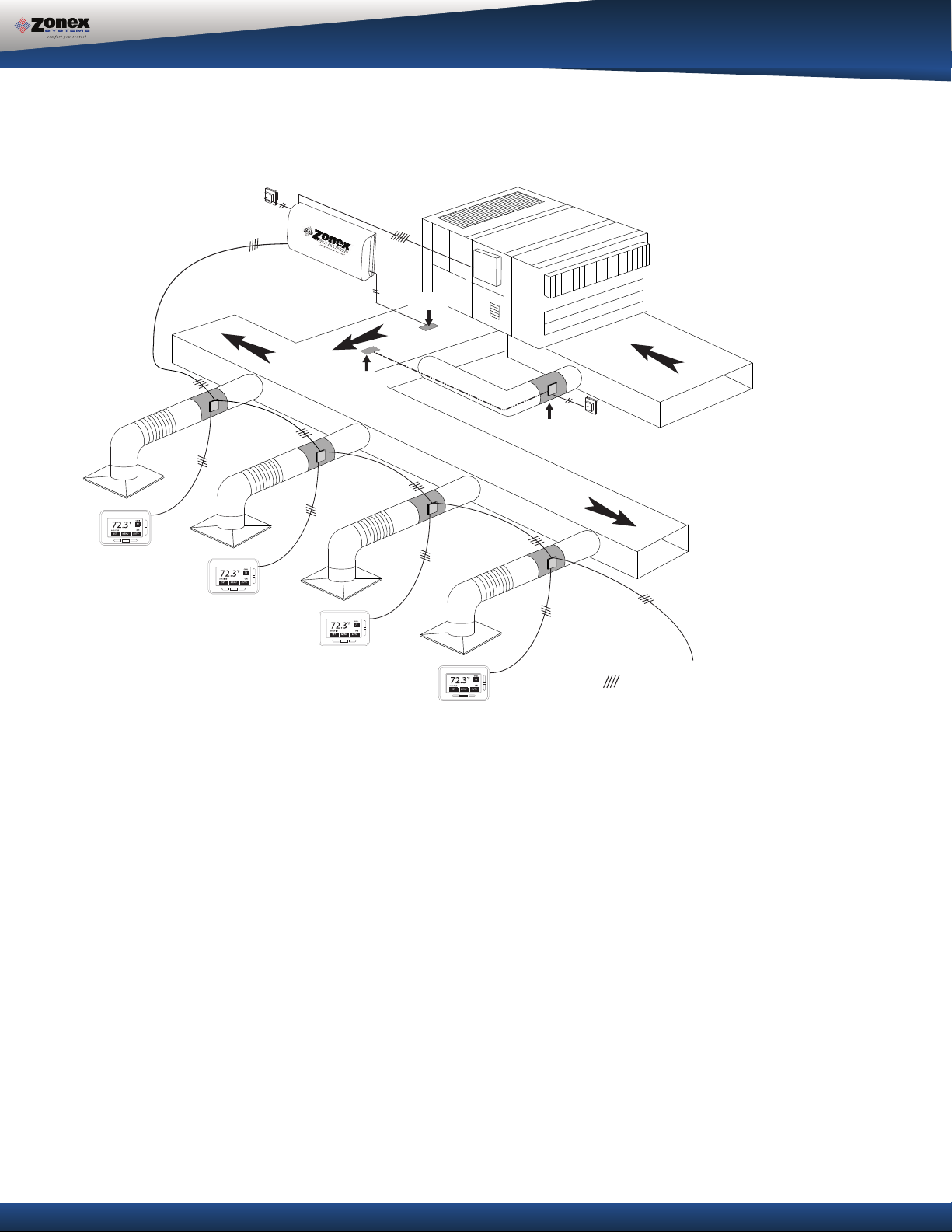
SYSTEM OVERVIEW
System Features
- Universal for G/E or H/P Units
- 2 or 3 Wire Zone Dampers
- Up to 10 Zones Per Unit
- Auto- Changeover Operation
- On-board Capacity Control
- Start Up Diagnostic
- 2 Data Wires
- 2 Power Wires
- 4 Wire Stat to Damper Board
- No Home Run Wiring
- No Computer Required For Setup
UP TO 10 DAMPERS
PULL 24V POWER AND UNSHIELDED TWISTED PAIR
DAISY CHAINED FROM DAMPER TO DAMPER
SYSTEM OVERVIEW
The GEN II-R is a residential / light commercial zone control system controlling 2-10 independent
zones per unit. The GEN II-R controller is designed for auto changeover, multi-stage Heat Pump
(2C/3H) and Gas Electric (2C/2H) applications.
The GEN II-R system uses field supplied programmable thermostats, which power and control the
24-volt, power open / power closed or power closed / spring open round and rectangular dampers.
Additional features include LED status indication of all system functions, digital LAT display, fully
adjustable capacity control with on-board limit settings, and optional staging strategies.
The system provides the installing contractor with a simple startup diagnostic to minimize wiring errors
and speed installation.
1

COMPONENT SELECTION GUIDE
GEN II -R
Universal Controller for
Gas/Electric - 2-Stage Heat/Cool
or
Heat Pump 3- Stage Heat/2-Stage Cool
Includes Leaving Air Sensor (LAT)
GAS/ELECTRIC
PROGRAMMABLE
Field Supplied
5 TONS AND UNDER
Low Pressure Dampers (12VA)
Round - (TRX size) up to .5” SP
Rect. Single Blade - (TREX W x H) up to .5” SP
Rect. Opposed Blade - (TREX W x H) up to .5” SP
DAMPER TRANSFORMER***
ZONE DAMPERS
Heavy Duty Rectangular - (**STCRX W x H) up to 1.75” SP
HEAT PUMP*
HEAT PUMP THERMOSTATSGAS/ELECTRIC THERMOSTATS
PROGRAMMABLE
Field Supplied
OVER 5 TONS
Medium Pressure Dampers (2VA)
Round - (**STMRX size) up to 1.75” SP
**
BYPASS DAMPERS
5 TONS AND UNDER
BAROMETRIC BYPASS
Round - (101ABBD diam)
Rectangular ( RBB W x H)
ELECTRONIC MODULATING BYPASS DAMPER
(Includes Integrated Static Pressure Control)
Rectangular ( STCDBP size) up to 1.75” SP
1-24 40VA Transformer Powers Bypass
OVER 5 TONS
BYPASS DAMPER
Round - (STBP size) up to 1.75” SP
COMPLETE SYSTEM
*Note: For Heat Pump systems using Gas/Electric inputs ( no “O” or “B” reversing value circuits) use the Gas/Electric set up.
** Note: For Heat Pump operation with emergency heat, install one Heat Pump thermostat with emergency heat operation on any zone.
*** Note: Damper transformer needs to be sized based on the VA of the style and quantity of the dampers. See page 19 for transformer sizing.
2

GENERAL SEQUENCE OF OPERATION
GENERAL SEQUENCE OF OPERATION
When the GEN II-R controller is powered up, the total number of addressed dampers are determined and
verified on the display. This confirms the controller is communicating with all dampers in the system. If
there are no active heat or cool calls detected, the supply dampers will open in ventilation mode. The
system blower operation can be configured for constant ON or intermittent Auto.
The GEN II-R systems can be field configured for adjustable time based opposing call changeover or vote
based majority changeover. The GEN II-R controller is shipped from the factory for 10-minute opposing
call changeover. The GEN II-R controller “polls” the damper control boards once per minute to determine
the thermostat demand status for heat and cool. The heat and cool changeover functions will operate
according to changeover strategy selected. When the GEN II-R controller changes modes, a 5-minute
purge cycle is initiated before the changeover is completed.
On active heat or cool calls, the non-calling zones will close. When the last calling zone is satisfied in
either heat or cool mode, the GEN II-R controller terminates the HVAC outputs after the next “poll” and
the blower output will be de-energized (unless controller is configured for constant fan) for a 5-minute
purge cycle. During the purge cycle no heat or cool calls are recognized.
When the system is in the heating mode and calls for cooling are received, an opposing call timer strategy
operates. This timer is adjustable from 5 - 30 minutes. The factory default is 10 minutes. At the end of the
selected time period, if the opposing call is 3° away from set point, heating is turned off. After a 5-minute
purge mode, Cooling is turned on until the cool call is satisfied. If necessary, GEN II-R will return to the
heating mode, If all calls have been satisfied, dampers will open for ventilation. If the opposing zone strategy is not desired, this feature may be disabled.
3

LEGEND
TERMINAL FUNCTIONS / CONNECTIONS
GAS ELECTRIC OPERATION
D
GEN II-R
OFF ON
TR1
OUT IN
A
B
C
TR2
TR1TR2
TC TC
Y1Y2W1W2G
R
GE
O/B RY1Y2G W2
HP
G
E
F
EH
O/BHPPRI
SET
TIME/TMP
TIME
ON
AUTO
H
UP
DN
7 2
I
Y1
A / B - Data Transmit / Receive
S S – Leaving / Supply Air Sensor Input
G – Fan Output
W2 –
W1 –
Y2 – Stage 2 Cool Output
Y1 – Stage 1 Cool Output
R – 24vac from Unit Transformer
TC / TC – Not Used
TR1 / TR2 – 24vac Power Input / Common
Y2
Stage 2 Heat Input
Stage 1 Heat Input
TR1 / TR2 - Damper Power Daisy Chain
Damper to Damper (18GA Thermostat wire)
W1
W2
NIGHT DAY
UNLOCK LOCK
K
J
A
G
GND B
S S
L
M
TR1 & TR2 Power out to Dampers R & C
A
(18 ga thermostat wire)
B TR1 & TR2 24-Volt Transformer
C Not Used
D Unit Terminals
E On / Off Switch
F Priority Jumper (Not Used)
H/P Jumper (Jump for Heat Pump
Operation)
O/B Jumper (Heat Pump Only –
Reversing Valve Operation)
EH Jumper (Set Up Fan Operation for
Electric Heat)
G Digital Display (Leaving Air Temperature
and configuration)
H Up / Down / Set Buttons (High Limit, Low
Limit, Set)
I Fan Jumper (Continuous or Auto)
Staging Strategy (Time / Temperature or
nly)
Time O
J Not Used
K Not Used
A / B / GND Communications Wire
L
M S S Terminals – Leaving Air Sensor (LAT)
General Installation Instructions
GEN II-R Controller
1. Install the GEN II-R controller on an interior wall where the ambient temperature is between 32°120°F (0°- 48°C) non-condensing. This controller is to be installed in an accessible interior
area; not in attics or above ceilings.
2. The controller is to be powered by a dedicated
style and quantity.
The secondary voltage to the controller must be 24 to 28vac.
3. Install the leaving air sensor (LAT) in the supply air, ahead of the bypass take-off. Sensor wires
are connected to the S S terminals on the controller (M). The LAT sensor leads may be
extended using standard 18/2 thermostat wire.
4. The leaving air sensor (LAT) is calibrated to the controller at the factory. However, the
calibration should be checked as part of the system setup procedure. If adjustments are
required, use the Blue potenti
GEN II-R controller. Screw the pot clockwise to lower the display temperature and counter clockwise to raise the temperature. NOTE: The display will update every 10 seconds.
5. Confirm you have daisy chained the A and B communication wires and R and C from the
damper control boards to the GEN II-R controller (A & L), A=(TR1, TR2), L=(A, B). (Communi cation wire maximum is 4,000 ft. from the GEN II-R controller to the farthest damper).
6. Connect the output wires from the controller to the HVAC system using standard 18 GA
thermostat wire.
24vac 40va transformer. VA based on damper
The transformer secondary is wired to TR1 TR2 on the controller (B).
ometer labeled R44 located in the upper right hand corner of the
4

GAS ELECTRIC BASIC CONTROLLER CONFIGURATION
The GEN II-R is equipped with a Digital Display (G) that constantly displays Leaving
Air Temperature from the unit. The display and 3 buttons beneath the display provide the
installing contractor the ability to tailor the system to your specific application.
The GEN II-R controller is shipped from the factory configured for basic Gas/Electric operation.
However, the following should be checked as part of the initial installation setup procedures:
1. EH jumper (F) is i
is controlled by the HVAC system fan control. When a fan output is required from the GEN II-R
controller on a call for heat, place the EH jumper over both pins for several seconds and then
remove. Place the jumper tab on one pin.
2. O/B and HP jumpers (F) should both be on one pin or removed, for GE operation.
3. PRIORITY jumper (F) should be on one pin.
4. Set the power switch (E) to ON
5. Set the NIGHT DAY switch (J) to the DAY position.
6. Set the fan jumper (I) to AUTO for intermittent operation or ON for constant ON operation in the
Occupied mode.
7. Place the LOCK – UNLOCK switch (K) in the UNLOCK position.
8. Place the TIME/TEMP jumper (I) on the middle and upper pins to control Y2 and W2 staging on
run time and supply air temperature.
nstalled by the factory on one pin for normal gas heat operation where the fan
.
GEN II-R Gas Electric Advanced Feature Configuration
Gas Electric Capacity Control - Cool and Heat cut-out temperature adjust
The factory setting for the Cool and Heat cut-out temperatures is 45°- 145°F (7°- 62°C). This can
be easily changed with the following procedure:
1. Cool cut-out temp – Press the DN button (H); “C” will be displayed and then the cut-out
temperature.
2. LOWER – Press the DN button; after the “C” is displayed, continue to hold the DN button until
the desired temperature is displayed; then
NOTE: The controller will not change the Cool cut-out lower than 40°F (4°C).
3. RAISE–Press the DN button; after “C” is displayed, immediately release the DN button and
press the UP button. Hold until the desired temperature reading is displayed and release.
4. Press the DN button to verify the new cool cut-out temperature.
release.
Heat cut-out temperature - Press and hold the UP button; after the “H” is displayed, use the
same procedure as above to raise
or lower the displayed temperature.
Electric Heat - Fan Configuration
EH jumper (F) is installed by the factory on one pin for normal gas heat operation where the fan is
controlled by the HVAC system fan control. When a fan output is required from the GEN II
controller on a call for heat, place the EH jumper over both pins for several seconds and then
remove. Place the jumper tab on one pin.
2nd Stage Heat and Cool Cut-in / Cut-out Configuration
The GEN II-R controller is set up at the factory to stage Y2 and W2 cut-in operation based on a 3-minute time delay and supply air temperature. This is done using the TIME/TEMP (I) jumper. Time may
be field configured from 3-20 minutes by the contractor during system configuration. The cut-in
temperatures are fixed in the controller program at 58°F (14°C) and higher for Y2 and 120°F (48°C)
and lower for W2. The GEN II-R controller second stage cut-out temperature is fixed in the controller
program at 50°F (10°C). Y2 will de-energize when it drops below 50°F and re-energize when it rises
above 58°F. If the air temperature drops below the low cut-out (45°F) Y1 and Y2 are de-energized and
the controller will go into a 5 minute purge mode. After 5 minute purge, if the temperature has risen
above the low cut-out Y1 is re-energized. Heat W1 and W2 will de-energize if leaving air temperature
rises above heat cutout and will be locked out for 5 minutes. After 5 minute lockout, if a heat call
remains and leaving air temperature is lower than heat cutout, W1 will re-energize. By placing jumper
on bottom two pins, a time only strategy may be configured into the system. ( see below);
5

GAS ELECTRIC ADVANCED FEATURE CONFIGURATION
Adjust 2ndStage Cut-in Time Delay
1. To increase the Y2 and W2 cut-in delay, press and hold the SET and DN buttons (H)
simultaneously. When 03 appears in the display, release the buttons and immediately press
the UP button and hold until the desired delay time is displayed, and release. The time delay
is fully adjustable from 3 - 20 minutes. To verify the change, press and hold the SET and DN
buttons simultaneously until the delay time is shown, and relea
2. To decrease the Y2 and W2 cut-in delay, press and hold the SET and DN buttons (H)
simultaneously. When delay time appears in the display, release the buttons and immediately
press the DN button and hold until the desired delay time is displayed, and release. To verify
the change, press and hold the SET and DN buttons until the delay time is shown, and release.
Configure 2ndStage Cut-in for Time Delay and Thermostat Demand Only
1. Place the 2ndstage configuration jumper (I) on the middle and lower pins - TIME.
2. If the cut-in time delay must be changed from the factory setting of 03 (3 min), follow the above
procedures to raise or lower the time delay value.
3. Verify time delay value by pressing the SET and DN buttons simultaneously.
se.
6

LEGEND
HEAT PUMP OPERATION
TERMINAL FUNCTIONS / CONNECTIONS
HEAT PUMP OPERATION
GEN II-R
OFF ON
TR1
OUT IN
A
B
C
D
TR2
TR1TR2
TC TC
Y1Y2W1W2G
R
GE
G
E
F
EH
O/BHPPRI
O/B RY1Y2G W2
Y1
HP
A / B - Data Transmit / Receive
S S – Leaving / Supply Air Sensor Input
G – Fan Output
W2 – Auxiliary / Emergency Heat
O/B – Reversing Valve Output
Y2 – Stage 2 Cool Output
Y1 – Stage 1 Cool Output
R – 24vac from Unit Transformer
TC / TC – Not Used
TR1 / TR2 – 24vac Power Input / Common
TR1 / TR2 - Damper Power Daisy Chain
Damper to Damper (18GA Thermostat wire)
Y2
SET
TIME/TMP
TIME
AUTO
H
UP
DN
ON
I
W1
W2
7 2
NIGHT DAY
UNLOCK LOCK
K
J
A
G
GND B
S S
A
TR1 & TR2 Power out to Dampers R & C
(18 ga thermostat wire)
B TR1 & TR2 24-Volt Transformer
C Not Used
D Unit Terminals
E On / Off Switch
F Priority Jumper (Not used)
H/P Jumper (Jump for Heat Pump
Operation)
O/B Jumper (Heat Pump Only –
Reversing Valve Operation)
L
EH Jumper (Set Up Fan Operation for
Electric Heat)
G Digital Display (Leaving Air Temperature
M
and configuration)
H Up / Down / Set Buttons (High Limit,
Low Limit, Set)
I Fan Jumper (Continuous or Auto)
Staging Strategy (Time / Temperature or
Time Only)
J Not Used
K Not Used
L A / B / GND Communications Wire
M S S T
erminals – Leaving Air Sensor
(LAT)
General Installation Instructions
GEN II-R Controller
1. Install the GEN II-R controller on an interior wall where the ambient temperature is between 32°120°F (0°- 48°C) non-condensing. This controller is to be installed in an accessible interior
area; not in attics or above ceilings.
2. The controller is to be powered by a dedicated
style and quantity. The transformer secondary is wired to TR1 TR2 on the controller (B).
The secondary voltage to the controller must be 24 to 28vac.
3. Install the LAT air sensor in the supply air between
elements. The LAT sensor leads may be extended using standard 18/2 thermostat wire.
4. The leaving air sensor (LAT) is calibrated to the controller at the factory. However, the
calibration should be checked as part of the system setup procedures. If adjustments are
required, use the Blue potentiometer labeled R44 located in the upper left hand corner of the
GEN II-R controller. Screw the pot clockwise to lower the display temperature and counter clockwise to raise the temperature.
5. Confirm you have daisy chained the A and B communication wires and R and C from the
Damper control boards to the GEN II-R controller (A & L), A=(TR1, TR2), L=(A, B). (Communi cation wire maximum is 4,000 ft. from the GEN II-R controller to the farthest damper).
6. On each damper board place the HP jumper on both pins for Heat Pump operation.
7. Connect the output wires from the controller to the HVAC system using standard 18 GA
thermostat wire.
24vac 40va transformer. VA based on damper
the indoor coil and electric strip heat
NOTE: The display will update every 10 seconds.
7

GENERAL INSTALLATION INSTRUCTIONS
Heat Pump operation “O” reversing valve
Cool Call – When a majority active cool call is received by the GEN II controller, Y1, O/B and G
LEDs are illuminated; and the outputs are energized (within 1.5 to 3 minutes). After 3 minutes, if
the leaving air temperature is 58°F (14°C) or above, Y2 will energize for 2-stage systems. Y2 will
de-energize when it drops below 50°F and re-energize when it rises above 58°F. If the supply air
temperature drops one degree below the Cool cut
for 5 minutes.
“B” reversing valve –
Sequence of operation is the
Heat Call - When a majority active heat call is received by the GEN II controller, Y1 and G LEDs are
illuminated; and the outputs are energized (within 1.5 to 3 minutes). If after 3 minutes the leaving
air temperature is 94°F (34°C) or less, Y2 will energize. If after 6 minutes of run time the leaving air
temperature is 91°F (32°C) or less, W2 will energize. If the supply air temperature exceeds 126°F
(52
°C), Y1, Y2 and W2 (if energized) will drop out; and Y1 can then energize after a 5-minute time
delay. NOTE: If the system fan is configured for “AUTO” on the GEN II controller, the “G” output
will be de-energized in the temperature cut-out mode.
When the last active call satisfies, the GEN II controller goes into a 5-minute purge cycle with all
supply dampers closing; then all dampers modulate open for ventilation.
Heat Pump operation “B” reversing valve
-out temperature, Y1 and Y2 will de-energize
same: O/B is energized in the heat mode.
By placing the O/B jumper (B) on both pins, the GEN II controller is configured for “B” reversing
valve operation. The operation and setup procedures are the same as with “O” mode reversing
valve, except the reversing valve will be energized for heat operation.
GEN II-R Heat Pump Basic Configuration
The GEN II-R controller is shipped from the
factory for Gas Electric operation.
The controller must be field configured for
Heat Pump operation.
Heat Pump configuration:
1. Switch controller to OFF (E).
2. Set the O/B jumper (F) on one pin for “O”
reversing valve (energizes for cool) or
A
B
C
TR1
TR2
TR1TR2
TC TC
OFF ON
OUT IN
E
F
Set the O/B jumper (F) on both pins for “B”
reversing valve (energizes for heat).
Y1Y2W1W2G
R
GE
O/B RY1Y2G W2
Y1
HP
3. Set the HP jumper (F) on both pins for Heat
Pump operation.
4. Set the Priority jumper (F) on one pin.
5. Set the TIME / TEMP jumper (I) on the
middle and upper pins.
D
6. Set NIGHT / DAY switch (J) for DAY position.
7. Set LOCK / UNLOCK switch (K) to UNLOCK.
8. Swi
tch the controller to ON (E).
9. Press the UP button (H), and verify the “H” (cut-out) temperature reads 126°F (52°C) on the
controller display (G).
NOTE: The heat cut-out temperature
must not be changed from the factory setting.
GEN II-R
SET
EH
O/BHPPRI
TIME/TMP
TIME
Y2
AUTO
G
H
UP
DN
ON
7 2
I
W1
W2
NIGHT DAY
UNLOCK LOCK
K
J
A
G
GND B
S S
L
M
8

HEAT PUMP ADVANCED FEATURE CONFIGURATION
GEN II-R Heat Pump Advanced Feature Configuration
Heat Pump Capacity Control - Cool and Heat cut-out temperature adjustment
When the GEN II-R controller is configured for Heat Pump (HP jumper (F) on both pins), the Cool /
Heat cut-out temperatures are 45°- 126°F (7°- 52°C). The cut-out temperatures can be changed
with the following procedure:
Heat cut-out temp – To eliminate the possibility of the Heat Pump tripping out on high head
pressure or short cycling in the heat mode, the heat cut-out temperature should never
from the factory setting of 126°F (52°C).
1. Cool cut-out temp – Press the DN button (H); “C” will be displayed, then the cut-out
temperature.
2. LOWER – Press the DN button. After the “C” is displayed, continue to hold the DN button until
the desired temperature is displayed; then release.
NOTE: The controller will not change the Cool cut-out lower than 40°F (4°C).
3. RAISE – Press the DN button. After “C” is displayed, immediately release the DN button, and
press the UP button. Hold until the desired temperature reading is displayed; then release.
4. Press the DN button to verify the new cool cut-out temperature.
2nd Stage Heat and Cool Cut-in / Cut-out Configuration
The GEN II-R controller is set up at the factory to stage Y2 and W2 cut-in operation based on a 3-minute time delay and supply air temperature. This is done using the TIME/TEMP (I) jumper. Time may
be field configured from 3-20 minutes by the contractor during system configuration. The cut-in
temperatures are fixed in the controller program at 58°F (14°C) and higher for Y2 and 120°F (48°C)
and lower for W2. The GEN II-R controller second stage cut-out temperature is fixed in the controller
program at 50°F (10°C). Y2 will de-energize when it drops below 50°F and re-energize when it rises
above 58°F. If the air temperature drops below the low cut-out (45°F) Y1 and Y2 are de-energized and
the controller will go into a 5 minute purge mode. After 5 minute purge, if the temperature has risen
above the low cut-out Y1 is re-energized. Heat W1 and W2 will de-energize if leaving air temperature
rises above heat cutout and will be locked out for 5 minutes. After 5 minute lockout, if a heat call
remains and leaving air temperature is lower than heat cutout, W1 will re-energize. By placing jumper
on bottom two pins, a time only strategy may be configured into the system. ( see below);
be changed
Adjust 2ndStage Cut-in Time Delay
1. To increase the Y2 and W2 cut-in delay, press and hold the SET and DN buttons (H)
simultaneously. When 03 appears in the display, release the buttons and immediately press
the
UP button and hold until the desired delay time is displayed, and release. The time delay
is fully adjustable from 3 - 20 minutes. To verify the change, press and hold the SET and DN
buttons simultaneously until the delay time is shown, and release.
2. To decrease the Y2 and W2 cut-in delay, press and hold the SET and DN buttons (H)
simultaneously. When delay time appears in the display, release the buttons and immediately
press the DN button and hold until the desired
the change, press and hold the SET and DN buttons until the delay time is shown, and release.
delay time is displayed, and release. To verify
Configure Y2 and W2 Cut-in for Time Delay and Thermostat Demand Only
nd
1. Place the 2
2. If the Y2 cut-in time delay must be changed from the factory setting of 03 (3 min), follow the
above procedures to raise or lower the time delay value.
NOTE: The cutcontrol program and cannot be manually changed.
3. Verify time delay value by pressing the SET and DN buttons simultaneously.
stage configuration jumper (I) on the middle and lower pins - TIME.
in delay timing for W2 (Aux Heat) is set for approximately 3 minutes in the
9

DAMPER CONTROL BOARD CALL OUT AND CONFIGURATION
A
A
B
B
RC
MC
RO
HP
A
A
B
B
RC
MC
RO
ZN1
ZN2
ZN3
ZN4
ZN5
ZN6
ZN7
ZN8
ZN9
ZN10
RUN OPEN
RUN CLOSED
HP
DAMPER CONTROL BOARD LEGEND
A R & C 24 volt Power Daisy Chained IN and OUT
B Thermostat Terminals
C Damper Board ID
D Jumper for Heat Pump Operation
E Damper Motor Terminals
F Data Transmit / Receive IN
G Date Transmit / Receive OUT
TERMINAL FUNCTIONS / CONNECTIONS
R / C - 24 volt Power IN and OUT
R - 24 volt Hot to Thermostat
C - 24 volt Common to Thermostat
W/OB - Heating Input / Reversing Valve Input
Y - Cooling Input
E - Emergency Heat Input (Heat Pump Only)
MC - Motor Common
RO - Run Open
RC - Run Closed
A / B - Data Transmit / Receive IN and OUT
A
B
R
C
R
C
W/OB
Y
C
E
ZN1
ZN2
ZN3
ZN4
ZN5
ZN6
RUN OPEN
RUN CLOSED
ZN7
ZN8
ZN9
ZN10
D
HP
MC
RO
RC
B
A
A
E
F
B
G
DAMPER CONTROL BOARD ADDRESSING / CONFIGURATION
Each damper control board must have a unique address from 1-10. To set the damper control board address there is a
jumper on the board. Find the first damper in the daisy chain and place the jumper on ZN1 for address #1. Go to the
second damper in the daisy chain and place the jumper on ZN2 for address #2. Continue addressing the damper control
boards in numerical order of the daisy chain wiring.
HP
MC
RO
RC
B
A
B
A
R
C
Setting Damper Boards for Heat Pump Operation
When the GEN II-R controller is set up for Heat Pump operation, every damper board in the system needs to be
placed in heat pump mode. This allows the dampers boards to work with heat pump thermostats. Place the HP
jumper on both pins.
R
C
W/OB
Y
E
ZN1
ZN2
ZN3
ZN4
ZN5
ZN6
RUN OPEN
RUN CLOSED
ZN7
ZN8
ZN9
ZN10
10

THERMOSTAT WIRING SCHEMATIC
THERMOSTAT SELECTION BASED ON SYSTEM OPERATION
All thermostats are field selected, make sure to choose a programmable thermostat for each zone based on the system
parameters below. Programmable thermostats allow multiple schedules on a zone by zone basis.
GAS / ELECTRIC - Use any standard gas / electric single stage Heat / Cool 7 day programable thermostat.
HEAT PUMP - Use any standard heat pump single stage Heat / Cool 7 day programable thermostat.
Note: For heat pump operation with emergency heat, install one heat pump thermostat with emergency
heat operation on any zone.
WIRING TO A GAS / ELECTRIC THERMOSTAT
R
C
W
Y
70.9
°F
71
WIRING TO A HEAT PUMP THERMOSTAT
R
C
OB
Y
E
70.9
°F
71
R
C
R
C
W/OB
Y
E
ZN1
ZN2
RUN OPEN
RUN CLOSED
ZN5
ZN6
ZN7
ZN8
ZN3
ZN4
DAMPER CONTROL BOARD
R
C
R
C
W/OB
Y
E
ZN1
ZN2
RUN OPEN
RUN CLOSED
ZN5
ZN6
ZN7
ZN8
ZN3
ZN4
DAMPER CONTROL BOARD
MC
RO
RC
B
A
B
HP
ZN10
ZN10
A
MC
RO
RC
B
A
B
HP
A
ZN9
ZN9
Note: For heat pump operation with emergency heat, install one heat pump thermostat with emergency
heat operation on any zone.
11

DESCRIPTION
A
A
B
B
ZN1
ZN2
ZN3
ZN4
ZN5
ZN6
ZN7
ZN8
ZN9
ZN10
HP
GEN II-R WIRING SCHEMATIC WITH PC / SO DAMPERS
PER RTU OR SPLIT SYSTEM
GEN II CONTROLLER CONTROLS 2-10 ZONE DAMPERS
ONLY 1 24VAC 40VA TRANSFORMER POWERS ALL SUPPLY
ID
DAMPERS AND THERMOSTATS
C1
FIELD SUPPLIED 7 DAY PROGRAMMABLE THERMOSTATS
24VAC/40VA TRANSFORMER SIZED @ (12VA PER ZONE DAMPER)
DM POWER CLOSED, SPRING OPEN DAMPER (FACTORY PRE-WIRED)
TR1
DEVICE
THERMOSTAT T1 -T10
ZONE DAMPER
CONTROL BOARD
SYSTEM TRANSFORMER
GEN II-R
WITH POWER CLOSED / SPRING OPEN DAMPERS
RESIDENTIAL / LIGHT COMMERCIAL ZONING - CONTROL 2-10 ZONES
DAISY CHAIN DAMPER TO DAMPER
SUPPLY LAT LOCATED BEFORE THE BYPASS
LAT
SUPPLY LAT DISCHARGE SENSORS
UNLOCK LOCK
NIGHT DAY
JUMPER ON BOTH PINS FOR HEAT PUMP OPERATION
BAROMETRIC BYPASS USED ON SYSTEMS 5 TONS OR LESS
HP
BP-DM
HEAT PUMP OPERATION
BYPASS DAMPER
24V POWER IN AND OUT USE 18/2 THERMOSTAT WIRE
A
TWISTED PAIR WIRING -BELDEN 8740 DAISY CHAIN
RS485 COMMUNICATION LINK
DAMPER TO DAMPER
GND B
FOR APPLICATIONS ASSISTANCE CALL 800-228-2966
VISIT OUR ON-LINE CATALOG AT ZONEXPRODUCTS.COM
S S
ZONE ID ADDRESS JUMPERS
AND HEAT PUMP OPERATION JUMPER
MC
R
MC
R
RO
RUN OPEN
RUN CLOSED
C
RO
RUN OPEN
RUN CLOSED
C
C
C
C
C
FIELD SUPPLIED THERMOSTATS
DAISY CHAIN 24VAC AND DATA LINK CABLE (BELDEN 8740)
TO ALL ZONE DAMPER BOARDS - EXPANDABLE TO 10 ZONES
B
B
A
A
RC
HP
ZN10
ZN9
ZN8
ZN7
ZN6
ZN5
DM-3
ZN4
ZN3
ZN2
ZN1
R
C
W/OB
B
A
RC
R
C
W/OB
ZONE DAMPER
Y
E
B
A
HP
ZN10
ZN9
ZN8
ZN7
ZN6
ZN5
DM-2
ZN4
ZN3
ZN2
ZN1
ZONE DAMPER
Y
E
GAS / ELECTRIC OR HEAT PUMP OPERATION.
USE 7 DAY PROGRAMMABLE THERMOSTATS FOR
FOR HEAT PUMP OPERATION WITH EMERGENCY HEAT,
70
°F
69.3
74
°F
74.6
INSTALL ONE HEAT PUMP THERMOSTAT
WITH EMERGENCY HEAT OPERATION ON ANY ZONE.
T3
T2
G
7 2
DN
UP
ON
SET
TIME/TMP
EH
O/BHPPRI
R = TR1 C = TR2
Power Terminals
OFF ON
TR2
TR1
24V POWER OUT
24V POWER IN
TR1TR2
TC TC
C1
W2
W1
AUTO
TIME
Y2
Y1
O/B RY1Y2G W2
HP
GE
Y1Y2W1W2G
R
MC
R
RO
RUN OPEN
RUN CLOSED
C
B
B
A
A
RC
HP
HP
ZN10
ZN9
ZN8
ZN7
ZN6
ZN5
DM-1
ZN4
ZN3
ZN2
ZN1
R
C
W/OB
ZONE DAMPER
Y
E
71
°F
C
C
T1
70.9
12

A
A
B
B
ZN1
ZN2
ZN3
ZN4
ZN5
ZN6
ZN7
ZN8
ZN9
ZN10
HP
GEN II-R WIRING SCHEMATIC WITH PC / PO DAMPERS
DESCRIPTION
IND. 24VAC/40VA TRANSFORMER
GEN II CONTROLLER
CONTROLS 2-10 ZONE DAMPERS
ONLY 1 24VAC 40VA TRANSFORMER*
POWERS ALL SUPPLY DAMPERS
AND THERMOSTATS
TO POWER THE BYPASS DAMPER
SUPPLY LAT LOCATED BEFORE
POWER CLOSED, POWER OPEN
DAMPER (FACTORY PRE-WIRED)
24VAC/40VA TRANSFORMER
SIZED @ (2VA PER ZONE DAMPER)
FIELD SUPPLIED THERMOSTAT
DAISY CHAIN DAMPER TO DAMPER
THE BYPASS. RETURN LAT
LOCATED AFTER THE BYPASS
LOCATED AFTER THE BYPASS
BEFORE THE FIRST SUPPLY TAKEOFF
JUMPER IN PLACE FOR HEAT PUMP
OPERATION
TWISTED PAIR WIRING -BELDEN 8740
SUPPLIED WITH BYPASS
SUPPLIED WITH THE BYPASS
DAMPER (FACTORY PRE-WIRED)
DAMPER (FACTORY PRE-WIRED)
DAISY CHAIN DAMPER TO DAMPER
ID
DEVICE
CONTROL BOARD C1
THERMOSTAT T1 -T10
DM
ZONE DAMPER
TR1
SYSTEM TRANSFORMER
BYPASS TRANSFORMER TR2
IPC
LAT
SPT
INTEGRATED
SUPPLY / RETURN AIR
STATIC PRESSURE CONTROL
LAT DISCHARGE SENSORS
STATIC PRESSURE TUBE
HP
BP-DM
DAISY CHAIN 24VAC AND
EXPANDABLE TO 10 ZONES
DM-3
ZONE DAMPER
DATALINK CABLE (BELDEN 8740)
TO ALL ZONE DAMPER BOARDS -
C
C
FIELD SUPPLIED THERMOSTATS
USE 7 DAY PROGRAMMABLE THERMOSTATS FOR
70
°F
INSTALL ONE HEAT PUMP THERMOSTAT
GAS / ELECTRIC OR HEAT PUMP OPERATION.
WITH EMERGENCY HEAT OPERATION ON ANY ZONE.
FOR HEAT PUMP OPERATION WITH EMERGENCY HEAT,
T3
69.3
ZONE ID ADDRESS JUMPERS
FOR APPLICATIONS ASSISTANCE CALL 800-228-2966
HEAT PUMP OPERATION
BYPASS DAMPER ACTUATOR
24V POWER IN AND OUT USE 18/2 THERMOSTAT WIRE
VISIT OUR ON-LINE CATALOG AT ZONEXPRODUCTS.COM
RS485 COMMUNICATION LINK
AND HEAT PUMP OPERATION JUMPER
ACTUATOR
B
B
A
A
RC
RO
MC
HP
ZN10
ZN9
RC
RO
MC
R
RUN OPEN
RUN CLOSED
C
ZN8
ZN7
ZN6
ZN5
ZN4
ZN3
ZN2
ZN1
R
Y
C
W/OB
E
T2
C
C
74
°F
C
74.6
T1
71
°F
C
70.9
13
B
B
A
A
RC
RO
MC
HP
ZN10
ZN9
RC
RO
GEN II-R
WITH POWER CLOSED / POWER OPEN DAMPERS -3 WIRE
UNLOCK LOCK
NIGHT DAY
A
RESIDENTIAL / LIGHT COMMERCIAL ZONING - CONTROL 2-10 ZONES
7 2
DN
UP
ON
TC TC
TIME/TMP
EH
O/BHPPRI
AUTO
TIME
O/B RY1Y2G W2
SET
R = TR1 C = TR2
Power Terminals
OFF ON
TR2
TR1
24V POWER OUT
24V POWER IN
TR1TR2
S S
GND B
G
W2
W1
Y2
Y1
HP
GE
Y1Y2W1W2G
R
ACTUATOR
ACTUATOR
MC
R
MC
RC
RO
MC
R
RUN OPEN
RUN CLOSED
C
RO
RUN OPEN
RUN CLOSED
C
ZN8
ZN7
ZN6
ZN5
DM-2
ZN4
ZN3
ZN2
ZN1
R
C
W/OB
B
A
RC
R
C
W/OB
ZONE DAMPER
Y
E
B
A
HP
HP
ZN10
ZN9
ZN8
ZN7
ZN6
ZN5
DM-1
ZN4
ZN3
ZN2
ZN1
ZONE DAMPER
Y
E

SYSTEM START UP AND TEST
System Start Up and Test
1. Plug all thermostats into sub-bases. Turn GEN II-R power switch (E) to ON.
2. Find the first damper control board in the Daisy chain and set its address to 01.
3. Turn GEN II-R power switch OFF and then ON. The Display should flash 01 and then show the
leaving air temperature. This confirms your successful wiring and communication with that
thermostat.
4. If 01 is displayed, change the next damper control board address to 02. Turn the GEN II-R
switch OFF and then ON. Th e display should flash 02 and then show the tem
address damper control boards one at a time.
5. After each damper board is re-addressed, turn the power switch OFF and then ON. This will
verify that the re-addressed damper board has been found by the GEN II-R Controller.
This procedure will simplify your installation and will confirm your wiring is correct and that the GEN
controller can communicate over the 2-wire twisted pair data link with every thermostat in your
II-R
system.
Troubleshooting
When stat #1 is not found:
perature. Re -
1. Check damper control board to verify that it is addressed as 01.
2. Check all TR1 and TR2 wiring for proper color-to-color connections. Even if the stats are powered
all R wires at the damper control board must be connected to the GEN II-R TR1 terminal. All C wires
must be connected to the GEN II-R TR2 terminal. Confirm the daisy chain wiring is correct at this
time.
3. Check A, B wires for proper color code and connections; polarity is imperative. All A connec tions must land on A terminal on each of damper control board, and all B connections must connect
to B terminal on each damper control board.
4. Check TR1 and TR2 wires for opens or shorts.
Checking the Daisy Chain for opens or shorts:
Start from the GEN II-R board, and follow A, B wires to the first damper control board. Remove the A,
B wires going to the next damper control board in the link and address the first damper control board
as #1. Turn the GEN II-R power switch Off, then On, to see if the display flashes 01, at the GEN II-R
controller.
1. If 01 is displayed, the first link of the daisy chain is OK. Reconnect the wires going to sub-base.
2. Repeat these steps with a stat numbered 02. If the number 02 is displayed, then communication is
confirmed.
When the correct number does not appear for a link, that link is either shorted or open. A link of the
daisy chain, which is open or shorted, must be repaired before the next damper is checked.
When the damper control boards are correctly addressed, wired and linked, the total number of stats
on your job connected to the GEN II-R control board will be displayed when the board is turned on.
After the correct number of connected damper control boards is displayed, complete the wiring of the
AC unit or heat pump connections, next make heat and cool calls to the GEN II-R controller.
14

ADVANCED FEATURE CONFIGURATION
Fan operation
The factory setting for FAN operation is AUTO, with the FAN jumper (I) on the middle and lower
pins. In this setting, the fan circuit on “G” is only energized on an active cool call in Gas/Electric
mode or on an active heat call or cool call in Heat Pump mode.
When the FAN jumper is in AUTO, there is no output on “G” with an active heat call in Gas/Elec-
tric mode. For constant fan operation place the FAN jumper (I) on the center and upper pins on ON.
Opposing Call Changeover
The GEN II-R controllers are configured at the factory for Opposing Call Changeover with a time delay
setting of 10 minutes. With this configuration, any number of thermostats can make a like active
call (heat or cool). During this time, if a single thermostat makes an opposite call, a
at the next poll. This timer starts a time delay operation to allow the initial calling thermostats to
satisfy. If the initial active thermosta
close and the controller drops out the HVAC outputs and goes into a 5 minute purge cycle. When
the purge cycle times out, the opposing thermostat call is initiated; and the appropriate HVAC
outputs are energized, and the supply damper opens. The thermostat with the opposing call must
now satisfy before the GEN II-R controller will recognize any of the initially calling thermostats.
ts do not completely satisfy after 10 minutes, the dampers all
timer is started
The opposing call t
adjusted from 5 to 30 minutes, or disabled.
To increase
1. Press the SET and UP buttons.
2. Release the SET button when the display changes, and continue to hold down the UP
button.
3. Release the UP button when the desired time is displayed.
To lower
4. Press the SET and UP buttons.
5. Release the SET button, and immediately press and hold the DN (down) button until
The Opposing Call feature can be disabled by performing steps 1 through 3 and then releasing the
UP button when the display indicates 32. With this feature disabled, the GEN II-R controller will
operate changeover by majority vote from the zone thermostats.
the time delay:
the desired time is indicated; then release.
imer is factory adjusted for 10 minutes. However, the delay time can be field
the opposing call time delay:
15

2 WIRE ZONE DAMPERS
Zonex Systems zone dampers are used in cooling / heating systems to provide room by room zone control. The
damper is provided with a zone actuator. Each zone damper is controlled by a zone thermostat. More than one
damper can be controlled by one zone thermostat.
ROUND LOW PRESSURE ZONE DAMPERS (TRX diam)
Zonex Systems round low pressure zone dampers can be used for
systems up to 5 tons with a maximum differential static pressure of 0.5”.
These are two position, spring open, power close dampers for very simple
operation. All sizes are designed with rolled-in stiffening beads for easy
installation. A hat section supports a synchronous 24V AC 60Hz 12VA
motor and terminal board. A red LED will be illuminated on the damper
terminal board to indicate when the damper is being powered closed. The
LED will remain on when the damper is fully closed and cycle off when the
damper is opening or in the full opened position. Since this is a spring
open damper, in the event of power failure, the damper fails to the full
open position.
LOW PRESSURE (TRX diam)
RECTANGULAR LOW PRESSURE ZONE DAMPERS (TREX W x H)
Zonex Systems rectangular low pressure zone dampers can be used for
systems up to 5 tons with a maximum differential static pressure of 0.5”.
These are two position, spring open, power close dampers. The damper
is a single blade type that slips into a 2-1/2” wide cutout in the existing
duct and attaches with screws via a duct mounting plate. The duct mounting plate is 5” wide. A red LED will be illuminated on the damper terminal
board to indicate when the damper is being powered closed. The LED will
remain on when the damper is fully closed and cycle off when the damper
is opening or in the full opened position. Since this is a spring open
damper, in the event of power failure, the damper fails to the full open
position.
LOW PRESSURE (TREX W x H) RECTANGULAR
DAMPER
SIZING ZONE DAMPERS
If the ductwork already exists, simply size the damper to fit the ductwork. For new systems or retrofit jobs:
A. Determine CFM from heat gain or loss calculations.
B. Select damper size using either the round capacities chart, the rectangul ar capacities chart or
by using a duct sizing table or calculator.
C. Select a Zonex Systems damper to fit the duct size selected for that zone.
Make sure your zone dampers match the type specified in the table showing Maximum Differential Pr
essure.
INSTALLATION NOTES
1. Do not exceed 700 FPM in a register/diffuser branch duct.
2. If a damper is installed within 3 feet of a register/diffuser, install sound attenuating flex duct between
damper and outlet.
3. Zone dampers should be preceded by 2’−4’ of straight pipe where possible.
4. In attic installations and high humidity areas, the Zonex Systems damper should be insulated along with
the ductwork. The hat section on the round damper is delivere
d with insulation between the hat section
and pipe. Therefore, insulation should be applied to the round pipe and be butted against the hat section
(do not insulate the motor). The motor generates enough heat so that no condensation will develop on it.
5. Remember to allow a 16” gap in the duct for heavy duty rectangular CD dampers.
6. Low pressure rectangular dampers slide into a 3” wide cutout in the side of the pre-existing duct
work.
7. Minimum open and close positioni
ng is field adjustable on the actuator. The damper is shipped from the
factory to close 100%.
NOTE: Dampers should not be installed with motor upside down in the 6:00 position.
16

Zonex Systems zone dampers are
DAMPER MODEL
MAXIMUM
PRESSURE
SYSTEM SIZE
DUCT SIZE
STMRX Round Med. Pressure
1.75”
Any Size
18”
STCRX Rect. Heavy Duty
1.75”
Any Size
48”W x 48”H
DIAMETER
CFM
FPM
∆P “ WC
6”
110
540
.014
8”
250
700
.015
10”
410
750
.015
12”
660
850
.022
14”
1000
925
.035
16”
1450
1070
.036
18”
2000
1100
.036
L
W
D
ROUND DI M E N S I O N A L D A T A
STMRX06
66”10”
9”
STMRX08
88”10”
11”
STMRX10
10
10”
12”
13”
STMRX12
12
12”
14”
15”
STMRX14
14
14”
16”
17”
STMRX16
16
16”
18”
19”
STMRX18
18
18”
23”
21”
MEDIUM PRESSURE (STMRX)
used in cooling/heating systems to
provide room by room zone
DIFFERENTIAL
control. The damper is provided
with a factory mounted actuator.
Each zone damper is controlled
by a zone thermostat. More than
one damper can be controlled by
one zone thermostat. Use this
Maximum Differential Pressure refers to the maximum static pressure drop in inches
of water column between the input (upstream) of the zone damper and the output
(downstream) when the damper is closed.
table to determine which zone
dampers to use.
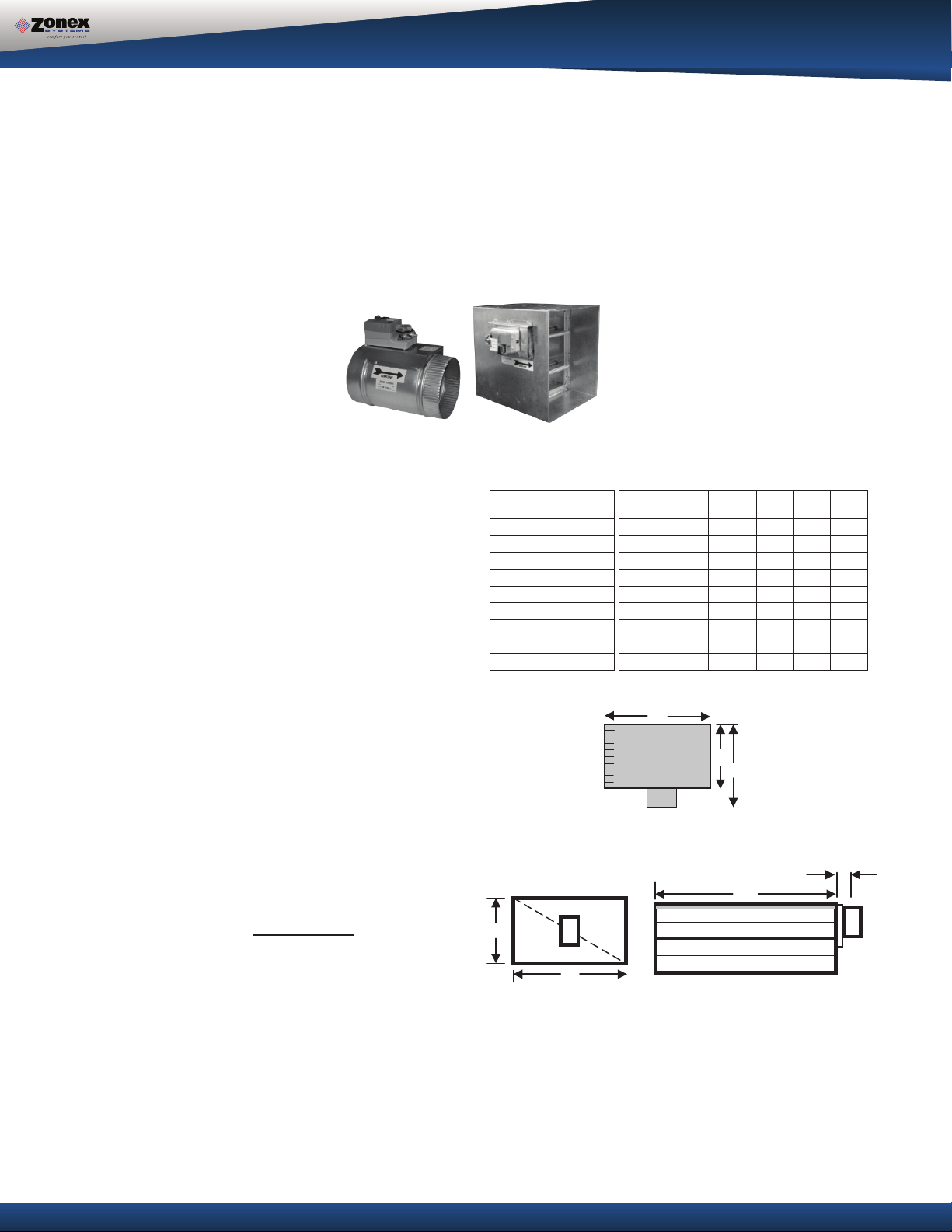
ROUND MEDIUM PRESSURE ZONE DAMPERS
Zonex Systems round medium pressure zone dampers are recommended for systems with a maximum differantial static pressure up to
1.75”. This power open / power closed damper is manufactured from
20-22 gauge galvanized steel with rolled-in stiffening beads for superior
rigidity. Mechanical minimum and maximum set stops are provided and
are easily adjustable. Do not install damper in an inverted position. A
hat section supports a reversing 24vac, 60Hz, 2 VA motor. Motor drive
time from full open to full close is 90 seconds.
3 WIRE ZONE DAMPERS
MAXIMUM
MAXIMUM
ROUND MEDIUM PRESSURE DAMPER
PART NUMBERS AND SIZES
TYPICAL ROUND CAPACITIES
These air qua
ntities were derived from a duct sizing
chart 0.1” friction loss per 100’ of duct. All CFMs
listed are approximate. For accurate selection, use
duct sizing table or device.
PART # SIZE D L W
DUCT
NOMINAL
DUCT VELOCITY
DAMPER
17

D
H
MOTOR
D
2 ½”
48” MAXIMUM WIDTH
ZONE DAMPERS
RECTANGULAR ZONE DAMPERS
The rectangular zone dampers are available in either low pressure or heavy duty. For systems under 5 tons,
use low pressure dampers. For systems 5 tons or over, use heavy duty dampers. Motor drive time open
and close is 90 seconds.
HEAVY DUTY RECTANGULAR DIMENSIONAL DATA
Part Number STCRX W x H
Sizes available from 8” x 8” up to 48” x 48”
RECTANGULAR HEAVY DUTY ZONE DAMPERS (STCRX)
Zonex Systems rectangular heavy duty dampers are recommended for systems 5 tons
or larger with a maximum differential static psure of 1.75”. These are power open /
power closed dampers made of 20 gauge “snaplock” steel frame with S & Drive duct
connections. Allow a 16” gap in the duct for the damper. A full stall motor, drawing 2 VA,
drives the motor from full open to full close in 90 seconds.
Rectangular Damper Capacities*
8 10 12 14 16 18 20 22 24 26 28 30 32 34 36 38 40 42 44 46 48
8
300 400 500 610 710 820 925 1050 1175 1250 1400 1500 1600 1725 1825 2000 2100 2200 2275 2400 2525
10
400 540 680 825 975 1125 1300 1400 1590 1750 1975 2 100 2175 2400 2600 2775 2900 3000 3200 3400 3600
12
500 680 850 1000 1200 1400 1600 1850 2000 2300 2550 2700 2850 3100 3400 3600 3800 3975 4200 4450 5775
14
610 825 1000 1250 1500 1750 2000 2250 2500 2900 3150 3425 3625 3825 4200 4600 4800 5000 5300 5750 6000
16
710 975 1200 1500 1800 2100 2450 2700 3000 3600 3950 4200 4425 4650 5100 5600 5780 6025 6500 7000 7400
18
820 1125 1400 1750 2100 2500 2850 3080 3600 4400 4600 4950 5100 5600 6000 6500 7000 7150 7600 8100 8600
20
925 1300 1600 2000 2450 2850 3400 3775 4000 4800 5500 5700 6000 6600 7100 7900 8025 8500 9000 9600 100 75
22
1050 1400 1850 2250 2700 3080 3775 4300 4800 5100 6000 6350 6800 7200 7800 8600 9000 9600 10000 11500 12500
24
1175 1590 2000 2500 3000 3600 4000 4800 5400 6100 7000 7150 7600 8600 9100 10000 10700 11500 12000 13050 14700
26
1250 1750 2300 2900 3600 4400 4800 5100 6100 6700 7800 8400 8900 10000 10900 11075 12050 13000 14000 15000 15900
28
1400 1975 2550 3150 3950 4600 5500 6000 7000 7800 8400 9150 10000 10700 11900 13000 13800 14900 15200 16500 17500
30
1500 2100 2700 3425 4200 4950 5700 6350 7150 8400 9150 10000 11000 11800 12400 13800 14200 15000 16000 17400 18500
32
1600 2175 2850 3625 4425 5100 6000 6800 7600 8900 10000 11000 11250 12700 13900 14900 15200 16900 1730 0 19000 20500
HEIGHT IN INCHES
34
1725 2400 3100 3825 4650 5600 6600 7200 8600 10000 10700 11800 12700 14100 15000 16500 17200 18100 19200 20500 21900
36
1825 2600 3400 4200 5100 6000 7100 7800 9100 10900 11900 12400 13900 15000 16100 17400 18500 20000 21500 22900 24200
38
2000 2775 3600 4600 5600 6500 7900 8600 10000 11075 13000 13800 14900 16500 17400 17800 20000 21900 22600 24000 25100
40
2100 2900 3800 4800 5780 7000 8025 9000 10700 12050 13800 14200 15200 17200 18500 20000 21000 22200 24900 25000 27000
42
2200 3000 3975 5000 6025 7150 8500 9600 11500 13000 14900 15000 16900 18100 20000 21900 22200 22800 25100 26900 30000
44
2275 3200 4200 5300 6500 7600 9000 10000 12000 1400 0 15200 16000 17300 19200 21500 22600 24900 25100 26500 30000 32000
46
2400 3400 4450 5750 7000 8100 9600 11500 13050 1500 0 16500 17400 19000 20500 22900 24000 25000 26900 30000 30500 32800
48
2525 3600 5775 6000 7400 8600 1075 12500 14700 1590 0 17500 18500 20500 21900 24200 25100 27000 30000 32000 32800 35600
WIDTH IN INCHES
* These air quantities were derived from duct sizing chart .1" friction loss per 100' of duct. All CF .etamixorppa era detsil sM
For accurate selection use duct sizing table or
18

DAMPER TRANSFORMER SIZING
DAMPER TRANSFORMER SIZING
The 24V transformer connected to TR1 and TR2 of the GEN II-R System Controller powers the zone dampers. The power
rating of the transformer must be sufficient to power the number of dampers used. Also, a properly rated in line fuse must be
used on the secondary of the transformer. To determine the power rating of the transformer and the amperage rating of the
fuse, use the table below. If using a combination of spring open and power open dampers, size as if all dampers are spring
open.
TRANSFORMER/FUSE SIZING
NUMBER
OF
DAMPERS
1 40 VA 1 AMP 40 VA 1 AMP
2 40 VA 2 AMP 40 VA 1 AMP
3 40 VA 2 AMP 40 VA 1 AMP
4 40 VA 3 AMP 40 VA 2 AMP
5 48 VA 3 AMP 40 VA 2 AMP
6 60 VA 4 AMP 40 VA 2 AMP
7 72 VA 5 AMP 40 VA 3 AMP
8 84 VA 5 AMP 40 VA 3 AMP
9 96 VA 6 AMP 40 VA 3 AMP
10 108 VA 6 AMP 40 VA 3 AMP
11 120 VA 7 AMP 40 VA 4 AMP
12 132 VA 7 AMP 40 VA 4 AMP
Notice:
All wiring must meet state and local codes.
TR SERIES (12va)
(SPRING OPEN) DAMPERS
XFMR PWR
FUSE SIZE
MED. PRESSURE/HEAVY DUTY(2va)
(POWER OPEN) DAMPERS
XFMR PWR
FUSE SIZE
SLAVING ZONE DAMPERS
SLAVING UP TO THREE 2-WIRE ZONE DAMPERS
Up to three dampers can be directly controlled by one zone damper control board. To wire two or three dampers for a zone,
use the following wiring diagram. Remember to size the power transformer for the total number of zone dampers in the system,
12va per damper.
RUN CLOSED
ZN6
ZN7
RUN OPEN
ZN8
MC
RO
RC
B
A
B
HP
A
ZN9
ZN10
M
ZONE DAMPER 2
TR or TREC damper
M
M
ZONE DAMPER 3
TR or TREC damper
M
R
C
R
C
W/OB
Y
E
ZN1
ZN2
ZN3
ZN4
ZN5
TRX or TREX damper
19

SLAVING ZONE DAMPERS
SLAVING MORE THAN THREE 2-WIRE ZONE DAMPERS
When slaving more than three zone dampers, use the following diagram. An additional 24-volt transformer and control relays are
needed for these applications. Note: All slave dampers need to be model TR / TREC and are 12va per damper.
M
R
C
R
C
W/OB
Y
E
M
M
ZONE DAMPER 1
CONTROL
RELAY
MC
RUN OPEN
RO
RUN CLOSED
RC
B
A
B
HP
ZN1
ZN2
ZN3
ZN4
ZN5
ZN6
A
ZN7
ZN8
ZN9
ZN10
SPST
TR or TREC damper TR or TREC damper
24 VOLT
TRANSFORMER
M
ZONE DAMPER 2
M
M
ZONE DAMPER 3
TR or TREC damper
TRX or TREX damper
SLAVING UP TO THREE ST SERIES 3-WIRE ZONE DAMPERS
Up to three dampers can be directly controlled by one zone damper control board. To wire two or three dampers for a zone,
use the following wiring diagram. Remember to size the power transformer for the total number of zone dampers in the system,
2va per damper.
ACTUATOR
RC
RO
MC
RUN CLOSED
ZN6
RUN OPEN
ZN7
MC
RO
RC
B
A
B
HP
A
ZN8
ZN9
ZN10
RC
ZONE DAMPER 2
STMPD or STCD damper
MCRO
STMPD or STCD damper
RC
ZONE DAMPER 3
MCRO
R
C
R
C
W/OB
Y
E
ZN1
STMRX or STCRX damper
ZN2
ZN3
ZN4
ZN5
SLAVING MORE THAN THREE ST SERIES 3-WIRE ZONE DAMPERS
When slaving more than three zone dampers, use the following diagram. An additional 24-volt transformer and control relays are
needed for these applications. Note: All slave dampers need to be model STMPD / STCD
ACTUATOR
RC
R
C
R
C
W/OB
Y
E
ZN1
STMRX or STCRX damper
RC
RO
RC
RO
MC
MC
RUN OPEN
RO
RUN CLOSED
RC
B
A
B
HP
ZN2
ZN3
ZN4
ZN5
ZN6
A
ZN7
ZN8
ZN9
ZN10
CONTROL
RELAY
SPST
CONTROL
RELAY
SPST
MC
ZONE DAMPER 1
STMPD or STCD damper STMPD or STCD damper
24 VOLT
TRANSFORMER
MC
ZONE DAMPER 2
RC
RO
MC RO
ZONE DAMPER 3
STMPD or STCD damper
20

BYPASS DAMPERS
Bypass dampers are used to provide constant air delivery
through the air handling unit. This is done by bypassing excess
air from the supply duct back to the return duct. As a zone is
satisfied, its zone damper closes. When this happens, the
bypass damper opens just enough to bypass the excess air.
This will control static pressure and noise at the diffusers.
Zonex Systems offers two types of bypass dampers, Barome-
BYPASS DAMPERS – BAROMETRIC
The barometric bypass damper is for systems 5 tons or under.
It utilizes a weighted damper blade to maintain constant duct
pressure. This allows for easy installation without the need for
electrical power or wiring. The round barometric damper can
be installed in any position. The RBB rectangular damper must
be installed with horizontal air flow only.
SIZING: When only the smallest zone is calling, the maximum
amount of excess supply air flow through the bypass damper.
To determine the proper size bypass damper to use, do the
following steps:
Step 1: Calculate bypass air volume as
follows:
A) Calculate total air volume at 400
CFM per ton.
B) Calculate air volume of smallest
zone in CFM.
C) Calculate bypass air volume by
subtracting the smallest zone air
volume from the total. (A - B = C)
BAROMETRIC BYPASS
SELECTION TABLE
Diameter CFM
9” 650
10” 800
12” 1200
14” 1600
16” 2000
BYPASS DAMPERS
tric and electronic. Each is available in round or rectangular
configuration. Barometric bypass dampers are limited to
systems of 5 tons. Electronic bypass dampers can be used on
any size system. For residential HVAC systems with variable
speed blowers, the barometric or electric bypass dampers can
be used. NOTE: When using the electronic bypass (STBP/ST-
CDBP), see the Bypass Dampers - Electronic Section, Pages
23-26; or contact Technical Support at 800-228-2966.
If bypassing more than 2000 CFM, use the electronic bypass.
Example: You have a 4 ton system. Your smallest zone will use
500 CFM. The total CFM is 1600 CFM (400*4). Your bypass
CFM is 1100 (1600-500). From the table, you determine that a
12” bypass damper is needed.
Do not use the barometric bypass in any system over 5 tons,
for systems over 5 tons, or to bypass more than 2000 CFM,
use the electronic bypass.
BAROMETRIC BYPASS
DAMPER
AIRFLOW
3
4
RECTANGULAR & ROUND
BAROMETRIC BYPASS
1
2
1. Damper Shaft
2. Lock Nut
3. Lever Arm
4. Counter Weight
Step 2: Select damper from sizing table. Once you have calcu-
lated the bypass air volume from Step 1, use the
BAROMET-
RIC BYPASS SELECTION TABLE. From the table, select the
bypass damper with CFM rating equal to or greater than the
value calculated in Step 1. For rectangular barometric dampers,
use a ductulator to convert from round to rectangular.
21

BYPASS DAMPERS- BAROMETRIC
INSTALLATION
The round barometric bypass damper can be installed in any
position. This damper is factory set for horizontal installation
and can be field modified for vertical installation. Do not run
speed screws into damper housing. Screws may interfere with
damper travel. Make sure counterweight is not obstructed in any
way.
a) Install the bypass damper between the supply and return
plenums of the unit. It must be the first tap off the supply plenum.
b) Be sure the air flows through the damper in the proper
direction as indicated by the arrow on the damper. Airflow
is always from supply to return plenum. Be certain the
damper shaft is horizontal.
c) Loosen counter weight with allen wrench.
d) Loosen lever arm from damper shaft and allow to hang
straight down.
e) Fully close damper by grabbing damper shaft on side
attached to lever arm and turning clockwise until it stops.
f) While holding the damper fully closed, rotate the lever
arm a little to the right (facing the damper) and then
screw into tighten to the damper shaft. Then tighten lock
nut.
BAROMETRIC BYPASS SETUP
a) Turn off all thermostats.
b
) Turn on Controller and set fan switch to “ON” position.
Allow fan to run for 5 minutes to equalize pressure.
Then make sure all dampers are open by checking
for air flow out of each damper.
c) By moving counter weight up or down the lever arm,
adjust it so the damper just wants to start opening.
d) If the damper cannot be held closed with the counter
weight all the way to the bottom of the lever arm, then
hold the damper shaft, loosen the lever arm from the
damper shaft, and rotate the lever arm farther to the
right and retighten. Repeat Step C.
e) The barometric bypass damper is now calibrated.
BAROMETRIC BYPASS STARTUP TEST
a) Have at least half of the zones call for either heating or
cooling.
b) Check to be sure the calling zone dampers are open,
(air is flowing).
c) Verify the bypass damper is open. Note, the damper
may not fully open.
g) Be sure the damper is being held closed by the counter
weight. Proceed to setup.
HORIZONTAL APPLICATION
AIRFLOW
SHEET METAL
PIPE
AIRFLOW
BAROMETRIC
BYPASS
RETURN
VERTICAL APPLICATION
A/C UNIT
OR
FURNACE
BAROMETRIC
BYPASS
SUPPLY
PLENUM
A/C UNIT
OR
FURNACE
RETURN AIR GRILLE
RETURN
AIR
PLATFORM
SUPPLY
PLENUM
AIRFLOW
OPEN RETURN PLENUM BYPASS APPLICATION
To prevent bypass air from
flowing out the return grill,
use a short open ended
return air plenum to
connect the bypass
damper to the unit.
RETURN AIR
d) If the open zones are not noisy, the bypass damper is
set.
ROOFTOP INSTALLATION Down Discharge Application
A/C UNIT
OR
FURNACE
BAROMETRIC
BYPASS
PIPE
AIRFLOW
UNIT
SUPPLY
DUCT
GRILLE
SUPPLY
PLENUM
SHEET METAL
BYPASS DAMPER
AIR CONDITIONING
ROOF LINE
RETURN
PLENUM
22
8”
560
10”
900
12”
1250
14”
1700
16”
2200
18”
2600
20”
3300
22”
4000
24”
4700
STBP08
88”10”
11”
STBP10
10
10”
12”
13”
STBP12
12
12”
14”
15”
STBP14
14
14”
16”
17”
STBP16
16
16”
18”
19”
STBP18
18
18”
23”
21”
STRDBP20
20
20”
24”
27”
STRDBP22
22
22”
24”
27”
STRDBP24
24
24”
24”
27”
ROUND BYPASS SELECTION TABLE
4”
H
D
W
48” MAXIMUM WIDTH
RECTANGULAR BYPASS DAMPERS
D
L
W
BYPASS DAMPERS- ELECTRONIC
ELECTRONIC BYPASS DAMPERS
Bypass dampers are used to provide constant air delivery through the air handling unit. This is done by
bypassing excess air from the supply duct back to the return duct. As a zone is satisfied, its zone damper
closes. When this happens, the bypass damper opens just enough to bypass the excess air. This will control
static pressure and noise at the diffusers.
The Electronic Bypass Damper is used on any size system over 5 tons.
The damper can be round (STBP) or
rectangular (STCDBP) with integrated static pressure control; and multiple dampers can be slaved together.
SIZING ELECTRONIC BYPASS DAMPERS
The bypass damper is to be sized for the total
system CFM @ 1500 FPM. System CFM should
Diameter CFM
PART # SIZE D L W
be calculated at 400 CFM per ton.
Example: A 5-ton system is rated at 2000 CFM
(5x400 = 2000). When calculated at 1500 FPM,
the bypass damper should be 16”. Never
undersize the bypass damper.
ROUND BYPASS DAMPER SE
LECTION
The Zonex Systems STBP damper is used for
round bypass applications. When you know the
bypass CFM requirements, use the ROUND
BYPASS SELECTION TABLE to confirm the
round damper size.
NOTE: Multiple round dampers can be slaved
from one static pressure control to provide the
correct capacity. One large rectangular bypass
damper may be used instead of multiple round
dampers. See below.
RECTANGULAR BYPASS DAMPER
SELECTION
The Zonex Systems STCDBP WxH
used for rectangular bypass applications. These
dampers are also sized for the total system CFM
rated at 1500 FPM. Multiple dampers can be
slaved from a single static pressure control.
damper is
SELECT FROM 8 x 8 thru 48 x 48
23

WIDTH IN INCHES
81012141618202224283236404448
8
667
833
1000
1167
1333
1500
1667
1833
2000
2333
2667
3000
3333
3667
4000
10
833
1042
1250
1458
1667
1875
2083
2292
2500
2917
3333
3750
4167
4583
5000
12
1000
1250
1500
1750
2000
2250
2500
2750
3000
3500
4000
4500
5000
5500
6000
14
1167
1458
1750
2042
2333
2625
2917
3208
3500
4083
4667
5250
5833
6417
7000
16
1333
1667
2000
2333
2667
3000
3333
3667
4000
4667
5333
6000
6667
7333
8000
18
1500
1875
2250
2625
3000
3375
3750
4125
4500
5250
6000
6750
7500
8250
9000
20
1667
2083
2500
2917
3333
3750
4167
4583
5000
5833
6667
7500
8333
9167
10000
22
1833
2292
2750
3208
3667
4125
4583
5042
5500
6417
7333
8250
9167
10083
11000
24
2000
2500
3000
3500
4000
4500
5000
5500
6000
7000
8000
9000
10000
11000
12000
28
2333
2917
3500
4083
4667
5250
5833
6417
7000
8167
9333
10500
11667
12833
14000
32
2667
3333
4000
4667
5333
6000
6667
7333
8000
9333
10667
12000
13333
14667
16000
36
3000
3750
4500
5250
6000
6750
7500
8250
9000
10500
12000
13500
15000
16500
18000
40
3333
4167
5000
5833
6667
7500
8333
9167
10000
11667
13333
15000
16667
18333
20000
44
3667
4583
5500
6417
7333
8250
9167
10083
11000
12833
14667
16500
18333
20167
22000
48
4000
5000
6000
7000
8000
9000
10000
11000
12000
14000
16000
18000
20000
22000
24000
HEIGHT IN INCHES
DAMPER
SLAVE
TO NEXT SLAVE
B
I
RC
R
M
RECTANGULAR BYPASS SELECTION TABLE
RECTANGULAR BYPASS SELECTION TABLE
Bypass air in CFM. Calculated at 1500 FPM.
Formula used: B = W x H / 144 x 1500, where B = Bypass air in CFM, W = damper width in inches, H = damper height in inches,
144 = 144 sq. inches per sq. ft., 1500 = 1500 FPM.
ROUND AND RECTANGULAR
BYPASS DAMPER MOTORS
SLAVING BYPASS DAMPERS
Use only one Pressure Sensor when slaving two or more
Bypass Dampers together. Connect the Pressure Sensor
to one damper as described above. Connect the slave
dampers in parallel as shown. Up to 4 dampers can be
slaved to one Sensor. The slaved dampers will selfsynchronize each time the dampers reach full open or full
close.
ACTUATOR
RC RO MC RC RO MC
To Static Pressure Control, as shown on the Bypass
Wiring Diagram on the next page.
DAMPER
ACTUATOR
YPASS DAMPER
F APPLICABLE
O
C
24

INTEGRATED PRESSURE CONTROL SETUP
BYPASS DAMPER with INTEGRATED PRESSURE CONTROL
(Part # STBP or STCDBP)
Bypass Damper with Integrated Pressure Control is used to control bypass operations. The bypass damper
modulates to maintain static pressure as zone dampers open and close. The bypass system reduces air noise
from the supply registers caused by excessive air velocity. If the system is configured for intermittent fan mode and
the system satisfies, there will be a 3-minute delay to allow for system purge, after which the bypass damper will
open to
the system is configured for fan continuous operation, the STBP (Round) or STCDBP (Rectangular) Electronic
Bypass will monitor static pressure continuously, providing constant control of system static.
25%, preventing noisy rush of air through supply registers when fan starts up on a call for heat or cool. If
INTEGRATED PRESSURE CONTROL
DESCRIPTION
A. Supply air tube
B. 24vac R and C
C. Damper Terminal RO, RC, MC
D. LED lights
E. Adjustable Potentiometer
F. TP1 Test Point
Fig. 1
BYPASS DAMPER INSTALLATION
5. Drill ¼” hole into the side of the supply duct 2’
after the bypass and before the 1
st
supply takeoff. Mount pressure supporting block over ¼”
hole, align hole in block with hole in duct. Use
provided sheet metal screws.
6. Install air tube into supp
ly air duct by slipping
supplied plastic tubing into holes in support block
and duct. Slip tube 3” into the duct. Pickup
tubing fits snugly into provided hole.
7. Connect pressure tube from static air pickup to
Integrated Pressure Controller (port closest to
you).
Fig. 2
BYPASS DAMPER WITH INTEGRATED BYPASS
CONTROL SETUP
1. Verify the bypass damper is sized properly to the
system and not undersized. (Bypass damper
sizing is recommended for 100% of system CFM.)
2. Bypass damper and controller are powered by a
dedicated 24vac 40VA transformer.
3. Do not install the bypass damper outside.
4. Locate the Integrated Pressure Control (IPC) and
air tube on the bypass damper.
1. Run all supply dampers to the full open position
and have blower motor running at 100% fan
speed. (See Note #1)
2. Manually close the bypass damper by pressing
in the release lever on the motor side of the
actuator. With the re
lease lever pressed, rotate
the damper actuator collar to close the damper
and release the lever to lock the damper closed.
3. Quick Set Option: Turn the potentiometer on
the damper control board to the full left position
and slowly rotate RIGHT, until the “RC” RED
LED turns on. Now rotate LEFT just slightly, until
RC LED turns off. The IPC is ready for
operation.
“RC” RED LED means damper closing.
“RO” GREEN LED means damper opening.
25

INTEGRATED PRESSURE CONTROL SETUP
4. Static Pressure Option: The Integrated Pressure
Control Board can be field configured for specified
static pressure using a multi meter and the static
pressure – voltage chart. (Exhibit A). This chart
shows voltage (DC) to inches of W.C. (static
pressure) relationship. Use a multi meter set on
VDC and place the leads on the “C” terminal and
“TP1” (test point one) next to the potentiometer.
The Voltage reading translates to inches of W.C.
BYPASS CHECKOUT FOR STATIC PRESSURE
CONTROLLER
1. Make cool call at the zone thermostat of the
smallest zone.
2. Verify all zone dampers are closed except for
calling zone.
3. Verify noise at zone registers is not excessive.
Adjust the Integrated Pressure Control LEFT to
lower noise (airflow) or RIGHT to increase airflow
until too noisy.
BYPASS DA
WITH INTEGRATED BYPASS CONTROL
MPER WIRING DIAGRAM
Note # 1: To open all dampers, it may be necessary
to remove Y outputs to unit on the zone control board
and to make full cool calls on all thermostats. This will
modulate dampers fully open and lock out compressor.
26

Quick Quote Web Site:
GEN II-R
Hot Line: (800) 228-2966
5622 Engineer Drive
Huntington Beach, CA 92649
Factory: (714) 898-9963
Fax: (714) 898-6802
Visit our Web Site http://www.zonexproducts.com
www.zonexproducts.com
The easy way to Get Quotes Fast
Zonex Systems reserves the right to discontinue,
or change at any time, specifications or designs
without notice and without incurring obligations.
Copyright 2018 by Zonex Systems
Part #GENII-RMAN PATENTED PRODUCT
December 2018
 Loading...