


T
ABLE OF CONTENTS
English………………………………………………………………………………1
Package Contents………………………………………………………………………1
Application……………………………………………………………………………………1
Front Panel…………………………………………………………………………………………2
Rare Panel…………………………………………………………………………………………2
Side Panel…………………………………………………………………………………………2
Desktop Installation…………………………………………………………………………3
Rack Installation…………………………………………………………………………………4
Hardware Installation…………………………………………………………………5
Caution………………………………………………………………………………………………6
Troubleshooting…………………………………………………………………………………7
Español…………………………………………………………
……
……………………8
Contenido de Paquete………………………………………………………………………8
Aplicación……………………………………………………………………………………………8
Panel
Panel
Panel
Frontal
Posterior
Lateral
………………………………………………………………………………………9
…………………………………………………………………………………9
………………………………………………………………………………………9
Instalación en Escritorio…………………………………………………………………10
Instalación en Rack…………………………………………………………………………11
Instalación del Hardware…………………………………………………………………12
Precaución………………………………………………………………………………………13
Resolución de Problemas…………………………………………………………………14
1
PPaacckkaaggee CCoonntteennttss
One ZFS3416E/ZFS3424E
One Quick Installation Guide
One Power Cord
One R
Four Rubber Pads
Contact your local authorized reseller or the store purchased from for
any items damaged and/or missing.
ackmount Kit
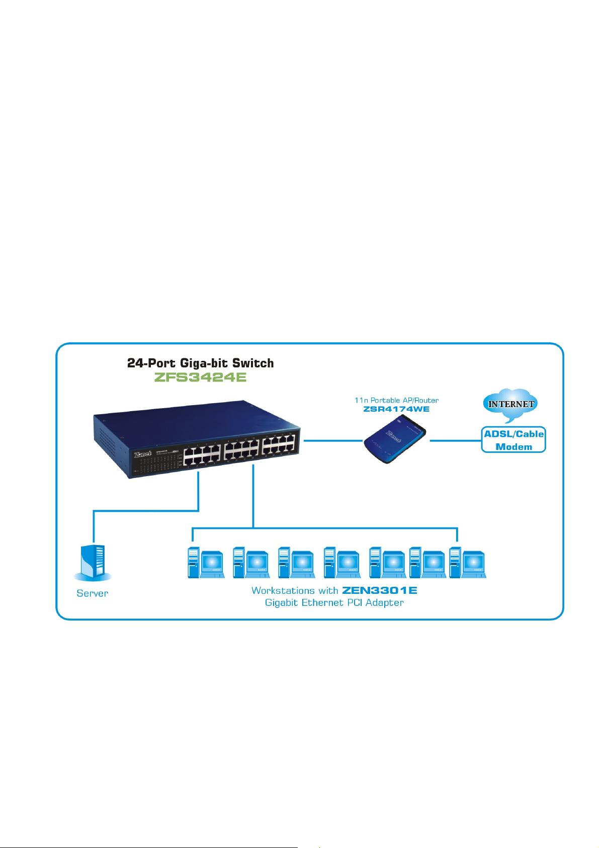
AApppplliiccaattiioonn
2
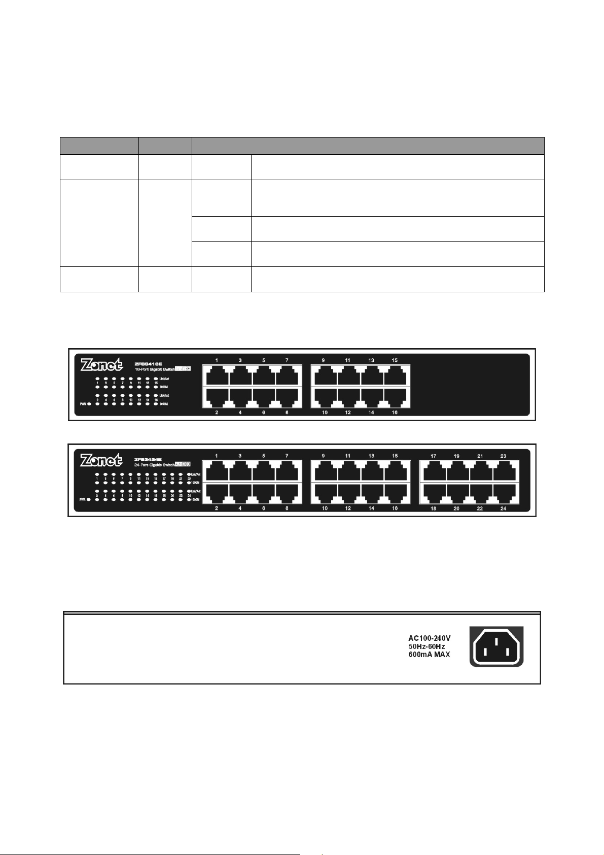
FFrroonntt PPaanneell
Network cable connected and connection
LED indicators
LED Status Operation
POWER Green Steady Power is ON
Link/Act Green
1000Mbps Green
Diagram
a. ZFS3416E
b. ZFS3424E
Steady
established
Flash Data packets are transmitting
Off Network cable is unplug
Steady A 1000Mbps device is connected
RReeaarr PPaanneell
One Power Connector
SSiiddee PPaanneell
Ventilation/cooling holes and mounting holes
3
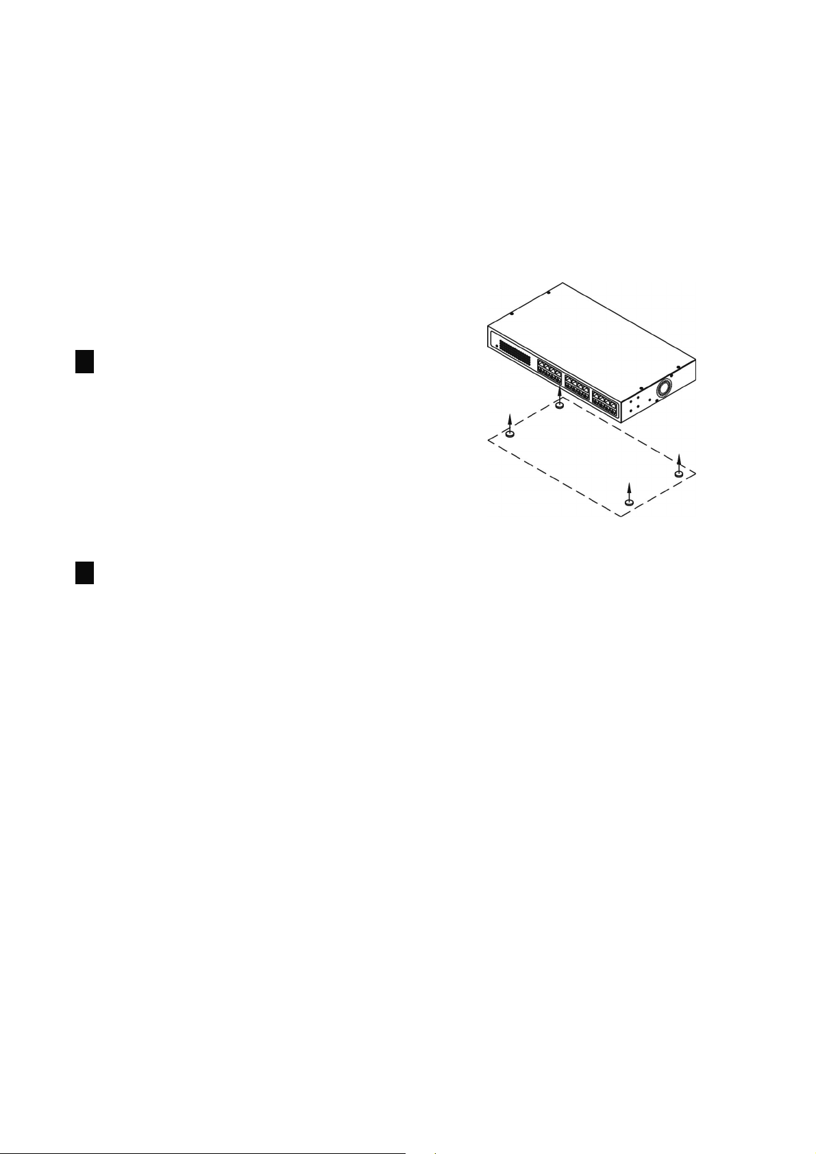
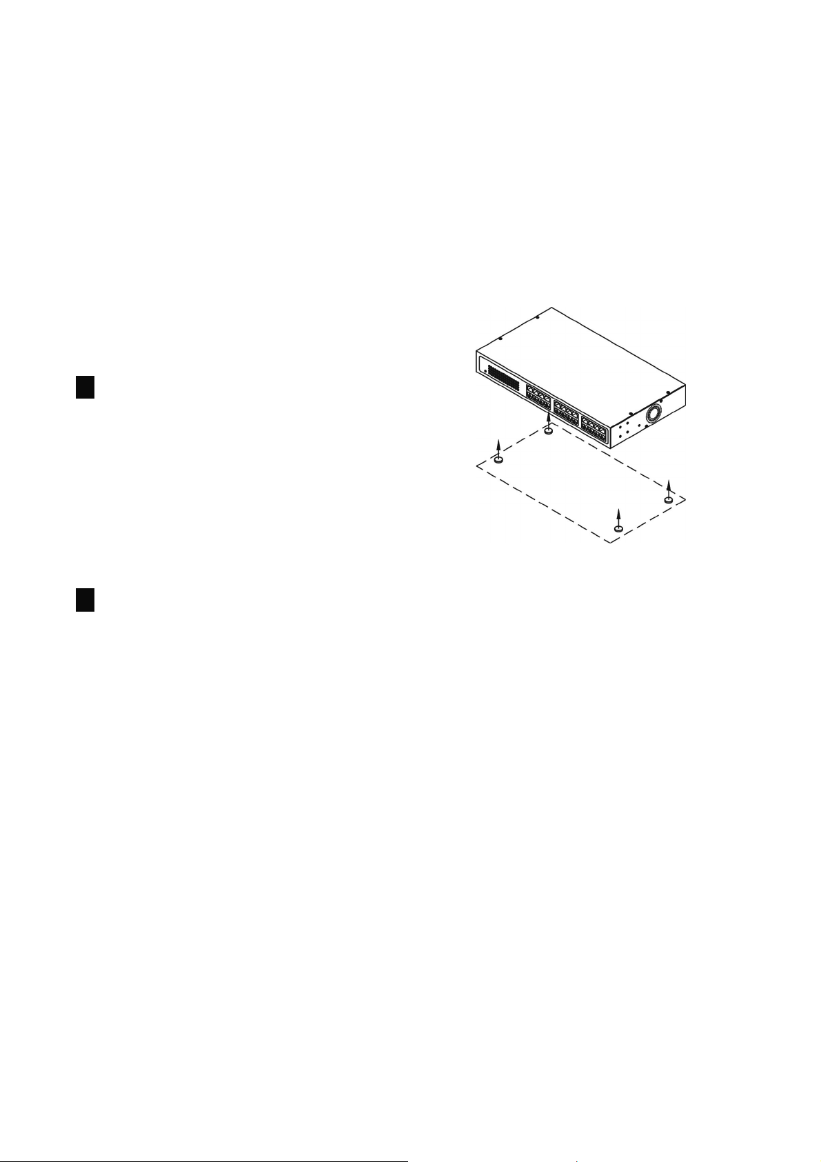
DDeesskkttoopp IInnssttaallllaattiioonn
When placing ZFS3416E/ZFS3424E on a desk-top or shelf, the rubber
pads applied must be first attached to avoid surface damage.
1. Attach applied cushioning rubber
pads on the bottom at each corner
of ZFS3416E/ZFS3424E.
2. Allow enough empty space around
ZFS3416E/ZFS3424E for sufficient
ventilation and cooling.
4
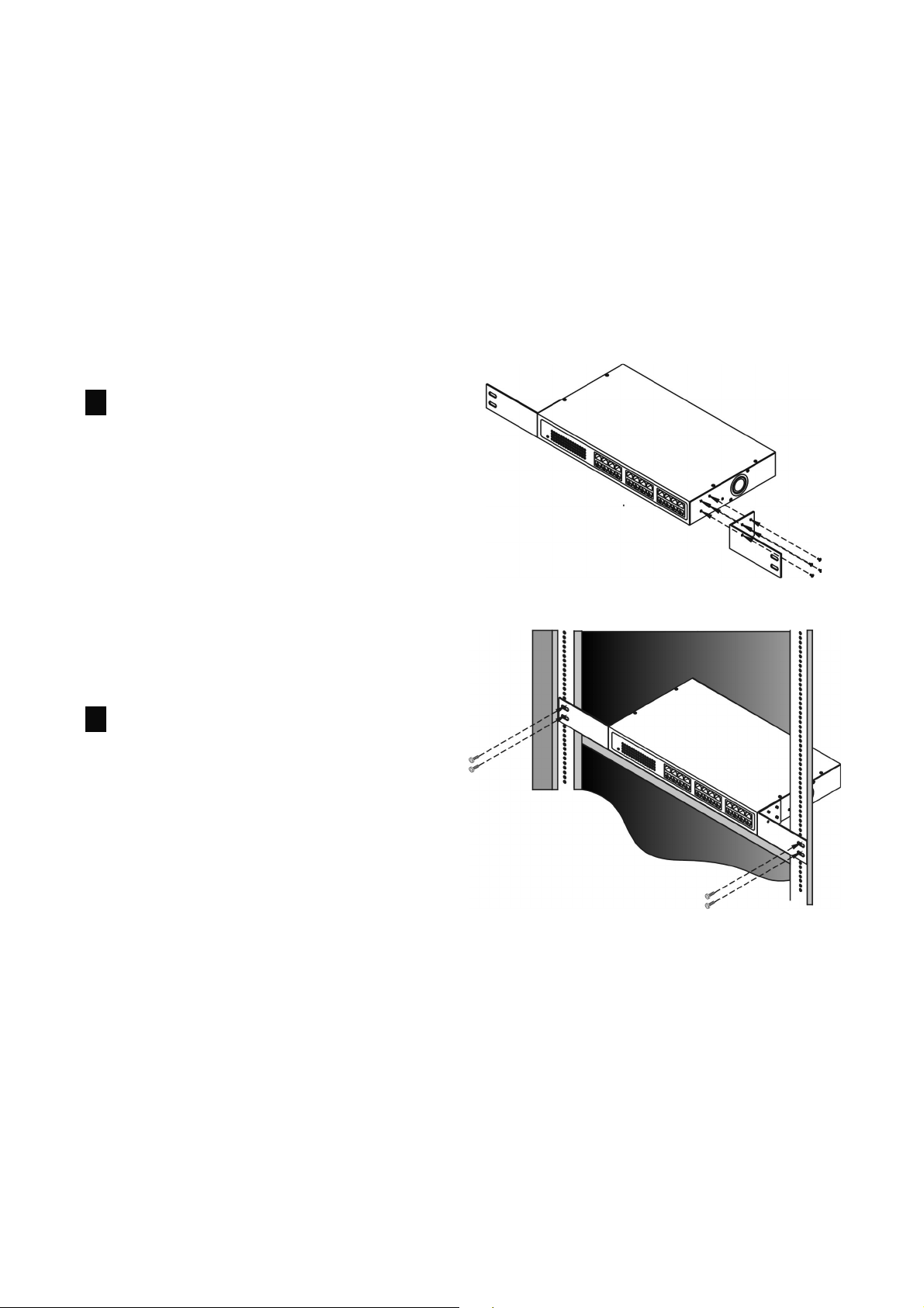
RRaacckk IInnssttaallllaattiioonn
ZFS3416E/ZFS3424E can be mounted in a standard 19-inch rack for
placing in a wiring closet with other equipment. For placing in the rack,
the mounting kit applied must be first attached to the
ZFS3416E/ZFS3424E.
1. ZFS3416E/ZFS3424E has four
mounting holes on each side.
Attach applied mounting
brackets one on each side. Then
secure the bracket with screws
provided.
2. Place ZFS3416E/ZFS3424E in
the rack and secure the
brackets with screws provided
with equipment rack.

5
HHaarrddwwaarree IInnssttaallllaattiioonn
1. Power off all the devices you will
connect to the
ZFS3416E/ZFS3424E.
2. Connect the power cord to the
wall socket, and then connect it
to “Power” socket of
ZFS3416E/ZFS3424E.
3. Connect all your computers,
network devices
(network-enabled consumer
devices other than computers,
like game console, or switch /
hub) to the LAN port of
ZFS3416E/ZFS3424E with
UTP/STP Category 3/4/5
cables.
4. Power on the devices connected
to ZFS3416E/ZFS3424E. LED of
each active port will light up on
ZFS3416E/ZFS3424E.

6
CCaauuttiioonn
•
ZFS3416E/ZFS3424E must put on a surface that is able to hold at
least 5kgs weight
•
Power line must be connected to the switch properly and securely
•
Suggested at least 10cm empty space around the unit for sufficient
ventilation and cooling
•
Do not recommend to put any items on top of the switch
•
ZFS3416E/ZFS3424E is not ideally to work in a high
electromagnetic environment, under direct sunlight, dust and
vibrating surfaces
•
Maximum distance between the switch and the end node is 100
meters
•
Must use an unshielded or shielded twisted-pair (UTP/STP)
Category 5 or better cables to ensure proper transmission
•
Loss of data packet may encounter when using cable other than
Category 5

7
TTrroouubblleesshhoooottiinngg
1. Check the power cord and power wall-jet to make sure they are
function properly. Check if ZFS3416E/ZFS3424E is turned-ON and
power LED is steady.
2. Check all cable connections between computer and
ZFS3416E/ZFS3424E to make sure they are connected properly.
3. Maximum distance is 100 meters from the switch to end nodes.
4. Link LED(s) is ON/flashing at the connected port(s) of
ZFS3416E/ZFS3424E.
5. Test your computer’s network adapter to make sure it is installed
and functioned properly.
6. Check issues such as network collisions, domain limitations, and
other physical installation aspects. Make sure they all meet IEEE
standard network installation requirements, more details can be
found at www.ieee.org.
7. If problem still persists, write down your software/hardware
configuration and LED error indications and contact your local
retailer or the store purchased for further assistance.

8
CCoonntteenniiddoo ddeell PPaaqquueettee
Uno ZFS3416E/ZFS3424E
Guía de Instalación Rápida
Uno Cordón de Poder
Dos abrazaderas en L para montaje en rack y tornillos
Cuatro
Contacte a su revendedor autorizado en su localidad o a su tienda en
donde lo compro para cualquier aclaración sobre productos dañados o
partes faltantes.
AApplliiccaacciióón
bases de goma
n

9
PPaanneell FFrroonnttaall
Se están transmitiendo paquetes de
bps
Indicadores LED
LED Estado Operación
PODER Verde Estable El switch recibe energía
Link/Act Verde
1000Mbps Verde
Diagramas
a. ZFS3416E
b. ZFS3424E
Estable
El cable de red está conectado y la
conexión establecida
Parpadeando
datos
Apagado El cable de red esta desconectado
Indica que un dispositivo a 1000M
Estable
está conectado
PPaanneell PPoosstteerriioorr
Uno Conector de Poder
PPaanneell LLaatteerraall
Orificios de ventilación y orificios para montaje
10
IInnssttaallaacciióónn eenn EEssccrriittoorriioo
Cuando coloque el ZFS3416E/ZFS3424E sobre un escritorio o estante,
deberá de colocar primero las bases de goma para impedir que la
superficie se maltrate.
1. Coloque y pegue las bases de
goma en cada una de las
esquinas inferiores del
ZFS3416E/ZFS3424E.
2. Permita suficiente espacio libre
alrededor del
ZFS3416E/ZFS3424E para una
adecuada ventilación y
enfriamiento.

11
IInnssttaallaacciióónn eenn RRaacckk
El ZFS3416E/ZFS3424E puede ser montado en un rack estandar de 19
pulgadas para colocarlo en un gabinete de cableado junto a otro
equipamiento. Para montarlo en el rack, primero devera de colocar los
kits para montaje a los costados del ZFS3416E/ZFS3424E.
1. El ZFS3416E/ZFS3424E tiene
cuatro orificios para montaje en
cada costado. Fije los herrajes
de montaje en cada costado.
Después asegúrelos con los
tornillos proporcionados.
2. Coloque el ZFS3416E/ZFS3424E
en el rack y fije el herraje con los
tornillos proporcionados con el
equipo de rack.

12
Instalacióónn del Hardware
I
1. Apague todos los dispositivos
que conectara al
ZFS3416E/ZFS3424E.
2. Conecte el cable de poder al
contacto en la pared, y después
conéctelo al “enchufe de
poder“ del
ZFS3416E/ZFS3424E.
3. Conecte sus dispositivos de red a
los puertos RJ-45 del
ZFS3416E/ZFS3424E con cable
UTP/STP Categoria 3/4/5.
4. Encienda los dispositivos
conectados al
ZFS3416E/ZFS3424E. El
correspondiente indicador LED
de cada puerto activo encenderá
en el panel del
ZFS3416E/ZFS3424E.

13
PPrreeccaauucciióónn
•
El ZFS3416E/ZFS3424E se debe de colocar en una superficie que
pueda soportar por lo menos un peso de 5kgs
•
El adaptador de poder se debe conectar con el switch de manera
correcta y con firmeza
•
Deje por lo menos un espacio vacío sugerido de 10cm alrededor
de la unidad para una ventilación y enfriamiento adecuado
•
No permita que coloquen ningún artículos encima del switch
•
El ZFS3416E/ZFS3424E no está diseñado para trabajar en un
ambiente con elevado electromagnetismo, bajo la luz directa del
sol, superficies con vibración o mucho polvo
•
La distancia máxima entre el switch y el nodo final es 100 metros
•
Debe utilizar cable par retorcido sin blindaje o blindado (UTP/STP)
categoría 5 o superior para asegurar la transmisión apropiada
•
La pérdida de paquetes de datos se puede dar al usar cables que
no sean al menos categoría 5

14
RReessoolluucciióónn ddee PPrroobblleemmaass
1. Compruebe el adaptador de poder y la salida del contacto de
pared para cerciorarse de que los dos funcionen correctamente.
Compruebe si el switch está encendido y el LED indicador de poder
esta constante.
2. Compruebe todas las conexiones de cable entre la computadora y
el switch para cerciorarse de que están conectadas correctamente.
3. La distancia máxima entre el switch y los extremos de los nodos es
de 100 metros.
4. El LED de enlace debe de estar encendido/parpadeando para los
puertos que este conectados
5. Pruebe el adaptador de red de su PC para cerciorarse de que está
instalado y funcionado correctamente.
6. Revise los detalles como colisiones de la red, limitaciones del
dominio, y otros aspectos físicos de la instalación. Cerciórese de
cumplir todos los requisitos del estándar IEEE referentes a la
instalación, usted puede encontrar más detalles en www.ieee.org.
7. Si todavía persiste el problema, anote su configuración de
software/hardware y el estado de los indicadores LED y póngase
en contacto con su revendedor o la tienda en donde compra la
unidad para asistencia adicional.
 Loading...