


1166//2244 PPoorrttss G
Giiggaabbiitt SS
wiittcchh
w
ZFS3216E/ZFS3224E
Quick Installation Guide
Features
Green
‧
Plug & Play
‧
Complies with IEEE802.3, IEEE802.3u, IEEE802.3ab, IEEE802.3x standards
‧
NWAY Auto-negotiation support, Auto-Sense the transmission speed, half/full duplex
‧
16/24 ports 10/100/1000M Auto-Sense, Auto-MDI/MDIX
‧
Adopt IEEE802.3x flow control for full-duplex and backpressure for half-duplex
‧
Store and forward structure
‧
MAC address auto learning
‧
Support IEEE802.3x for broadcasting storm control
Package Contents
‧
One 16/24 Ports Gigabit Switch
‧
One Quick Installation Guide
‧
One Power Adapter
‧
Four rubber pads
‧
Two L
-shape rackmount brackets and screws
Front Panel
‧
LED lights panel
LED Status Operation
Power Green Steady: Power is ON
10/100M Link Green
Full Duplex
(FDX/COL)
1000M Link/Act
‧
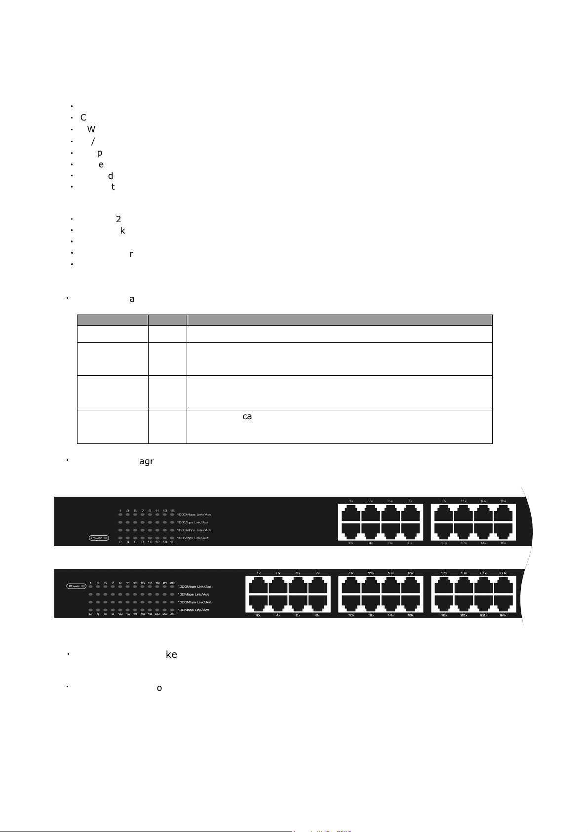
Front Panel Diagrams
ZFS3216E(top) / ZFS3224E(bottom)
Green
Steady: Indicates a 10/100M device is connected
Flash: the port is transmitting/receiving data
Off: Indicates
Steady: Indicates
Flash:
Off: Indicates
Steady: Indicates a Gigabit device is connected
Flash: the port is transmitting/receiving data
Off: Indicates
Indicates there is data collision at this port
either a 10M device or no device connected
this port is working under
this port is working under
either a 10/100M device or no device connected
full duplex mode
half duplex mode
Rear Panel
‧
AC power line socket and power switch
Side Panel
‧
Ventilation and cooling holes
Please make sure there are no substances blocking up these holes, and leave enough space on both sides of
the switch, so the switch can have proper ventilation and cooling to avoid over heat inside the unit, which
may cause damages and/or system malfunctions.

Installation
1. Connect the output power to the AC-inlet of the Switch
2. Connect other IEEE802.3 compatible network device (Hub, Switch, PC) to RJ-45 port of the Switch using
Category 3/4/5 UTP/STP cables.
3. Connect another IEEE802.3 compatible network device (Hub, Switch, PC) to another RJ-45 port of the Switch
by following the same process as described in Step2.
Caution
‧
The switch must put on a surface that is able to withstand at least 5Kgs weight.
‧
The power line should be properly and tightly connect with the switch power socket and power supply socket.
‧
Make sure ventilation and cooling is sufficient for the switch; suggested at least 10cm space in distance
around the unit.
‧
Don’t put any heavy items on top of the switch.
‧
Power supply requirement: 160-240VAC 50/60HZ, grounded connection
‧
Don’t installing the switch at high electromagnetic environment, under direct sunlight, dust and vibrate
surfaces.
‧
Install all four(4) rubber pads at the bottom corners of the switch to avoid scratch at the bottom surface.
‧
When installs it on the rack, make sure to fix tight it on the rack with the screw.
‧
Maximum cable distance between the Switch and other IEEE802.3 compatible network devices is 100 meters
‧
Only Category 3/4/5 cables can be used in 10 Mbps operation mode.
Must use an Unshielded/Shielded Twisted-Pair (UTP/STP) Category 5 cable or higher Grade data cables in
order to operate 100Mbps and 1000Mbps network operations.
May experience loss of data packets when Category 3 or 4 cables are used.
‧
Auto-MDIX ports allow all kinds of IEEE802.3 compatible network devices, such as hub, switch and
computers, to connect to the Switch using straight-through wires and/or crossover cables.
Troubleshooting
We always do our best to deliver high quality products to our customers; however, problems may still occur
when using the product. Many problems are due to disconnected cables, faulty cables, exceeded maximum
cable length, or malfunctioning NIC. Below are some troubleshooting tips you may try when the switch is not
functioning correctly.
1. Check power to see if it functions properly.
Make sure the power switch is turned on and the power LED is on steady. If the Power LED is not ON, check
the power source and power cable.
2.Check connection to see if it is done correctly and properly between computers and switch or between
switches. Make sure all devices are connected to the network properly and the Link LED is ON on connected
ports.
3.Check the NIC to see if it is installed and function properly.
4.Check the cable length to see if it reaches the maximum distance.
5.Check straight-through and/or crossover, cable collision, domain limitation, and other physical installation
aspects to see if they meet standard network installation requirements.
Notice:
If problem still persists and cannot be solved, write down your software/hardware configuration and error
indications from LEDs and call your local retailer or the store purchased for further assistance.
 Loading...