

ZONDA HOBBY TECHNOLOGIES ELECTRONIC HK0001 User Manual
GWY004539 6T Transmitter
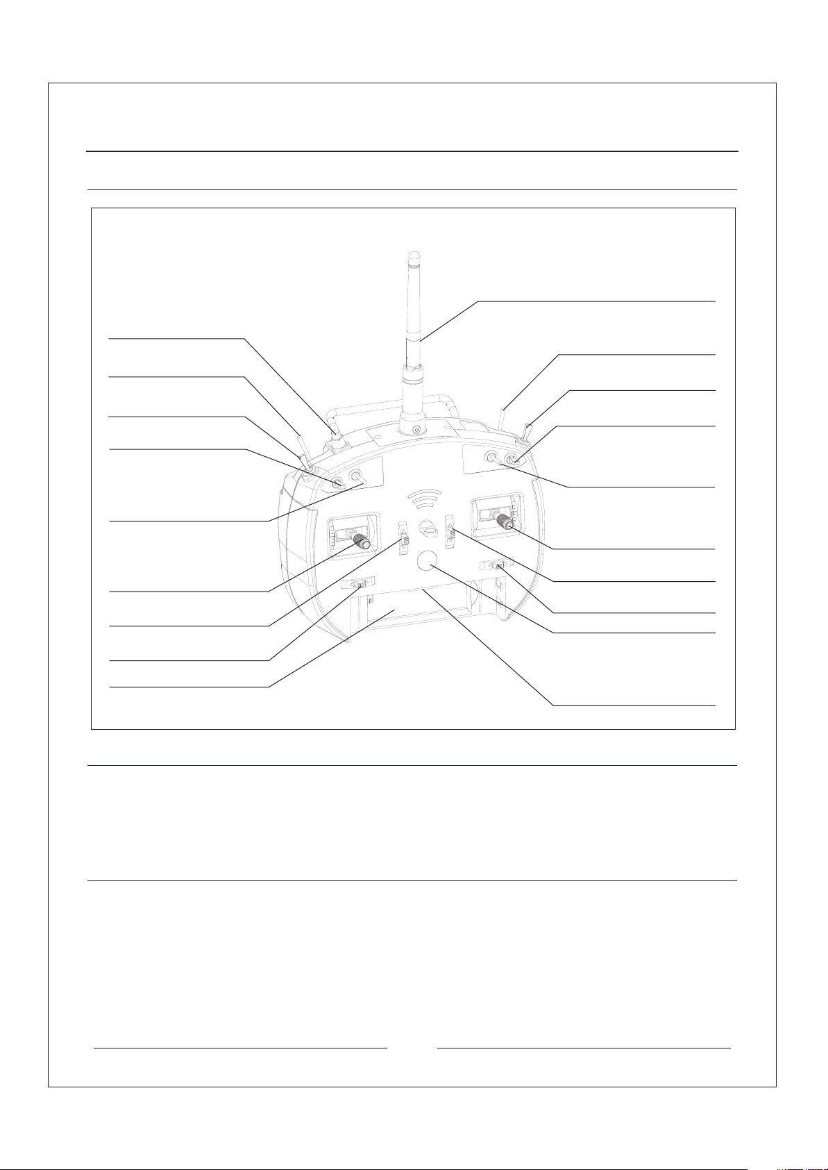
1.Transmitter components introduction
Trainer/Bind
Gear
3D switch (Mode 2/ Mode 4)
Tail Blade pitch (Mode 1/ Mode 3)
Elevator D/R
Antenna
Mix / Hold
3D switch (Mode 1/ Mode 3);
Tail Blade pitch (Mode2 /Mode 4)
Aileron D/R
Aux 1
Flap Gyro
Mode1 elevator and rudder stick
Mode2 throttle and rudder stick
Mode3 elevator and aileron stick
Mode4 throttle and aileron stick
Mode 1 /Mode 3 elevator trim
Mode 2 / Mode 4 throttle trim
Mode 1 / Mode 2 rudder trim
Mode 3 / Mode 4 aileron trim
Transmitter battery box
Mode1 throttle and aileron stick
Mode2 elevator and aileron stick
Mode3 throttle and rudder stick
Mode4 elevator and rudder stick
Mode 1 /Mode 3 throttle trim
Mode 2 / Mode 4 elevator trim
Mode 1 / Mode 2 aileron trim
Mode 3 / Mode 4 rudder trim
Power button
1.LCD setting module connector
2.Wireless Sim USB connector
3.Charging connection wire connector
4.External data connector
2.Transmitter standard and parameters
1)The frequency bandwidth: ISM 2.4GHz (2.400~2.480GHz)
2)number of controller is 6CH
3)The current is not greater than 100 mA (exclude LCD setting module), not greater than 120 mA
(include LCD screen)
4)The battery is Li-Polymer battery (4.2V), the volume is 1100 mAh
3.Product Features
The transmitter is using 2.4G ISM frequency channel, allow auto detection while using the transmitter.
1)
The transmitter receive or distribute the frequency by ID identify technology, protect external jamming,
2)
provide stable and reliable during the operation.
The LCD setting module is dividable, user-friendly and setting the trim easily.
3)
Interchanging interface easily (Change Mode + Menu setting)
4)
Trainer connector is using wireless technology
5)
The power button is using soft material to become the button, it is durable and change the connection
6)
defect while pushing the roller power button
The transmitter is based on the ergonomic technology to design the transmitter
7)
1
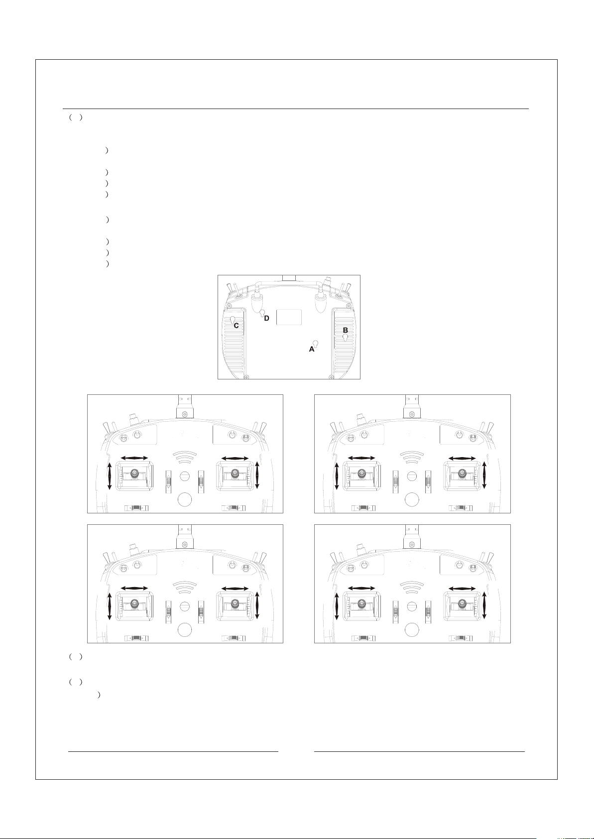
4.Interchanging position of throttle and elevator control
Structural adjustment: Before the adjustment, please take out the four rubber pistons (A, B, C and D) on the back
1
of the transmitter, as shown in the figure
Left Throttle to Right Trottle (Mode 2/Mode 4 to Mode 1/ Mode 3)
1
without friction
2
3
4
1
without friction.
2
3
4
Use a cross-drive screw driver to loosen Screw A. Keep loosening until the stick can move up and down
Tighten Screw B. Keep tightening until the stick can move up and down with rebounds
Loosen Screw C. Keep loosening until the stick can move up and down without rebounds
Tighten Screw D. Keep tightening until the stick can move up and down with friction
Right Throttle to Left Throttle (Mode 1/Mode 3 to Mode 2/ Mode 4)
Use a cross-drive screw driver to loosen Screw D. Keep loosening until the stick can move up and down
1)Tighten Screw C. Keep tightening until the stick can move up and down with rebounds.
Loosen Screw B. Keep loosening until the stick can move up and down without rebounds
Tighten Screw A. Keep tightening until the stick can move up and down with friction
Back view of Transmitter
MODE 1
MODE 2
Rudder Stick
Elevator Stick
MODE 3
Aileron Stick
Elevator Stick
2
Set Control Mode, change of control mode
There are 4 Control Modes: Mode 1, Mode 2, Mode 3 and Mode 4, as shown in the above
3
Changing control mode
1
Push and hold both the R/A Trim (Rubber/Aileron Trim) leftward at the same time then press the Bind button.
Aileron Stick
Throttle Stick
Rudder Stick
Throttle Stick
Rudder Stick
Throttle Stick
MODE 4
Aileron Stick
Throttle Stick
Aileron Stick
Rudder Stick
The transmitter will emit a series of beep sound. That indicates the transmitter has entered the control mode
setting.
Elevator Stick
Elevator Stick
2
 Loading...