

ZONARE Z.one Ultra SP Service Manual

REVISION HISTORY
REV DESCRIPTION DATE
A Initial Release of Service Manual for Z.ONEULTRA SP Product 9/09
B Updated Release to Support 4.3 SW Product Changes 1/10
Q00180 Rev B Page 2 of 244
"Note: Copies are uncontrolled documents - For revision verification see the Master Docum e ntation List"

TABLE OF CONTENTS
1 INTRODUCTION........................................................................................................................................... 9
1.1 Purpose.................................................................................................................................................10
1.2 Product Overview ................................................................................................................................10
1.3 Product Features................................................................................................................................. 11
1.4 Definitions/Acronyms ..........................................................................................................................11
1.5 Documentation Conventions..............................................................................................................13
2 SAFETY .......................................................................................................................................................15
2.1 WARNINGs During Service/Operation.............................................................................................15
2.2 Battery WARNINGs............................................................................................................................. 16
2.3 CAUTIONs During Service................................................................................................................. 16
2.4 Battery CAUTIONs.............................................................................................................................. 17
2.5 USB Memory Stick CAUTIONs .........................................................................................................17
2.6 Networking CAUTION......................................................................................................................... 17
3 SYSTEM SPECIFICATIONS .................................................................................................................... 18
3.1 System Dimensions ................................................................................................................................18
3.2 Displays.................................................................................................................................................18
3.3 Image Archive or Export Storage......................................................................................................19
3.4 Transducers.......................................................................................................................................... 20
3.5 Accessories/Options ............................................................................................................................... 23
3.6 Peripherals............................................................................................................................................ 23
3.7 Site Requirements...............................................................................................................................23
3.8 System Power...................................................................................................................................... 24
3.9 System Power Protection................................................................................................................... 24
3.10 Electrical Specifications..................................................................................................................24
3.11 Temperature, Humidity, Pressure Limits......................................................................................26
3.12 Device Classification .......................................................................................................................26
3.13 Safety Standards.............................................................................................................................. 27
3.14 DICOM Standard..............................................................................................................................27
3.15 Product Labeling..............................................................................................................................27
4 TOP-LEVEL PRODUCT OVERVIEW......................................................................................................30
4.1 Major Assembly Identification............................................................................................................ 30
4.2 Transducers.......................................................................................................................................... 31
Q00180 Rev B Page 3 of 244
"Note: Copies are uncontrolled documents - For revision verification see the Master Docum e ntation List"

4.3 Accessory Components......................................................................................................................32
4.4 SmartCart SP Major Assemblies (shown with MTP Multi- probe Option)...................................33
4.5 SmartCart SP User Interface Controls (Overview)......................................................................... 34
4.6 SP Cart User Interface Controls (Detailed) .....................................................................................35
4.7 SmartCart SP Keyboard Controls (Detailed)...................................................................................39
4.8 Scan Engine User Interface Controls (Detailed).............................................................................42
4.9 SmartCart SP Rear I/O Panel: Layout & Functional Definitions.................................................. 45
4.10 Scanner Rear I/O Ports: Layout & Functional Definitions.........................................................45
4.11 AVED: Audio-Video Extension Device - I/O Panel: (Option)................................................... 46
5 SYSTEM UNCRATING & INSTALLATION PROCEDURES ..............................................................47
5.1 Product Shipment................................................................................................................................47
5.2 Electrical Requirements......................................................................................................................47
5.3 Environmental and Space Requirements........................................................................................47
5.4 Uncrating...............................................................................................................................................47
5.5 Mechanical Verification.......................................................................................................................49
5.6 System Installation:............................................................................................................................. 50
5.7 Transporting - Shipping the Scanner................................................................................................58
6 BASIC SYSTEM CONFIGURATION....................................................................................................... 59
6.1 Basic System Configuration Procedures .........................................................................................59
7 ARCHIVE MENU FUNCTIONS................................................................................................................ 66
7.1 “Media” & “Store/Print” Button Configuration................................................................................... 66
7.2 “Exam Management” Menu................................................................................................................ 69
7.3 “Serial Port” Setup - (Export Calc Report Data).............................................................................. 73
8 DICOM CONFIGURATION....................................................................................................................... 76
8.1 “DICOM” Configuration Overview .....................................................................................................76
8.2 “DICOM” Configuration Parameter Definitions:............................................................................... 77
8.3 Z.ONEULTRA SP Pre-Install Survey Form (Sample Only) ............................................................80
8.4 “DICOM” Configuration Procedure - Menus.................................................................................... 84
8.5 “Network” Setup...................................................................................................................................92
9 ADVANCED SYSTEM SETUP CONFIGURATION.............................................................................. 95
9.1 “Security” Setup Menus...................................................................................................................... 95
9.2 “Power Save” Setup Menu................................................................................................................. 97
10 GENERAL PROCEDURES..................................................................................................................99
Q00180 Rev B Page 4 of 244
"Note: Copies are uncontrolled documents - For revision verification see the Master Docum e ntation List"

10.1 Installing USB Memory Stick, into the Scan Engine................................................................... 99
11 FUNCTIONAL DESCRIPTIONS......................................................................................................... 100
11.1 Overall System............................................................................................................................... 100
11.2 SmartCart SP.................................................................................................................................. 102
12 POWER & SIGNAL DISTRIBUTION DIAGRAMS.......................................................................... 105
12.1 SmartCart SP Power Module Block Diagram (Basic)............................................................... 106
12.2 SmartCart SP Power Module Block Diagram (Detailed).......................................................... 107
12.3 SmartCart SP Main Board Cable Connection Diagram (Original DVD Configuration) .......108
12.4 SmartCart Main Board Cable Connection Diagram (IDE/SATA Adapter DVD Configuration)
109
13 FUNCTIONAL BLOCK DIAGRAMS.................................................................................................. 110
13.1 SmartCart SP Overall System Block Diagram .........................................................................111
14 ASSEMBLY DIAGRAMS..................................................................................................................... 112
14.1 SmartCart SP: Power Module Functional Identification........................................................... 112
15 PERIPHERALS & ACCESSORIES................................................................................................... 113
15.1 DVD/CD Burner - (Internal)"........................................................................................................ 113
15.2 AVED – Audio Video Extension Device Box - (Option)".......................................................... 114
15.3 SONY UP-D897 USB Digital Printer........................................................................................... 120
15.4 SONY UP-D23MD Color Printer..................................................................................................126
15.5 HP LaserJet Network (REPORT) Printer ...................................................................................127
15.6 2- Pedal Footswitch....................................................................................................................... 131
16 SOFTWARE PROCEDURES.............................................................................................................. 132
16.1 Standard Software Installation/Upgrade Procedure................................................................. 132
16.2 “Advanced” Software Installation Procedure .............................................................................134
16.3 SCAN MODULE: Standard Software Installation/Upgrade Procedure..................................137
16.4 SCAN MODULE: “Clean” Software Install Procedure (“Docked”)......................................... 139
16.5 SCAN MODULE: “Clean” Software Install Procedure (“Undocked”) ....................................140
16.6 FTP Site Access: Software/File Downloads from Zonare .....................................................142
16.7 “DIAGNOSTIC” Panel Operations............................................................................................... 142
17 CLEANING AND DISINFECTING PROCEDURES......................................................................... 151
17.1 SmartCart SP.................................................................................................................................. 151
17.2 Scan Engine.................................................................................................................................... 152
17.3 Transducers....................................................................................................................................153
Q00180 Rev B Page 5 of 244
"Note: Copies are uncontrolled documents - For revision verification see the Master Docum e ntation List"

18 MAINTENANCE – CALIBRATION PROCEDURES....................................................................... 157
18.1 Foreword .........................................................................................................................................157
18.2 List: Maintenance Procedures......................................................................................................157
18.3 List: Calibration Procedures......................................................................................................... 157
18.4 Z-PAK “RECONDITION” Procedure - (SmartCartSP)..............................................................158
18.5 UI Lift (Gas spring) Release Cable Adjustment - (SmartCart SP)..........................................159
18.6 Touchscreen Calibration - (Scan Engine).................................................................................. 160
18.7 Display Monitor Adjustment – User Settings .............................................................................162
19 SYSTEM TROUBLESHOOTING........................................................................................................ 164
19.1 Foreword .........................................................................................................................................164
19.2 Technical Support Contact Information...................................................................................... 164
19.3 Troubleshooting.............................................................................................................................. 166
19.4 System Status LED & Error Code Definitions............................................................................ 173
19.5 Scan Engine Fan Operation.........................................................................................................181
19.6 SmartCart SP LCD Display Troubleshooting.............................................................................181
19.7 Battery Performance – Charge Times - Reconditioning ..........................................................182
20 REPAIR PROCEDURES .....................................................................................................................183
20.1 Foreword .........................................................................................................................................183
20.2 Recommended Tools ....................................................................................................................183
20.3 Hardware Service/Replacement Procedures (SmartCart SP)................................................ 184
20.4 Hardware Service/Replacement Procedures (Scan Engine).................................................. 233
20.5 Service Software Procedures....................................................................................................... 234
21 PART NUMBER INFORMATION....................................................................................................... 236
21.1 SmartCart SP.................................................................................................................................. 236
21.2 Scan Engine.................................................................................................................................... 239
21.3 Scan Module................................................................................................................................... 240
21.4 Transducers....................................................................................................................................241
21.5 Peripherals......................................................................................................................................242
22 INDEX .....................................................................................................................................................243
Q00180 Rev B Page 6 of 244
"Note: Copies are uncontrolled documents - For revision verification see the Master Docum e ntation List"

TABLE OF FIGURES
FIGURE 1: LABEL, SCAN MODULE – SERIAL/PART NO........................................................................................................27
FIGURE 2: LABEL, SCAN ENGINE – SERIAL/PART NO..........................................................................................................28
FIGURE 3: LABEL, SCAN ENGINE BATTERY (VERSION 1) - SERIAL/PART NO.....................................................................28
FIGURE 4: LABEL, SCAN ENGINE BATTERY (VERSION 2) - SERIAL/PART NO.....................................................................28
FIGURE 4: LABEL, 100V-240V SMARTCART SP REAR PANEL - SERIAL/PART NO. ..........................................................28
FIGURE 5: LABEL, SMARTCART SP Z-PAK BATTERY.......................................................................................................... 29
FIGURE 6: LABEL, LINEAR ARRAY TRANSDUCERS - SERIAL/PART NO................................................................................29
FIGURE 7: LABEL, CURVED ARRAY TRANSDUCERS - SERIAL/PART NO..............................................................................29
FIGURE 8: LABEL, ENDO CAVITY TRANSDUCER - SERIAL/PART NO. .................................................................................. 29
FIGURE 9: LABEL, PHASED TRANSDUCERS - SERIAL/PART NO..........................................................................................29
FIGURE 10: LABEL, SPECIALTY TRANSDUCERS - SERIAL/PART NO....................................................................................30
FIGURE 11: LABEL, AC POWER BATTERY ADAPTER...........................................................................................................30
FIGURE 12: LABEL, AC POWER ADAPTER POWER SUPPLY................................................................................................30
FIGURE 13: Z.ONEULTRA
FIGURE 14: TRANSDUCER ILLUSTRATIONS ..........................................................................................................................31
FIGURE 15: SMARTCART SP USER INTERFACE CONTROLS (OVERVIEW).......................................................................... 34
FIGURE 16: SP CART USER INTERFACE LAYOUT.................................................................................................................35
FIGURE 17: SMARTCART SP KEYBOARD LAYOUT................................................................................................................39
FIGURE 18: SCAN ENGINE USER INTERFACE LAYOUT (DETAILED).....................................................................................42
FIGURE 19: SMARTCART SP REAR I/O PANEL ...................................................................................................................45
FIGURE 20: SCANNER REAR I/O CONNECTIONS .................................................................................................................45
FIGURE 21: AVED OPTION - I/O PANEL (SMARTCART SP)................................................................................................46
FIGURE 22: MAIN SHIPPING CONTAINER REMOVAL ..............................................................................................................48
FIGURE 23: LOADING RAMP LOWERING................................................................................................................................48
FIGURE 24: REMOVABLE SECTION OF SHIPPING BASE......................................................................................................... 48
FIGURE 25: REMOVING PROTECTIVE STORAGE BAG............................................................................................................ 49
FIGURE 26: BRAKE RELEASE OF WHEELS ............................................................................................................................ 49
FIGURE 27: BATTERY PACK INSTALLATION..........................................................................................................................51
FIGURE 28: SCANNER DOCKING IN SMARTCART SP...........................................................................................................51
FIGURE 29: AC POWER ADAPTER .......................................................................................................................................54
FIGURE 30: 2-BAY BATTERY CHARGER...............................................................................................................................56
FIGURE 31: INSTALLING USB MEMORY STICK.....................................................................................................................99
FIGURE 32: SMARTCART SP: BRAKE MECHANISM............................................................................................................104
FIGURE 33: SMARTCART SP: HEIGHT ADJUSTMENT MECHANISM....................................................................................104
FIGURE 34: SMARTCART SP: POWER MODULE BLOCK DIAGRAM (BASIC)......................................................................106
FIGURE 35: SMARTCART SP: POWER MODULE BLOCK DIAGRAM (DETAILED)...............................................................107
FIGURE 43: SMARTCART: MAIN BOARD CABLE CONNECTION DIAGRAMS (IDE/SATA ADAPTER DVD CONFIGURATION)
....................................................................................................................................................................................109
FIGURE 37: OVERALL SYSTEM BLOCK DIAGRAM - Z.ONEULTRASP..................................................................................111
FIGURE 38: SMARTCART SP: POWER MODULE FUNCTIONS DIAGRAM............................................................................ 112
FIGURE 39: AVED: AUDIO VIDEO EXTENSION DEVICE I/O PANEL DIAGRAM...................................................................116
FIGURE 40: MENU SETTINGS (UP-D897)..........................................................................................................................122
FIGURE 41: OPERATOR CONTROLS (UP-D897) ............................................................................................................... 124
FIGURE 42: APPROVED DISINFECTANTS TABLE (IMMERSION-METHOD)...........................................................................153
FIGURE 43: APPROVED DISINFECTANTS TABLE (WIPE-METHOD).................................................................................... 153
FIGURE 44: TRANSDUCER IMMERSION LIMITS....................................................................................................................155
FIGURE 45: SMARTCART SP 19” DISPLAY: RECOMMENDED SETTINGS...........................................................................162
FIGURE 46: TRANSDUCER CONNECTOR PIN DAMAGE – (EXAMPLE)................................................................................166
MAJOR ASSEMBLY ILLUSTRATIONS ........................................................................................31
SP
Q00180 Rev B Page 7 of 244
"Note: Copies are uncontrolled documents - For revision verification see the Master Docum e ntation List"

Q00180 Rev B Page 8 of 244
"Note: Copies are uncontrolled documents - For revision verification see the Master Docum e ntation List"

1 INTRODUCTION
• USA, Canada, Asia
ZONARE Medical Systems, Inc.
420 N. Bernardo
Mountain View, CA 94043
Toll-free line (in USA only) live-voice support: ................................................. 1-877-913-9663
Standard line (USA & International) live-voice support: ................................... 1-650-316-3199
Tech Support fax line ........................................................................................... 1-650-230-2817
Customer Support E-Mail: ....................... techsupport@zonare.com or salessupport@zonare.com
Web site..................................................www.zonare.com
FTP site (Service) ..................................ftp://12.40.200.87
Toll-free live-phone support: ............. 1-877-913-9663 (5:00AM – 5:00PM, Pacific Standard Time)
Tech Support FAX line ...................... 1-650-230-2817
Tech Support e-mail ........................... techsupport@zonare.com
Corporate web site.............................. www.zonare.com
FTP site (Tech Support Window):
− URL............................................ftp://12.40.200.87
• Enter the following User Name and Password information:
User Name: (call Tech Support for current login information)
Password: (call Tech Support for current login information)
Q00180 Rev B Page 9 of 244
"Note: Copies are uncontrolled documents - For revision verification see the Master Docum e ntation List"

• Europe
ZONARE Medical Systems GmbH
Henkestrasse 91
91052 Erlangen, Germany
Tech Support Phone .......................... (+49) 9131-974 94-0 (8:00AM – 5:00PM)
Tech Support e-mail........................... info@zonare.de
Corporate web site.............................. www.zonare.com
1.1 Purpose
This manual’s purpose is to provide information to assist service personnel in performing the service,
maintenance, and repair procedures that may be required to support ZONARE’s Z.ONEULTRA SP
Diagnostic Ultrasound System product.
1.2 Product Overview
ZONARE’s Z.ONEULTRA SP Ultrasound System provides a full-featured, cart-based ultrasound
system, in a very lightweight package.
The sub-systems that comprise the Z.ONEULTRA SP product are listed below:
• Full-Feature SmartCart SP
• Docked “Scanner” (Scan Engine or Scan Module)
• Ultrasound transducer(s)
The SmartCart SP consists of a limited number of field replaceable units (FRU’s). The FRU’s for
this unit are:
• 19” Display Monitor
• User Interface Assembly
• OLED Sub-Assembly (part of UI)
• Main Board Assembly
• Power Supply Module
• Z-PAK Battery Pack
• Scanner Deck (w/MTP)
Q00180 Rev B Page 10 of 244
"Note: Copies are uncontrolled documents - For revision verification see the Master Docum e ntation List"

• MTP Bolster Plate (or MTP)
• Misc cables and mechanical assemblies
The Z.ONEULTRA SP Ultrasound System is offered with two different configurations of scanner
electronics.
One version being a standalone portable use “Scan Engine” (with local LCD display and user
interface controls), and the other being a “brains only” (non-portable) “Scan Module”.
Scan Engine Scan Module
The ultrasound transducers are replaced as a single FRU, with no field-serviceable parts.
1.3 Product Features
The Z.ONEULTRA SP ultrasound system includes the following key features:
• Full function scanning modalities (B-Scan, M-Mode, Color Flow, Power Doppler, PW
Dopper)
• Remote portability for patient scanning
1.4 Definitions/Acronyms
2D: ................. Two dimensional (B-Mode, Color mode)
BMP: ............. Bit MaP
C: ................... Color Flow Mode (Doppler)
D: ................... Doppler (Pulsed Wave) Mode
DICOM: ........ Digital Imaging and COmmunication in Medicine
DSP:............... Digital Signal Processing
ESD:............... Electro Static Discharge
EV:................. Endo Vaginal
FPGA: ........... Field Programmable Gate Array
FRU: .............. Field Replaceable Unit
Q00180 Rev B Page 11 of 244
"Note: Copies are uncontrolled documents - For revision verification see the Master Docum e ntation List"

HSSL: ............ High Speed Serial Link
LCD:.............. Liquid Crystal Display
LED: .............. Light Emitting Diode
M:................... M-Mode (Motion Mode - Tissue)
NTSC:............ National Television Standards Committee (video standard)
PAL: .............. Phase Alternation by Line (video standard)
PRF:............... Pulse Repetition Frequency
PW:................ Pulsed Wave Mode (Doppler)
Retrospective:.. Post-processing performed on frozen images from memory
SVGA: ........... Super Video Graphics Array
DGC: ............. Depth Gain Compensation
USB:............... Universal Serial Bus
VKB:.............. Virtual KeyBoard
Q00180 Rev B Page 12 of 244
"Note: Copies are uncontrolled documents - For revision verification see the Master Docum e ntation List"

1.5 Documentation Conventions
This following alert conventions are used in this manual:
1.5.1 Alert Messages
1. A WARNING indicates that PERSONAL INJURY OR DEATH may occur to patient and/or
user if the user does not observe the provided information.
WARNING
2. A CAUTION indicates that DAMAGE TO EQUIPMENT may occur if the user does not
observe the provided information.
CAUTION
3. A PRECAUTION indicates that INCONVENIENCE TO THE USER (such as loss of text
entries or saved settings) may result if the user does not observe the provided information.
PRECAUTION
4. Common terms that have a special meaning for the Z.ONEULTRA SP (e.g. Menu Control or
Trackball) are capitalized to distinguish their special usage (as opposed to a person who does
navigation).
5. Control and function names (e.g. Print Button, Image Display) are capitalized for recognition.
6. Items to be acted upon are underlined (e.g. press the Store Button
). Items needing emphasis
are in boldface type.
1.5.2 Symbols
The following symbol conventions are used in this manual, and/or on the Z.ONEULTRA SP product:
This symbol is used to draw attention to information that may relate to safety of the
patient, the operator, or the equipment.
Q00180 Rev B Page 13 of 244
"Note: Copies are uncontrolled documents - For revision verification see the Master Docum e ntation List"

Caution: ESD sensitive
This symbol indicates that the equipment is not
Category AP, and therefore must not
be used in the presence of flammable liquids or gasses.
.
Type BF patient applied part (B= body, F= floating applied part).
This symbol indicates that the equipment does not utilize a floating double insulated
isolation connection, and therefore must not be connected to external equipment that
is not protectively earthed (DO NOT connect to class II equipment).
Storage/Operating Temperature conditions
Direct Current (DC)
Alternating Current (AC)
Date of manufacture
Q00180 Rev B Page 14 of 244
"Note: Copies are uncontrolled documents - For revision verification see the Master Docum e ntation List"
2 SAFETY
It is extremely important to read the following definitions of WARNING information, prior to
beginning any service on any sub-system within the Z.ONEULTRA SP product. As you see
applicability of each of these noted WARNINGs, during the course of the servicing process, be
prepared to avoid harm to persons and equipment by proper adherence.
2.1 WARNINGs During Service/Operation
WARNING
On the miniCart, to prevent possible damage to the 13” display monitor during system
transport (or moving for relocation within the facility) the monitor should first be folded down
to horizontal, rotated to a center position, and “locked” into place using the provided retaining
pin located on the bottom of the display arm.
WARNING
To prevent possible damage to the electronics of the system from condensation, the following
warning must be observed:
Anytime that any Zonare equipment (Scan Engine, SmartCart SP or minCart) is being moved
from an environment that differs greatly in temperature and/or humidity, from the environment
where it has been moved for intended operation, (as a result of shipping or transport) the unit
should be allowed to stand for a period of no less than 30 minutes
powering on.
, prior to inserting battery or
WARNING
WARNING
WARNING
Inspect all cables and power cords BEFORE powering-on the Z.ONEULTRA SP system; or
connecting the transducer. Do not use the system if visual signs of external damage are
observed.
To achieve proper grounding reliability, the Z.ONEULTRA SP SmartCart SP or miniCart power
plug must be fully inserted into a receptacle marked 'Hospital Grade". Do not remove the
grounding wire. If there is any question of power outlet or power cord integrity, do not
proceed. Obtain qualified technical assistance
.
The ZONARE Z.ONEULTRA SP contains no operator-serviceable components within the
enclosures. To avoid electrical shock, the no covers should be removed except by ZONARE
factory trained personnel. Failure to do so may void the system warranty or service contract
coverage
Warnings.
Q00180 Rev B Page 15 of 244
"Note: Copies are uncontrolled documents - For revision verification see the Master Docum e ntation List"
WARNING
Do not operate the Z.ONEULTRA SP system in the presence of flammable anesthetics or in a
room recently washed with flammable cleaning and disinfecting agents. Cleaners can produce
explosive vapors. Check labels of original containers of cleaners and disinfectants for warnings
about vapors. Thoroughly ventilate the room, if such vapors may potentially be present, prior
to activating any of the
Z.ONEULTRA SP components.
2.2 Battery WARNINGs
WARNINGS.
− The battery has a safe smart device. Do not disassemble or alter the battery in any
way.
− Charge the battery at room temperature.
− Do not short-circuit battery by directly connecting the positive and negative terminals
with metal objects.
− Do not heat or discard battery in a fire.
− Do not expose the battery to temperatures above 150 degree F.
− Do not charge the battery near a heat source
− Do not leave battery in direct sunlight
− Recharge battery only using Scan Engine in a docked condition in Z.ONE
SuperCar or miniCartt, or remotely using ZONARE Z.ONE battery charger.
− Do not use a damaged battery.
− Inspect the battery for damage before charging or placing the battery in the
Z.ONE
Ultra
.
− Do not connect battery to an electrical power outlet.
− Do not continue to recharge the battery if it does not recharge fully after 4 hours
− Battery MUST be REMOVED from Scan Engine, during shipping/transport of the
Z.ONE
Ultra
s
2.3 CAUTIONs During Service
CAUTIONS
− Apply proper line voltage. Verify that the Z.ONEULTRA SP system is compatible to
match the AC voltage of site receptacle. Also verify that all plugs match the receptacle
type. Mismatched voltage or plug configuration can damage system components.
Ultra
− Protect the system from water or other liquids that could drip into the electronic
components.
− Do not drop the transducer(s), or allow them to impact any hard surfaces.
Q00180 Rev B Page 16 of 244
"Note: Copies are uncontrolled documents - For revision verification see the Master Docum e ntation List"
− Avoid allowing metal contact pins on connector-end of transducers to come in
contact with foreign surfaces (potential for bending pins).
− Perform no unauthorized modification to any of the Z.ONEULTRA SP sub-systems.
Unauthorized modification can introduce additional hazards to the product.
2.4 Battery CAUTIONs
CAUTIONS
− To protect the battery from potential thermal damage, the system monitors the
temperature of the battery at all times. If the battery is detected as exceeding the
maximum safe operating temperature, a warning message will appear on the display of
the Z.ONE
− To prevent possible damage to the unit, the battery should be REMOVED from the
Scan Engine prior to transport or shipment.
− Do not immerse battery in water or allow it to get wet.
− Do not put the battery into a microwave oven or pressurized container.
− Use only batteries provided by ZONARE
− Store the battery between -20 to 60
Ultra
.
o
Celsius (-4 o to 158
o
F).
− If the battery leaks, emits orders, emits heat, is deformed or discolored in any way
immediately remove it and stop using it.
2.5 USB Memory Stick CAUTIONs
CAUTIONS
USB Memory Sticks that are purchased from outside sources (besides Zonare) may not be
compatible for use in the Z.ONEULTRA SP. USB Memory Sticks which are labeled as
“U3 Smart Technology” on their label or packaging, will NOT be recognized (or
function) in the Z.ONEULTRA SP.
In the case of having one of these incompatible format USB Memory Sticks. There are
freeware U3 Smart Technology “Removal” programs available on the internet, that can
be downloaded and run to make the USB Memory Sticks useable on the Z.ONEULTRA
SP
2.6 Networking CAUTION
CAUTIONS
In order to comply with Electro-Magnetic Compliance it is necessary that the
Z.ONEULTRA SP be connected to available Ethernet resources using a high quality,
shielded CAT-5 cable.
Q00180 Rev B Page 17 of 244
"Note: Copies are uncontrolled documents - For revision verification see the Master Docum e ntation List"

3 SYSTEM SPECIFICATIONS
This section contains Z.ONEULTRA SP system and accessory specifications. For information on
the specifications for ZONARE authorized peripherals, refer to the manufacturers’
documentation.
3.1 System Dimensions
SmartCart SP (with Scan Module installed)
• Height:
- Max operational: 157.5 cm (62 in)
- Min operational: 128 cm (50.5 in)
- Display lowered for transport: 104 cm (41 in)
• Width: 51 cm (20.1 in)
• Depth: 72 cm (28.2 in)
• Weight: 56 kg (122lb.)
Scan Module
• Height: 5.3 cm (2.1 in)
• Width: 22.3 cm (8.8 in)
• Depth: 25 cm (10.0 in)
• Weight: 1.6 kg (3.5 lb)
Scan Engine
• Height: 7.3 cm (2.9 in)
• Width: 18.7 cm (7.4 in)
• Depth: 25 cm (9.8 in)
• Weight: 2.5 kg (5.6 lb) – with battery, no probe
3.2 Displays
SmartCart SP
• 19” high resolution color LCD display
• 1280 x 1024 display format (internal)
• 1280 x 1024 / 800 x 600 video format - configurable (HDMI output)
• 0.41 mm pixel pitch
• Viewing angle (H/V): 170 degrees typical
• Minimum 10:1 contrast
Q00180 Rev B Page 18 of 244
"Note: Copies are uncontrolled documents - For revision verification see the Master Docum e ntation List"

• +/- 90
• 30
• Full 90
o
rotation
o
backward tilt
o
forward tilt into secure transport position
• Advanced setup parameters via on-screen menu
• Integrated system programmed video settings
• Multi-Transducer Port (3 Connectors) - Option
Scan Module
• 640x480 video format (HDMI port)
• USB 2.0 port (one)
• DC power (+12V) input port
Scan Engine
• 5.8” high resolution color LCD display
• 800x480 display format (internal)
• 640x480 video format (HDMI output)
• 0.16 mm pitch
• Manual Brightness and Contrast controls
3.3 Image Archive or Export Storage
IMPORTANT
The image storage capacity numbers listed below apply ONLY to standalone
(undocked) Scan Engine use, or use when docked in a miniCart. In these applications
resolution of the individual image is 640 x 480.
The image storage capactiy numbers, when a Scan Engine (or always with a Scan
Module) is being used while docked in a SmartCart, will be approximately 1/3 less.
This is due to the higher image resolution of 800 x 600 that is used in the
application.
Z.ONEUltra
-------------------------------------------------------------------------------------------------------------------------
Scan Engine - Internal:
- 512MB Internal CompactFlash Storage (Standard)
• DICOM uncompressed: 1280 images
• DICOM RLE: 4060 images
• BMP: 1700 images
- 2GB Internal CompactFlash Storage (Option)
• DICOM uncompressed: 5000 images
Q00180 Rev B Page 19 of 244
"Note: Copies are uncontrolled documents - For revision verification see the Master Docum e ntation List"

• DICOM RLE: 15,900 images
• BMP: 6650 images
-------------------------------------------------------------------------------------------------------------------------
SmartCart SP - Internal:
- Internal Hard Drive (120GB version specs referenced below)
• DICOM uncompressed: 300,000 images
• DICOM RLE: 944,000 images
• BMP: 399,0000 images
- Slimline Internal DVD+RW / CD-RW Drive
• ATAPI Interface
• 24X speed writing for CD-R, DVD+R, or DVD+RW discs
3.4 Transducers
C8-33D 3-D (New @ 4.1SW) ................... (I.D. 140)
• Penetration Depth 24 CM
• Number of Elements 128
• Field of View 79 degrees
• Radius of Curvature 40 mm
• Ultrasound Bandwidth 8-3 MHz
C9-4T Convex ...........................................(I.D. 146)
• Penetration Depth 14 CM
• Number of Elements 128
• Field of View 135 degrees
• Radius of Curvature 11.5 mm
• Ultrasound Bandwidth 9-4 MHz
C9-3 Convex
..............................................(I.D. 130)
• Penetration Depth 18 CM
• Number of Elements 128
• Field of View 67 degrees
• Radius of Curvature 33 mm
• Ultrasound Bandwidth 9-3 MHz
C6-2 Convex .............................................. (I.D. 129)
• Penetration Depth 24 CM
• Number of Elements 128
Q00180 Rev B Page 20 of 244
"Note: Copies are uncontrolled documents - For revision verification see the Master Docum e ntation List"

• Field of View 65 degrees
• Radius of Curvature 50 mm
• Ultrasound Bandwidth 6-2 MHz
C5-2 Convex
............................................ (I.D. 128)
• Penetration Depth 24 CM
• Number of Elements 128
• Field of View 65 degrees
• Radius of Curvature 50 mm
• Ultrasound Bandwidth 4-1 MHz
C4-1 Convex
..............................................(I.D. 2)
• Penetration Depth 30 CM
• Number of Elements 64
• Field of View 80 degrees
• Ultrasound Bandwidth 4-1 MHz
L14-5sp Linear........................................ (I.D. 70)
• Penetration Depth 6 CM
• Number of Elements 128
• Field of View 26 mm
• Ultrasound Bandwidth 14-5 MHz
L14-5W Wide Aperture Linear............. (I.D. 66 or 71)
• Penetration Depth 10 CM
• Number of Elements 192
• Field of View 55 mm
• Ultrasound Bandwidth 14-5 MHz
L12-4V Veterinary
.................................. (I.D. 67)
• Penetration Depth 10 CM
• Number of Elements 128
• Field of View 63 degrees
• Ultrasound Bandwidth 12-4 MHz
L10-5 Linear............................................ (I.D. 64)
• Penetration Depth 10 CM
• Number of Elements 128
• Field of View 38 mm
• Ultrasound Bandwidth 10-5 MHz
Q00180 Rev B Page 21 of 244
"Note: Copies are uncontrolled documents - For revision verification see the Master Docum e ntation List"

L8-3 Linear.............................................. (I.D. 65)
• Penetration Depth 10 CM
• Number of Elements 128
• Field of View 38 mm
• Ultrasound Bandwidth 8-3 MHz
EV9-4 Transvaginal................................ (I.D. 144)
• Penetration Depth 14 CM
• Number of Elements 128
• Field of View 135 degrees
• Radius of Curvature 12 mm
• Ultrasound Bandwidth 9-4 MHz
P10-4 Phased ........................................... (I.D. 7)
• Penetration Depth 14 CM
• Number of Elements 128
• Field of View 80 degrees
• Ultrasound Bandwidth 10-4 MHz
P4-1 Phased ............................................ (I.D. 4)
• Penetration Depth 30 CM
• Number of Elements 128
• Field of View 84 degrees
• Ultrasound Bandwidth 4-1 MHz
P4-1c Phased .............................................(I.D. 5 or 6)
• Penetration Depth 30 CM
• Number of Elements 64
• Field of View 84 degrees
• Ultrasound Bandwidth 4-1 MHz
P8-3 TEE
...................................................(I.D. tbd)
• Penetration Depth 18 CM
• Number of Elements 64
• Ultrasound Bandwidth 7.5-2.7 MHz
A2CW Doppler-Only (New 4.0)
• Number of Elements 2
Q00180 Rev B Page 22 of 244
"Note: Copies are uncontrolled documents - For revision verification see the Master Docum e ntation List"

• Ultrasound Frequency 2.0 MHz
• Ultrasound Bandwidth n/a
A5CW Doppler-Only (New @ 4.1SW) .. (I.D. 513)
• Number of Elements 2
• Ultrasound Frequency 5.0 MHz
• Ultrasound Bandwidth n/a
3.5 Accessories/Options
• 2-Pedal Footswitch (Freeze/Store)
• 2-Bay Battery Charger
• AC Power Adapter
• USB Memory Stick
• AVED (Audio Video Extension Device) Box
o NTSC output:
Horizontal frequency:........................... 15.733 KHz
Vertical frequency: ............................... 59.94 Hz.
o PAL output:
Horizontal frequency:........................... 15.625 KHz
Vertical frequency: ............................... 50.0 Hz.
3.6 Peripherals
SmartCart SP:
On-Board (Mounted) – Local Image Printing
• Sony UP-D897 USB Digital B/W Printer
Off-Board (Un-mounted)
• Sony UP-D23MD Color Printer
• HP LaserJet (PostScript-3 style) Network Printer -------------------- (Report printing only)
3.7 Site Requirements
Power
• 100 – 120VAC, 50-60Hz or 200 – 240VAC, 50-60Hz (Factory Configurable)
Environmental
• Cooling consistent with 1024 BTU / hour system output
o
• Ambient air temperature of 0
– 35o Celsius (32 o - 95 o F)
Q00180 Rev B Page 23 of 244
"Note: Copies are uncontrolled documents - For revision verification see the Master Docum e ntation List"

• Ambient relative humidity of up to 80%, non-condensing
3.8 System Power
• SmartCart SP
- 90 – 120V @ 6A (max)
- 200 – 240V @3A (max)
- Line Frequency: 50 – 60Hz
- 250 W-h - Nickel Metal Hydride (NiMH) battery pack - (Option)
3.9 System Power Protection
• SmartCart SP
- Re-settable AC circuit breaker
3.10 Electrical Specifications
DC Voltages:
• SmartCart SP DC Power Supplies
Voltage Purpose Max Current Rating
+12V VMain Logic Power 12 A
+12V
+7 to +14V
+12 to +25V
VScanner Power 8 A
VFan Power
VAux Power (Peripherals)
variable
Future use
Q00180 Rev B Page 24 of 244
"Note: Copies are uncontrolled documents - For revision verification see the Master Docum e ntation List"

• Scanner Power Board DC Supplies
Voltage Purpose Total Current
+1.2V DSP Power 2.3 A
+1.5V
+1.8V
+2.5V
+3.3V
Vfan
+5.0V
V5.0RTC
+12V
HV1
HV2
HV3
Digital FPGA (Digital Board)
Striker (Analog Board)
FPGA busses
ADC’s
ADC’s and AFE’s
DDR SDRAM 0.30 A
CPU, FPGA’s, etc. 2.5 A
Cooling fans 0.25A
Power Supply monitoring
Levels shifters, muxes, eeprom.
Local power for PIC, etc. 25 mA
Pulsers 170 mA
Probe Mux Bias Power Transducer dependent
Transmit Power (Tissue) User variable
Transmit Power (Doppler) User variable
11.2 A
7.4 A
10 mA
• “Z-Pack” Battery (SmartCart SP) – (Option)
• Battery, 13-cell, 15.6 VDC, 16 A-hours, rechargeable Nickel Metal Hydride battery pack
• Weight: 7.7 lbs.
• Operating range: (values listed are approximations)
- Active use ...................................... At least 1 hour (mode/display brightness dependent)
- Storage mode (in Scan Engine) ..... Less then 50% loss - 1 month
• Battery (Scan Engine Only)
• Battery, 4-cell, 7.4 VDC, 4.4 amp-hours, rechargeable lithium ion battery pack
• Operating range: (values listed are approximations)
- Active use ...................................... 30-40 minutes (mode & display brightness
dependent)
- Standby mode ................................ 2.0-3.0 hours
- Storage mode (in Scan Engine) ..... 3 weeks
• Battery Charger, 2-Bay
• Models:
- Z311: Domestic Version............... 110 VAC power cord
- Z312 : International Version .......220VAC power cord
• Operating Modes:
Q00180 Rev B Page 25 of 244
"Note: Copies are uncontrolled documents - For revision verification see the Master Docum e ntation List"

- CHARGE Mode ...........................1.0 hour (dependent current charge state)
- RECALIBRATE Mode................ 14 hours (discharge->charge->discharge-fully charge)
• Bays:
- Left Bay .........................................Recalibrate or Charge operation
- Right Bay....................................... Charge operation only
• AC Power Adapter (Scan Engine)
• Models:
- Z316 : Domestic Version.............. 110 VAC power cord
- Z317 : International Version .......220 VAC power cord
• Voltage Output
- +9V to +12V..................................+/- 5% over loading
3.11 Temperature, Humidity, Pressure Limits
System: (During Operation):
• Temperature 0
o
to 35o Celsius | (32
o
to 95
o
F)
• Relative Humidity 15–80%
• Elevation 3,100 to (-116) Meters | 10,200 to (-1,250) Feet
System: (During Shipping/Storage):
• Temperature -20 to 60
o
Celsius | (-4 o to 158
o
F)
• Relative Humidity 15–90%
• Elevation 5,944 to (-116) Meters | 19,500 to (-1,250) Feet
3.12 Device Classification
• FDA Class II Device Classification
• CE / MDD Class IIa-rule 10 active device intended for diagnosis
Q00180 Rev B Page 26 of 244
"Note: Copies are uncontrolled documents - For revision verification see the Master Docum e ntation List"
3.13 Safety Standards
All ZONARE instruments, cables, and diagnostic ultrasound imaging transducers have been designed
to meet the essential requirements contained in:
• 93/42/EEC (Medical Device Directive).
In addition, all the above listed equipment meets the following appropriate requirements:
• UL 60601-1 (Standard for Medical Electrical Equipment Part 1: General Requirements for
Safety)
IEC 60601- (Medical Electrical Equipment Part 1: General Requirements for Safety)
•
•
JIS-T-1001 (General Requirements of Medical Electrical Equipment), including limits for
current leakage and isolation from a primary power line
•
Testing for compliance with the essential requirements of the Medical Device Directive has
been performed.
The Z.ONEULTRA SP meets the acoustic output emission guidelines established by the U.S. Food
and Drug Administration (FDA). Acoustic output quantities have been measured, and are displayed, in
accordance with the standards listed under “Guidance Documents”.
3.14 DICOM Standard
• NEMA PS 3.15: 2000, Digital Imaging and Communications in Medicine (DICOM)-Part 15:
Security Profiles
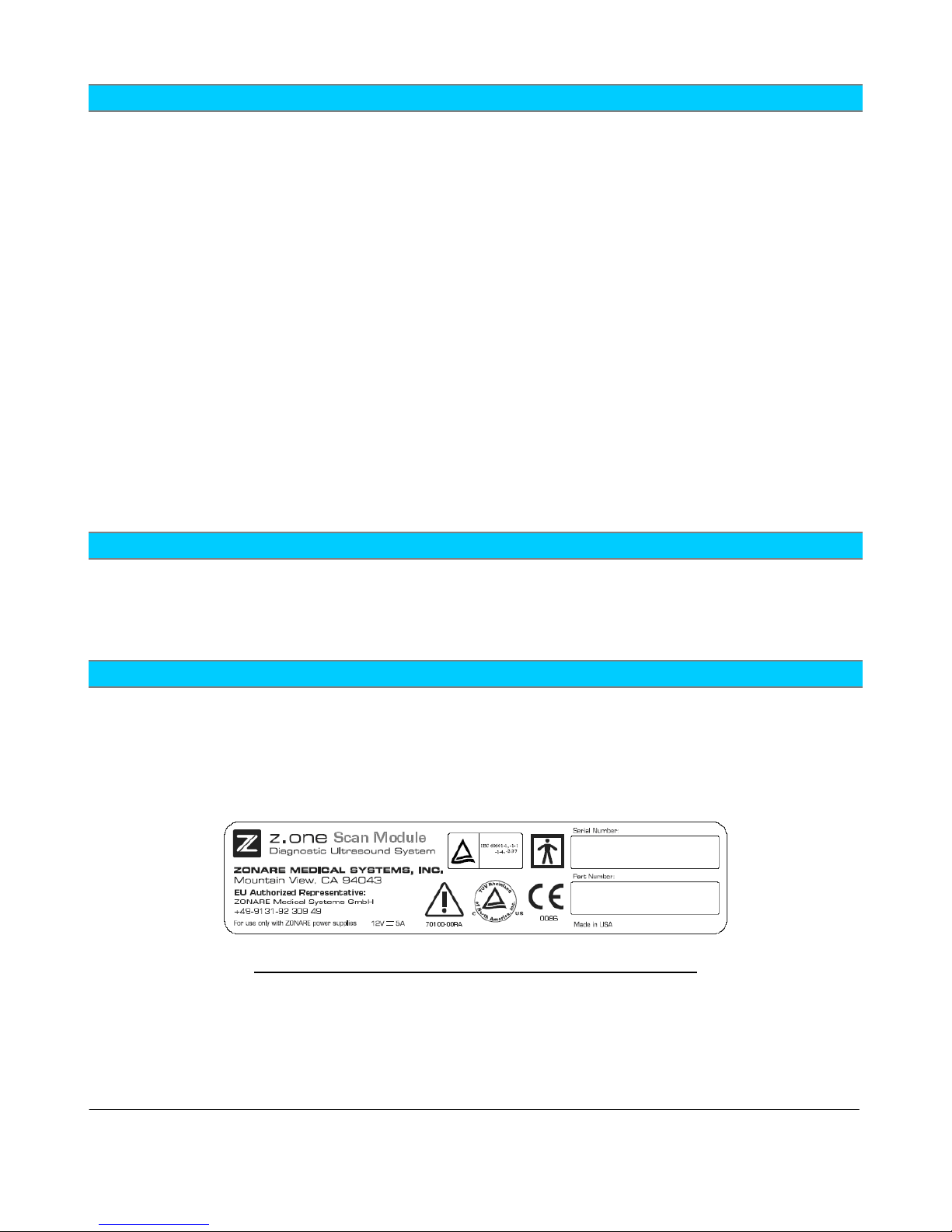
3.15 Product Labeling
The following figures depict the labeling that is required by various regulatory authorities, and
describe their location.
Contact ZONARE if any of these labels are missing or damaged beyond legibility. The Z.ONEULTRA
labels herein are for reference only and are not shown to scale.
SP
Figure 1: Label, Scan Module – Serial/Part No.
Q00180 Rev B Page 27 of 244
"Note: Copies are uncontrolled documents - For revision verification see the Master Docum e ntation List"
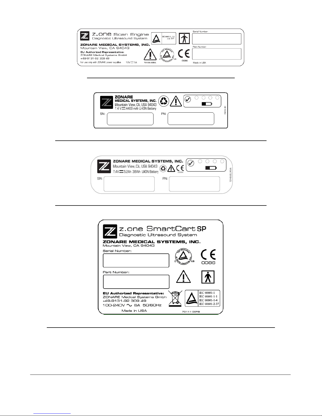
Figure 2: Label, Scan Engine – Serial/Part No.
Figure 3: Label, Scan Engine Battery (Version 1) - Serial/Part No.
Figure 4: Label, Scan Engine Battery (Version 2) - Serial/Part No.
Figure 5: Label, 100V-240V SmartCart SP Rear Panel - Serial/Part No.
Q00180 Rev B Page 28 of 244
"Note: Copies are uncontrolled documents - For revision verification see the Master Docum e ntation List"
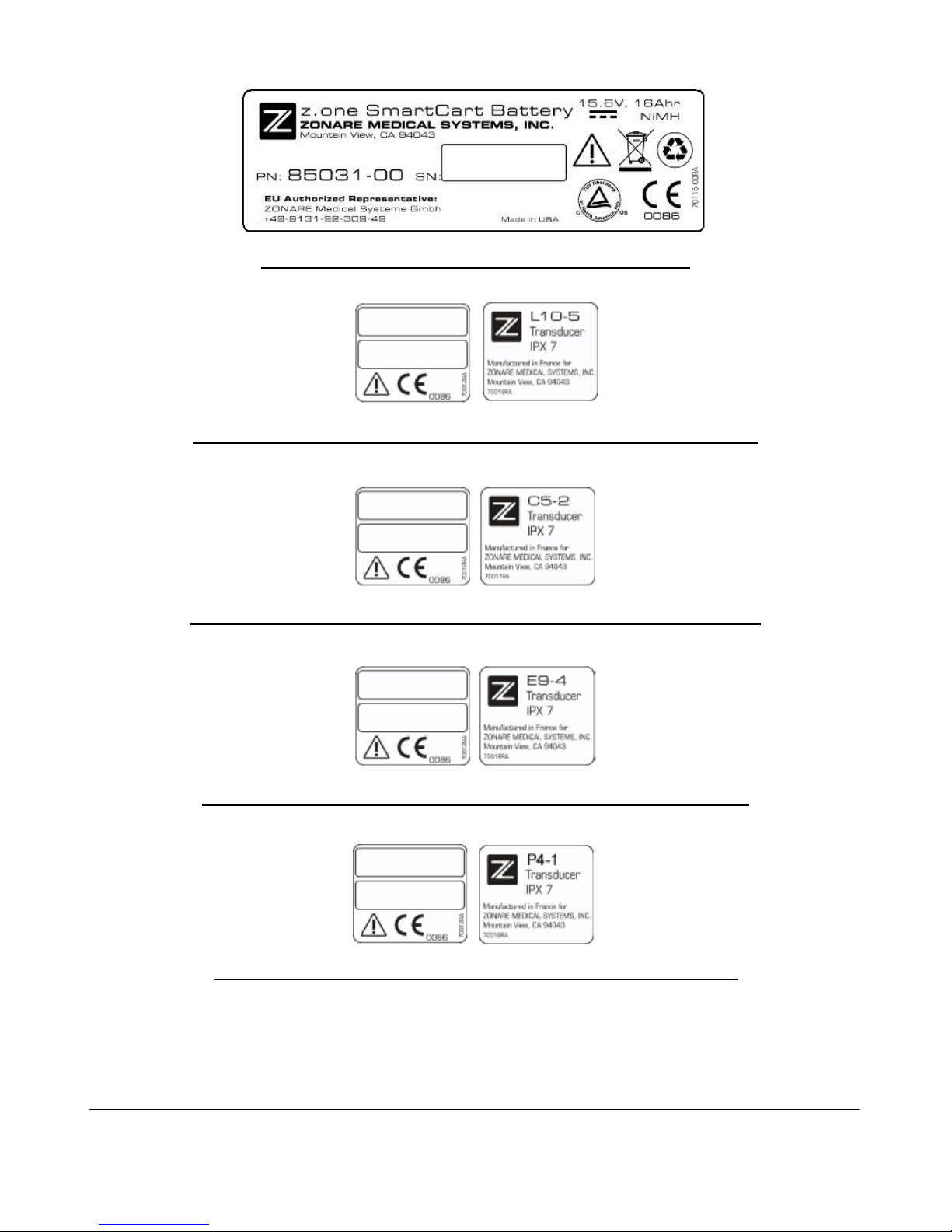
Figure 6: Label, SmartCart SP Z-Pak Battery
Figure 7: Label, Linear Array Transducers - Serial/Part No.
Figure 8: Label, Curved Array Transducers - Serial/Part No.
Figure 9: Label, Endo Cavity Transducer - Serial/Part No.
Figure 10: Label, Phased Transducers - Serial/Part No.
Q00180 Rev B Page 29 of 244
"Note: Copies are uncontrolled documents - For revision verification see the Master Docum e ntation List"

Figure 11: Label, Specialty Transducers - Serial/Part No.
Figure 12: Label, AC Power Battery Adapter
Figure 13: Label, AC Power Adapter Power Supply
4 TOP-LEVEL PRODUCT OVERVIEW
4.1 Major Assembly Identification
Q00180 Rev B Page 30 of 244
"Note: Copies are uncontrolled documents - For revision verification see the Master Docum e ntation List"
 Loading...