

Zonare Z.one Ultrasound 2.0 User manual

REVISION HISTORY
REV DESCRIPTION DATE
A Initial Release of Version 2.0 Product, Service Manual 8/06
Q00110 Rev A 8/06 Page 2 of 225
"Note: Copies are uncontrolled documents - For revision verification see the Master Docum e ntation List"

TABLE OF CONTENTS
1 INTRODUCTION .......................................................................................................................................13
1.1 Purpose...................................................................................................................................................13
1.2 Product Overview...................................................................................................................................13
1.3 Product Features.....................................................................................................................................14
1.4 Definitions/Acronyms............................................................................................................................14
1.5 Documentation Conventions..................................................................................................................16
1.5.1 Alert Messages................................................................................................................................16
1.5.2 Symbols ...........................................................................................................................................16
2 SAFETY .......................................................................................................................................................18
2.1 WARNINGs During Service/Operation.................................................................................................18
2.2 Battery WARNINGs ..............................................................................................................................19
2.3 CAUTIONs During Service...................................................................................................................19
2.4 Battery CAUTIONs................................................................................................................................20
2.5 USB Memory Stick CAUTIONs............................................................................................................20
3 SYSTEM SPECIFICATIONS....................................................................................................................21
3.1 System Dimensions................................................................................................................................21
3.2 Displays..................................................................................................................................................21
3.3 Image Storage.................................................................................................................. .......................22
3.4 Transducers ............................................................................................................................................23
3.5 Accessories.............................................................................................................................................24
3.6 Peripherals..............................................................................................................................................24
3.7 Imaging Modalities.................................................................................................................................24
3.8 Site Requirements...................................................................................................................................27
3.9 System Power.........................................................................................................................................27
3.10 System Power Protection....................................................................................................................28
3.11 Electrical Specifications .....................................................................................................................28
3.12 Temperature, Humidity, Pressure Limits............................................................................................30
3.13 Device Classification..........................................................................................................................30
3.14 Safety Standards .................................................................................................................................30
3.15 DICOM Standard................................................................................................................................31
3.16 Product Labeling.................................................................................................................................31
4 TOP-LEVEL PRODUCT OVERVIEW....................................................................................................35
Q00110 Rev A 8/06 Page 3 of 225
"Note: Copies are uncontrolled documents - For revision verification see the Master Docum e ntation List"

4.1 Major Assembly Identification...............................................................................................................35
4.2 Transducers ............................................................................................................................................35
4.3 Accessory Components..........................................................................................................................36
4.4 SuperCart User Interface Controls (Overview)......................................................................................37
4.5 Scan Engine User Interface Controls (Overview)..................................................................................38
4.6 SuperCart User Interface Controls (Detailed)........................................................................................39
4.6.1 SuperCart User Interface Functions...............................................................................................40
4.7 SuperCart & miniCart Keyboard Controls (Detailed)............................................................................44
4.8 Scan Engine User Interface Controls (Detailed) ....................................................................................47
4.8.1 Scan Engine User Interface Functions............................................................................................47
4.9 SuperCart Rear I/O Panel: Layout & Functional Definitions................................................................50
4.9.1 Functions: I/O Board Connectors...................................................................................................50
4.9.2 Functions: Main Board Connectors................................................................................................50
4.10 miniCart I/O Connections: Layout & Functional Definitions............................................................51
4.10.1 Functions: I/O Port Connectors......................................................................................................51
4.11 Scan Engine (2.0) Rear I/O Connections: Layout & Functional Definitions ....................................51
4.11.1 Functions: I/O Port Connectors......................................................................................................51
5 SYSTEM UNCRATING & INSTALLATION PROCEDURES.............................................................53
5.1 Product Shipment...................................................................................................................................53
5.2 Electrical Requirements..........................................................................................................................53
5.3 Environmental and Space Requirements................................................................................................ 53
5.4 Uncrating................................................................................................................................................53
5.4.1 SuperCart:.......................................................................................................................................53
5.4.2 miniCart:.........................................................................................................................................55
5.5 Mechanical Verification.........................................................................................................................56
5.6 System Installation:................................................................................................................................57
5.6.1 Initial Checks ..................................................................................................................................57
5.6.2 Installing the Lithium-Ion Battery Pack, into the Scan Engine.......................................................57
5.6.3 Docking Scan Engine into SuperCart .............................................................................................58
5.6.4 Docking Scan Engine on miniCart..................................................................................................58
5.6.5 Powering-ON the
z.one
..................................................................................................................59
5.6.5.1 SuperCart Power-ON.................................................................................................................................59
5.6.5.2 Scan Engine (System Complete) Power-ON ..............................................................................................60
5.6.6 Powering-OFF the
Q00110 Rev A 8/06 Page 4 of 225
"Note: Copies are uncontrolled documents - For revision verification see the Master Docum e ntation List"
z.one
System....................................................................................................60

5.6.6.1 Scan Engine Power-OFF...........................................................................................................................60
5.6.6.2 SuperCart Power-OFF...............................................................................................................................61
5.6.7 AC Power Adapter: Use & Operation ............................................................................................61
5.6.8 2-Bay Battery Charger: Use & Operation......................................................................................62
5.6.8.1 “Recalibrating” Battery Packs..................................................................................................................63
5.6.8.2 Charging Battery Packs.............................................................................................................................64
5.7 Transporting - Shipping the Scan Engine...............................................................................................65
6 BASIC SYSTEM CONFIGURATION......................................................................................................66
6.1 Basic System Configuration Procedures................................................................................................66
•
Entering “INSTITUTION” (Hospital) Name .........................................................................................66
•
Entering “TIME / DATE” Information ..................................................................................................67
•
Configuring “AUDIO/VIDEO” Setup....................................................................................................67
•
Configuring “IDLE MODE” (Power-Saver Mode) Configuration .......................................................68
7 ARCHIVE (MEDIA – PRINT/STORE) CONFIGURATION ................................................................70
7.1 ARCHIVE Configuration.......................................................................................................................70
•
“MEDIA” (REMOVABLE) Configuration.............................................................................................71
•
“PRINT/STORE” Configuration............................................................................................................72
8 DICOM CONFIGURATION .....................................................................................................................73
8.1 “DICOM” Configuration Overview.......................................................................................................73
8.2 “DICOM” Configuration Parameter Definitions: (Z-ONE)....................................................................74
8.3 Z.ONE Pre-Install Survey Form (Sample Only).....................................................................................76
8.4 “DICOM” Configuration Procedure - Menus ........................................................................................80
•
DICOM” GENERAL” Configuration ....................................................................................................80
•
DICOM “PRINTERS” Configuration...................................................................................................81
•
DICOM” NETWORK STORE” Configuration ......................................................................................82
•
DICOM” MPPS” (Modality Performed Procedure Step) Configuration..............................................83
•
DICOM” WORKLIST” Configuration...................................................................................................84
9 ADVANCED SYSTEM SETUP CONFIGURATION..............................................................................86
9.1 “Security” Setup Menus.........................................................................................................................86
9.2 “Network” Setup ....................................................................................................................................87
9.3 “Serial Port” Setup .................................................................................................................................88
10 GENERAL PROCEDURES ..................................................................................................................90
10.1 Installing USB Memory Stick, into the Scan Engine .........................................................................90
Q00110 Rev A 8/06 Page 5 of 225
"Note: Copies are uncontrolled documents - For revision verification see the Master Docum e ntation List"

11 FUNCTIONAL DESCRIPTIONS..........................................................................................................91
11.1 Overall System....................................................................................................................................91
11.1.1 Features Overview ..........................................................................................................................91
11.1.2 Electronics Overview (Scan Engine)..............................................................................................92
11.2 SuperCart............................................................................................................................................93
11.2.1 PC Board Descriptions...................................................................................................................93
1. Main/IO Board Zonare P/N: 80207....................................................................................................93
2. Backplane (Interface) Board Zonare P/N: 80127 ..............................................................................94
3. Scan Engine Interface Board Zonare P/N: 80136..............................................................................94
11.2.2 Electro and Mechanical Assemblies ...............................................................................................95
1. Brake Mechanism ...............................................................................................................................95
2. Height Adjustment Mechanism...........................................................................................................96
12 POWER & SIGNAL DISTRIBUTION DIAGRAMS ..........................................................................97
12.1 SuperCart AC/DC Power Distribution Diagram.................................................................................98
12.2 SuperCart AC Board Schematic .........................................................................................................99
12.3 miniCart AC/DC Power Distribution Diagram.................................................................................100
13 FUNCTIONAL BLOCK DIAGRAMS ................................................................................................101
13.1 z.one Overall System Block Diagram (SuperCart Configuration)...................................................102
13.2 z.one Overall System Block Diagram (miniCart Configuration).....................................................103
14 ASSEMBLY DIAGRAMS.....................................................................................................................104
14.1 SuperCart: AC/DC Power Component Identification.......................................................................104
15 PERIPHERALS.....................................................................................................................................105
15.1 SONY UP-897MD B/W Printer .......................................................................................................105
15.1.1 Installation Notes..........................................................................................................................105
15.1.2 Installation Procedure ..................................................................................................................105
Print Button Configuration (Trigger)..............................................................................................................112
Print Verification .............................................................................................................................................113
15.2 PANASONIC LQ-MD800 Video Recorder (DVD).........................................................................114
15.2.1 Installation Notes..........................................................................................................................114
15.2.2 Installation Procedure ..................................................................................................................114
15.3 SONY UP-21MD Color Printer........................................................................................................121
15.3.1 Installation Notes:.........................................................................................................................121
15.3.2 Installation Procedure:.................................................................................................................121
Q00110 Rev A 8/06 Page 6 of 225
"Note: Copies are uncontrolled documents - For revision verification see the Master Docum e ntation List"

Initial Mounting and Basic Setup....................................................................................................................121
15.4 SONY UP-D897 USB Digital Printer (miniCart Only)....................................................................127
15.4.1 Installation Notes:.........................................................................................................................127
15.4.2 Installation Procedure:.................................................................................................................127
Print Button Configuration (Trigger)..............................................................................................................130
Operator Controls............................................................................................................................................131
16 SOFTWARE PROCEDURES ..............................................................................................................132
16.1 Standard Software Installation/Upgrade Procedure..........................................................................132
16.2 “Advanced” Software Installation Procedure...................................................................................135
16.2.1 Interrupting the normal boot sequence (“Alternate Boot Options”):...........................................135
16.2.2 Advanced Install Operations: .......................................................................................................136
16.3 FTP Site Access: Software/File Downloads from Zonare..............................................................138
16.4 “DIAGNOSTIC” Panel Operations..................................................................................................139
16.4.1 Foreword.......................................................................................................................................139
16.4.2 Accessing the basic “Diagnostic” Panel......................................................................................140
16.4.3 PC Board Version Information.....................................................................................................140
16.4.4 FTP Remote Access Configuration: (Zonare Support).................................................................141
16.4.5 AUTOMATIC System Log Files – Download to ZONARE ...........................................................141
16.4.6 MANUAL Log File Capture (Store) – Download to ZONARE.....................................................142
16.4.7 MANUAL Log File Capture (During “System Lock-Up”) – Download to ZONARE...................143
16.4.8 MANUAL Image File Capture (Store) – Download to ZONARE .................................................143
16.4.9 Remote Software Upgrade (download) from ZONARE site..........................................................144
16.4.10 Advanced Service “Diagnostic” Panel Function......................................................................145
16.4.10.1 Accessing the “Advanced” Diagnostic Functions (Password Entry)..................................................145
16.4.10.2 Utilizing the “System Console” ...........................................................................................................146
17 CLEANING AND DISINFECTING PROCEDURES........................................................................148
17.1 SuperCart..........................................................................................................................................148
17.1.1 Cleaning Barco LCD Display.......................................................................................................148
17.1.2 Cleaning the SuperCart exterior surfaces.....................................................................................149
17.2 Scan Engine......................................................................................................................................149
17.2.1 Cleaning LCD Display..................................................................................................................149
17.3 Transducers.......................................................................................................................................150
17.3.1 Cleaning – Care of Transducers...................................................................................................150
17.3.1.1 Approved disinfectants.........................................................................................................................150
Q00110 Rev A 8/06 Page 7 of 225
"Note: Copies are uncontrolled documents - For revision verification see the Master Docum e ntation List"

17.3.2 Cleaning – Disinfecting Procedures.............................................................................................150
17.3.2.1 Wipe Method ........................................................................................................................................150
17.3.2.2 Immersion Method ...............................................................................................................................151
18 MAINTENANCE – CALIBRATION PROCEDURES......................................................................153
18.1 Foreword...........................................................................................................................................153
18.2 List: Maintenance Procedures...........................................................................................................153
18.3 List: Calibration Procedures .............................................................................................................153
18.4 UI Lift (Gas Shock) Release Cable Adjustment - (SuperCart).........................................................154
18.4.1 Gaining access to cable adjuster ..................................................................................................154
18.4.2 Cable adjustment (Barrel adjuster)...............................................................................................154
18.5 Touchscreen Calibration - (Scan Engine).........................................................................................155
18.5.1 Calibration Procedure..................................................................................................................155
18.5.2 Verifying Calibration....................................................................................................................156
18.6 LCD Display Monitor Adjustment – User Settings (miniCart Only) ...............................................157
18.6.1 miniCart LCD Display User Settings Adjustment.........................................................................157
18.7 LCD Display Monitor Adjustment - Calibration (SuperCart Only).................................................158
18.7.1 Basic Adjustment...........................................................................................................................158
18.7.2 “OSD”- Advanced Menu Calibration Procedure.........................................................................158
18.7.3 Display Replacement Only: “Full AutoSet” Service Procedure...................................................161
19 SYSTEM TROUBLESHOOTING.......................................................................................................166
19.1 Foreword...........................................................................................................................................166
19.2 Technical Support Contact Information............................................................................................166
19.3 Troubleshooting................................................................................................................................167
19.3.1 Power-On Problems......................................................................................................................167
19.3.2 System Start-Up Problems ............................................................................................................167
19.3.3 Peripheral Problems.....................................................................................................................168
19.3.4 Transducer Problems....................................................................................................................169
19.3.5 Battery Charging Problems ..........................................................................................................169
19.3.6 Imaging Problems.........................................................................................................................169
19.3.7 General Operation Problems........................................................................................................170
19.3.8 DICOM Connectivity/Communications Problems........................................................................171
19.4 System Status LED Definitions........................................................................................................172
19.4.1 SuperCart......................................................................................................................................172
19.4.1.1 Rear I/O Panel .....................................................................................................................................172
Q00110 Rev A 8/06 Page 8 of 225
"Note: Copies are uncontrolled documents - For revision verification see the Master Docum e ntation List"

19.4.1.2 Scan Engine Interface Board (Scanner Pocket area) ..........................................................................174
19.4.2 Scan Engine...................................................................................................................................175
19.5 Scan Engine Fan Operation ..............................................................................................................177
19.6 SuperCart LCD Display (Barco) Troubleshooting ...........................................................................177
19.6.1 Image display quality problems ....................................................................................................177
20 REPAIR PROCEDURES......................................................................................................................178
20.1 Foreword...........................................................................................................................................178
20.2 Recommended Tools ........................................................................................................................178
20.3 Hardware Service/Replacement Procedures (SuperCart) .................................................................179
20.3.1 Main - I/O Board Assembly - Removal/Replacement (SuperCart) ...............................................179
20.3.2 13” LCD (Barco) Display - Removal/Replacement (SuperCart)..................................................181
20.3.3 User Interface Assembly - Removal/Replacement (SuperCart) ....................................................183
20.3.4 Speaker Assembly - Removal/Replacement (SuperCart)...............................................................184
20.3.5 Scan Engine Pocket Assembly - Removal/Replacement (SuperCart)...........................................188
20.3.6 HSSL Cable - Removal/Replacement (SuperCart)........................................................................189
20.3.7 Backplane Board Assy - Removal/Replacement (SuperCart) .......................................................190
20.3.8 Speaker Assembly - Removal/Replacement (SuperCart)................... Error! Bookmark not defined.
20.3.9 Brake Push-Cam - Removal/Replacement (SuperCart)................................................................195
20.3.10 Casters - Removal/Replacement (SuperCart)............................................................................196
20.3.11 SuperCart Power Supplies ........................................................................................................199
20.3.11.1 AC Power Board - Removal/Replacement (SuperCart).......................................................................200
20.3.11.2 DC Power Supply - Removal/Replacement (SuperCart)......................................................................200
20.4 Hardware Service/Replacement Procedures (miniCart)....................................................................202
20.4.1 Main AC Power Fuse Removal/Replacement (miniCart) .............................................................202
20.4.2 Main Power Supply – Removal/Replacement (miniCart) .............................................................203
20.4.3 USB Hub Service – Removal/Replacement (miniCart).................................................................205
20.4.4 Remote Keyboard Assy - Removal/Replacement (miniCart).........................................................207
20.4.5 LCD Display - Removal/Replacement (miniCart).........................................................................208
20.4.6 Casters/Wheels - Removal/Replacement (miniCart).....................................................................210
20.5 Hardware Service/Replacement Procedures (Scan Engine) .............................................................212
20.5.1 Rear I/O Door Assembly - Removal/Replacement (Scan Engine).................................................212
20.6 Service Software Procedures ............................................................................................................213
20.6.1 Accessing the “Diagnostics” Menu ..............................................................................................213
21 PART NUMBER INFORMATION .....................................................................................................214
Q00110 Rev A 8/06 Page 9 of 225
"Note: Copies are uncontrolled documents - For revision verification see the Master Docum e ntation List"

21.1 SuperCart..........................................................................................................................................214
21.1.1 Major FRU Assemblies .................................................................................................................214
21.1.2 Discrete PC Boards.......................................................................................................................214
21.1.3 Cables............................................................................................................................................215
21.1.4 SuperCart Miscellaneous Items ....................................................................................................215
21.2 miniCart ............................................................................................................................................217
21.2.1 miniCart Major FRU Assemblies..................................................................................................217
21.2.2 miniCart Cables............................................................................................................................ 217
21.2.3 miniCart Miscellaneous Items.......................................................................................................218
21.3 Scan Engine......................................................................................................................................219
21.3.1 Major FRU Assemblies & Miscellaneous.....................................................................................219
21.3.2 Scan Engine Accessories...............................................................................................................219
21.3.3 Scan Engine Miscellaneous Items.................................................................................................220
21.4 Transducers.......................................................................................................................................221
21.4.1 Transducers (Complete Assemblies).............................................................................................221
21.4.2 Transducers Accessories...............................................................................................................221
21.5 Peripherals – Kits - Cables................................................................................................................222
22 INDEX.....................................................................................................................................................224
Q00110 Rev A 8/06 Page 10 of 225
"Note: Copies are uncontrolled documents - For revision verification see the Master Docum e ntation List"

TABLE OF FIGURES
FIGURE 1: LABEL, SCAN ENGINE – SERIAL/PART NO..........................................................................................................31
FIGURE 2: LABEL, BATTERY - MODEL/SERIAL NO...............................................................................................................31
FIGURE 3: LABEL, 100-120V SUPERCART REAR PANEL - MODEL/SERIAL NO...................................................................32
FIGURE 4: LABEL, 200-240V SUPERCART REAR PANEL - MODEL/SERIAL NO...................................................................32
FIGURE 5: LABEL, MINICART REAR PANEL - MODEL/SERIAL NO..........................................................................................32
FIGURE 6: LABEL, 100-120V SUPERCART BACKPACK OUTLET STRIP ..............................................................................32
FIGURE 7: LABEL, 200-240V SUPERCART BACKPACK OUTLET STRIP ..............................................................................33
FIGURE 8: LABEL, L10-5 LINEAR ARRAY TRANSDUCER (S/N & P/N)................................................................................. 33
FIGURE 9: LABEL, L8-3 LINEAR ARRAY TRANSDUCER (S/N & P/N)...................................................................................33
FIGURE 10: LABEL, C5-2 CURVED ARRAY TRANSDUCER (S/N & P/N)..............................................................................33
FIGURE 11: LABEL, E9-4 ENDO VAGINAL TRANSDUCER (S/N & P/N)................................................................................ 33
FIGURE 12: LABEL, P4-1 PHASED TRANSDUCER (S/N & P/N)...........................................................................................34
FIGURE 13: LABEL, P10-4 PHASED TRANSDUCER (S/N & P/N).........................................................................................34
FIGURE 14: LABEL, AC POWER BATTERY ADAPTER...........................................................................................................34
FIGURE 15: LABEL, AC POWER ADAPTER POWER SUPPLY................................................................................................34
FIGURE 16: Z.ONE MAJOR ASSEMBLY ILLUSTRATIONS........................................................................................................ 35
FIGURE 17: TRANSDUCER ILLUSTRATIONS ..........................................................................................................................36
FIGURE 18: ACCESSORIES ...................................................................................................................................................36
FIGURE 19: SUPERCART USER INTERFACE CONTROLS (OVERVIEW) ................................................................................37
FIGURE 20: SCAN ENGINE USER INTERFACE CONTROLS (OVERVIEW)...............................................................................38
FIGURE 21: SUPERCART USER INTERFACE LAYOUT............................................................................................................39
FIGURE 22: SUPERCART KEYBOARD LAYOUT......................................................................................................................44
FIGURE 23: MINICART KEYBOARD LAYOUT...........................................................................................................................44
FIGURE 24: SCAN ENGINE USER INTERFACE LAYOUT (DETAILED).....................................................................................47
FIGURE 25: SUPERCART REAR I/O PANEL..........................................................................................................................50
FIGURE 26: MINICART USB HUB CONNECTIONS.................................................................................................................51
FIGURE 27: SCAN ENGINE (2.0) REAR I/O CONNECTIONS .................................................................................................51
FIGURE 28: MAIN SHIPPING CONTAINER REMOVAL .............................................................................................................. 54
FIGURE 29: LOADING RAMP LOWERING................................................................................................................................54
FIGURE 30: REMOVABLE SECTION OF SHIPPING BASE......................................................................................................... 54
FIGURE 31: BRAKE RELEASE OF WHEELS ............................................................................................................................55
FIGURE 32: BATTERY PACK INSTALLATION..........................................................................................................................58
FIGURE 33: SCAN ENGINE TO SUPERCART DOCKING.........................................................................................................58
FIGURE 34: SCAN ENGINE TO MINICART DOCKING..............................................................................................................59
FIGURE 35: SUPERCART: AC POWER CIRCUIT BREAKER ..................................................................................................59
FIGURE 36: SCAN ENGINE: POWER ON/OFF .....................................................................................................................60
FIGURE 37: AC POWER ADAPTER .......................................................................................................................................62
FIGURE 38: 2-BAY BATTERY CHARGER...............................................................................................................................63
FIGURE 39: INSTALLING USB MEMORY STICK.....................................................................................................................90
FIGURE 40: SUPERCART: BRAKE MECHANISM....................................................................................................................96
FIGURE 41: SUPERCART: HEIGHT ADJUSTMENT MECHANISM............................................................................................96
FIGURE 42: SUPERCART: AC/DC POWER DISTRIBUTION DIAGRAM ..................................................................................98
FIGURE 43: SUPERCART: AC BOARD SCHEMATIC..............................................................................................................99
FIGURE 44: MINICART: AC/DC POWER DISTRIBUTION DIAGRAM..................................................................................... 100
FIGURE 45: OVERALL SYSTEM BLOCK DIAGRAM (2.0 SCAN ENGINE & SUPERCART).....................................................102
FIGURE 46: OVERALL SYSTEM BLOCK DIAGRAM (2.0 SCAN ENGINE & MINICART)..........................................................103
FIGURE 47: SUPERCART: AC/DC COMPONENT LOCATION DIAGRAM..............................................................................104
FIGURE 48: MENU SETTINGS (UP-897MD)......................................................................................................................107
FIGURE 49: UP-897MD REAR PANEL VIEW .....................................................................................................................109
FIGURE 50: CABLE CONNECTIONS (UP-897MD)..............................................................................................................110
FIGURE 51: CABLE CONNECTIONS (CART REAR I/O)........................................................................................................112
FIGURE 52: LQ-MD800 INSTALLATION..............................................................................................................................116
Q00110 Rev A 8/06 Page 11 of 225
"Note: Copies are uncontrolled documents - For revision verification see the Master Docum e ntation List"

FIGURE 53: LQ-MD800 FINAL MOUNTING........................................................................................................................116
FIGURE 54: CABLE CONNECTIONS DIAGRAM (LQ-MD800)..............................................................................................117
FIGURE 55: CABLE CONNECTIONS DIAGRAM (CART REAR I/O) .......................................................................................120
FIGURE 56: TEMPORARY SETUP – SONY MENU VIEWING CABLING CONNECTIONS.........................................................125
FIGURE 57: UP-21MD FINAL CABLE CONNECTIONS ........................................................................................................ 126
FIGURE 58: MENU SETTINGS (UP-D897)..........................................................................................................................128
FIGURE 59: CABLE CONNECTIONS (UP-D897).................................................................................................................129
FIGURE 60: OPERATOR CONTROLS (UP-D897) ...............................................................................................................131
FIGURE 61: APPROVED DISINFECTANTS TABLE................................................................................................................150
FIGURE 62: TRANSDUCER IMMERSION LIMITS ...................................................................................................................151
FIGURE 63: BARCO DISPLAY - “OSD” MENU SPECIFICATIONS TABLE ...........................................................................165
FIGURE 64: SUPERCART BACKPACK OVERALL POWER CONNECTIONS DIAGRAM ......................................................... 199
Q00110 Rev A 8/06 Page 12 of 225
"Note: Copies are uncontrolled documents - For revision verification see the Master Docum e ntation List"

1 INTRODUCTION
ZONARE Medical Systems, Inc.
1061 Terra Bella Avenue
Mountain View, CA 94043-1839
Toll-free line (in USA only) live-voice support: ................................................. 1-877-913-9663
Standard line (USA & International) live-voice support: ................................... 1-650-316-3199
Tech Support fax line ........................................................................................... 1-650-230-2817
Customer Support E-Mail: .......................techsupport@zonare.com or salessupport@zonare.com
Web site..................................................www.zonare.com
FTP site (Service) ..................................ftp://12.40.200.87
1.1 Purpose
This manual’s purpose is to provide information to assist service personnel in performing the service,
maintenance, and repair procedures that may be required to support ZONARE’s z.one Diagnostic
Ultrasound System product.
1.2 Product Overview
ZONARE’s z.one Diagnostic Ultrasound System provides a combination of a full-featured, cart-based
ultrasound system, with the versatility of a compact, easily transportable to the patient, self-contained
portable unit.
The z.one Ultrasound System is offered in two different models, utilizing two different configurations
of Carts. The sub-systems that comprise the z.one product are listed below:
• Full-Feature SuperCart or
lightweight miniCart
• Portable “Scan Engine” (Ultra - 2.0)
• Ultrasound transducer(s)
The portable Scan Engine consists of a limited number of field replaceable units (FRU’s). The FRU’s
for this unit are:
• Lithium-Ion battery pack
Q00110 Rev A 8/06 Page 13 of 225
"Note: Copies are uncontrolled documents - For revision verification see the Master Docum e ntation List"

• USB Memory Stick
• Scan Engine (complete)
The SuperCart consists of a limited number of field replaceable units (FRU’s). The FRU’s for this
unit are:
• Assy, Main board/IO board
• Assy, User Interface
• DC Power Supply
• AC Power Board
• LCD Display
The miniCart consists of a limited number of field replaceable units (FRU’s). The FRU’s for this unit
are:
• AC Fuses
• Main Power Supply (DC)
• USB Hub
• LCD Display
• Remote Keyboard
• Wheels
The ultrasound transducers are replaced as a single FRU, with no field-serviceable parts.
1.3 Product Features
The z.one ultrasound system includes the following key features:
• Full function scanning modalities (B-Scan, M-Mode, Color Flow, Power Doppler, PW Dopper)
• Remote portability for patient scanning
1.4 Definitions/Acronyms
2D: ................. Two dimensional (B-Mode, Color mode)
BMP: ............. Bit MaP
C: ................... Color Flow Mode (Doppler)
DICOM:........ Digital Imaging and COmmunication in Medicine
DSP:............... Digital Signal Processing
ESD:............... Electro Static Discharge
Q00110 Rev A 8/06 Page 14 of 225
"Note: Copies are uncontrolled documents - For revision verification see the Master Docum e ntation List"

EV:................. Endo Vaginal
FPGA: ........... Field Programmable Gate Array
FRU:.............. Field Replaceable Unit
HSSL:............ High Speed Serial Link
LCD:.............. Liquid Crystal Display
LED:.............. Light Emitting Diode
M:................... M-Mode (Motion Mode - Tissue)
NTSC:............ National Television Standards Committee (video standard)
PAL: .............. Phase Alternation by Line (video standard)
PRF:............... Pulse Repetition Frequency
PW:................ Pulsed Wave Mode (Doppler)
Retrospective:.. Post-processing performed on frozen images from memory
SVGA: ........... Super Video Graphics Array
TGC
:.............. Time Gain Compensation
USB:............... Universal Serial Bus
VKB:.............. Virtual KeyBoard
Q00110 Rev A 8/06 Page 15 of 225
"Note: Copies are uncontrolled documents - For revision verification see the Master Docum e ntation List"

1.5 Documentation Conventions
This following alert conventions are used in this manual:
1.5.1 Alert Messages
1. A WARNING indicates that PERSONAL INJURY OR DEATH may occur to patient and/or
user if the user does not observe the provided information.
WARNING
2. A CAUTION indicates that DAMAGE TO EQUIPMENT may occur if the user does not
observe the provided information.
CAUTION
3. A PRECAUTION indicates that INCONVENIENCE TO THE USER (such as loss of text
entries or saved settings) may result if the user does not observe the provided information.
PRECAUTION
4. Common terms that have a special meaning for the z.one (e.g. Menu Control or Trackball)
are capitalized to distinguish their special usage (as opposed to a person who does navigation).
5. Control and function names (e.g. Print Button, Image Display) are capitalized for recognition.
6. Items to be acted upon are underlined (e.g. press the Store Button
). Items needing emphasis
are in boldface type.
1.5.2 Symbols
The following symbol conventions are used in this manual, and/or on the z.one product:
This symbol is used to draw attention to information that may relate to safety of the
patient, the operator, or the equipment.
Q00110 Rev A 8/06 Page 16 of 225
"Note: Copies are uncontrolled documents - For revision verification see the Master Docum e ntation List"
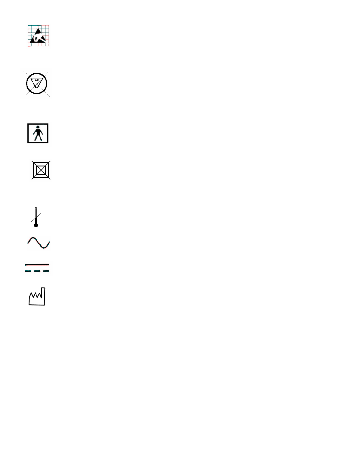
Caution: ESD sensitive
This symbol indicates that the equipment is not Category AP, and therefore must not
be used in the presence of flammable liquids or gasses.
.
Type BF patient applied part (B= body, F= floating applied part).
This symbol indicates that the equipment does not utilize a floating double insulated
isolation connection, and therefore must not be connected to external equipment that
is not protectively earthed (DO NOT connect to class II equipment).
Storage/Operating Temperature conditions
Alternating Current (AC)
Direct Current (DC)
Date of manufacture
Q00110 Rev A 8/06 Page 17 of 225
"Note: Copies are uncontrolled documents - For revision verification see the Master Docum e ntation List"
2 SAFETY
It is extremely important to read the following definitions of WARNING information, prior to
beginning any service on any sub-system within the z.one product. As you see applicability of
each of these noted WARNINGs, during the course of the servicing process, be prepared to avoid
harm to persons and equipment by proper adherence.
2.1 WARNINGs During Service/Operation
WARNING
To prevent possible damage to the electronics of the system from condensation, the following
warning must be observed:
WARNING
WARNING
WARNING
Anytime the
that differs greatly in temperature and/or humidity, from the environment where it has been
moved for intended operation, (as a result of shipping or transport) the unit should be allowed
to stand for a period of no less than 30 minutes
Inspect all cables and power cords BEFORE powering-on the
transducer. Do not use the system if visual signs of external damage are observed.
To achieve proper grounding reliability, the
fully inserted into a receptacle marked 'Hospital Grade". Do not remove the grounding wire.
If there is any question of power outlet or power cord integrity, do not proceed. Obtain
qualified technical assistance
The ZONARE
avoid electrical shock, the no covers should be removed except by ZONARE factory trained
personnel. Failure to do so may void the system warranty or service contract coverage
Warnings.
z.one
(Scan Engine, SuperCart or minCart) is being moved from an environment
, prior to inserting battery or powering on.
z.one
system; or connecting the
z.one
SuperCart or miniCart power plug must be
.
z.one
contains no operator-serviceable components within the enclosures. To
WARNING
Do not operate the
washed with flammable cleaning and disinfecting agents. Cleaners can produce explosive
vapors. Check labels of original containers of cleaners and disinfectants for warnings about
vapors. Thoroughly ventilate the room, if such vapors may potentially be present, prior to
activating any of the
Q00110 Rev A 8/06 Page 18 of 225
"Note: Copies are uncontrolled documents - For revision verification see the Master Docum e ntation List"
z.one
system in the presence of flammable anesthetics or in a room recently
z.one
components.
2.2 Battery WARNINGs
WARNINGS.
• The battery has a safe smart device. Do not disassemble or alter the battery in any
way.
• Charge the battery at room temperature.
• Do not short-circuit battery by directly connecting the positive and negative terminals
with metal objects.
• Do not heat or discard battery in a fire.
• Do not expose the battery to temperatures above 150 degree F.
• Do not charge the battery near a heat source
• Do not leave battery in direct sunlight
• Recharge battery only using Scan Engine in a docked condition in
miniCartt, or remotely using ZONARE Z.ONE battery charger.
• Do not use a damaged battery.
• Inspect the battery for damage before charging or placing the battery in the
• Do not connect battery to an electrical power outlet.
• Do not continue to recharge the battery if it does not recharge fully after 4 hours
• Battery MUST be REMOVED from Scan Engine, during shipping/transport of the
2.3 CAUTIONs During Service
CAUTIONS
• Apply proper line voltage. Verify that the
voltage of site receptacle. Also verify that all plugs match the receptacle type.
Mismatched voltage or plug configuration can damage system components.
• Protect the system from water or other liquids that could drip into the electronic
components.
• Do not drop the transducer(s), or allow them to impact any hard surfaces.
z.one
SuperCar or
z.one
system is compatible to match the AC
z.one
z.one
.
• Perform no unauthorized modification to any of the
modification can introduce additional hazards to the product.
z.one
sub-systems. Unauthorized
Q00110 Rev A 8/06 Page 19 of 225
"Note: Copies are uncontrolled documents - For revision verification see the Master Docum e ntation List"
2.4 Battery CAUTIONs
CAUTIONS
• To protect the battery from potential thermal damage, the system monitors the
temperature of the battery at all times. If the battery is detected as exceeding the
maximum safe operating temperature, a warning message will appear on the display of
the
z.one
• To prevent possible damage to the unit, the battery should be REMOVED from the
Scan Engine prior to transport or shipment.
• Do not immerse battery in water or allow it to get wet.
• Do not put the battery into a microwave oven or pressurized container.
• Use only batteries provided by ZONARE
• Store the battery between -20 to 60o Celsius (-4 o to 158
• If the battery leaks, emits orders, emits heat, is deformed or discolored in any way
immediately remove it and stop using it.
.
o
F).
2.5 USB Memory Stick CAUTIONs
CAUTIONS
• To prevent possible loss of patient image data or corruption to the removable USB
Memory Stick, should only be inserted or removed from the Scan Engine while the
z.one
is in a powered OFF state.
Q00110 Rev A 8/06 Page 20 of 225
"Note: Copies are uncontrolled documents - For revision verification see the Master Docum e ntation List"

3 SYSTEM SPECIFICATIONS
This section contains z.one system and accessory specifications. For information on the
specifications for ZONARE authorized peripherals, refer to the manufacturers’ documentation.
3.1 System Dimensions
SuperCart (with Scan Engine installed)
• Height:
- Max operational: 141 cm (55.6 in)
- Min operational: 129 cm (50.6 in)
- Display lowered for transport: 104 cm (41.1 in)
• Width: 61 cm (24.2 in)
• Depth: 85 cm (33.6 in)
• Weight: 82 kg (180 lb)
miniCart (with Scan Engine installed)
• Height:
- Max operational: 160 cm (63 in)
- Min operational: 134 cm (53 in)
- Display lowered for transport: 104 cm (41.5 in.)
• Width: 57.2 cm (22.5 in)
• Depth: 56.1 cm (22.0 in)
• Weight: 55 kg (132 lbs.)
Scan Engine
• Height: 7.3 cm (2.9 in)
• Width: 18.7 cm (7.4 in)
• Depth: 25 cm (9.8 in)
• Weight: 2.5 kg (5.6 lb) – with battery, no probe
3.2 Displays
SuperCart
• 13” high resolution color LCD display
• 640x480 display format
Q00110 Rev A 8/06 Page 21 of 225
"Note: Copies are uncontrolled documents - For revision verification see the Master Docum e ntation List"

• 0.41 mm pixel pitch
• Viewing angle (H/V): 170 degrees typical
• Minimum 10:1 contrast
o
• +/- 90
• 30
rotation
o
backward tilt
• Full 90o forward tilt into secure transport position
• Integrated Brightness/Contrast controls
• Advanced setup parameters via on-screen menu
miniCart
• 13” high resolution color LCD display
• 640x480 display format
• 0.41 mm pixel pitch
• Viewing angle (H/V): 170 degrees typical
• Minimum 10:1 contrast
• +/- 90o rotation
• 30o backward tilt
• Full 90o forward tilt into secure transport position
Scan Engine
• 5.8” high resolution color LCD display
• 800x480 display format
• 0.16 mm pitch
• Brightness and Contrast controls
3.3 Image Storage
Internal:
512MB Internal CompactFlash Memory (Standard)
• DICOM uncompressed: 1280 images
• DICOM RLE: 4060 images
• BMP: 1700 images
2GB Internal CompactFlash Memory (Option)
• DICOM uncompressed: 5000 images
• DICOM RLE: 15,900 images
• BMP: 6650 images
Q00110 Rev A 8/06 Page 22 of 225
"Note: Copies are uncontrolled documents - For revision verification see the Master Docum e ntation List"

3.4 Transducers
C5-2 Convex
• Primary Applications: Abdominal, OB/GYN
• Secondary Applications: Vascular,
• Bandwidth: 2-5MHz
• Number of Elements: 128
• Physical footprint: 20 x 64mm
• Convex Radius: 50mm
• Field of View: 65 degrees
• Harmonic Transmit Frequency: 3.0 and 4.0 MHz
• Biopsy Guide: Option
L10-5 Linear
• Primary Applications: Vascular, Small Parts, Breast
• Secondary Applications: OB/GYN, Pediatric, Intraoperative
• Bandwidth: 5-10MHz
• Number of Elements: 128
• Physical footprint: 11 x 43mm
• Field of View: 38mm
• Biopsy Guide: Option
L8-3 Linear
• Primary Applications: Peripheral Vascular
• Secondary Applications: Pediatric Hips, Difficult Small Parts
• Bandwidth: 3-8MHz
• Number of Elements: 128
• Physical footprint: 12 x 43mm
• Field of View: 38mm
• Biopsy Guide: Option
E9-4 Transvaginal
• Primary Applications: OB/GYN
• Bandwidth: 4-9MHz
• Number of Elements: 128
• Physical footprint: 20 x 26mm
• Convex Radius: 11.5mm
• Field of View: 135 degrees
• Biopsy Guide: Option (disposable)
P4-1 Phased
Q00110 Rev A 8/06 Page 23 of 225
"Note: Copies are uncontrolled documents - For revision verification see the Master Docum e ntation List"

• Primary Applications: Deep Abdominal, Abdominal Vascular, Trauma
• Secondary Applications: Obstetrics, Fetal Heart, Gynecology
• Bandwidth: 1-4MHz
• Number of Elements: 128
• Physical footprint: 16 x 31mm
• Field of View: 90 degrees
• Biopsy Guide: *Option *(to be released)
P10-4 Phased
• Primary Applications: Neonatal, Pediatric Head/Abdomen
• Secondary Applications: Vascular, Intraoperative
• Bandwidth: 4-10MHz
• Number of Elements: 128
• Physical footprint: 11 x 18mm
• Field of View: 90 degrees
• Biopsy Guide: *Option *(to be released)
3.5 Accessories
• 2-Bay Battery Charger
• AC Power Adapter
• USB Memory Stick
3.6 Peripherals
SuperCart:
• Sony UP-897MD B/W Video Printer
• Sony UP-21MD, Color Video Printer
• Panasonic LQ-MD800, DVD Recorder
miniCart:
• Sony UP-D897 Digital B/W Printer
3.7 Imaging Modalities
B-Mode
Live B-Mode (Only) Controls
• Depth – up to 30cm
• Frequency
• Tissue Harmonics
Q00110 Rev A 8/06 Page 24 of 225
"Note: Copies are uncontrolled documents - For revision verification see the Master Docum e ntation List"

• Acoustic Zoom
• Acoustic Output
• DUAL imaging mode
Live & Retrospective Imaging Controls
• Gain
• TGC
• Grayscale Map
• Dynamic Range
• Persistence
• Up/Down Invert
• Left/Right Invert
• Edge Enhance
M-Mode
Live M-Mode (Only) Controls
• Depth – up to 30cm
• Frequency
• Tissue Harmonics
• Cursor Position
• Acoustic Zoom
• Acoustic Output
Live & Retrospective Imaging Controls
• Gain
• TGC
• Sweep Speed
• Display Format (Two B reference image sizes and full screen strip)
• M Map
• M Dynamic Range
• Persistence
• Up/Down Invert
• Left/Right Invert
• Edge Enhancement
Color Doppler
Live CD (Only) Controls
• ROI Position
• ROI Size – up to full screen
• Velocity Scale
• Wall Filter
• Steering Angle
Q00110 Rev A 8/06 Page 25 of 225
"Note: Copies are uncontrolled documents - For revision verification see the Master Docum e ntation List"

• Acoustic Zoom
• Acoustic Output
• DUAL imaging mode
Live & Retrospective Imaging Controls
• Gain
• Color Map
• Baseline Shift
• Invert
• Persistence
Power Doppler
Live PD (Only) Controls
• ROI Position
• ROI Size – up to full screen
• Velocity Scale
• Wall Filter
• Steering Angle
• Acoustic Zoom
• Acoustic Output
• DUAL imaging mode
Live & Retrospective Imaging Controls
• Gain
• Power Doppler Map
• Persistence
PW (Pulsed Wave) Doppler
Live PW (Only) Controls
• Cursor Position
• Gate Size
• Steering Angle
• Velocity Scale
• Update
• Acoustic Zoom
• Acoustic Power
Live & Retrospective Imaging Controls
• Gain
• Angle Correct – manual
• Angle Correct – ‘Quick 60’
• Baseline Shift
Q00110 Rev A 8/06 Page 26 of 225
"Note: Copies are uncontrolled documents - For revision verification see the Master Docum e ntation List"

• Wall Filter
• Invert
• Display Format (Two B reference image sizes and full screen strip)
• Sweep Speed
• PW Map
• PW Dynamic Range
• Audio Volume
Imaging Mode Combinations
• B+CD/PD
• B+M
• B+PW (real-time duplex)
• B+CD/PD+PW (real-time Triplex)
• DUAL (side-by-side imaging)
• Acoustic zoom in all imaging modes
Imaging Formats
• Convex
• Linear
• Micro-convex
• Phased Array
3.8 Site Requirements
Power
• 100 – 120VAC, 50-60Hz or 200 – 240VAC, 50-60Hz (Factory Configurable)
Environmental
• Cooling consistent with 1024 BTU / hour system output (Scan Engine + SuperCart/miniCart)
• Ambient air temperature of 0 o – 35o Celsius (32 o - 95 o F)
• Ambient relative humidity of up to 80%, non-condensing
3.9 System Power
• Factory Configurable Input Voltage:
- 100 – 120V @ 6A (max)
- 200 – 240V @3A (max)
• Line Frequency: 50 – 60Hz
Q00110 Rev A 8/06 Page 27 of 225
"Note: Copies are uncontrolled documents - For revision verification see the Master Docum e ntation List"

• Power for peripherals: 300W
3.10 System Power Protection
• SuperCart
- Re-settable AC circuit breaker
• miniCart
- User-replaceable fuses:
− T6.3A/250V ..................................................... (100-120V Systems)
− T3.15A/250V ................................................... (200-240V Systems)
3.11 Electrical Specifications
DC Voltages:
• SuperCart DC Power Supplies
Voltage Purpose Max Current Rating
+12V
+12V
+5V
SuperCart Main Logic / Scan Engine Power 20 A
• miniCart DC Power Supplies
Voltage Purpose Max Current Rating
+12V
+12V
+5V
LCD Display Source Power 6 A
SuperCart +5V Logic Power
Scan Engine Power 20 A
LCD Display Source Power 6 A
USB Hub Power
8 A
8 A
Q00110 Rev A 8/06 Page 28 of 225
"Note: Copies are uncontrolled documents - For revision verification see the Master Docum e ntation List"

• Scan Engine Power Board DC Supplies
Voltage Purpose Total Current
+1.2V
+1.5V
+2.5V
+3.3V
Vfan
+5.0V
V5.0RTC
+12V
HV1
HV2
HV3
Digital FPGA (Digital Board)
Striker (Analog Board)
ADC’s and AFE’s
CPU, FPGA’s, etc. 2.5 A
Power Supply monitoring
Levels shifters, muxes, eeprom.
Local power for PIC, etc. 25 mA
Probe Mux Bias Power Transducer dependent
Transmit Power (Tissue) User variable
Transmit Power (Doppler) User variable
DSP Power 2.3 A
11.2 A
FPGA busses
ADC’s +1.8V
DDR SDRAM 0.30 A
Cooling fans 0.25A
Pulsers 170 mA
7.4 A
10 mA
• Battery
• Smart” pack, 4-cell, 11.25 VDC, 4.4 amp-hours, rechargeable lithium ion battery pack
• Operating range: (values listed are approximations)
- Active use......................................30-60 minutes (mode & display brightness
dependent)
- Standby mode................................2.0-3.0 hours
- Storage mode (in Scan Engine).....3 weeks
• Battery Charger, 2-Bay
• Models:
- Z311: Domestic Version...............110 VAC power cord
- Z312 : International Version .......220VAC power cord
• Operating Modes:
- CHARGE Mode ...........................1.0 hour (dependent current charge state)
- RECALIBRATE Mode................14 hours (discharge->charge->discharge-fully charge)
• Bays:
- Left Bay.........................................Recalibrate or Charge operation
- Right Bay.......................................Charge operation only
• AC Power Adapter (2.0 Scan Engine)
Q00110 Rev A 8/06 Page 29 of 225
"Note: Copies are uncontrolled documents - For revision verification see the Master Docum e ntation List"

• Models:
- Z316 : Domestic Version..............110 VAC power cord
- Z317 : International Version .......220 VAC power cord
• Voltage Output
- +9V to +12V..................................+/- 5% over loading
3.12 Temperature, Humidity, Pressure Limits
System: (During Operation):
• Temperature 0o to 35o Celsius | (32
o
to 95
o
F)
• Relative Humidity 15–80%
• Elevation 3,100 to (-116) Meters | 10,200 to (-1,250) Feet
System: (During Shipping/Storage): Battery MUST be REMOVED from Scan Engine!
• Temperature -20 to 60o Celsius | (-4 o to 158
o
F)
• Relative Humidity 15–90%
• Elevation 5,944 to (-116) Meters | 19,500 to (-1,250) Feet
3.13 Device Classification
• FDA Class II Device Classification
• CE / MDD Class IIa-rule 10 active device intended for diagnosis
3.14 Safety Standards
All ZONARE instruments, cables, and diagnostic ultrasound imaging transducers have been designed
to meet the essential requirements contained in:
• 93/42/EEC (Medical Device Directive).
In addition, all the above listed equipment meets the following appropriate requirements:
• UL 2601-1 (Standard for Medical Electrical Equipment Part 1: General Requirements for
Safety)
Q00110 Rev A 8/06 Page 30 of 225
"Note: Copies are uncontrolled documents - For revision verification see the Master Docum e ntation List"
 Loading...