

Page 1
Z.ONE
ZONARE, the ZONARE logo and z.zone, Convertible Ultrasound™, Zone Sonography™, and Channel
Domaine™ are all trademarks of ZONARE Medical Systems Inc. All other trademarks are the pr operty of
their respective holders.
Z.ONE ULTRASOUND SYSTEM : (2.0)
OPERATOR MANUAL
premium compact performance
Zone Sonography Technology
Z.ONE
ZONARE • i
• i
Page 2

ZONARE, the ZONARE logo and z.one, Convertible Ultrasound™, Zone Sonography™, and Channel
Domain™ are all trademarks of ZONARE Medical Systems Inc. All other trademarks are the property of
their respective holders.
z.one Convertible Ultrasound™ System is covered by one or more of the following Patents:
The
6,251,073; 6,569,102; 6,866,631; 6,618,206; 6,773,399; 6,663,567; 6,685,645; 6,733,455; 6,866,632
United States Federal Law restricts this device to sale by or on the order of a physician, licensed
by the law of the jurisdiction in which they practice, to use or order the use of this device.
Part Number Q00108
Rev.A, Software Revision 2.0, August 2006
© 2006 by ZONARE Medical Systems Inc.
All rights reserved. Printed in the USA.
ii • z.one OPERATOR MANUAL, Version 2.0 ZONARE
ii •
Page 3

Contents
Contents
List of Figures . . . . . . . . . . . . . . . . . . . . . . . . . . . . . . . . ix
1 Introduction to the ZONARE z.one . . . . . . . . . . . . . . . . 1-1
Intended Use. . . . . . . . . . . . . . . . . . . . . . . . . . . . . . . . . . . . 1-2
z.one Components. . . . . . . . . . . . . . . . . . . . . . . . . . . . . . . . . 1-3
SuperCart . . . . . . . . . . . . . . . . . . . . . . . . . . . . . . . . . . . 1-3
miniCart . . . . . . . . . . . . . . . . . . . . . . . . . . . . . . . . . . . . 1-8
Scan Engine . . . . . . . . . . . . . . . . . . . . . . . . . . . . . . . . . 1-13
USB Memory Sticks. . . . . . . . . . . . . . . . . . . . . . . . . . . . . 1-16
Transducers . . . . . . . . . . . . . . . . . . . . . . . . . . . . . . . . . 1-16
SuperCart Peripherals . . . . . . . . . . . . . . . . . . . . . . . . . . . 1-18
miniCart Peripherals . . . . . . . . . . . . . . . . . . . . . . . . . . . . 1-18
DICOM Connectivity . . . . . . . . . . . . . . . . . . . . . . . . . . . . . . 1-18
Contact and System Information . . . . . . . . . . . . . . . . . . . . . . . 1-18
2 Getting Started . . . . . . . . . . . . . . . . . . . . . . . . . . . . . . . 2-1
SuperCart & miniCart Moving Cautions . . . . . . . . . . . . . . . . . . . . 2-1
Introduction . . . . . . . . . . . . . . . . . . . . . . . . . . . . . . . . . . 2-1
Security Locking of the Scan Engine . . . . . . . . . . . . . . . . . . . . . . 2-4
Docking and Undocking the Scan Engine . . . . . . . . . . . . . . . . . . . 2-4
Powering On and Off . . . . . . . . . . . . . . . . . . . . . . . . . . . . . . . 2-7
Inserting and Removing USB Memory Stick Media. . . . . . . . . . . . . 2-11
Installing and Removing a Battery . . . . . . . . . . . . . . . . . . . . . . 2-12
Checking Battery Charge. . . . . . . . . . . . . . . . . . . . . . . . . . 2-13
Battery Charger, 2-Bay: Connection & Use . . . . . . . . . . . . . . . . . . 2-14
AC Power Adapter: Connection & Use . . . . . . . . . . . . . . . . . . . . 2-17
Connecting and Disconnecting a Transducer. . . . . . . . . . . . . . . . . 2-19
Applying a Transducer Cover . . . . . . . . . . . . . . . . . . . . . . . . . 2-20
Attaching a Biopsy Guide . . . . . . . . . . . . . . . . . . . . . . . . . . . 2-20
Mechanical Controls . . . . . . . . . . . . . . . . . . . . . . . . . . . . . . 2-21
ZONARE z.one OPERATOR MANUAL, Version 2.0 • iii
• iii
Page 4

Contents
miniCart Enhanced Keyboard Access . . . . . . . . . . . . . . . . . . . . . 2-24
SuperCart Rear I/O Panel. . . . . . . . . . . . . . . . . . . . . . . . . . . . 2-24
miniCart Rear I/O Panel . . . . . . . . . . . . . . . . . . . . . . . . . . . . 2-25
User Controls. . . . . . . . . . . . . . . . . . . . . . . . . . . . . . . . . . . 2-26
SuperCart User Interface Functions . . . . . . . . . . . . . . . . . . . . 2-26
SuperCart Keyboard Functions . . . . . . . . . . . . . . . . . . . . . . 2-30
miniCart Enhanced Keyboard Functions . . . . . . . . . . . . . . . . . 2-33
Scan Engine User Interface Functions. . . . . . . . . . . . . . . . . . . 2-36
Menus . . . . . . . . . . . . . . . . . . . . . . . . . . . . . . . . . . . . . . . 2-38
Tabs . . . . . . . . . . . . . . . . . . . . . . . . . . . . . . . . . . . . . . 2-40
3 Imaging . . . . . . . . . . . . . . . . . . . . . . . . . . . . . . . . . . . . 3-1
Preparation for Imaging. . . . . . . . . . . . . . . . . . . . . . . . . . . . . 3-1
Patient Information Form. . . . . . . . . . . . . . . . . . . . . . . . . . 3-1
DICOM Worklist. . . . . . . . . . . . . . . . . . . . . . . . . . . . . . . 3-4
Beginning a New Exam. . . . . . . . . . . . . . . . . . . . . . . . . . . 3-4
Presets . . . . . . . . . . . . . . . . . . . . . . . . . . . . . . . . . . . . 3-6
Function Keys . . . . . . . . . . . . . . . . . . . . . . . . . . . . . . . . 3-10
Live and Frozen Images . . . . . . . . . . . . . . . . . . . . . . . . . . 3-11
Brightness Mode (B-mode) Imaging . . . . . . . . . . . . . . . . . . . . . . 3-11
B-mode Menu - (SuperCart & Scan Engine) . . . . . . . . . . . . . . . 3-12
B-Mode Touchscreen Menu - (miniCart) . . . . . . . . . . . . . . . . . 3-12
Working with B-mode Imaging . . . . . . . . . . . . . . . . . . . . . . 3-13
“DUAL” Imaging Mode - Introduction . . . . . . . . . . . . . . . . . . 3-13
“DUAL” Imaging Mode - Activation . . . . . . . . . . . . . . . . . . . 3-13
Simultaneous DUAL Operation . . . . . . . . . . . . . . . . . . . . . . 3-14
Optimize Feature . . . . . . . . . . . . . . . . . . . . . . . . . . . . . . 3-14
B-mode Controls. . . . . . . . . . . . . . . . . . . . . . . . . . . . . . . 3-16
Motion Mode (M-Mode) Imaging . . . . . . . . . . . . . . . . . . . . . . . 3-22
M-Mode Menu. . . . . . . . . . . . . . . . . . . . . . . . . . . . . . . . 3-23
Working with M-mode Imaging . . . . . . . . . . . . . . . . . . . . . . 3-23
M-mode Controls . . . . . . . . . . . . . . . . . . . . . . . . . . . . . . 3-24
Color and Power Doppler Imaging . . . . . . . . . . . . . . . . . . . . . . 3-27
Color Doppler Menu (SuperCart & Scan Engine) . . . . . . . . . . . . 3-28
Color Doppler Touchscreen Menu - (miniCart) . . . . . . . . . . . . . 3-28
Working with Color and Power Doppler Imaging. . . . . . . . . . . . 3-29
“DUAL” Imaging Mode - Introduction . . . . . . . . . . . . . . . . . . 3-29
“DUAL” Imaging Mode - Activation . . . . . . . . . . . . . . . . . . . 3-30
Simultaneous DUAL Operation . . . . . . . . . . . . . . . . . . . . . . 3-30
iv • z.one OPERATOR MANUAL, Version 2.0 ZONARE
iv •
Page 5

Contents
Color Doppler and Power Doppler Controls . . . . . . . . . . . . . . 3-32
Pulse Wave (PW) Doppler Imaging . . . . . . . . . . . . . . . . . . . . . . 3-38
Working with PW Doppler Imaging . . . . . . . . . . . . . . . . . . . 3-38
PW Doppler Controls. . . . . . . . . . . . . . . . . . . . . . . . . . . . 3-40
Duplex Mode. . . . . . . . . . . . . . . . . . . . . . . . . . . . . . . . . . . 3-45
Triplex Mode . . . . . . . . . . . . . . . . . . . . . . . . . . . . . . . . . . . 3-46
4 Annotations. . . . . . . . . . . . . . . . . . . . . . . . . . . . . . . . . . 4-1
Annotation Types . . . . . . . . . . . . . . . . . . . . . . . . . . . . . . . . . 4-2
Free-form Text . . . . . . . . . . . . . . . . . . . . . . . . . . . . . . . . . 4-2
Programmed Orientation Text (POT) . . . . . . . . . . . . . . . . . . . . 4-2
List Text Entries . . . . . . . . . . . . . . . . . . . . . . . . . . . . . . . . 4-2
Arrow Graphic . . . . . . . . . . . . . . . . . . . . . . . . . . . . . . . . 4-3
Body Pattern Graphics . . . . . . . . . . . . . . . . . . . . . . . . . . . . 4-3
Annotation Procedures . . . . . . . . . . . . . . . . . . . . . . . . . . . . . . 4-3
Working with Annotations. . . . . . . . . . . . . . . . . . . . . . . . . . 4-7
Working with Graphics. . . . . . . . . . . . . . . . . . . . . . . . . . . . 4-9
5 Measurements and Calculations . . . . . . . . . . . . . . . . . . 5-1
Introduction to Measurements and Calculations . . . . . . . . . . . . . . . 5-1
Exam Types and Measurement Menus . . . . . . . . . . . . . . . . . . . 5-2
Calculation Packages . . . . . . . . . . . . . . . . . . . . . . . . . . . . . 5-2
Tools for Measurements and Calculations . . . . . . . . . . . . . . . . . . . 5-5
Freeze Menu. . . . . . . . . . . . . . . . . . . . . . . . . . . . . . . . . . 5-5
Measure Menu . . . . . . . . . . . . . . . . . . . . . . . . . . . . . . . . 5-5
Calipers . . . . . . . . . . . . . . . . . . . . . . . . . . . . . . . . . . . . 5-6
Data Display Box (DDB) . . . . . . . . . . . . . . . . . . . . . . . . . . . 5-7
Generic Measurements Procedures . . . . . . . . . . . . . . . . . . . . . . . 5-7
B-Mode. . . . . . . . . . . . . . . . . . . . . . . . . . . . . . . . . . . . . 5-7
M-Mode . . . . . . . . . . . . . . . . . . . . . . . . . . . . . . . . . . . 5-11
PW Doppler Mode . . . . . . . . . . . . . . . . . . . . . . . . . . . . . 5-12
OB Calculation Package . . . . . . . . . . . . . . . . . . . . . . . . . . . . 5-20
OB Worksheets and Reports . . . . . . . . . . . . . . . . . . . . . . . . 5-22
Procedures for OB Calculation Packages. . . . . . . . . . . . . . . . . 5-24
Additional Calculation Packages . . . . . . . . . . . . . . . . . . . . . . . 5-26
Gyn and Follicular Package . . . . . . . . . . . . . . . . . . . . . . . . 5-26
Vascular Packages. . . . . . . . . . . . . . . . . . . . . . . . . . . . . . 5-26
Carotid Calc Package . . . . . . . . . . . . . . . . . . . . . . . . . . . 5-26
ZONARE z.one OPERATOR MANUAL, Version 2.0 • v
• v
Page 6

Contents
Upper Extremity Arterial Calc Package . . . . . . . . . . . . . . . . . 5-27
Lower Extremity Arterial Calc Package . . . . . . . . . . . . . . . . . 5-27
Lower Extremity Venous Calc Package . . . . . . . . . . . . . . . . . . 5-28
Upper Extremity Venous Calc Package . . . . . . . . . . . . . . . . . . 5-28
Worksheet and Report Pages . . . . . . . . . . . . . . . . . . . . . . . . . . 5-29
z.one Measurement Accuracy . . . . . . . . . . . . . . . . . . . . . . . . . 5-30
2D Measurement Accuracy. . . . . . . . . . . . . . . . . . . . . . . . . 5-30
Elapsed Time or Rate Measurement Accuracy . . . . . . . . . . . . . . 5-31
Color Doppler Registration Accuracy. . . . . . . . . . . . . . . . . . . 5-32
PW Doppler Velocity Measurement Accuracy . . . . . . . . . . . . . . 5-32
Numeric Display Accuracy. . . . . . . . . . . . . . . . . . . . . . . . . 5-33
6 Archive and Review . . . . . . . . . . . . . . . . . . . . . . . . . . . 6-1
Tools for Archive and Review . . . . . . . . . . . . . . . . . . . . . . . . . 6-2
“Media” Configuration - Compression Settings:. . . . . . . . . . . . . 6-2
“Media” Configuration - (Clip Store) Duration Setting:. . . . . . . . . 6-2
“Storage Media”: Tools - Maintenance: . . . . . . . . . . . . . . . . . . 6-3
Store/Print Keys: Paper Printing (B/W or Color) to Sony Printers . . 6-3
Store/Print Keys: Still Image & Clip Image Stores. . . . . . . . . . . . 6-6
Keyboard Keys (SuperCart & miniCart) . . . . . . . . . . . . . . . . . 6-8
Archive and Review Menu Items . . . . . . . . . . . . . . . . . . . . . 6-9
Viewing Images in an Archived Exam . . . . . . . . . . . . . . . . . . 6-14
Deleting Images and Exams . . . . . . . . . . . . . . . . . . . . . . . . 6-15
Storing Archived Exams to DICOM Devices (SuperCart or miniCart) 6-20
Restarting an Exam . . . . . . . . . . . . . . . . . . . . . . . . . . . . . 6-20
Importing/Exporting of Exams: USB Memory Sticks . . . . . . . . . . 6-22
7 Peripherals . . . . . . . . . . . . . . . . . . . . . . . . . . . . . . . . . . 7-1
Sony UP-897MD B&W Video Printer . . . . . . . . . . . . . . . . . . . . . 7-2
Setup: . . . . . . . . . . . . . . . . . . . . . . . . . . . . . . . . . . . . . 7-2
Operation: . . . . . . . . . . . . . . . . . . . . . . . . . . . . . . . . . . 7-2
Sony UP-21MD Color Video Printer.. . . . . . . . . . . . . . . . . . . . . . 7-3
Operation: . . . . . . . . . . . . . . . . . . . . . . . . . . . . . . . . . . 7-3
Panasonic LQ-MD800 DVD Video Recorder . . . . . . . . . . . . . . . . . 7-4
Recording: . . . . . . . . . . . . . . . . . . . . . . . . . . . . . . . . . . 7-4
Finalizing (Burning) DVD For Viewing: . . . . . . . . . . . . . . . . . 7-4
Sony UP-D897 Digital (USB 2.0) B&W Printer (miniCart). . . . . . . . . . 7-5
Operation: . . . . . . . . . . . . . . . . . . . . . . . . . . . . . . . . . . 7-6
vi • z.one OPERATOR MANUAL, Version 2.0 ZONARE
vi •
Page 7

Contents
8 DICOM Connectivity. . . . . . . . . . . . . . . . . . . . . . . . . . . . 8-1
Configuring DICOM . . . . . . . . . . . . . . . . . . . . . . . . . . . . . . . 8-1
DICOM menu . . . . . . . . . . . . . . . . . . . . . . . . . . . . . . . . . 8-2
DICOM Configuration Parameters . . . . . . . . . . . . . . . . . . . . . 8-3
DICOM Pre-Installation Survey Form . . . . . . . . . . . . . . . . . . . 8-6
9 Safety. . . . . . . . . . . . . . . . . . . . . . . . . . . . . . . . . . . . . . . 9-1
Introduction . . . . . . . . . . . . . . . . . . . . . . . . . . . . . . . . . . . . 9-1
Symbols. . . . . . . . . . . . . . . . . . . . . . . . . . . . . . . . . . . . . . . 9-1
Regulatory Information. . . . . . . . . . . . . . . . . . . . . . . . . . . . . . 9-3
Device Classification . . . . . . . . . . . . . . . . . . . . . . . . . . . . . 9-3
Safety Standards . . . . . . . . . . . . . . . . . . . . . . . . . . . . . . . 9-3
Warnings and Cautions . . . . . . . . . . . . . . . . . . . . . . . . . . . 9-3
Electrical Safety . . . . . . . . . . . . . . . . . . . . . . . . . . . . . . . . 9-8
Medical Ultrasound Safety . . . . . . . . . . . . . . . . . . . . . . . . . . . . 9-9
Acoustic Output. . . . . . . . . . . . . . . . . . . . . . . . . . . . . . . . 9-9
General Controls . . . . . . . . . . . . . . . . . . . . . . . . . . . . . . 9-11
B-Mode Controls . . . . . . . . . . . . . . . . . . . . . . . . . . . . . . 9-12
Color Doppler Controls . . . . . . . . . . . . . . . . . . . . . . . . . . 9-12
Transducers: Performance (Measured) . . . . . . . . . . . . . . . . . . 9-13
Transducers: Acoustic Power Output. . . . . . . . . . . . . . . . . . . 9-15
Display Accuracy and Precision. . . . . . . . . . . . . . . . . . . . . . 9-47
Guidance Documents. . . . . . . . . . . . . . . . . . . . . . . . . . . . 9-48
Product Labeling . . . . . . . . . . . . . . . . . . . . . . . . . . . . . . . . 9-50
10 User Maintenance . . . . . . . . . . . . . . . . . . . . . . . . . . . . 10-1
Touchscreen Calibration (Scan Engine) . . . . . . . . . . . . . . . . . . . . 10-3
PRESETS - SYSTEM: Backup/Restore. . . . . . . . . . . . . . . . . . . . . 10-4
Backing-Up System/Presets . . . . . . . . . . . . . . . . . . . . . . . . 10-4
Restoring System/Presets . . . . . . . . . . . . . . . . . . . . . . . . . 10-5
Software Upgrade/Installation Procedure . . . . . . . . . . . . . . . . . . 10-6
User Diagnostic Panel Menu: Operations. . . . . . . . . . . . . . . . . . . 10-8
Introduction . . . . . . . . . . . . . . . . . . . . . . . . . . . . . . . . . 10-8
Main AC Power Fuse Replacement (miniCart). . . . . . . . . . . . . . . 10-10
Basic System Care . . . . . . . . . . . . . . . . . . . . . . . . . . . . . . . 10-11
Checking the Battery . . . . . . . . . . . . . . . . . . . . . . . . . . . 10-11
Battery Charging . . . . . . . . . . . . . . . . . . . . . . . . . . . . . 10-11
ZONARE z.one OPERATOR MANUAL, Version 2.0 • vii
• vii
Page 8

Contents
Battery Maintenance . . . . . . . . . . . . . . . . . . . . . . . . . . . 10-12
Cleaning the z.one. . . . . . . . . . . . . . . . . . . . . . . . . . . . . 10-12
Cleaning and Care of Transducers . . . . . . . . . . . . . . . . . . . . . . 10-16
Cleaning and Disinfecting . . . . . . . . . . . . . . . . . . . . . . . . 10-16
Shipping and Storage . . . . . . . . . . . . . . . . . . . . . . . . . . . . . 10-19
Disposal. . . . . . . . . . . . . . . . . . . . . . . . . . . . . . . . . . . 10-19
11 Troubleshooting. . . . . . . . . . . . . . . . . . . . . . . . . . . . . . 11-1
Contact Information for ZONARE Service and Technical Support. . . . . 11-1
United States and Canada . . . . . . . . . . . . . . . . . . . . . . . . . 11-1
Europe and Asia. . . . . . . . . . . . . . . . . . . . . . . . . . . . . . . 11-1
User Troubleshooting Procedures . . . . . . . . . . . . . . . . . . . . . . . 11-2
Power-On Problems. . . . . . . . . . . . . . . . . . . . . . . . . . . . . 11-2
System Start-Up Problems . . . . . . . . . . . . . . . . . . . . . . . . . 11-3
Peripheral Problems. . . . . . . . . . . . . . . . . . . . . . . . . . . . . 11-3
Transducer Problems . . . . . . . . . . . . . . . . . . . . . . . . . . . . 11-4
Imaging Problems . . . . . . . . . . . . . . . . . . . . . . . . . . . . . . 11-4
General Operation Problems. . . . . . . . . . . . . . . . . . . . . . . . 11-5
12 Specifications . . . . . . . . . . . . . . . . . . . . . . . . . . . . . . . 12-1
EMC Standards Compliance . . . . . . . . . . . . . . . . . . . . . . . . 12-4
Electro-Medical Compliance . . . . . . . . . . . . . . . . . . . . . . . . 12-4
A Glossary . . . . . . . . . . . . . . . . . . . . . . . . . . . . . . . . . . . . A-1
Glossary. . . . . . . . . . . . . . . . . . . . . . . . . . . . . . . . . . . . . . A-1
Terms . . . . . . . . . . . . . . . . . . . . . . . . . . . . . . . . . . . . . A-1
Acronyms . . . . . . . . . . . . . . . . . . . . . . . . . . . . . . . . . . . . . A-5
viii • z.one OPERATOR MANUAL, Version 2.0 ZONARE
viii •
Page 9

List of Figures
List of Figures
Figure 1-1. SuperCart with Scan Engine Docked (Front View) . . . . . . 1-3
Figure 1-2. SuperCart with Scan Engine Docked (Back View). . . . . . . 1-4
Figure 1-3. SuperCart LCD Display . . . . . . . . . . . . . . . . . . . . . 1-5
Figure 1-4. SuperCart Control Panel: Overview . . . . . . . . . . . . . . 1-6
Figure 1-5. miniCart with Scan Engine Docked (Front View) . . . . . . . 1-8
Figure 1-6. miniCart LCD Display . . . . . . . . . . . . . . . . . . . . . . 1-9
Figure 1-7. miniCart Scan Engine Display Backstop . . . . . . . . . . . 1-10
Figure 1-8. miniCart Enhanced Keyboard & Scan Engine Controls:
Overview 1-11
Figure 1-9. Scan Engine with Transducer (Front View) . . . . . . . . . 1-13
Figure 1-10. Scan Engine (Back View) . . . . . . . . . . . . . . . . . . . . 1-14
Figure 1-11. Scan Engine LCD Display Layout. . . . . . . . . . . . . . . 1-15
Figure 1-12. USB Memory Sticks. . . . . . . . . . . . . . . . . . . . . . . 1-16
Figure 1-13. Transducer . . . . . . . . . . . . . . . . . . . . . . . . . . . . 1-16
Figure 2-1. Height Release Lever Positioning (SuperCart & miniCart). . 2-1
Figure 2-2. LCD Display Position. . . . . . . . . . . . . . . . . . . . . . . 2-2
Figure 2-3. Do’s for Transducer Cables . . . . . . . . . . . . . . . . . . . 2-2
Figure 2-4. User Position During Normal Cart Movement . . . . . . . . 2-3
Figure 2-5. Cart Wheel Position over Obstacles. . . . . . . . . . . . . . . 2-3
Figure 2-6. User Position During Cart Movement over Obstacles . . . . 2-3
Figure 2-7. Scan Engine Security “Locking” in SuperCart or miniCart. . 2-4
Figure 2-8. Scan Engine Docking in SuperCart . . . . . . . . . . . . . . . 2-5
Figure 2-9. Scan Engine Docking in miniCart. . . . . . . . . . . . . . . . 2-6
Figure 2-10. Scan Engine Undocking from miniCart . . . . . . . . . . . . 2-7
Figure 2-11. Scan Engine Power Button and SuperCart Circuit Breaker. . 2-8
Figure 2-12. ZONARE Start-up Screen . . . . . . . . . . . . . . . . . . . . 2-8
Figure 2-13. Access Control Screen . . . . . . . . . . . . . . . . . . . . . . 2-9
Figure 2-14. Scan Engine Power Button. . . . . . . . . . . . . . . . . . . 2-10
Figure 2-15. USB Memory Stick and Scan Engine (Rear View) . . . . . . 2-11
ZONARE z.one OPERATOR MANUAL, Version 2.0 • ix
• ix
Page 10

List of Figures
Figure 2-16. z.one Battery . . . . . . . . . . . . . . . . . . . . . . . . . . . 2-12
Figure 2-17. Battery Charger, 2-Bay . . . . . . . . . . . . . . . . . . . . . 2-14
Figure 2-18. LED Status Indicator Definitions . . . . . . . . . . . . . . . 2-16
Figure 2-19. AC Power Adapter - 2.0 Scan Engine . . . . . . . . . . . . . 2-17
Figure 2-20. z.one Transducer. . . . . . . . . . . . . . . . . . . . . . . . . 2-19
Figure 2-21. Brake Pedal (SuperCart) . . . . . . . . . . . . . . . . . . . . 2-21
Figure 2-22. Brake Levers (miniCart). . . . . . . . . . . . . . . . . . . . . 2-22
Figure 2-23. Height Adjustment Release Lever . . . . . . . . . . . . . . . 2-22
Figure 2-24. LCD Display Positioning (SuperCart). . . . . . . . . . . . . 2-23
Figure 2-25. LCD Display Rotation & Locking (miniCart). . . . . . . . . 2-23
Figure 2-26. miniCart Enhanced Keyboard Access. . . . . . . . . . . . . 2-24
Figure 2-27. SuperCart Rear I/O Panel . . . . . . . . . . . . . . . . . . . 2-24
Figure 2-28. miniCart Rear I/O Panel (USB Hub) . . . . . . . . . . . . . 2-25
Figure 2-29. SuperCart User Interface Layout. . . . . . . . . . . . . . . . 2-26
Figure 2-30. SuperCart Keyboard Layout . . . . . . . . . . . . . . . . . . 2-30
Figure 2-31. miniCart Enhanced Keyboard Layout. . . . . . . . . . . . . 2-33
Figure 2-32. Scan Engine User Interface Layout . . . . . . . . . . . . . . 2-36
Figure 2-33. Imaging Tab Menu with Selections . . . . . . . . . . . . . . 2-38
Figure 2-34. Presets Menu Tab with Selections . . . . . . . . . . . . . . . 2-40
Figure 2-35. Patients Menu Tab with Selections. . . . . . . . . . . . . . . 2-41
Figure 3-1. Patient Information Form with Exam Type Selection List. . 3-1
Figure 3-2. DICOM Worklist. . . . . . . . . . . . . . . . . . . . . . . . . 3-4
Figure 3-3. Function Key Configuration Screen . . . . . . . . . . . . . . 3-10
Figure 3-4. B-mode Image Display Format. . . . . . . . . . . . . . . . . 3-11
Figure 3-5. B-Mode Menu (Imaging Tab) - SuperCart & Scan Engine. . 3-12
Figure 3-6. B-Mode Touchscreen Menu - miniCart . . . . . . . . . . . . 3-12
Figure 3-7. M-Mode Image Display Format . . . . . . . . . . . . . . . . 3-22
Figure 3-8. M-Mode Menu (Imaging Tab) - SuperCart & Scan Engine . 3-23
Figure 3-9. Color Mode & Power Doppler Display Format . . . . . . . 3-27
Figure 3-10. Color Doppler Menu (Imaging Tab) - SuperCart & Scan Engine
3-28
Figure 3-11. Color Doppler Touchscreen Menu - miniCart . . . . . . . . 3-28
Figure 3-12. Pulse Wave (PW) Doppler Image . . . . . . . . . . . . . . . 3-38
Figure 4-1. Annotation Keys. . . . . . . . . . . . . . . . . . . . . . . . . 4-1
x • z.one OPERATOR MANUAL, Version 2.0 ZONARE
x•
Page 11

List of Figures
Figure 4-2. Top Row of the Keyboard (SuperCart or miniCart) Keys. . . 4-1
Figure 4-3. Text Menu & Virtual Keyboard (Scan Engine). . . . . . . . . 4-2
Figure 5-1. Calculation menus . . . . . . . . . . . . . . . . . . . . . . . . 5-2
Figure 5-2. Freeze Menu on the Scan Engine . . . . . . . . . . . . . . . . 5-5
Figure 5-3. Measure Menu. . . . . . . . . . . . . . . . . . . . . . . . . . . 5-5
Figure 5-4. Calculations Menu . . . . . . . . . . . . . . . . . . . . . . . 5-20
Figure 5-5. OB Worksheet (page 1) . . . . . . . . . . . . . . . . . . . . . 5-22
Figure 5-6. OB Worksheet (page 2) . . . . . . . . . . . . . . . . . . . . . 5-22
Figure 5-7. OB Worksheet (page 3) . . . . . . . . . . . . . . . . . . . . . 5-23
Figure 5-8. OB Worksheet (page 4) . . . . . . . . . . . . . . . . . . . . . 5-23
Figure 5-9. OB Report . . . . . . . . . . . . . . . . . . . . . . . . . . . . 5-24
Figure 6-1. Storage Media Configuration Menu . . . . . . . . . . . . . . 6-3
Figure 6-2. DICOM Print/Store Button Configuration Menu. . . . . . . 6-4
Figure 6-3. Internal CompactFlash Icon Active and Inactive . . . . . . . 6-6
Figure 6-4. SuperCart & miniCart Keyboard Keys . . . . . . . . . . . . . 6-8
Figure 6-5. Archive/Review keys . . . . . . . . . . . . . . . . . . . . . . 6-9
Figure 6-6. Patient Selection Table . . . . . . . . . . . . . . . . . . . . . 6-12
Figure 6-7. Exam Selection Table Heading Configuration . . . . . . . . 6-12
Figure 6-8. ARCHIVE Main Menu (EXPORT - IMPORT Option). . . . 6-22
Figure 6-9. EXPORT Main Menu . . . . . . . . . . . . . . . . . . . . . . 6-23
Figure 6-10. EXPORT “Options” Menu . . . . . . . . . . . . . . . . . . . 6-24
Figure 6-11. ARCHIVE Main Menu (EXPORT - IMPORT Option). . . . 6-25
Figure 6-12. IMPORT Main Menu . . . . . . . . . . . . . . . . . . . . . . 6-26
Figure 7-1. Sony UP-897MD B/W Video Printer . . . . . . . . . . . . . . 7-2
Figure 7-2. Sony UP-21MD Color Video Printer . . . . . . . . . . . . . . 7-3
Figure 7-3. Panasonic LQ-MD800 DVD Video Recorder. . . . . . . . . . 7-4
Figure 7-4. Sony UP-D897 B&W USB Printer . . . . . . . . . . . . . . . . 7-5
Figure 8-1. Network Icon Active and Inactive . . . . . . . . . . . . . . . 8-2
Figure 8-2. DICOM Menu . . . . . . . . . . . . . . . . . . . . . . . . . . . 8-2
Figure 8-3. NETWORK Configuration Screen. . . . . . . . . . . . . . . 8-10
Figure 8-4. DICOM General Configuration Screen . . . . . . . . . . . . 8-11
Figure 8-5. DICOM Network Storage Administration Screen. . . . . . 8-11
Figure 8-6. DICOM Network Storage New/Edit Screen. . . . . . . . . 8-12
Figure 8-7. DICOM MPPS Administration Screen . . . . . . . . . . . . 8-13
ZONARE z.one OPERATOR MANUAL, Version 2.0 • xi
• xi
Page 12

List of Figures
Figure 8-8. DICOM MPPS Manager New/Edit Screen . . . . . . . . . . 8-14
Figure 8-9. DICOM Printer Administration Screen . . . . . . . . . . . . 8-15
Figure 8-10. Printer New/Edit Screen . . . . . . . . . . . . . . . . . . . . 8-15
Figure 8-11. DICOM Worklist Configuration . . . . . . . . . . . . . . . . 8-17
Figure 8-12. DICOM Print/Store Buttons Configuration Screen . . . . . 8-18
Figure 9-1. The z.one Scan Engine- Model/Serial No. (with appropriate
SN/PN entries) 9-50
Figure 9-2. z.one Battery - Model/Serial No.(with appropriate SN/PN
entries) 9-50
Figure 9-3. 100-120V SuperCart Rear Panel - Model/Serial No. (with
appropriate SN/PN entries) 9-50
Figure 9-6. 200-240V SuperCart Backpack Outlet Strip Label . . . . . . 9-51
Figure 9-4. 200-240V SuperCart Rear Panel - Model/Serial No. (with
appropriate SN/PN entries) 9-51
Figure 9-5. 100-120V SuperCart Backpack Outlet Strip Label . . . . . . 9-51
Figure 9-7. miniCart Rear Panel - Model/Serial No. (with appropriate SN/
PN entries) 9-52
Figure 9-8. Linear Array Transducer Labels (with appropriate SN/PN
entries) 9-52
Figure 9-9. Curved Array Transducer Labels (with appropriate SN/PN
entries) 9-52
Figure 9-10. EV Transducer Labels (with appropriate SN/PN entries) . 9-53
Figure 9-11. Phased Transducer Labels (with appropriate SN/PN entries) 9-
53
Figure 9-12. AC Power Adapter Label (with appropriate SN/PN entries) 9-
53
Figure 9-13. AC Battery Adapter Power Supply Label. . . . . . . . . . . 9-53
Figure 10-1. Touchscreen Calibration Screen . . . . . . . . . . . . . . . . 10-3
Figure 10-2. Power on the Scan Engine . . . . . . . . . . . . . . . . . . . 10-7
Figure 10-3. Insert USB Memory Stick . . . . . . . . . . . . . . . . . . . . 10-7
Figure 10-4. User Diagnostic Panel. . . . . . . . . . . . . . . . . . . . . . 10-9
Figure 10-5. miniCart Main AC Fuse Replacement. . . . . . . . . . . . 10-10
Figure 10-6. Immersion Level Limits. . . . . . . . . . . . . . . . . . . . 10-17
xii • z.one OPERATOR MANUAL, Version 2.0 ZONARE
xii •
Page 13

Introduction to the ZONARE z.one
1
1
Introduction to the
ZONARE
The ZONARE z.one is the world’s first Convertible Ultrasound™ system,
easily converting from a full-featured SuperCart (or miniCart) to a portable
Scan Engine. This flexibility gives the clinician a software-controlled alldigital ultrasound system using Zone Sonography
The z.one acquires and displays Brightness Mode (B-mode), Motion Mode
(M-mode), Color Doppler, Power Doppler, and Pulsed Wave (PW) Doppler
diagnostic images. Features include Sound Speed Compensation and Auto
DGC (option), cine review, image zoom, real time triplex, annotation and
body patterns, measurements and calculations, image archive and r eview,
DICOM connectivity (option), image retrospective processing, printing, and
recording capabilities. Images are stored on internal flash memory or
exported to network-attached devices. Presets, selected by the exam type,
make operation convenient and efficient.
The software-controlled architecture of Zone Sonography
advantages: compact premium performance; reduced cost of ownership;
simple software upgrades; and more comprehensive Channel Domain
image data used to form images.
™ technology.
z.one
™ provides major
™
The z.one easily converts from the full-featured SuperCart (or miniCart) to the
portable Scan Engine. This configuration gives the clinician the flexibility to
acquire the same premium quality ultrasound images in a conventional cartbased configuration or a small compact unit, depending on the requirements
of the clinical workflow.
The prudent use of ultrasound requires a constant consideration of the riskbenefit ratio for the patient, along with employment of the ALARA principle.
ALARA is an acronym for the principle of prudent use of diagnostic
ultrasound by obtaining the diagnostic information at a power output that is
ZONARE Introduction to the ZONARE z.one • 1-1
• 1-1
Page 14

1
Introduction to the ZONARE z.one
“As Low As Reasonably Achievable.” Before using the z.one, refer to
“ALARA Principle” on page 9-9.
Intended Use
The z.one is the world’s first Convertible Ultrasound™, instantly converting
from the full-featured SuperCart (or miniCart) to the portable Scan Engine.
This flexibility gives the clinician a diagnostic ultrasound imaging system that
is intended to be used for the following types of sonographic examinations:
■ Obstetrics
■ Gynecology
■ Abdomen
■ Neonatal/Pediatrics
■ Small parts and superficial structures
■ Vascular, peripheral and deep
■ Needle guided procedures
1-2 • z.one OPERATOR MANUAL, Version 2.0 ZONARE
1-2 •
Page 15
z.one Components
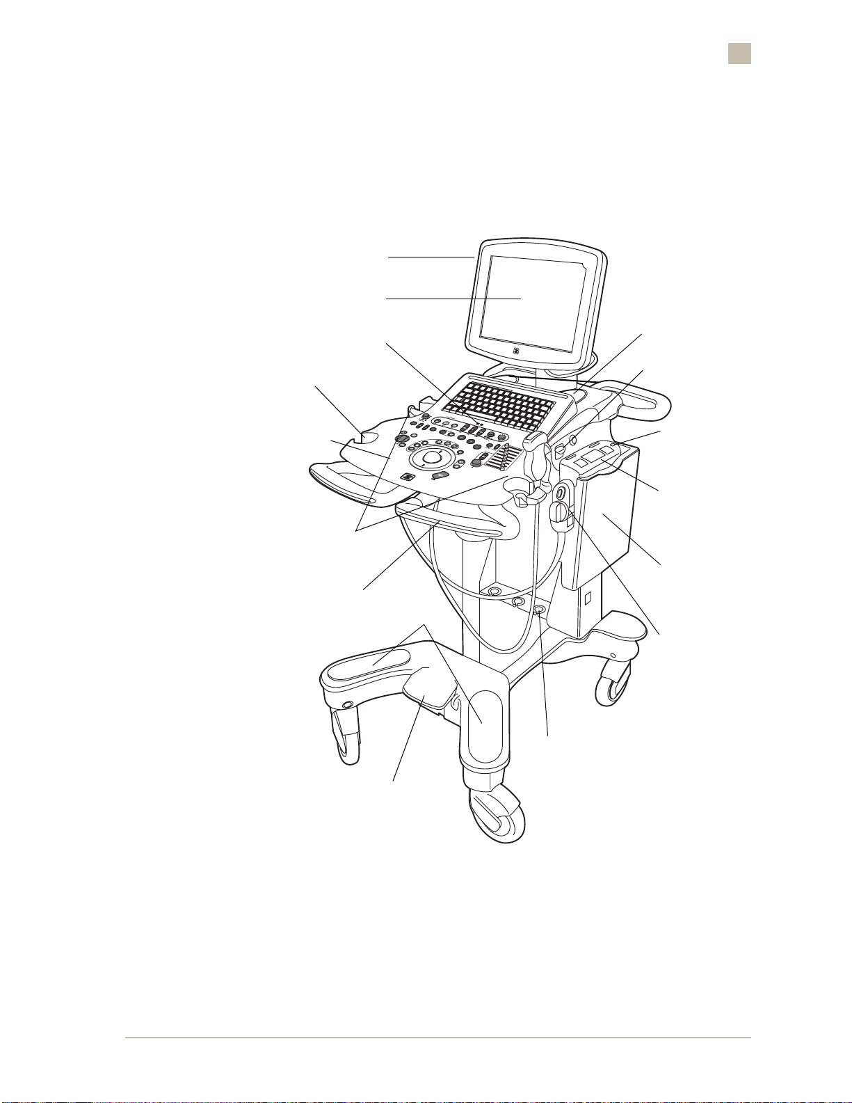
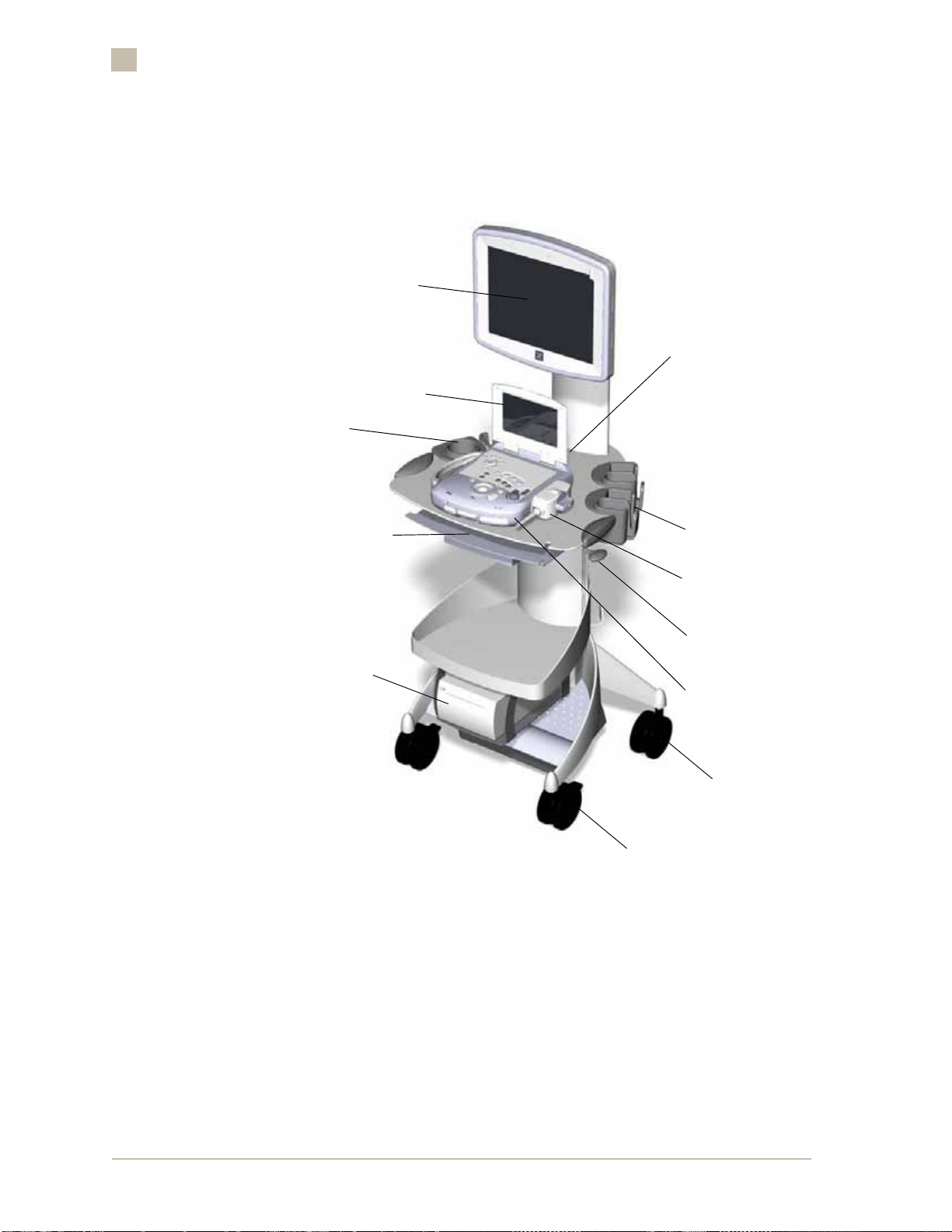
SuperCart
LCD Display Controls
LCD Display
Introduction to the ZONARE z.one
1
Gel Holder
Control Panel
Transducer
Holders
Control Panel
Height Adjust
Microphone
Speakers
Scan Engine Eject
Scan Engine
Power On/Off
Scan Engine
Scan Engine
Pocket
Footrests
Transducer
Connector
Transducer
Connector Holders
Brake Pedal
Figure 1-1. SuperCart with Scan Engine Docked (Front View)
ZONARE Introduction to the ZONARE z.one • 1-3
• 1-3
Page 16
1
Introduction to the ZONARE z.one
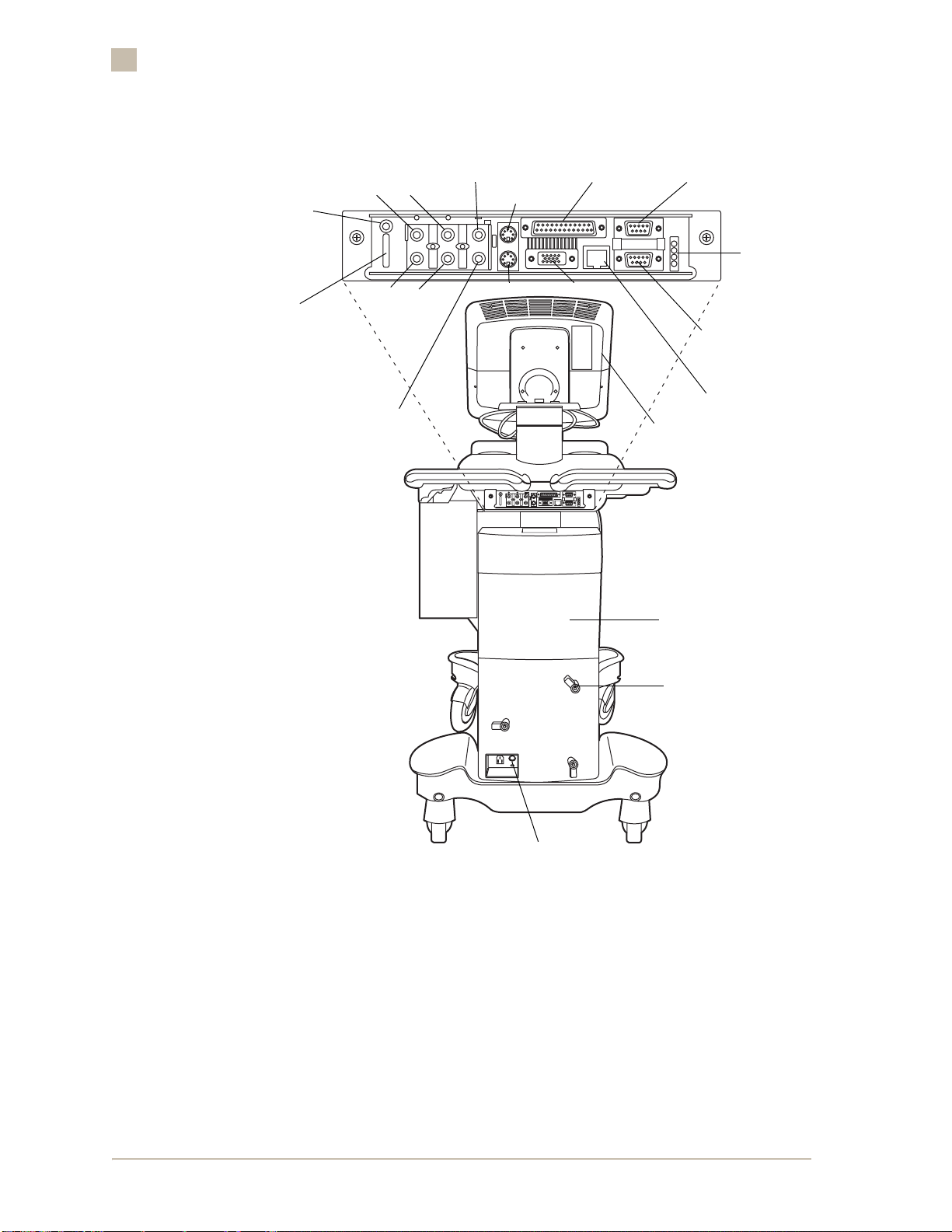
Print
Expose
USB
Audio (In)
L
R
R
Audio (Out)
Composite
Video (Out)
Composite Video
(In)
L
SVHS (Out)
SVHS (In)
LP-2 (Printer Port)
(future use)
VGA (Out)
LCD Display Controls
9 Pin Serial
“Female” DCE
(future use)
LEDs
9 Pin Serial
“Male” DTE
(future use)
Ethernet
(networking)
AC Distribution
Access
AC Power Cord
Wrap Mounts
Circuit Breaker
Figure 1-2. SuperCart with Scan Engine Docked (Back View)
The SuperCart is a full-function ultrasound workstation with a 13-inch LCD
Display, a full-featured control panel, transducer storage, and peripheral and
DICOM connectivity. It is smaller and lighter than conventional systems of
equivalent image quality, and therefore can be used in situations where a
conventional ultrasound system simply would not fit.
The Scan Engine serves as the main processing device (“brains”) for the
SuperCart. For the SuperCart to function, the Scan Engine must be docked
(placed on the docking plate of the SuperCart). Refer to Figure 1-1. When the
1-4 • z.one OPERATOR MANUAL, Version 2.0 ZONARE
1-4 •
Page 17

Scan Engine Docking
Introduction to the ZONARE z.one
Scan Engine is docked, the user can acquire images and carry out
retrospective processing (gain adjustment, sweep speed, etc.) using the fullfeatured control panel. Patient images can be archived (saved) to the internal
flash memory; and if ethernet connectivity is enabled, images can be saved to
the network (DICOM) archive device. Images archived to internal flash
memory can later be recalled for post-study analysis. The user can annotate
images and perform basic measurements.
The Scan Engine pocket, in the SuperCart, is the docking station for the Scan
Engine. It houses the electronic connections between the two z.one
components. When the Scan Engine is docked and the SuperCart main circuit
breaker is powered on, the Scan Engine’s battery is being recharged.
The Scan Engine is the main processing component of the z.one. The push
button power-on/off switch, on the Scan Engine (when the Scan Engine is
docked in the pocket of the SuperCart), serves as the normal power on/off
user control for the z.one. The circuit breaker, located at the rear of the
SuperCart, is normally left in the “On” (up) position at all times (unless the
SuperCart is being prepared for transport or service).
1
SuperCart LCD Display
Figure 1-3. SuperCart LCD Display
The SuperCart has a 13-inch LCD Display, which shows a full-screen view of
the ultrasound image, plus patient and imaging information in designated
areas of the screen. The brightness and contrast settings for the LCD Display
on the SuperCart are adjustable by the user, using the rotary dials located on
the left side of the LCD Display. Refer to Figure 1-8. When an on-screen setup
menu is called up by exercising one of the LCD Display control dials, a
corresponding menu appears briefly in the Control area on the left of the
screen.
ZONARE Introduction to the ZONARE z.one • 1-5
• 1-5
Page 18
1
Introduction to the ZONARE z.one
The LCD display controls include the following:
– Top dial: Controls brightness.
– Middle dial: Controls contrast.
– Bottom dial-push button: Displays a full menu control of monitor
NOTE: For the top and mid dle di als , th e r ecomm en d ed (f actory d ef ault) settin g s are
indicated by an
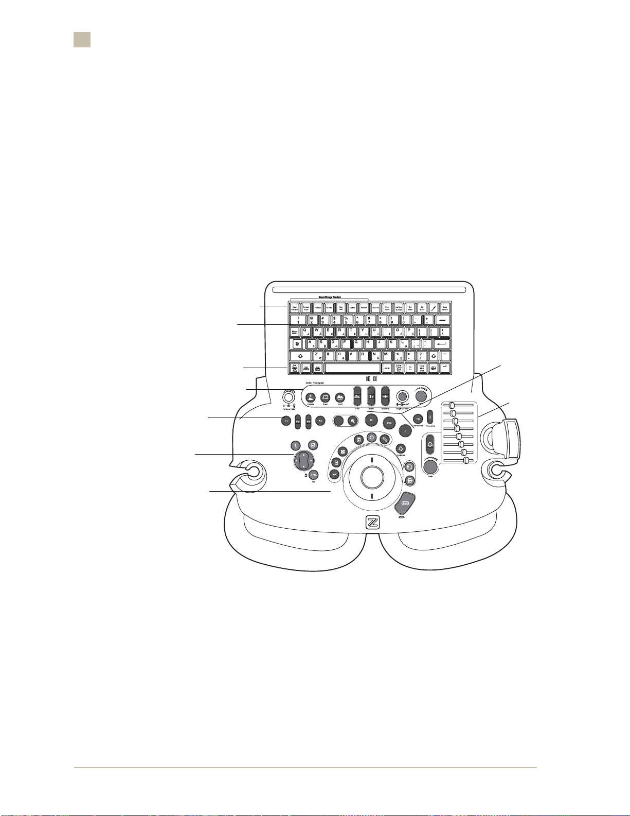
SuperCart Control Panel
Patient Data/
Archive/Review Row
settings (for use by ZONARE service personnel only).
✱ next to the numeric value on the progress bar.
Keyboard
Annotations Row
Doppler Area
Function
Keys
Menu
Controls
Trackball
Cluster
Mode
Keys
TGC
Figure 1-4. SuperCart Control Panel: Overview
The SuperCart control panel features include the following:
■ The keyboard for annotating. This keyboard has additional contr o l keys in
the top and bottom rows for accessing image annotation, archive and
review, and other special functions.
■ The trackball and associated keys, used to position the cursors and to
define the region of interest (ROI) and the Pulsed Wave (PW) gate in the
image area.
1-6 • z.one OPERATOR MANUAL, Version 2.0 ZONARE
1-6 •
Page 19

AC Distribution
Transducer storage
Introduction to the ZONARE z.one
■ The Menu area, containing the Menu Control and keys for navigating
1
menus.
■ The Doppler area, with controls for optimizing color, power, and pulse
wave Doppler images.
■ The Mode keys, for entering and exiting M-mode, Color Doppler mode,
and PW Doppler mode.
■ The 2D control area with toggle/rocker keys, knobs, and Tissue Gain
Compensation (TGC) for image optimization.
The AC Distribution area, at the rear of the SuperCart, houses the I/O cables
for the peripherals, an AC accessory outlet box, and the main circuit breaker
for the SuperCart.
Safe storage for approved z.one transducers is provided on both sides of the
SuperCart.
ZONARE Introduction to the ZONARE z.one • 1-7
• 1-7
Page 20
1
Introduction to the ZONARE z.one
miniCart
LCD Display
Docking
Connector
Scan Engine
LCD Display
Gel Bottle
Holder
Enhanced Keyboard
Sony UP-D897
B/W Printer
(Option)
Locking/Swivel Wheels
Transducer
Holders
Transducer
Lift Release
Handle
Scan Engine
Swivel Wheels
Figure 1-5. miniCart with Scan Engine Docked (Front View)
The miniCart is a compact ultrasound workstation with a 13-inch LCD
Display, full-sized enhanced keyboard, transducer storage, and USB ports to
support peripheral devices and networking (via a USB-to-Ethernet dongle).
The miniCart is smaller and lighter than conventional ultrasound systems of
equivalent image quality, and therefore can be used in situations where a
conventional ultrasound system simply would not fit.
1-8 • z.one OPERATOR MANUAL, Version 2.0 ZONARE
1-8 •
Page 21

Scan Engine Docking
Introduction to the ZONARE z.one
The Scan Engine serves as the main processing device (“brains”) for the
miniCart. For the miniCart to function, the Scan Engine must be docked
(placed on the docking plate of the miniCart). Refer to Figure 1-1. Patient
images can be archived (saved) to the internal flash memory; and if ethernet
connectivity is enabled, images can be saved to the network (DICOM) archive
device. Images archived to internal flash memory can later be recalled for
post-study analysis. The user can annotate images and perform basic
measurements.
Patient images can also be imported or exported to/from the internal
CompactFlash memory of the Scan Engine, utilizing a USB Flash Stick device.
The USB Flash Memory device can be plugged directly into the USB port of
the standalone Scan Engine, or into one of the USB ports on the miniCart
(when the Scan Engine is docked).
The Scan Engine pallet, on the miniCart, is the docking station for the Scan
Engine. It houses the electronic connections between the two z.one
components. When the Scan Engine is docked and the miniCart is powered
on, the Scan Engine's battery is being recharged.
1
The Scan Engine is the main processing component of the z.one. The push
button power-on/off switch, on the Scan Engine serves as the normal power
on/off user control for the z.one.
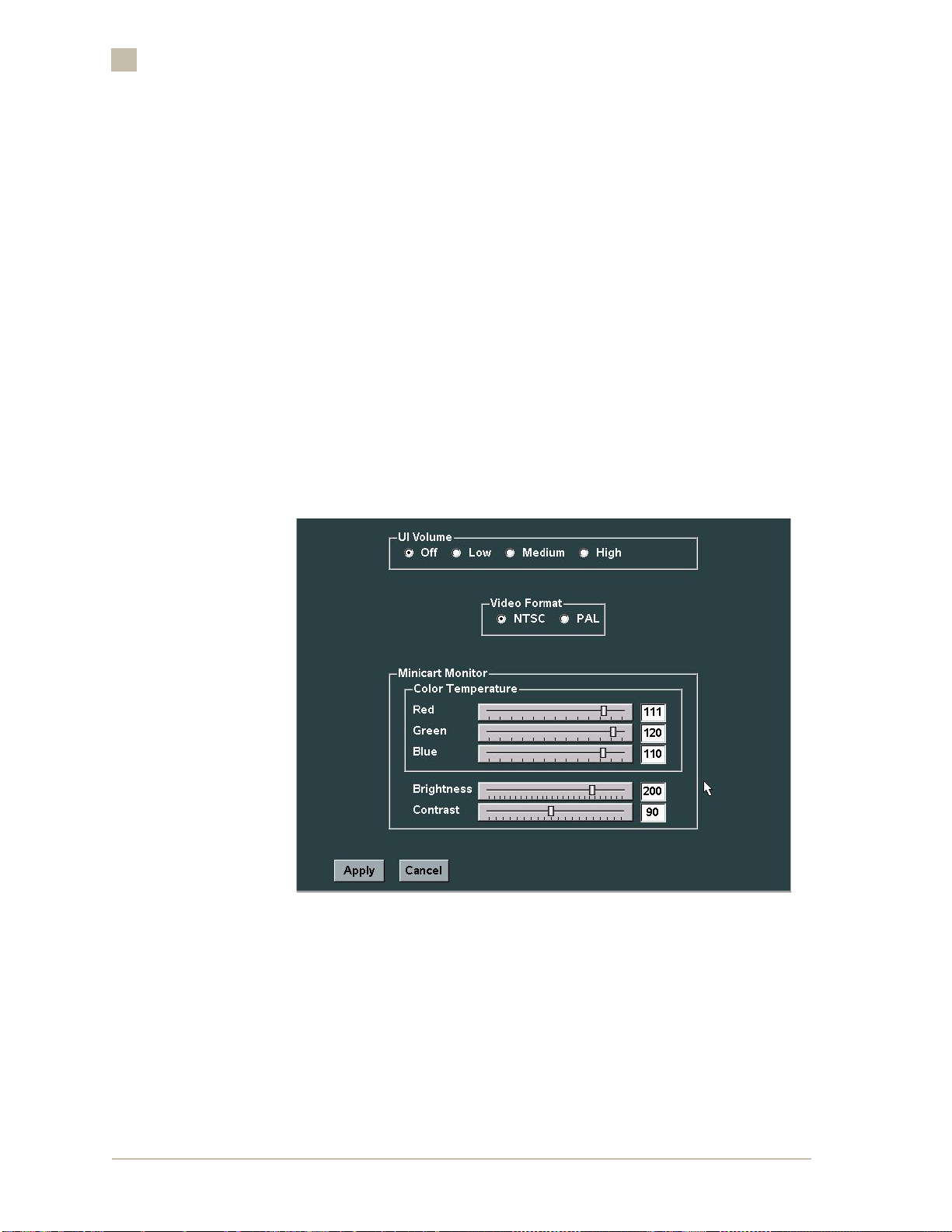
miniCart LCD Display - Video Level Adjustment
Figure 1-6. miniCart LCD Display
The miniCart has a 13-inch LCD Display, which shows a full-screen view of
the ultrasound image, plus patient and imaging information in designated
areas of the screen.
ZONARE Introduction to the ZONARE z.one • 1-9
• 1-9
Page 22
1
Introduction to the ZONARE z.one
Unlike the SuperCart, the LCD Display on the miniCart does not have any
manual adjustment control knobs. All adjustments of the LCD Display on the
miniCart are performed from an on-screen setup menu on the z.one.
The available adjustments are:
–Brightness
–Contrast
– Color Temperature (Red, Green, Blue)
The adjustment of the video settings on the LCD Display, are accomplished by
performing the following steps.
1. Power on the z.one and allow it to fully boot.
2. Select Tools | System Setup | Display | Audio/Video|, to access the
audio/video configuration menu.
Figure 1-7. Audio/Video Configuration Screen (miniCart)
3. Using the trackball, place the cursor arrow to the desired position on
the sliding bar scale (o f th e desire d display contr ol), and pr ess the Set
key to mark the setting.
1-10 • z.one OPERATOR MANUAL, Version 2.0 ZONARE
1-10 •
Page 23
4. Repeat the steps above for any additional display settings that are
desired for change.
5. To s ave the new settin gs and ex it, select Apply from the men u, to save
the configuration and return to the Audio/Video menu.
6. Visually inspect the output of the LCD Display, to confirm the desired
video levels are achieved. Repeat the above steps, if required.
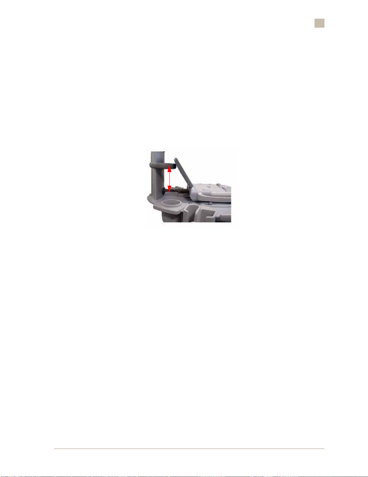
Cart Scan Engine Display Backstop
Introduction to the ZONARE z.one
1
Figure 1-8. miniCart Scan Engine Display Backstop
The miniCart incorporates a custom display backstop that serves to hold the
Scan Engine Touchscreen display in place while in use. Without the backstop,
a user pushing on the Touchscreen display would soon find the display
positioned in an undesirable use position.
The miniCart backstop can slide up and down the miniCart display column to
allow the user to change the angle of the Scan Engine LCD display.
ZONARE Introduction to the ZONARE z.one • 1-11
• 1-11
Page 24
1
Introduction to the ZONARE z.one
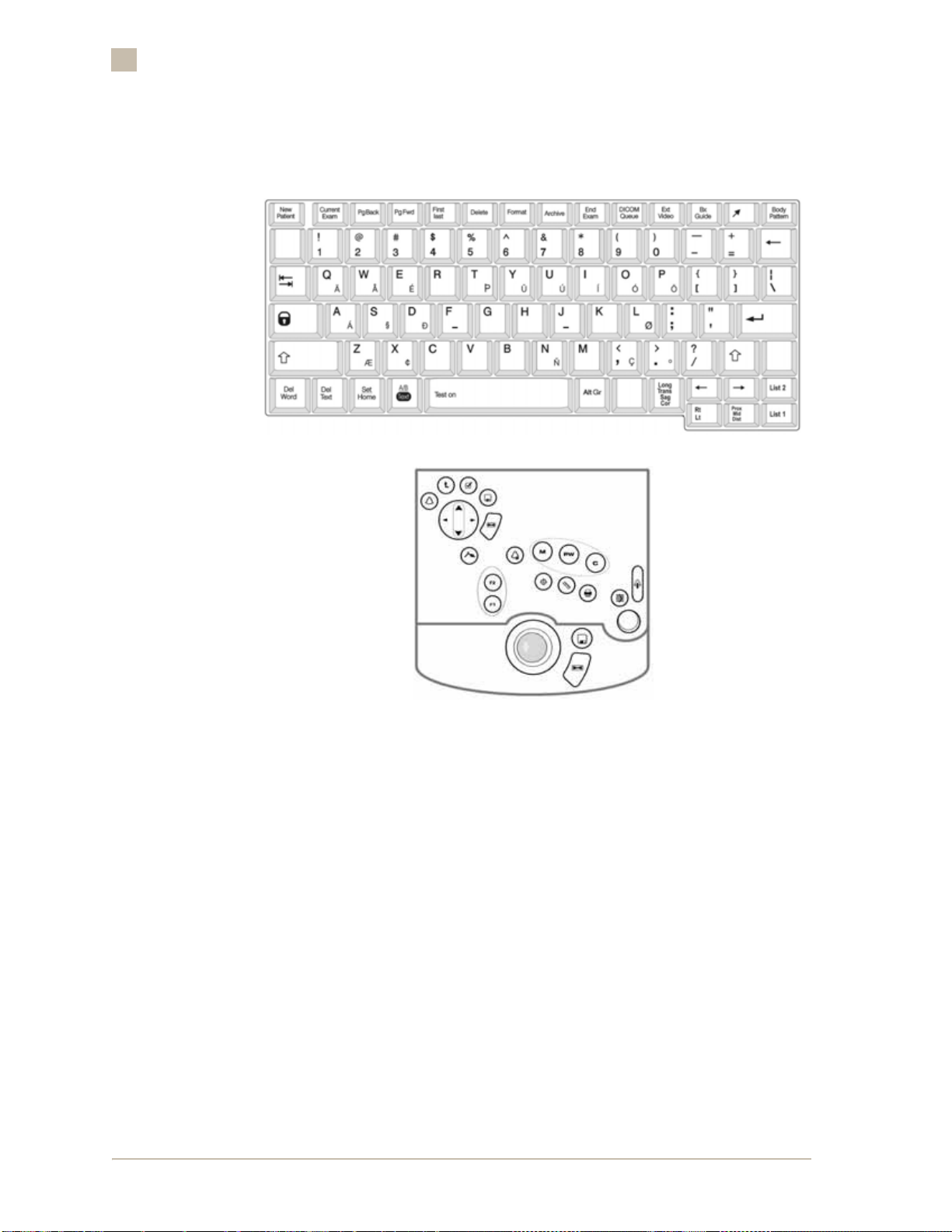
miniCart Controls
Figure 1-9. miniCart Enhanced Keyboard & Scan Engine Controls: Overview
In the miniCart configuration of the z.one system, mode selections, user
menus and most basic operations are performed using trackball and buttons
on the control panel of the Scan Engine. In addition to the control panel, the
Scan Engine’s flip-up display serves as a touchscreen for the user to quickly
activate a number of the z.one system functions.
An enhanced keyboard is also included in the miniCart configuration of the
z.one system. The enhanced keyboard is located beneath the miniCart's
scanning pad, on a pull out shelf. The enhanced keyboard contains standard
text keys for annotating, as well as dedicated function keys (in the top and
bottom rows) for accessing image annotation, archive/review, and other
special system operations.
1-12 • z.one OPERATOR MANUAL, Version 2.0 ZONARE
1-12 •
Page 25
AC Distribution
The miniCart has an AC inlet and fuse holder. The miniCart also contains an
AC plug, available for use with the Sony UP-D897 Black & White Printer.
The only AC powered peripheral permitted to be used with the miniCart
supplied AC plug is the Sony UP-D897 B&W printer. Any other peripheral's
usage would require that the user validate the usage to IEC60601.
Fuse Replacement:
Use T6.3A 250V slo-blow fuses when operating the miniCart in a 100-120VAC
environment. Use Littlefuse part number 021806.3HXP or equivalent.
Use T3.15A 250V slo-blow fuses when operating the miniCart in a 200220VAC environment. Use Littlefuse part number 02183.15HXP or
equivalent.
miniCart Mobile Transport
Introduction to the ZONARE z.one
1
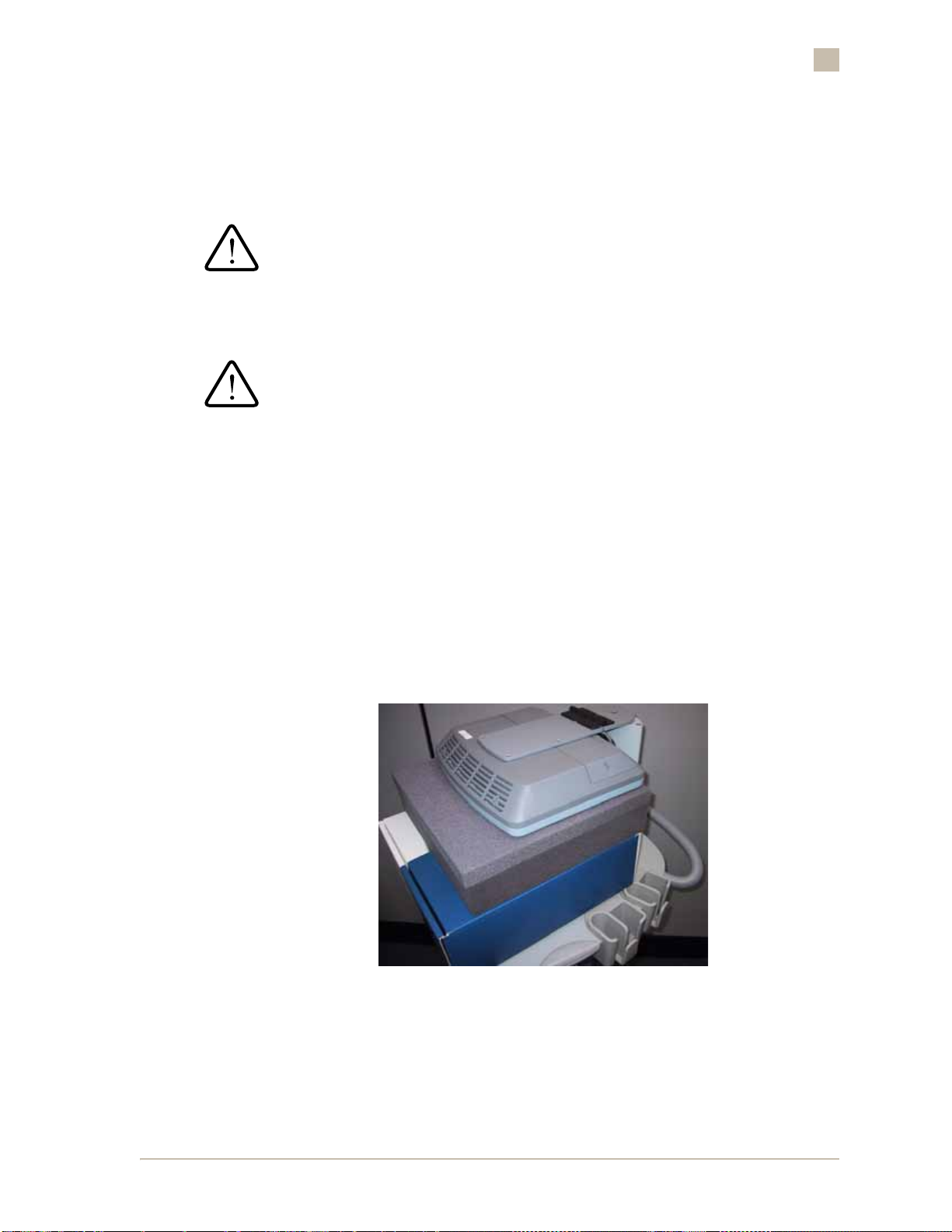
To prevent potential damage to the miniCart’s LCD display monitor and
mounting hardware, from shock and vibration that may occur during mobile
transport (while loaded in a vehicle), a foam support pad should be placed
between the bottom surface of the LCD display and the lily pad docking
surface of the miniCart
The combined height of the foam support should be tall enough to hold the
LCD at a horizontal fold-down position (as shown below).
Figure 1-10. miniCart LCD Display Support (Mobile Transport)
Transducer Storage
Safe storage for approved z.one transducers is provided on both sides of the
miniCart.
ZONARE Introduction to the ZONARE z.one • 1-13
• 1-13
Page 26
1
Introduction to the ZONARE z.one
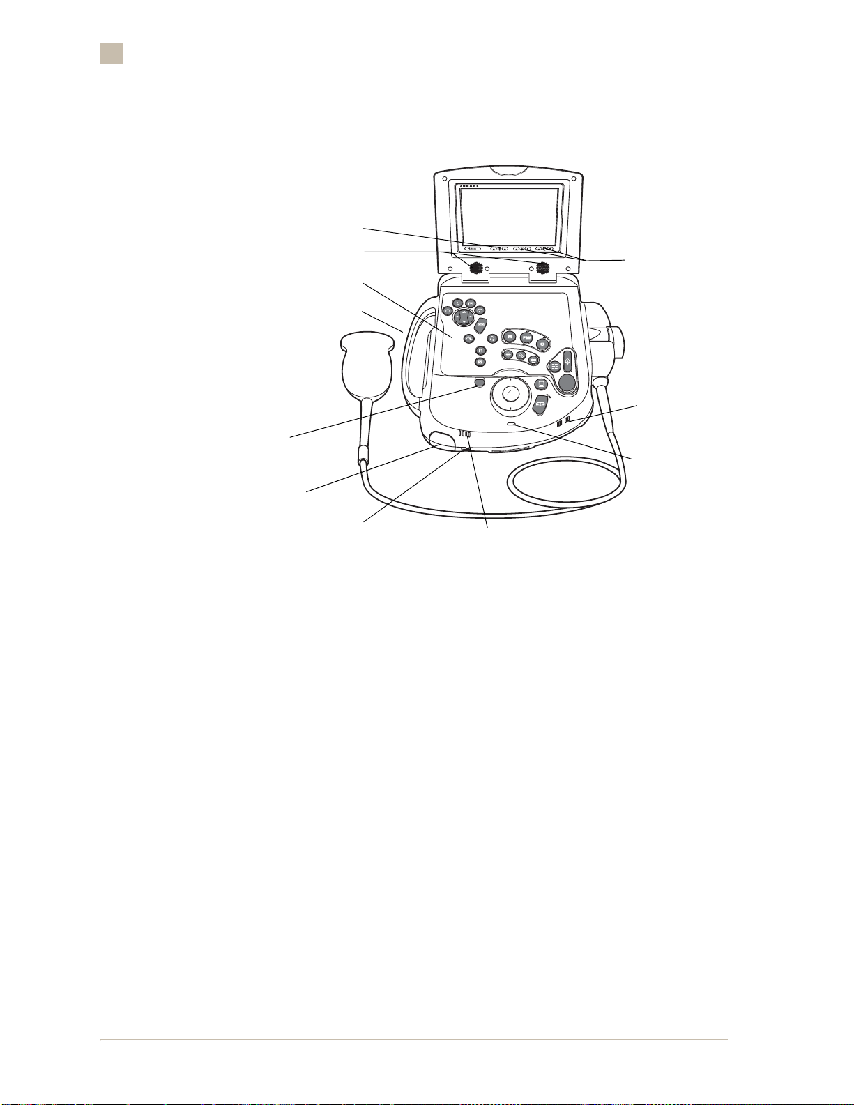
Scan Engine
LCD Display
Touchscreen
Speaker Volume Control
Speakers
Control Panel
Handle
Display
Release
Battery
Battery Eject
Battery Charge Level
Figure 1-11. Scan Engine with Transducer (Front View)
Stylus
(Behind the
LCD Display)
Contrast/
Brightness
Controls
Microphone
Power On
Indicator
1-14 • z.one OPERATOR MANUAL, Version 2.0 ZONARE
1-14 •
Page 27
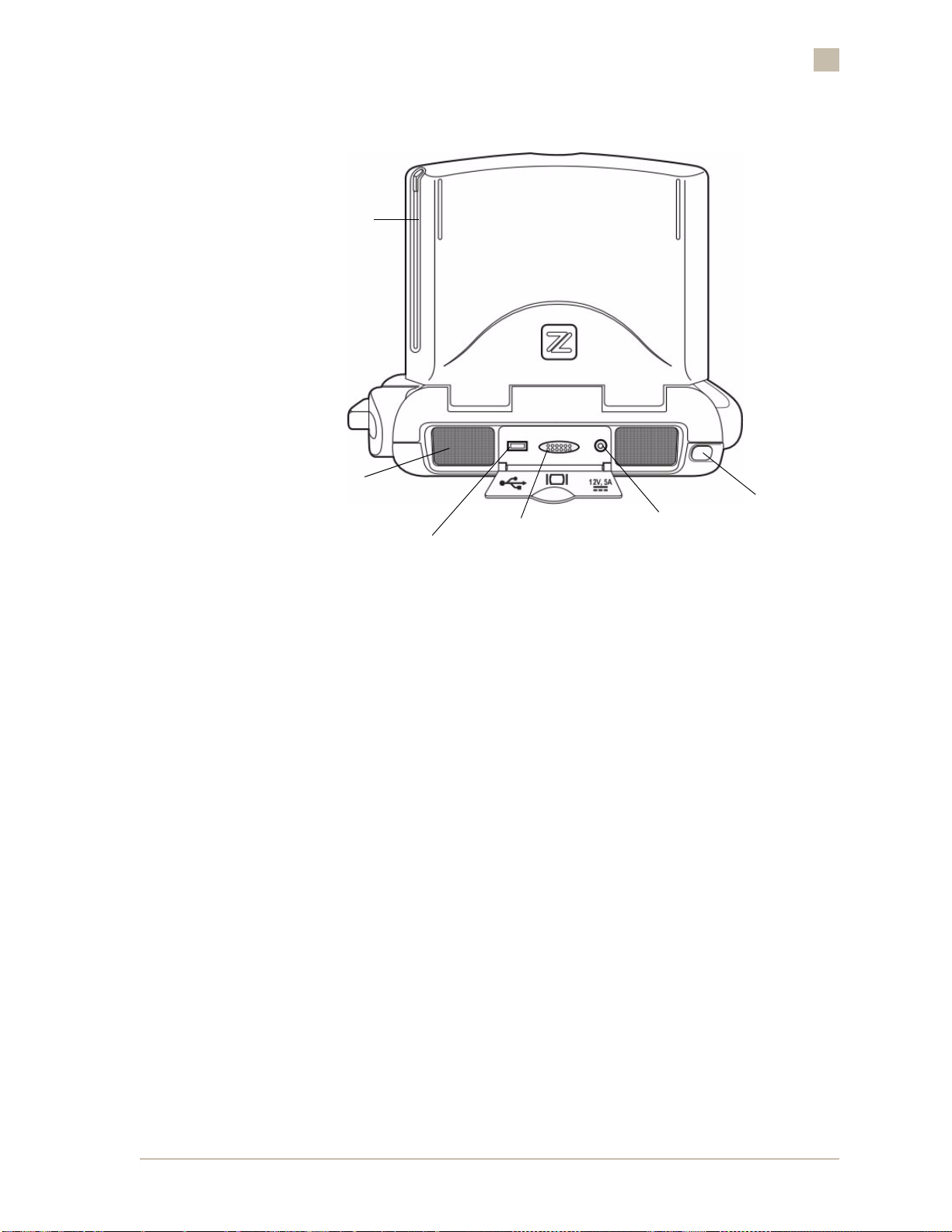
Stylus
Introduction to the ZONARE z.one
1
Cooling Fan Opening
USB 2.0 Port
External Video
(DVI Port)
+12V Power In
(From AC Power Pack)
Power Switch
Figure 1-12. Scan Engine (Back View)
The Scan Engine contains the z.one system software. It can be used for
complete examinations or limited procedures. When the Scan Engine is
docked, images are processed internally using the 13” LCD Display on the
SuperCart (or miniCart). When the Scan Engine is undocked, images are
displayed on the Scan Engine’s local LCD Display and user operations are
performed on the Scan Engine’s local compact control panel.
The Scan Engine is powered by an internal rechargeable battery (or the
optional AC adapter) when the Scan Engine is being operated in an undocked
condition. The Scan Engine's internal battery is automatically being recharged
anytime the Scan Engine is docked to an AC powered Supercart or miniCart.
ZONARE Introduction to the ZONARE z.one • 1-15
• 1-15
Page 28
1
Introduction to the ZONARE z.one
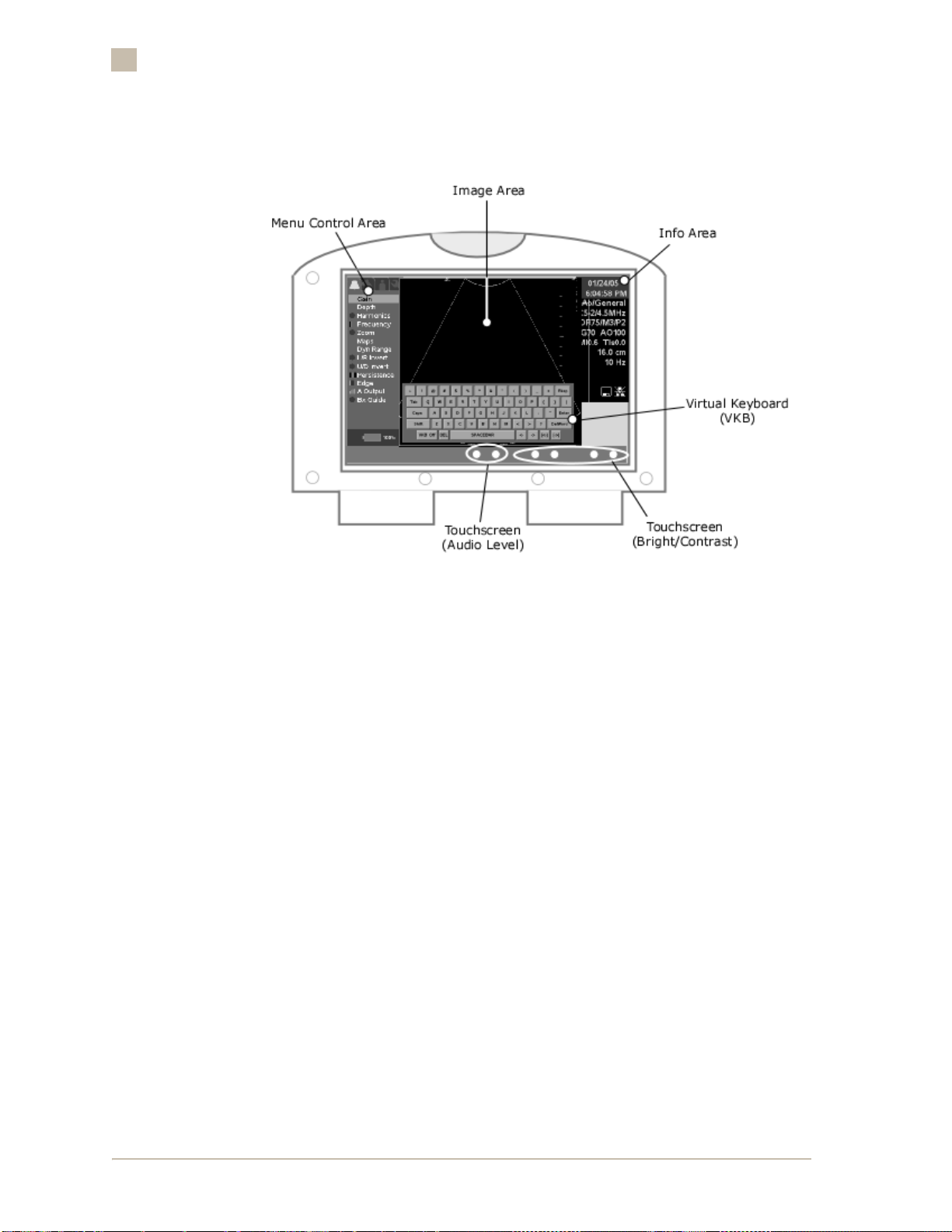
Scan Engine LCD Display
Figure 1-13. Scan Engine LCD Display Layout
The Scan Engine LCD Display is divided into the Image area in the center , the
Control area on the left, and the Info area on the right. The Image area
displays the sonogram, plus patient and image information in designated
areas of the screen. Refer to Figure 1-13. The active on-screen menu displays
in the Control area.
A touchscreen keyboard, called the V irtua l Keyboard (VKB), can be displayed
on the LCD Display of the Scan Engine. The VKB enables the user to make
standard alpha-numeric data entries when the Scan Engine is being operated
in an undocked condition from the SuperCart (or miniCart).
The VKB is used for all functions requiring user data entry. Free-text
annotations and other text/data entry operations (e.g., patient data entry and
system configuration data entry) are inserted by touching virtual
alphanumeric keys on the touchscreen, with the stylus.
The bezel surrounding the display includes additional touchscreen
functionality. These functions include adjustments for brightness and contrast
of the Scan Engine’s LCD Display, and local speaker audio volume.
1-16 • z.one OPERATOR MANUAL, Version 2.0 ZONARE
1-16 •
Page 29
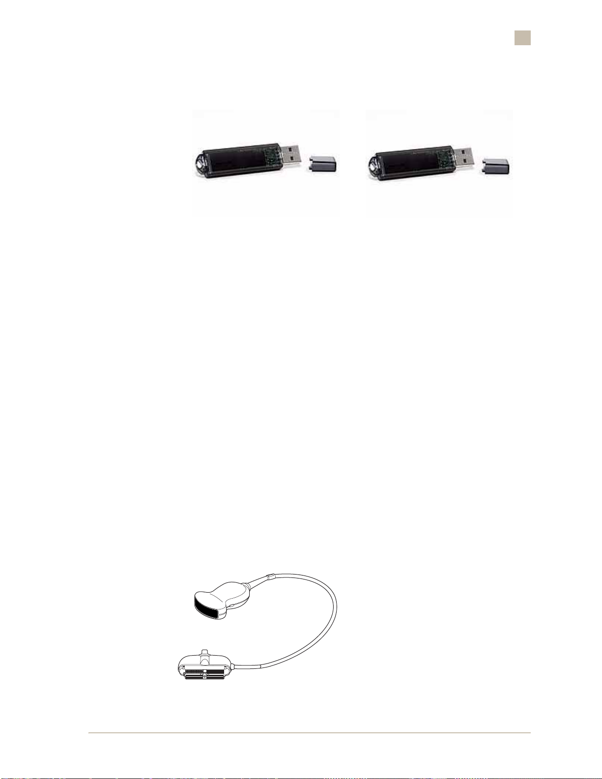
USB Memory Sticks
Figure 1-14. USB Memory Sticks
The z.one uses removable USB Memory sticks as the method for storage of
patient image files and user Preset and user System configuration files. In
addition, a USB Memory Stick is used as the source media for installing/
upgrading system software on the Scan Engine.
Introduction to the ZONARE z.one
1
Transducers
There are two USB Memory Sticks that supplied at the time of system
installation, which should be maintained at each system site. It is
recommended that each USB Memory Stick ONLY be used for its own
dedicated purpose (i.e. not storing patient images on the system/preset
backup USB Memory Stick). The dedicated USB Memory Sticks that should
be maintained at each z.one customer site are:
■ 1) Software Installer & User Presets/System Backup
■ 2) Patient Image Archive
WARNING: The USB Mem ory Sticks suppli ed by ZONARE are the r ecommen ded bran d,
type and sizes for use in the z.one. These USB Memory Sticks have been tested and
verified for optimum reliability and performance. If the User outsources their own
brand and size of USB Memory Stick, ZONARE is not responsible for any errors
associated with file corruption, or file transfer time increases.
Figure 1-15. Transducer
ZONARE Introduction to the ZONARE z.one • 1-17
• 1-17
Page 30

1
Introduction to the ZONARE z.one
The z.one transducers are lightweight and have a number of ergonomic
features to maximize the ease of use for the user. These features include tactile
orientation markers and grip ridges. Transducer holders on both sides of the
SuperCart (or miniCart) provide safe and accessible storage. Refer to “To
connect a z.one transducer” on page 2-19.
Table 1-1.
Transducer Exam Type Biopsy Guide
C5–2 Abdominal
E9–4 Obstetrics
L8-3 Peripheral Vascular
L10-5 Thyroid
P4-1 Deep Abdominal
P10-4 Neonatal
Yes
Abdominal Vascular
Obstetrics
Fetal Heart
Gynecology
Yes
Gynecology
Yes
Pediatric Hips
Difficult Small Parts
Yes
Breast
Scrotum
Pediatric Hips
Small Parts
Peripheral Vascular
To be rele ased
Trauma
Abdominal Vascular
Obstetrics
Fetal Heart
Gynecology
To be rele ased
Pediatric Head - Abdomen
Vascular
Intraoperative
The z.one transducers have a specific range of acceptable application of use.
ZONARE recommends that each transducer’s use be restricted exclusively to
those applications.
1-18 • z.one OPERATOR MANUAL, Version 2.0 ZONARE
1-18 •
Page 31

SuperCart Peripherals
ZONARE offers a number of optional medical grade (conform to the
requirements of IEC 60601-1) peripherals. The peripherals currently offered
for the SuperCart consist of the following:
■ Sony UP-897MD B&W Thermal Video Printer
■ Sony UP-21MD Color Thermal Video Printer
■ Panasonic LQ-MD800 DVD Video Recorder
Instructions for proper use of each peripheral are covered in the
manufacturer’s instructions for use documents.
miniCart Peripherals
ZONARE offers an optional medical grade (conforms to the requirements of
IEC 60601-1) peripheral. The only peripheral device currently offer ed for the
miniCart consists of the following:
Introduction to the ZONARE z.one
1
■ Sony UP-D897 B&W USB Digital Printer
Instructions for proper use of peripherals are covered in the manufacturer’s
“Instructions For Use” documents.
DICOM Connectivity
DICOM connectivity is an optional software feature on the z.one. When
activated and configured, DICOM connectivity enables the medical image
and associated patient and exam data to be transmitted over the institution’s
network. The connectivity provided by DICOM enhances the efficiency of the
storage and output of medical imaging data. Refer to DICOM store and print
information in “DICOM Connectivity” on page 8-1 for more information.
When DICOM is activated and configured, DICOM Store, DICOM Print, and
DICOM Worklist functions may be enabled.
Contact and System Information
If you have any questions, see ZONARE’s Web site at www.zonare.com.
ZONARE Medical Systems Inc.
1061 Terra Bella Avenue
Mountain View, CA 94043-1839
To contact Tech Support, call: 650-316-3199
ZONARE Introduction to the ZONARE z.one • 1-19
• 1-19
Page 32

1
Introduction to the ZONARE z.one
For other contact numbers, refer to “Contact Information for ZONARE
Service and Technical Support” on page 11-1.
1-20 • z.one OPERATOR MANUAL, Version 2.0 ZONARE
1-20 •
Page 33

Getting Started
SuperCart & miniCart Moving Cautions
Introduction
Getting Started
2
2
The information in this section is intended to provide recommendations and
cautions for the user to follow when moving (rolling) the SuperCart or
miniCart over a variety of possible surfaces.
To move the SuperCart or miniCart
NOTE: ALWAYS follow these precautions when moving the SuperCart or miniCart.
1. Lower the adjustable height to MINIMUM.
CAUTION: To m aximize the stability o f the SuperCart or miniCart during movement
across irregular surfaces , the user sh ould use the r elease lever to adjust the hei ght o f
the User Interface/LCD Display assembly to its LOWEST possible position, PRIOR to
relocation of the unit.
Lever
SuperCart
Figure 2-1. Height Release Lever Positioning (SuperCart & miniCart)
miniCart
2. Fold the LCD Display down to a horizontal position.
ZONARE Getting Started • 2-1
• 2-1
Page 34

2
Getting Started
CAUTION: To prevent possible damage to the LCD Display on the SuperCart or
miniCart, during transport of the unit, always rotate the LCD Display to the facing-
forward position and then fold it downward into a horizontal position (as shown in
Figure 2-2).
NO
YES
Figure 2-2. LCD Display Position
3. Ensure that the transducer cables are wrapped over the cable hooks.
CAUTION: To prevent possible damage to the cables of the transducer s, from the
wheels of the SuperCart or miniCart during movement of the unit, ensure that they
are wrapped over the cable hooks (provided at the front of the system) such that
they are suspended above the floor (as shown in Figur e 2-3).
YES
Figure 2-3. Do’s for Transducer Cables
YES
4. For movement over normal smooth surfaces, push the SuperCart or
miniCart from the rear handle(s), with the pivoting front wheels
leading.
CAUTION: To ensure maximum maneuverability and stability (to prevent potential
tipping) of the SuperCart, wh en moving th e SuperCart over normal sm ooth surfaces it
should be pushed with the pivoting wheels leading, and the fixed wheels trailing.
2-2 • z.one OPERATOR MANUAL, Version 2.0 ZONARE
2-2 •
Page 35

Getting Started
YES
2
Figure 2-4. User Position During Normal Cart Movement
5. When moving th e SuperCart or miniCart over obstacles, alw ays pull the
Cart from the front (or back); do not push.
CAUTION: To prevent possible tipping of the SuperCart or miniCart, anytime it is
being moved over a surface that has an elevation change (doorway lip, pavement
seam, etc.), the user must ensure that the Cart is pulled across (the operator
leading the Cart over the obstacle), rather than pushed.
NO
YES
Figure 2-5. Cart Wheel Position over Obstacles
NO
YES
Figure 2-6. User Position During Cart Movement over Obstacles
ZONARE Getting Started • 2-3
• 2-3
Page 36

2
Getting Started
Security Locking of the Scan Engine
To ensure the security of the Scan Engine (from possible theft, etc), a
removable key locking mechanism is provided on the z.one. The key lock will
enable/disable the removal of the Scan Engine from the pocket of the
SuperCart, or the lily pad on the miniCart.
The key lock is located, as shown in the pictures below.
SuperCart Key Lock
Figure 2-7. Scan Engine Security “Locking” in SuperCart or miniCart
Docking and Undocking the Scan Engine
To en sure th e security o f the Scan En gine (fr om possible th eft, etc), a To work with
either the SuperCart or the miniCart, the Scan Engine must be docked. The
docking two mechanisms are quite different; this section will describe the
docking mechanism of the two
All imaging functions are available on the Scan Engine when it is undocked
from either the SuperCart or the miniCart.
To dock the Scan Engine in the SuperCart
Hold the Scan Engine with the front panel facing down into the Scan Engine
pocket on the SuperCart. Line up the track on the bottom surface of pocket
with the tracks on the bottom of the Scan Engine. Gently push it into place
until a positive “click” is heard.
miniCart Key Lock
2-4 • z.one OPERATOR MANUAL, Version 2.0 ZONARE
2-4 •
Page 37

Figure 2-8. Scan Engine Docking in SuperCart
Getting Started
2
To undock the Scan Engine from the SuperCart
Press the ejection latch above the Scan Engine pocket. The Scan Engine is
ejected partially out of the pocket. Grasp and remove the Scan Engine.
ZONARE Getting Started • 2-5
• 2-5
Page 38

2
Getting Started
To dock the Scan Engine on the miniCart
Hold the Scan Engine centered (horizontally) and rearward above the lily pad
on the miniCart. Line up the tracks on the top surface of lily pad with the tracks
on the bottom of the Scan Engine. While resting flat on the lily pad surface,
gently slide the scan engine directly towards you (forward), to engage it on
the docking latches. Continue to slide the Scan Engine towards you, until a
positive audible "click" is heard.
Open the I/O access door at the rear of the Scan Engine, and connect the
docking connector cable assembly to the mating connectors on the Scan
Engine.
Lily Pad & Docking
Connector
Scan Engine Docking “IN”
Figure 2-9. Scan Engine Docking in miniCart
2-6 • z.one OPERATOR MANUAL, Version 2.0 ZONARE
2-6 •
Page 39

Getting Started
2
To undock the Scan Engine from the miniCart
Disconnect the docking connector cable assembly from the mating connectors
on the rear of the Scan Engine.
Figure 2-10. Scan Engine Undocking from miniCart
Slide (press rearward) the ejecti on latch (located in the upper left corner of the
lily pad), to release the Scan Engine from the lily pad. Grasp the Scan Engine
and slide it away from you (rearward) to release it from the docking latches.
Lift the Scan Engine to remove it from the miniCart.
Powering On and Off
Please read and understand all Warnings and Cautions in “Warnings and
Cautions” on page 9-3 before powering on the z.one.
Powering on the z.one
SuperCart:
1. Locate the circuit breaker (located at the left/rear of the SuperCart)
on the SuperCart and move it to the On (up) position. Refer to
Figure 2-11.
miniCart:
NOTE: The miniCart does not have a separate power switch or circuit breaker
2. Locate the power button on the back left of the Scan En gine . Press th e
button. Refer to Figure 2-11.
ZONARE Getting Started • 2-7
• 2-7
Page 40

2
Getting Started
Power Button
AC Power Receptacle Circuit Breaker
Figure 2-11. Scan Engine Power Button and SuperCart Circuit Breaker
3. The z.one will take approximately one minute to complete the normal
power on sequence.
4. To verify successful power on, check the SuperCart display to ensure
the following.
The ZONARE start-up screen displays while the system is initializing.
When initializing is complete, the system is ready for B-mode imaging.
Figure 2-12. ZONARE Start-up Screen
NOTE: If the start-up screen does not display, the system failed to power on.
Completely eject the Scan Engine from th e SuperCart pock et an d visu ally in spect the
Scan Engine. Reinsert the Scan Engine and try to power on. Refer to “Contact
Information for ZONARE Service and Technical Support” on page 11-1.
Password Protection (Access Control)
Password protection can be enabled on the z.one to pr event unauthorized
use of the system. The Access Control menu is used for configuring the
log-on password.
CAUTION: If password protection (Access Control) is elected to be used to restrict
access to the
retained in a safe place by the System Administrator.
2-8 • z.one OPERATOR MANUAL, Version 2.0 ZONARE
2-8 •
z.one, it is extremely important that the user-assigned password be
Page 41

Getting Started
If Access Control is configured by the User in this menu, and the user-assigned
password is subsequently lost or forgotten; no master password is available for
recovering access to the z.one for normal operation. A complete r e-installation of
system software will be required to regain normal use of the
z.one.
2
Figure 2-13. Access Control Screen
1. If password log-on has been configured, a log-on screen will appear.
Enter the previously configured password to enable system operation.
2. To connect a transducer, refer to “To connect a z.one transducer” on
page 2-20.
3. To install a USB Memory Stick, refer to “Inserting and Removing USB
Memory Stick Media” on page 2-11.
A USB Memory Stick icon is displayed on the right of the screen. If a USB
Memory Stick is not installed, the icon is displayed with an X through it.
Verify that the card has sufficient storage memory available to store exam
images. To install a USB Memory Stick or check the available memory ,
refer to “Inserting and Removing USB Memory Stick Media” on
page 2-11.
If the screen is blank or is otherwise not the default display, check the
transducer connections and, if necessary, reconnect the transducer. If a
normal display is still not present, connect a different transducer. If the
normal display is not present with the second transducer, power the
system off and call Tech Support. Refer to “Contact Information for
ZONARE Service and Technical Support” on page 11-1.
To power off the SuperCart
NOTE: Normally the SuperCart’s main AC circuit breaker power is left on, even when
the z.one has been shutdown from normal use (using the Scan Engine power on/off
switch). However, any time the SuperCart is being moved the following SuperCart
power off sequence should be followed.
ZONARE Getting Started • 2-9
• 2-9
Page 42

2
Getting Started
1. Press the Scan Engine power button. The Scan Engine takes about
10 seconds to perform a normal shutdown sequence, and then powers
off.
2. Move the SuperCart circuit breaker (located at the left/rear of the
SuperCart) to the off (down) position.
To power on the Scan Engine (undocked)
1. Ensure that the Scan Engine battery is charged. Refer to “Installing
and Removing a Battery” on page 2-12.
2. Locate the power button on the back of the Scan Engine, and press
the button.
Power Button
Figure 2-14. Scan Engine Power Button
3. To check the Scan Engine display, ensure the following:
– The ZONARE start-up screen displays while the system is initializing.
When initializing is complete, the system is ready for B-mode
imaging.
– If the screen is blank or is otherwise not the default display, check the
transducer connections and reconnect the transducer. If a normal
display is still not present, connect a different transducer. If the
normal display is not present with the second transducer, power the
system off and call Tech Support. Refer to “Contact Information for
ZONARE Service and Technical Support” on page 11-1.
– A USB Memory Stick icon displays on the right of the screen when a
stick is installed. Verify that the stick has sufficient storage memory
available to store exam images. To install USB Memory Stick media or
check the available memory, refer to “Inserting and Removing USB
Memory Stick Media” on page 2-11.
4. To log in to the z.one, enter the password in the Password data field.
If password protection is enabled on the system, the log-on screen
displays.
2-10 • z.one OPERATOR MANUAL, Version 2.0 ZONARE
2-10 •
Page 43

Getting Started
5. To connect a transducer, refer to “To connect a z.one transducer” on
page 2-20.
6. To install a USB Memory Stick, refer to “Inserting and Removing USB
Memory Stick Media” on page 2-11.
To power off the Scan Engine
Press the Scan Engine power button. The Scan Engine takes about 10 seconds
to perform a normal shutdown sequence, and then powers off.
Inserting and Removing USB Memory Stick Media
The z.one utilizes removable USB Memory sticks for two (2) specific
purposes.
■ Software Installer & User Preset - System Backup
■ Patient Image Archive
2
12V, 5A
USB Connector Port
Figure 2-15. USB Memory Stick and Scan Engine (Rear View)
Rear access bay door
USB Memory Stick
To install a USB Memory Stick
A USB Memory Stick can be installed while the z.one is powered on or off.
ZONARE Getting Started • 2-11
• 2-11
Page 44

2
Getting Started
1. Open the rear bay door.
2. Position the USB Memory stick in front of the USB connector port of
the Scan Engine.
3. To insert the USB Memory Stick, hold it with the proper orientation.
Push the USB Memory Stick gently all the way into the USB port slot.
To remove a USB Memory Stick
CAUTION: It is important to ensure that the Scan Engine has fully completed
accessing (writing/editing/deleting) data on USB Memory Stick, PRIOR to removing
it from the Scan Engin e . Failur e to observe this caution, by ejectin g th e USB M emo ry
Stick at any time that it is being accessed, will result in loss of data!
1. To eject th e USB Memory Stick, firmly grasp the USB Memory Stick on
either side with your fingers, and pull it out all the way.
Installing and Removing a Battery
Figure 2-16. z.one Battery
To install a battery
NOTE: Ensure that the Scan Engine has been removed from the SuperCart before
installing/replacing the battery.
1. To verify th e char ge on th e battery, refer to “Checking Battery Char ge”
on page 2-13.
2. To in stall th e battery, locate the battery pocket on the left side of th e
Scan Engine. Line up the prominent groove on the battery with the
correspondin g ton gue on the left insid e surf ace of the battery pocket.
2-12 • z.one OPERATOR MANUAL, Version 2.0 ZONARE
2-12 •
Page 45

Push the battery in until it is fully seated and latched in place. The
battery charge indicators (on the Scan Engine to the right of the
battery pocket) light up.
To eject a battery
Push the battery release latch to the right of the battery pocket.
Checking Battery Charge
A charge indicator on the labeled surface of the battery has four LEDs lined
up with four small holes in the label. To check the charge on a battery, press
the circle to the left, which is the Charge Indicator test button.
Another charge indicator on the front panel of the Scan Engine has four LEDs
that light up briefly when the battery is installed.
Charge remaining Indicator
Getting Started
2
<25% 1 LED
25–49% 2 LEDs
50–74% 3 LEDs
≥75%
The battery operating range is as follows:
Usage Duration (approximate values)
Active use 30-60 Minutes
Standby mode 2.0–3.0 hours
Storage mode
(in Scan Engine)
4 LEDs
(dependent on modes and display brightness)
3 weeks
ZONARE Getting Started • 2-13
• 2-13
Page 46

2
Getting Started
When the Scan Engine is powered on, the percentage of battery charge
remaining is displayed in the Status area of the screen. When the charge
becomes low, the battery icon in the Status area changes color and on-screen
messages display as follows:
Charge remaining Indicator
<25% Battery icon turns amber.
<5% Battery icon flashes, followed by a system
Battery Thermal Protection
WARNING: To protect the z.one battery from potential thermal damage, the
system monitors the temperature of the battery at all times. If the battery is
detected as exceedin g the maximum safe operating temperature, a warning message
will appear on the display of the z.one.
shutdown message.
The Operator should immediately complete all active operations, in preparation for
the system automatically initiating a power-down sequence.
2-14 • z.one OPERATOR MANUAL, Version 2.0 ZONARE
2-14 •
Page 47

Battery Charger, 2-Bay: Connection & Use
Getting Started
2
Figure 2-17. Battery Charger, 2-Bay
The battery pack inside the z.one Scan Engine is recharged during normal use,
when the Scan Engine is docked in the SuperCart, and the SuperCart has AC
power applied.
During standalone (undocked) operation, the Scan Engine will require
replacement with a freshly charged battery pack after approximately 1 hour
of continuous use. The 2-Bay Battery Charger should be used for maintaining
the charge of spare battery packs, and occasional recalibrating ( reconditioning),
of the z.one battery packs to maximize their operational efficiency.
The two functions of the 2-Bay Battery Charger are:
■ ""Charge" mode:The battery receives a single full charging cycle
■ ""Recalibration" mode:The battery is discharged -> charged -> discharged
again - final charged
ZONARE Getting Started • 2-15
• 2-15
Page 48

2
Getting Started
Recalibrating (Reconditioning) a Battery Pack
1. Connect the AC power cable to an active wall outlet, and connect the
DC power cable between the power supply and the 2-Bay Battery
Charger
2. Insert the battery pack into the LEFT bay o f th e 2-Bay Battery Char g er
(Note: Only the LEFT bay performs "Recalibration")
3. Press the "Recalibrate" button on the 2-Bay Battery Charger
During the "Recalibrate" process, the left status LED flashes ORANGE. Once
the "Recalibrate" process is completed, this same LED will intermittently flash
between ORANGE and GREEN.
NOTE: The "Recalibrate" process may require 14 hours to fully complete
The battery pack should NOT be removed prior to completion of the "Recalibrate"
process, as the battery will be at an unknown level of charge
Charging a Battery Pack
1. Connect the AC power cable to an active wall outlet, and connect the
DC power cable between the power supply and the 2-Bay Battery
Charger
2. Insert the battery pack into the EITHER bay of the 2-Bay Battery
Charger
3. The charging cycle on the docked battery pack will automatically
begin to execute
4. During the "Charging" process, the corresponding status LED flashes
GREEN. Once the "Charging" process is completed, this same LED
becomes solid GREEN.
NOTE: The "Charging" process, in the two bays of the unit, is performed in a
"sequential" fashi on. If two battery packs ar e docked into the 2-Bay Battery Char g er
at the same time, the charger will perform the complete charging sequence on one
battery pack, before starting the charging sequence on the second battery
2-16 • z.one OPERATOR MANUAL, Version 2.0 ZONARE
2-16 •
Page 49

LED Status Indicators: Battery Charger
Getting Started
2
Figure 2-18. LED Status Indicator Definitions
ZONARE Getting Started • 2-17
• 2-17
Page 50

2
Getting Started
AC Power Adapter: Connection & Use
Figure 2-19. AC Power Adapter - 2.0 Scan Engine
For extended (more than 1 hour) standalone (undocked) use of the Scan
Engine, the AC Power Adapter should be used. The AC Power Adapter is
plugged into the +12VDC power connector, located inside the rear panel
access door at the back of the Scan Engine.
To connect the AC Power Adapter
NOTE: Ensure that the Scan Engine has been removed from the SuperCart before
using the AC Battery Pack
1. Power off the Scan Engine, and ensure it is being used remotely
(ejected) from the SuperCart.
2. Connect the DC Power Cable to the +12VDC connector at the rear of
the Scan Engine (located inside the rear access door).
3. Connect the output connector o f the DC P ower Cable (out of th e P ower
Supply) to the DC Adapter Cable's mating connector
4. Plug the AC Power Cable's female connector into the socket on the
Power Supply
5. Plug the other end of the AC Power Cable into an active AC wall outlet
2-18 • z.one OPERATOR MANUAL, Version 2.0 ZONARE
2-18 •
Page 51

Getting Started
6. Inspect the Power-On indicator lamp on the Power Supply, to ensure
power is applied and the unit is on
7. Power on the Scan Engine and begin normal operation
2
ZONARE Getting Started • 2-19
• 2-19
Page 52

2
Getting Started
Connecting and Disconnecting a Transducer
Transducer
Locking
Knob
Figure 2-20. z.one Transducer
Locked
Connection Port
Transducer
Connection Board
To connect a z.one transducer
A transducer can be connected or disconnected while the z.one is powered on
or off.
1. Verify the integrity of the transducer and the connectors.
WARNING: Before each use the transducer must be inspected to avoid risk of
injury. Inspect the transducer face, housing, cable, connectors, and cases. Do
not use the unit if damage is detected.
2. Insert the tran sducer’s connector into the alignm ent hole on the Scan
Engine’s transducer connection board, and ensure it is fully seated.
3. Turn the locking knob on the transducer connector one quarter turn
clockwise, to lock the transducer in place. Refer to Figure 2-20.
2-20 • z.one OPERATOR MANUAL, Version 2.0 ZONARE
2-20 •
Page 53

Getting Started
4. Verify a proper connection, by the presence of an initial “initializing
transducer” messag e which should appear on the LCD Display. This
also indicates that th e tran sdu cer has been pr operly recognized by th e
z.one.
5. After approximately 10 seconds, the system should automatically
begin actively operating the transducer in B-mode. A basic B-mode
image should now be displayed in the Image area of the LCD Display.
2
To disconnect a z.one transducer
1. To disconnect the transducer from the Scan Engine, turn the locking
knob one quarter turn counter clockwise and r emove the transducer
connector from the transducer connection port. Refer to Figure 2-20.
NOTE: A “No transducer connected” message should be displayed on the LCD
Display.
2. To store the transducer, place it in the transducer connection holders
on the SuperCart. Refer to Figure 1-1.
Applying a Transducer Cover
To apply a transducer cover
1. To prepare the cover, remove it from the packaging. Apply water-
based ultrasound gel to the inside of the cover.
2. To place the cover on the transducer, pull the cover secure ly over the
transducer and remove any wrinkles or air bubbles. Secure the cover
to the transducer with plastic bands.
ZONARE Getting Started • 2-21
• 2-21
Page 54

2
Getting Started
Attaching a Biopsy Guide
To attach a reusable (nondisposable) biopsy guide
1. To attach th e biopsy gui d e to the tr an sd u cer, refer to the biopsy guid e
product information.
2. To apply a sterile transducer cover, refer to “Applyin g a Transducer
Cover” on page 2-21.
3. To attach a disposable sterile needle guide attachment to the biopsy
guide, the transducer cover remains in place, and the needle guide is
attached over it.
4. To activate the on-screen biopsy needle guide graphics, do the
following:
SuperCart: Press Bx Guide (top row of SuperCart keyboard keys).
Scan Engine: Activate the Imaging tab. On the B-mode menu, select
Biopsy Guide.
The relative path of the needle (2 lines or more) displays on the sonogram.
Refer to the biopsy-needle instructions enclosed with the biopsy guide.
To attach a disposable biopsy guide (EV exam only)
1. To apply a sterile transducer cover, refer to“Applying a Transducer
Cover” on page 2-21.
2. To attach a sterile disposable biopsy guide, attach the biopsy guide
over the transducer cover. A disposable biopsy guide is a needle and
needle guide in one piece. Ensure that the biopsy guide is locked.
3. Apply another sterile transducer cover (optional).
4. To activate the on-screen biopsy needle guide graphics, do the
following:
SuperCart: Press Bx Guide (top row of SuperCart keyboard keys).
Scan Engine: Activate the Imaging tab. On the B-mode menu, select
Biopsy Guide.
The relative path of the needle (2 lines or more) displays on the sonogram.
Refer to the biopsy-needle instructions enclosed with the biopsy guide.
Mechanical Controls
Brakes SuperCart: The brake mechanism of the SuperCart allows the user to lock
rotation and swivel (in 90-degree increments) of the front wheels, to prevent
2-22 • z.one OPERATOR MANUAL, Version 2.0 ZONARE
2-22 •
Page 55

Getting Started
undesired movement during system operation. Pressing downward fully on
the brake pedal will lock the front wheels on the SuperCart from rolling. In
addition, the front wheels may be rotated to a 90-degree angle prior to locking
the brake, if desired, to provide additional stability during shipping. Pr essing
the brake pedal downward a second time will release the wheels.
2
Figure 2-21. Brake Pedal (SuperCart)
miniCart: The brake mechanism of the miniCart allows the user to lock
rotation (brake) of the front wheels, to prevent undesired movement during
system operation. Pressing “Down” fully on the brake lever, on each of the
two front wheels, will lock them from rolling. Lifting “Up” on each of the
brake levers, will release the wheels.
Figure 2-22. Brake Levers (miniCart)
Height
adjustment
ZONARE Getting Started • 2-23
The z.one SuperCart and miniCart include a hydraulic lift mechanism that
enables the user to optimize the vertical position (height) of the user interface
panel and LCD Display for optimum comfort and viewing during operation.
SuperCart: Pull inward on the release lever, located on the inside of the right-
front handle assembly on the SuperCart, allows the height of the SuperCart to
be adjusted. Releasing the spring-loaded release lever locks the assembly into
the current vertical position.
miniCart: Bracing your palm against the rubber handre st, pull upwards on the
release lever, located on the right side of the miniCart, to release the
mechanism. Hold the lever in the up position, until the desired height is
• 2-23
Page 56

2
Getting Started
achieved. Releasing the spring-loaded release lever locks the assembly into
the current vertical position.
LCD Display
position
SuperCart
miniCart
Figure 2-23. Height Adjustment Release Lever
The LCD Display is mounted to a swivel mechanism that allows for rotation
and tilting, to enable the user to optimize visibility of the screen. The tilt angle
may be adjusted by grasping the sides of the LCD Display and pivoting to the
desired viewing angle. The LCD Display should be tilted fully forward to a
horizontal position when the SuperCart is being transported.
NOTE: The LCD Display contains an internal tilt-angle sensor switch that is used to
blank the screen (g o in to a sleep mode) when the LCD Display is folded forwar d past
an angle of approximately 60 degrees. This automatic blanking (and unblanking) of
the LCD Display, while tilting it fore-aft, is normal on the z.one SuperCart.
Figure 2-24. LCD Display Positioning (SuperCart)
In addition, the LCD Display may be rotated on its sw ivel base to allow better
viewing when the user is positioned on either side of the SuperCart while
performing a patient examination.
miniCart:
On the miniCart, for exclusively using centralized (centere d) viewing, or for
locking the LCD Display from rotating during transport, a spring loaded
center-locking pin is provided. The knob for positioning the locating pin, is
located below the display pedestal. For unrestricted rotation, the centerlocating pin can be positioned into a constant Off (retracted) position, by
pulling fully down on the knob and rotating it approximately 90 degr ees.
2-24 • z.one OPERATOR MANUAL, Version 2.0 ZONARE
2-24 •
Page 57

Repeating the rotation of the knob to one of the two 180 degree release
positions, will restore the center-locking operation.
Figure 2-25. LCD Display Rotation & Locking (miniCart)
miniCart Enhanced Keyboard Access
To provide full functionality, when the Scan Engine is docked, the miniCart
includes an Enhanced Keyboard. The Enhanced Keyboard is mounted to a
retractable shelf that allows for stowage during system transport. To access
the Enhanced Keyboard, grasp either edge of the retractable shelf, and slide it
towards you.
Getting Started
2
Figure 2-26. miniCart Enhanced Keyboard Access
ZONARE Getting Started • 2-25
• 2-25
Page 58

2
Getting Started
SuperCart Rear I/O Panel
On the rear of the SuperCart, there is an input/output (I/O) panel for
connecting peripheral devices.
2
6
5
3
4
11
1
910
78
Figure 2-27. SuperCart Rear I/O Panel
Table 2-1 explains the connector functions.
Table 2-1. Connector Functions
Jack # Function Direction
1 Remote Print “Expose” (External Printer Trigger) Output
2 Parallel Printer (currently not supported) Output
3 RS-232 Serial Port A (Export Calc Data) Input/Output
4 RS-232 Serial Port B (Export Calc Data) Input/Output
5 Ethernet 10/100BaseT - (Network) Input/Output
6 SVGA Video - (External Monitor) Output
7 S-Video, NTSC/PAL - (OUT = bottom, IN = top) Input/Output
8 Composite Video, NTSC/PAL - (OUT = bottom,
IN = top)
9 Audio, LEFT - (OUT = bottom, IN = top) Input/Output
10 Audio, RIGHT - (OUT = bottom, IN = top) Input/Output
11 USB (2.0) Port (to be supported 2.0> Software) Input/Output
Input/Output
2-26 • z.one OPERATOR MANUAL, Version 2.0 ZONARE
2-26 •
Page 59

miniCart Rear I/O Panel
The miniCart includes an integrated USB 2.0 compliant hub. Two of the hub’s
ports are brought out to external connections for operator use.
Figure 2-28. miniCart Rear I/O Panel (USB Hub)
Getting Started
USB Hub
2
ZONARE Getting Started • 2-27
• 2-27
Page 60

2
Getting Started
User Controls
The “User Control” on the z.one includes keys, menu items, Menu Control,
and a trackball. Detailed information on the control, relevant to each system
operating modality, are discussed in the respective chapter and section.
SuperCart User Interface Functions
Figure 2-29. SuperCart User Interface Layout
2-28 • z.one OPERATOR MANUAL, Version 2.0 ZONARE
2-28 •
Page 61

Number System Control Description
1 TGC Slidepots Changes gain of image at discrete depth.
Getting Started
2
2
3
4
5
6
7
GAIN
DEPTH
FREQUENCY
HARMONICS
FREEZE
PRINT
Changes master gain of Tissue image in B-Mode and M-Mode.
Rocker switch enables increasing/decreasi n g im ag ing depth of the
display.
Rocker switch enables increasing/decr easing transmit frequency.
Toggles the activation/deactivation of tissue harmonics imaging
mode.
Halts or restarts active imaging on the display.
Sends current image to device(s) pr eviously specified in System Setup
menu (internal compactflash, DICOM printer, DICOM store). When
external printer is selected, key press initiates external print trigger
signal to
B/W printer .
8
9
10
11
12
13
STORE
OPTIMIZE
MEASURE
SET
CALC
DELETE (Calc)
NOTE: The PRINT key may also be configured to initiate the same
storage operations as the STORE key.
Stores current still image, or clip store sequence, to device(s)
previously specified in System Setup menu (internal c ompactflash,
DICOM printer , DICOM store). When external printer is selected, key
press also initiates external “print trigger” signal to the external
printer.
Enables Auto DGC and Sound Speed Correction
Brings up dynamic caliper (live) or calculation menu (frozen).
Used to toggle the function of active items on display.
Brings up Calculation tools on the display.
Deletes active Calculation tool from the display.
ZONARE Getting Started • 2-29
• 2-29
Page 62

2
Getting Started
Number System Control Description
14
REPORT (Calc)
Displays the Calculation Worksheet/Report for the active Exam Type.
15
16
17
18
19
20
21
DUAL
ENTER (Calc) /
DUAL:Toggle
C
PW
M
ZOOM
DUAL
TAB
Shared function key:
Calc Ops: Key ends the current Calc process, and produces a result.
DUAL Mode: Toggles between two side-by-side displayed images, in
selecting which will be “Active”/”Selected”
Color (Doppler) Mode, activates/deactivates.
Pulsed Wave (Doppler), activates/deactivates.
M-mode (tissue motion), activates/deactivates.
Initiates the variable image magnification process.
Activates the DUAL imaging (side-by-side) mode
Advances through four on-screen menus (Imaging, Presets, Patient
Info, Tools).
22
23
24
25
26
27
Menu Control
SELECT
BACK
F1-F4
VOLUME-MIC
Trackball
COLOR/DOPPLER CONTROLS
28
GAIN
Functions like a computer mouse or joystick, for scrolling through the
on-screen menu selections
Up/Down arrows scroll to selections
Left/Right arrows toggle through values
Activates currently highlighted selection in the on-screen menu.
Returns back one window, in the on-screen display menu.
Function keys, user configurable in System Setup menu.
Push-button (in center) turns on/off microphone activation. Rotary
knob (outer ring) changes the on-board speaker volume.
Used for positioning the cursor , de fining size/position of ROE in color
mode, positioning measurement tools, reviewing clip store images,
and navigating form/tables/worksheets/reports.
Changes master gain for Color and PW Doppler modes.
2-30 • z.one OPERATOR MANUAL, Version 2.0 ZONARE
2-30 •
Page 63

Number System Control Description
29
ANGLE
CORRECT
Push-button activates/toggles Doppler angle correction tools. Rotary
knob makes fine adjustments to angle correction.
Getting Started
2
30
31
32
33
34
35
BASELINE
SCALE
FILTER
INVERT
STEER
UPDATE
SIMULTANEOUS
(DUAL):
Changes Doppler Velocity (PW and Color) zero reference baseline.
Changes Doppler Velocity (PW and Color) range.
Changes high-pass filter, used in Color and PW.
Switches the blood flow mapping direction, in Color and PW.
Toggles through 3 (center, left, right) steered Doppler options for
Linear transducer(s).
Shared function key: Toggles Doppler update modes, or toggles
Simultaneous sub-set operation in DUAL mode
PW Doppler: Toggles between three possible update modes.
1) Simultaneous live updating of the PW and 2D imaging mode(s) (Bmode in duplex, and B-mode and Color in triplex)
2) Live updating of PW strip with a frozen 2D reference image
3) Live updating of 2D mode image with a frozen PW strip
DUAL Mode: Toggles On/Off Simultaneous (side-by-side) update
ZONARE Getting Started • 2-31
• 2-31
Page 64

2
Getting Started
SuperCart Keyboard Functions
Figure 2-30. SuperCart Keyboard Layout
Table 2-2. SuperCart Keyboard Functions
Key System Control Description
NEW PATIENT This is a toggle key. The first press displays
the Patient Information page. The second
press returns to the imaging display.
CURRENT EXAM If there is an exam in progress, pressing this
key displays the in-progress exam's images,
with the most recently stored image
displayed first. If there is no exam in
progress, pressing this key has no effect.
PG BACK This key only works when in an in-progress
exam review or in an archived exam review.
Pressing this key displays the previous
image or a page of images if in a multiimage display format. If there are no further
images, the key press has no effect.
PG FWD Same as PG BK, except the image advances
in direction.
FIRST LAST This key only works when in an in-progress
exam review or in an archived exam review.
Pressing this key toggles the display
between the first stored image (or first page
of images in a multi-image display format)
and the last stored image (or last page of
images in a multi-image display format).
2-32 • z.one OPERATOR MANUAL, Version 2.0 ZONARE
2-32 •
Page 65

Table 2-2. SuperCart Keyboard Functions
Key System Control Description
DELETE This key only works when in an in-progress
exam review or in an archived exam review.
When an image has been selected, pressing
the Delete key tags the image for deletion by
drawing a red X through it. If the selected
image already has been tagged for deletion
(red X), pressing the Delete key removes the
red X, untagging the image.
FORMAT This key only works when in an in-progress
exam review or in an archived exam review.
Pressing this key toggles the display
between the following image formats:
■ 2 x 2 [displaying 2 rows of 2 images (4
images)]
■ 3 x 2 [displaying 2 rows of 3 images (6
images)]
■ A full-size image
ARCHIVE This is a toggle key. The first press displays
the Patient Selection Table. The second press
returns to imaging.
Getting Started
2
END EXAM When an exam is in progress, pressing the
End Exam key closes the exam. If no exam is
in progress, pressing this key has no effect.
DICOM QUEUE This is a toggle key. The first press displays
the DICOM queue. The second press returns
to imaging.
EXT VIDEO External Video. This is a toggle key. There
are three options:
■ The first press selects external S-Video
(from the rear I/O panel) to display on
the SuperCart’s monitor.
■ The second press selects external
composite video in (from the rear I/O
panel) to display on the SuperCart’s
monitor.
■ The third press returns to using internal
z.one system video (VGA) to display on
the SuperCart’s monitor.
BX GUIDE Biopsy guide. This is a toggle key. There are
two options:
■ The first press displays the biopsy needle
path guide.
■ The second press removes the biopsy
needle path guide.
ZONARE Getting Started • 2-33
• 2-33
Page 66

2
Getting Started
Table 2-2. SuperCart Keyboard Functions
Key System Control Description
(Arrow) This is a toggle key. It works when the image
is live or frozen. Pressing the key displays an
arrow graphic in the middle of the display.
Up to 15 arrows may be displayed
simultaneously.
BODY PATTERN This is a toggling key. Pressing the Body
Pattern key displays a Body Pattern for the
Exam Type in use. Pressing the key again
removes the displayed Body Pattern W hen a
Body Pattern is displayed, pressing left/
right on the Omni will cycle through all
available Body Patterns.
DEL WORD | DEL TEXT Pressing Del Text removes all text
annotations and arrow graphics displayed.
Pressing Shift + Del Word deletes the most
recently entered text annotation, whether it
is free text, POT, or List entry.
SET | HOME Pressing Home moves the text annotation
cursor to its default home position. Pressing
Shift + Set Home will set the current cursor
position as the new Home position.
A/B | TEXT Pressing Text will display the text
annotation cursor. Pressing Text again will
remove the text annotation cursor.
Shift + A/B Text is not implemented.
ALT GR Used in conjunction with the QWERTY
keyboard to support international
characters.
LONG TRANS SAG COR This is a cycling key. Pressing this key will
cycle between displaying LONG, TRANS,
SAG, and COR.
RT LT This is a cycling key. Pressing this key will
cycle between displaying RIGHT and LEFT.
PROX MID DIST This is a cycling key. Pressing this key will
cycle between displaying PROX, MID, and
DIST.
LIST 2 | LIST 1 This is a cycling key. Pressing List1 will
cycle between displaying items entered in
List1. Pressing Shift+List2 will cycle between
displaying the items entered in List2.
2-34 • z.one OPERATOR MANUAL, Version 2.0 ZONARE
2-34 •
Page 67

miniCart Enhanced Keyboard Functions
Getting Started
2
Figure 2-31. miniCart Enhanced Keyboard Layout
Table 2-3. miniCart Enhanced Keyboard Functions
Key System Control Description
NEW PATIENT This is a toggle key. The first press displays
CURRENT EXAM If there is an exam in progress, pressing this
PG BACK This key only works when in an in-progress
PG FWD Same as PG BACK, except the image
the Patient Information page. The second
press returns to the imaging display.
key displays the in-progress exam's images,
with the most recently stored image
displayed first. If there is no exam in
progress, pressing this key has no effect.
exam review or in an archived exam review.
Pressing this key displays the previous
image or a page of images if in a multiimage display format. If there are no further
images, the key press has no effect.
advances in forward direction
FIRST LAST This key only works when in an in-progress
exam review or in an archived exam review.
Pressing this key toggles the display
between the first stored image (or first page
of images in a multi-image display format)
and the last stored image (or last page of
images in a multi-image display format).
ZONARE Getting Started • 2-35
• 2-35
Page 68

2
Getting Started
Table 2-3. miniCart Enhanced Keyboard Functions
Key System Control Description
DELETE This key only works when in an in-progress
exam review or in an archived exam review.
When an image has been selected, pressing
the Delete key tags the image for deletion by
drawing a red X through it. If the selected
image already has been tagged for deletion
(red X), pressing the Delete key removes the
red X, untagging the image.
FORMAT This key only works when in an in-progress
exam review or in an archived exam review.
Pressing this key toggles the display
between the following image formats:
■ 2 x 2 [displaying 2 rows of 2 images (4
images)]
■ 3 x 2 [displaying 2 rows of 3 images (6
images)]
■ A full-size image
ARCHIVE This is a toggle key. The first press displays
the Patient Selection Table. The second press
returns to imaging.
END EXAM When an exam is in progress, pressing the
End Exam key closes the exam. If no exam is
in progress, pressing this key has no effect.
DICOM QUEUE This is a toggle key. The first press displays
the DICOM queue. The second press returns
to imaging.
EXT VIDEO External Video. This is a toggle key. There
are three options:
■ The first press selects external S-Video
(from the rear I/O panel) to display on
the SuperCart’s monitor.
■ The second press selects external
composite video in (from the rear I/O
panel) to display on the SuperCart’s
monitor.
■ The third press returns to using internal
z.one system video (VGA) to display on
the SuperCart’s monitor.
2-36 • z.one OPERATOR MANUAL, Version 2.0 ZONARE
2-36 •
Page 69

Table 2-3. miniCart Enhanced Keyboard Functions
Key System Control Description
BX GUIDE Biopsy guide. This is a toggle key. There are
two options:
■ The first press displays the biopsy needle
path guide.
■ The second (and subsequent) presses
will cycle through the display of the
available needle path guide displays,
removes the biopsy needle path guide
after all paths have been displayed.
(Arrow) This is a toggle key. It works when the image
is live frozen. Pressing the key displays an
arrow graphic in the middle of the display.
Up to 15 arrows may be displayed
simultaneously.
BODY PA TTERN This is a toggling key. Pressing the Body
Pattern key displays a Body Pattern for the
Exam Type in use. Pressing the key again
removes the displayed Body Pattern. When
a Body Pattern is displayed, pressing left/
right on the Omni will cycle through all
available Body Patterns.
DEL WORD Pressing Del W ord deletes the most r ecently
entered text annotation, whether it be free
text, POT, or List entry.
Getting Started
2
DEL TEXT Pressing Del Text removes all text
annotations and arrow graphics displayed,
and resets the cursor to the current Home
position.
SET | HOME Pressing Home move the text annotation
cursor to its default home position. Pressing
Shift + Set Home will set the current cursor
position as the new Home position.
A/B | TEXT Pressing Text will display the text
annotation cursor. Pressing Text again will
remove the text annotation cursor.
Shift + A/B Text is not implemented.
ALT GR Used in conjunction with the QWERTY
keyboard to support international
characters.
LONG TRANS SAG COR This is a cycling key. Pressing this key will
cycle between displaying LONG, TRANS,
SAG, and COR.
RT LT This is a cycling key. Pressing this key will
cycle between displaying RIGHT and LEFT.
ZONARE Getting Started • 2-37
• 2-37
Page 70

2
Getting Started
Table 2-3. miniCart Enhanced Keyboard Functions
Key System Control Description
PROX MID DIST This is a cycling key. Pressing this key will
LIST 1 Pressing List1 will display item s entered in
LIST 2 Pressing List1 will display item s entered in
Scan Engine User Interface Functions
cycle between displaying PROX, MID, and
DIST.
List1.
List 2.
Figure 2-32. Scan Engine User Interface Layout
2-38 • z.one OPERATOR MANUAL, Version 2.0 ZONARE
2-38 •
Page 71

Number System Control Description
1
GAIN
There are two options:
■ Controls the overall gain for the active
mode: B, M, Color, PW
■ Adjusts the TGC for the selected region
when the virtual TGC graphic is
displayed
2
TGC
Turns on the virtual TGC graphic
Getting Started
2
3
DEPTH
There are two options:
■ Adjusts the imaging depth shown on
the display
■ Changes the selected TGC region when
the virtual TGC graphic is displayed
4, 16
5, 17 STORE Stores current still image, or clip store
6
7
FREEZE
PRINT
MEASURE
Halts or restarts active imaging
sequence, to device(s) previously specified
in System Setup menu (internal compact
flash, DICOM printer , DICO M store). When
external printer is selected, key press also
initiates external "print trigger" signal to the
external printer
Prints the current images (s) to selected
printer , by initiating an external “print
trigger” signal.
NOTE: The PRINT key may also be
configured to initiate the same storage
operations as the STORE key.
Brings up dynamic caliper (live) or generic
measurement menu (frozen)
8
9
10
11
SET
C
PW
M
Used to toggle the currently selected item/
function on-screen
Color (Doppler) mode,
activates/deactivates
Pulsed Wave (Doppler),
activates/deactivates
M-Mode (tissue motion),
activates/deactivates
ZONARE Getting Started • 2-39
• 2-39
Page 72

2
Getting Started
Number System Control Description
12
F1, F2
Function keys, user configurable in System
Setup menu
13
14
15, 16 see item 4 and 5 above
17
18
19
20
21
OPTIMIZE
TAB
SELECT
BACK
MODE
Menu Control
Trackball
Enables Auto DGC and Sound Speed
Correction
Advances through the four (4) on-screen
main menus (Imaging, Presets, Patient Info,
Tools)
Activates the currently highlighted selection
in the on-screen menu
Returns back one window, in the on-screen
display menu
Scan Engine Standalone: Brings up the
active scanning mode (C, PW, M) selection
screen
Scan Engine docked in miniCart: Toggles
ON/OFF the Mirror Image function
Functions like a computer mouse or joystick,
for scrolling through the on-screen menu
selections
Up/Down arrows scroll to selections
Left/Right arrows toggle through values
Used for positioning the cursor, defining
size/position of ROI in color mode,
positioning measurement tools, reviewing
clip store images and navigating form/
tables/worksheets/reports
2-40 • z.one OPERATOR MANUAL, Version 2.0 ZONARE
2-40 •
Page 73

Menus
Figure 2-33. Imaging Tab Menu with Selections
Getting Started
2
Menus for the z.one are accessed in the Control area of the LCD Display on
both the SuperCart and the Scan Engine. On the Scan Engine, virtually all
controls can be accessed from the menus. The SuperCart has more limited
menu selections because more of the functions may be accessed directly via
dedicated keys on the Control Panel.
NOTE: When the z.one is being operated as a SuperCart (Scan Engine in the docked
mode) the pop-up contr ol menu is automati cally hidd en during periods of non-use . If
the pop-up menu is currently not displayed (due to inactivity) pressing any of the
menu control keys on the SuperCart will to “wake up” (display) the menu.
All users must be familiar with the following procedure, which is abbreviated to
“Select” in the operational instructions in subsequent chapters.
To select a control from a menu
1. To view the desired menu, do the following:
– To activate the menus, press any of the menu controls.
– Instructions for calling up other menus are given in the context of the
related operational instructions.
2. To highlight the desired control (menu item), position the highlight
using the Up and Down arrows on the Menu Control.
– The resulting behavior of the system is determined by the control
selected.
ZONARE Getting Started • 2-41
• 2-41
Page 74

2
Getting Started
Tabs
– For menu selections that have variability, once the desired control
function is highlighted, the “LEFT” and “RIGHT” arrow functions of
the Menu Control are used to change the value/setting.
– For On/Off only selections, once the desired control function is
highlighted, the “Select” key is used for toggling the state of that
control.
– In some cases, selecting the control allows the user to view another
menu. All menus are navigated in the same way.
3. To return to the menu, press Back.
The four tabs are the top-level menus for the imaging modes, exam presets,
patient information, and system tools. Repeatedly pressing the Tab key will
sequence through the four available top level menu tabs.
Imaging tab
Presets tab
The Imaging tab menu lists the controls available in the active imaging mode.
B-mode imaging is the system default, so the Imaging tab displays the
B-Mode menu by default.
A Preset is a complete set of imaging parameters optimized for a specific
exam type.
The Presets tab menu is a quick and convenient way to switch from one to
another of the Presets defined for the exam type.
2-42 • z.one OPERATOR MANUAL, Version 2.0 ZONARE
2-42 •
Page 75

Patient tab
Figure 2-34. Presets Menu Tab with Selections
Getting Started
2
Tools tab
Use the Patient tab to view the Patient Information form. Refer to “Patient
Information Form” on page 3-1. The Patient tab allows access to patient
demographic information. Select Exam Type and Preset when beginning a
new study.
Figure 2-35. Patients Menu Tab with Selections
On the Scan Engine, the Tools tab includes access to the following functions:
■ Queue Admin (DICOM)
■ Annotate
■ Body Patterns
■ View Current
ZONARE Getting Started • 2-43
• 2-43
Page 76

2
Getting Started
■
View Archive
■ Preset Admin
■ System Setup
The System Setup menu offers the following selections:
■ Display
– Idle mode settings
– Audio/video settings
– Institution name/address
–Time/Date
– Bar Pattern - onscreen display test pattern
■ Imaging
– Exam category (default)
■ Touchscreen (calibration)
■ Function keys (assignment of “F1-F4” keys)
■ Calcs (configuration)
■ Annotations (configuration)
■ Archive
– Media (removable media configuration)
– Print/Store (key function assignment, configuration)
■ DICOM (configuration menus)
■ Network (TCP/IP network configuration)
■ Security (log-on configuration)
■ Serial Port (OB report table output to external devices)
■ Diagnostics (User Diagnostic Panel)
Menu icons
Menu items display with icons to the left, which are used to select an action
associated with the control.
2-44 • z.one OPERATOR MANUAL, Version 2.0 ZONARE
2-44 •
Page 77

Table 2-4.
Icon Control Selection and Action
There is no icon
for this function
Toggle Press Select key to toggle between On and Off states. The
Press Select key to view the submen u associated with this
control.
icon is green in the On state.
Getting Started
2
Factory Preset
(toggle)
Incrementable/
Decrementable
function
Cine Control
Horizontal
Slider
This control is used in the Preset tab only.
Press Select to toggle between On and Off states.
Toggling the “LEFT” (<) or “RIGHT” (>) arrows, on the
Menu Control, allow for incrementing/decrementing the
associated (highlighted) operating control function.
This control used for sequencing through the frames
reviewed in a clip store imaging sequence
ZONARE Getting Started • 2-45
• 2-45
Page 78

2
Getting Started
2-46 • z.one OPERATOR MANUAL, Version 2.0 ZONARE
2-46 •
Page 79

Preparation for Imaging
Patient Information Form
Imaging
3
3
Imaging
Figure 3-1. Patient Information Form with Exam Type Selection List
Selecting Patient from the Patient tab displays the Patient Information form.
ZONARE Imaging • 3-1
• 3-1
Page 80

3
Imaging
Exam record data
The Patient Information form is essentially the record of the exam (patient ID
and demographic data, date and time of the exam, salient clinical details).
Data from the
the internal CompactFlash archive.
Patient Information form is used to name the exam directory in
Hide Info
Open an exam
Complete the
patient, to ensure that the correct Exam Type and Preset are activated, and
that the patient’s images and study data are stored in the correct exam
directory. When images are stored, the DICOM stores the image and data files
with the correct patient’s medical reco rds on the network archive.
If DICOM has been activated on the system, many data fields in the Patient
Information
patient from the DICOM Worklists.
Selecting the optional “Hide Info” box, at the top of the Patient Information
form, will result in hiding all patient ID information from the active image
display screen, and on all subsequent stored images sent to archive.
Storing the first image opens a new exam.
Patient Information form before beginning imaging of the
form are completed automatically, when the user selects the
Create the exam directory
Storing the first image creates the exam directory on the internal
CompactFlash storage.
Select the Exam Type and Preset
Select the Exam Type and Preset from selection lists on the Patient Information
form. Some data fields are Exam Type specific, so the configuration of the
Patient Information form may change after the Exam Type has been
new
selected.
For those Exam Types and Presets for which there is a calculations package,
selecting the Exam Type and Preset for the exam activates the measurements
and calculations package.
3-2 • z.one OPERATOR MANUAL, Version 2.0 ZONARE
3-2 •
Page 81

Close an exam
Selecting New from the Patient Information form and answering “Yes” to the
displayed message closes an exam. Pressing the End Exam key or power
cycling the system (normal power off operation) also closes an exam.
Restart a closed exam
A previously closed exam can be restarted within the same calendar day of
when it was opened. An exam can be restarted from the Restart soft key of the
Patient Information form. New images and other data can be saved to the
exam directory. The
After a calendar day has ended, the exam directory is automatically archived.
Image and data files in the directory are available from the archive, but no
new images or data can be saved (added) to the exam directory.
Soft keys
Patien t Information form can be edited.
Imaging
3
Soft keys, to the left of the Patient Information form, have the following
functions. Point with the trackball, and then press Set to activate the control.
New
Erases any previous data if the user confirms the message and closes any
open exam.
Exit
Saves and closes the Patient Information form. For a new exam, create the
exam directory. Activate imaging.
Restart Exam
Recalls a list of exams that meet the restart criteria.
Worklist
Displays the active Worklist if DICOM was configured and activated.
Populates the
Patient Information form with data entered in the Worklist.
Patient Log
Displays a list of all patients whose images are stored on the internal
CompactFlash storage. Populates the
demographics data.
Patient Information form with
ZONARE Imaging • 3-3
• 3-3
Page 82

3
Imaging
DICOM Worklist
Figure 3-2. DICOM Worklist
Activation of the DICOM modules enables exam scheduling data to be
transmitted to, and displayed on, the z.one. The user can view an interactive
Worklist, i.e., a schedule of exams and patient data. A Worklist application
available on the network is configured on the z.one to match the r equirements
of the department.
When a new exam is initiated from the Worklist, some data fields on the
Patient Information form are automatically completed from data in the
Worklist entry.
Beginning a New Exam
To begin a new exam
1. To view a new Patient Information form, activate the Patient tab.
SuperCart & miniCart: Press the New Patient key on the upper left of the
keyboard.
Scan Engine: Tab to the Patient tab, and then select New.
2. To select the Exam Type and Preset, do the following:
a. Using the trackball, point to the down arrow of the Exam data field.
Press Select to drop down the selection list. Select the correct Exam
Type.
3-4 • z.one OPERATOR MANUAL, Version 2.0 ZONARE
3-4 •
Page 83

Imaging
b. After selecting the Exam Type, the Presets menu automatically drops
down with the cursor on the first Preset of the menu. The
Information
Type selected.
form configuration may change, depending on the Exam
Patient
NOTE: The Presets menu will not appear unless a transducer is attached to the
system. Presets are transducer-specific. Make sure that the correct transducer is
attached for the application
3. To enter the patient demographic and clinical data, do the following:
SuperCart & miniCart: Use the keyboard to enter text. Press Tab on the
keyboard to advance to the next data field.
Scan Engine: View the VKB (Virtual Key Board). Using the stylus, touch
keys to enter text. Press Tab on the VKB to advance to the next data field.
4. If it is desired to not show patient in formation data on the actively
displayed images, select the Hide Info box at the top of the menu.
5. To save and exit, do the following:
When the form is complete, select Exit to save the Patient Information
form and return to the image display. Verify that the patient’s name and
the correct Exam Type and Preset display at the top of the Image area.
3
NOTE: NOTE: You can also Exit by pressing the Freeze key
To begin a new exam from a DICOM Worklist
1. To view a new Patient Information form, activate the Patient tab.
2. To view the Worklist, press the Worklist soft key. The open Worklist
displays.
3. To select the desired exam, do the following:
Using the trackball, point to the Worklist entry for the desired exam. Press
Set once to highlight the exam. Press Set again to select or highlight the
exam, then move the cursor over the Select Exam softkey and press Set.
Patien t Inf orm ation form displays. Patient de mographic and some other
A
data fields are automatically completed from information in the Worklist
entry.
4. To complete the Patient Information form, do the following:
Complete the remaining data fields, and make any necessary changes to
them.
SuperCart & miniCart: Use the keyboard to enter text. Press Tab on the
keyboard to advance to the next data field.
Scan Engine: View the VKB. Using the stylus, touch keys to enter text.
Press Tab on the VKB to advance to the next data field.
ZONARE Imaging • 3-5
• 3-5
Page 84

3
Imaging
5. To save and exit, do the following:
When the form is complete, select Exit, or press Freeze, to save the form
and return to the image display. Verify that the patient’s name and the
correct Exam Type and Preset display at the top of the Image area.
To edit a Patient Information form
The Patient Information form can be edited only while the exam is open (i.e.,
within a calendar day of the beginning of the exam). In addition, you can restart and edit The
within the last calendar day.
1. Press the New Patient key. Th e LCD Display displays a list o f e x ams on
the intern al CompactFlash storage.
2. To select Edit under the desired exam, do the following:
SuperCart & miniCart: Use the trackball to highlight the desired entry.
Press Set.
Patient Information form for any exam that was performed
Scan Engine: Use the trackball to place the cursor over the desired entry.
Press Set.
Highlight cells to edit. Use the backspace key to edit, or tab through to
each cell to be edited. Refer to “To Open an Archived Exam for Review
(SuperCart or miniCart)” on page 6-11.
3. To edit data fields (as requir ed), do the following:
Use the trackball to position the cursor in the desired data field.
SuperCart & miniCart:
– To delete text: Use Backspace on the keyboard to delete single
characters. Highlight the entire data field and use Backspace to clear
the entire data field.
– To enter text: Use the Tab key on the keyboard.
Scan Engine:
– To delete text: Use Backspace on the VKB to delete single characters.
Highlight the entire data field and use Backspace to clear the entire
data field.
– To enter text: Use the stylus on the VKB.
4. When the Patient Information form is complete, select Exit, or press
Freeze,
to save the form and return to the image display.
Presets
Presets are designed to optimize the ultrasound image for a particular
application. Imaging Presets are exam-type specific. To ensure optimal
3-6 • z.one OPERATOR MANUAL, Version 2.0 ZONARE
3-6 •
Page 85

Imaging
performance, always start by attaching the transducer that is appropriate for
the application, selecting the appropriate exam type and then selecting the
desired Preset.
NOTE: For information on Storing and Backing-Up of Presets, refer to “Backing-Up
System/Presets” on page 10-6of this manual.
3
To select the desired Preset (from the Imaging screen)
To select a Preset (on the SuperCart, miniCart or Scan Engine) go to
the Preset tab and select the desired Preset.
To create a new User Preset
1. Attach the transducer that is appropriate for the application
2. Using the Tab key, tab to the Presets tab
3. Load the factory-installed Preset to be modified.
NOTE: Choose a Preset that is the closest to your desired Preset parameters
4. Tab to the Imaging tab and modify any of the values on the factory-
installed Preset, by adjusting any desired system imaging parameters
(user controls) to the values you wish to be stored to this new User
Preset.
NOTE: Do this for each mode, i.e. B, C, PW, M
5. Tab to the Presets tab.
6. Select or highlight the Preset Management menu item.
7. Select Create a Preset.
8. Name the new Preset.
9. Highlight Apply in the menu, to save the new Preset.
NOTE: You can name the new Preset the same name as the Factory Preset. The
Factory Presets will have a "Z" icon next to the label. The User Presets will have a
"dot" icon next to the label. These icons distinguishes the Factory from the User
Presets for easy identification.
ZONARE Imaging • 3-7
• 3-7
Page 86

3
Imaging
To set a default Exam Type
1. Tab to the Tools tab.
2. Highlight and select System Setup menu item.
3. Highlight and select Imaging menu item
4. Check the box to the left of Exam Category (Type) that you wish to
become the default Exam Type for the current transducer.
5. Highlight and select Apply, to activate the new setting
This Exam Type is now the default for the current probe type.
To set a default Preset
1. Attach the transducer that is appropriate for the application
2. Tab to the Presets tab.
3. Load the desired imaging Exam Type.
4. Return to the Presets tab.
5. Select the desired Preset.
6. Select the Preset Management menu item.
7. Highlight and select Set Default.
This Preset is now the default for the selected exam type.
To Enable/Disable a Factory or User Preset in Menu
NOTE: Factory Presets are id entifi ed by a Z on are “Z ” in si d e th e bubble to th e left of
their name in the main Presets menu. Customized User Presets can be identified by
an empty bubble to the left of their name.
1. Tab to the Presets tab.
2. Ensure that the desired Exam Type is currently selected
NOTE: If not, go to the Presets tab, and select desired Exam Type prior to
beginning the enable/disable steps below.
3-8 • z.one OPERATOR MANUAL, Version 2.0 ZONARE
3-8 •
Page 87

Imaging
3
3. Select the Preset Management option.
4. Highlight and select Enable/Disable option.
5. Uncheck the box to the left o f an y Factory or User Pr eset that you wish
to REMOVE (Disable) from the main Presets menu.
6. Highlight and select Apply, to activate the new settings
This Preset is now the default for the selected exam type
To Backup User “PRESETS” to USB Memory Stick
1. Insert the separate USB Memory Stick, that has been allocated
exclusively for use as the User Preset/User System Backup media,
into the USB port at the rear of the Scan Engine.
2. To access th e Backup/Restore functions screen, select Tools | Preset
Admin
3. Highlight and select Preset Admin
4. Highlight and select Backup Presets
The User Presets currently configured on the z.one will now begin
copying to the USB Memory Stick, for backup storage.
5. At the conclusion of the backup transfer of Preset files, remove the
USB Memory Stick from the Scan Engine, and store in a safe place for
future use.
To Backup “SYSTEM” configuration to USB Memory Stick
1. Repeat steps 1-3, listed in the Presets backup above , for pr eparing th e
User Preset/User System Backup media and accessing the main
backup/restore (Preset Admin) menu.
2. In the Preset Admin menu, highlight and select Backup System
The customized System settings (DICOM parameters, Institution Name,
Function Key operations, etc.) that are currently configured on the z.one
will now begin copying to the USB Memory Stick, for backup storage.
3. At the conclusion of the backup transfer of System files, remove the
USB Memory Stick from the Scan Engine, and store in a safe place for
future use.
ZONARE Imaging • 3-9
• 3-9
Page 88

3
Imaging
Function Keys
Figure 3-3. Function Key Configuration Screen
Function Keys are unassigned keys that can be programmed by the user. The
Scan Engine has two programmable Function Keys; the SuperCart has four
programmable keys.
To configure Function Key assignments
1. On the Tools tab, select Sys Setup
Select Function Keys from the menu to view the Function Key
Configuration screen. Refer to the “Function Key Configuration Screen”
on page 3-10.
2. To change the Function Key assignment, do the following:
Make a selection from the Function Key Configuration screen to assign
that function to the key.
There are two rocker keys available, which can be programmed to adjust
a specified imaging parameter up or down.
The Scan Engine and SuperCart function keys can be individually
programmed to create custom function keys.
3. To verify the newly configured function key, press the function key to
ensure that the desired operation begins.
3-10 • z.one OPERATOR MANUAL, Version 2.0 ZONARE
3-10 •
Page 89

Live and Frozen Images
Annotations, including text, arrows, and body pattern graphics can be used
with both live and frozen images. Refer to Chapter 4, “Annotations.”
Live images
All imaging parameters can be changed (see mode-specific tables in the
following sections). However, except for simple depth measurements in
B-mode, M-mode, and Color Doppler mode, and velocity measurements in
PW mode, the generic measurement tools and application-spec ific calculation
packages are not available. Refer to Chapter 5, “Measurements and
Calculations”.
Frozen images (clip review)
Use the trackball to move forward or backward in the clip. Since z.one stores
preprocessed data in cine memory, clip review involves retrospective
processing of the stored data. The major benefit of retrospective processing is
that some imaging parameters (as marked by an
in the mode-specific tables in the following sections) can be changed.
The generic measurement tools and application-specific calculation packages
can be used. Refer to Chapter 5, “Measurements and Calculations”.
Imaging
✱
3
Brightness Mode (B-mode) Imaging
Figure 3-4. B-mode Image Display Format
The z.one is initialized for B-mode imaging at start-up. B-mode operation is
the basis for all other imaging modes.
ZONARE Imaging • 3-11
• 3-11
Page 90

3
Imaging
B-mode Menu - (SuperCart & Scan Engine)
SuperCart
Figure 3-5. B-Mode Menu (Imaging Tab) - SuperCart & Scan Engine
B-Mode Touchscreen Menu - (miniCart)
Scan Engine
Figure 3-6. B-Mode Touchscreen Menu - miniCart
3-12 • z.one OPERATOR MANUAL, Version 2.0 ZONARE
3-12 •
Page 91

Working with B-mode Imaging
1. For an optimal B-mode image, begin imaging with the settings
implemented by the Preset. Then optimize the image if necessary.
Refer to “Presets” on page 3-6.
2. To perform the required operations on the live image, refer to “Live
and Frozen Images” on page 3-11 for operations that can be
performed on a live image.
3. To freeze the image, press Freeze.
4. To perform r etrospective pr ocessing on th e frozen imag e , refer to “Live
and Frozen Images” on page 3-11 for operations that can be
performed on a frozen image.
“Display Mirror” Operation (miniCart only)
Imaging
3
In the miniCart configuration of the z.one product, the 5” LCD Display on the
Scan Engine normally displays the Touchscreen controls, and the 15” LCD
Display on the miniCart displays the ultrasound images.
In special cases where it is desired to temporarily display the ultrasound
imaging screen on the main miniCart display, and the 5” LCD Display on the
Scan Engine, a Display Mirror feature is provided.
Turning “ON” the Display Mirror function:
1. Press the Display Mirror softkey on the touchscreen.
1. Press the Mode button on the Scan Engine.
Turning “OFF” (returning to the Touchscreen) the Display Mirror function:
1. Press the Mode button on the Scan Engine, a second time.
“DUAL” Imaging Mode - Introduction
Turning on the DUAL imaging function will cause the system to display two
side-by-side images (referred to as image A and image B for the purpose of
OR
ZONARE Imaging • 3-13
• 3-13
Page 92

3
Imaging
this document). Only non-strip imaging modes (i.e. B-mode, Color Doppler,
or Power Doppler) are supported for DUAL image mode
In basic DUAL mode one of the two images displayed on the screen will be
active (live updating) while the other image is static (not updating).
In addition to basic DUAL mode, a subset Simultaneous DUAL mode may be
selected. In the Simultaneous DUAL mode both images (A and B) displayed
on the screen will be dynamically active (live updating). During
Simultaneous DUAL mode, one image will be selected as the “active” image
(indicated by the “Z” Zonare logo). User controls are applied in the following
manner during Simultaneous DUAL mode operation:
■ Pre-Processing functions (A Output, C, etc.) - “ACTIVE” image only
■ Post-Processing functions (Gain, Persistence) - BOTH images affected
“DUAL” Imaging Mode - Activation
1. To activate DUAL mode, do the following:
SuperCart:
–Press the DUAL key.
miniCart:
–Press the DUAL softkey on the touchscreen.
Scan Engine:
–Using the Menu Control, scroll down to backlight the Dual: Off
selection.
–Using the Left/Right function of the Menu Control, toggle to the
initial DUAL image (A)
2. Optimize the orientation on the patient’s anatomy, user settings, and
image quality, for the initial image displayed (A).
3. To toggle (activate) to the other DUAL image (B), do the following:
SuperCart:
– Press the shared-use ENTER (Calc) / (DUAL:Toggle) key.
miniCart:
–Press the ENTER softkey on the touchscreen.
Scan Engine:
–Using the Menu Control, ensure that the backlight is selecting the
Dual function.
3-14 • z.one OPERATOR MANUAL, Version 2.0 ZONARE
3-14 •
Page 93

–Using the Left/Right function of the Menu Control, toggle through to
the activate the (B) DUAL image
4. Optimize the orientation on the patient’s anatomy, user settings, and
image quality, for this second image displayed (B).
Simultaneous DUAL Operation
1. While already in DU AL mod e , to activate Simultaneous DU AL mod e , do
the following:
SuperCart:
– Press the shared-use UPDATE / (Simul-Dual) key.
miniCart:
– Due to the touchscreen control environment on the miniCart, the
shared-use UPDATE (Simul-Dual) softkey does not exist when the
system is operating in B-Mode only. In B-Mode only, in order to
activate Simultaneous DUAL mode on the miniCart, one of the userdefined function keys (F1) will need to be assigned to the Update
function.
Imaging
3
Optimize Feature
NOTE: A transducer must be attached to the Scan Engine for this control to work.
Optimize has two separate functions: 1) Overall/DGC gain adjustment; 2) Sound
Speed Compensation. Both features can be activated simultaneously, or separately,
depending on the configuration. Refer to the Optimize Configuration Page
1. To activate Overall/DGC Gain optimization, do the following:
– IF the system is being operated in the shared operation mode (B-
Mode/Color), press the shared-use B UPDATE / (Simul-Dual) softkey
on the touchscreen
Scan Engine:
–Using the Menu Control, scroll down to backlight the Simul:Dual
selection.
–Press the Enter key (or use the Left/Right function of the Menu
Control) to toggle On/Off Simultaneous DUAL imaging mode.
SuperCart & Scan Engine:
– Press the Optimize key to automatically balance the Overall/DGC
gain. The B-Mode image will adjust the brightness of the image to a
Target Gain Offset value on top of the factory default brightness
setting,
– The default Target Gain Offset value is user presetable via the
configuration page: (Setup>Imaging).
ZONARE Imaging • 3-15
• 3-15
Page 94

3
Imaging
– If the B-Mode overall gain is changed while Optimize = ON, the
Target Gain value will be modified to reflect the new gain setting.
2. To activate Sound of Speed Correction, do th e following:
SuperCart & Scan Engine:
– Press the Optimize key to automatically compensate for the sound
speed in tissue. The B-Mode image will pause momentarily, then
adjust for the detected sound speed.
– The value for SSC is displayed as a Sound Speed Index (SSI) in the B-
Mode data display, e.g. SSI=40
miniCart:
– Press the Optimize Touchscreen button or use the Optimize control
button on the Scan Engine.
3. To exit the Optimize functions, do the following:
SuperCart & Scan Engine:
– A double click of the Optimize key will make Optimize = OFF
– The Overall Gain will remain at the current value
– The DGC values will reset and correspond to the DGC slider locations
– SSC will revert back to the preset Sound Speed Index Default (SSID)
value
– The Target Gain will remain at the current value
miniCart:
– Press the Optimize Touchscreen button or use the Optimize control on
the Scan Engine
3-16 • z.one OPERATOR MANUAL, Version 2.0 ZONARE
3-16 •
Page 95

B-mode Controls
✱ Indicates that this control is also available in retrospective processing.
To get to B-mode, refer to “B-mode Menu - (SuperCart & Scan Engine)” on
page 3-12.
Imaging
3
B Control
Gain ✱
SuperCart
Scan Engine
Depth
SuperCart
SuperCart & miniCart Scan Engine
SuperCart:
■ Adjust Gain using the Tissue Gain knob.
miniCart:
■ Refer to Scan Engine controls
SuperCart:
■ On the Depth rocker key, press the Up to
decrease depth; press the Down to
increase depth.
miniCart:
■ Refer to Scan Engine controls.
■ Adjust Gain using the Gain knob.
■ Highlight Gain. Press Left / Right function
on Menu Control to increase or decrease
the desired receive gain. The selected valu e
displays in the Image Information area.
■ On the Depth rocker key, press the Up to
decrease depth; press the Down to
increase depth.
■ Highlight Depth. Press Left / Right
function on Menu Control to increase or
decrease the desired imaging depth. The
selected value displays in the Image
Information area.
Scan Engine
ZONARE Imaging • 3-17
• 3-17
Page 96

3
Imaging
B Control
Harmonics
SuperCart
Scan Engine
miniCart
Frequency
SuperCart
SuperCart & miniCart Scan Engine
SuperCart:
■ Press the TH key to toggle On/Off tissue
harmonic imaging. When harmonic
imaging is active, an “H” displays in the
Image Information area.
miniCart:
■ From the Touchscreen, press the TH key to
toggle On/Off tissue harmonic imaging.
When harmonic imaging is active, an "H"
displays in the Image Information area.
SuperCart:
■ On the Frequency rocker key, press the Up
key to increase the transmit frequency;
press the Down key to decrease the
transmit frequency for the B-Mode image.
The selected value is displayed in the
Image Information area.
■ Highlight Harmonics. Press Select to
toggle between selecting/deselecting
harmonic imaging mode. When harmonic
imaging is active, an “H” displays in the
Image Information area.
■ Highlight Frequency. Press Left / Right
function on Menu Control to increase/
decrease the desired transmit frequency
for the B-Mode image. The selected value
displays in the Image Information area.
Scan Engine
miniCart
miniCart:
■ From the Touchscreen, on the MHz key,
press the Up Arrow to increase the
transmit frequency, press the Down Arrow
to decrease the transmit frequency. The
selected value is displayed in the Image
Information area.
3-18 • z.one OPERATOR MANUAL, Version 2.0 ZONARE
3-18 •
Page 97

Imaging
3
B Control
Zoom
SuperCart
Scan Engine
miniCart
SuperCart & miniCart Scan Engine
SuperCart:
■ Acoustic Zoom (During live scanning):
Press Zoom key. The ROI (region of
interest) box displays over the image.
Define the ROI: Use the trackball. Press the Set
key to toggle between ROI position and ROI
size.
Press Zoom to display the enlarged ROI.
Press Zoom to return to the normal view.
■ Display Zoom (From a Frozen Image):
Press Zoom key.
The image magnifies 1.5X
Press Depth rocker key up to increase
magnification
Press Depth rocker key down to decrease
magnification
Use Tr ackball to pan the image.
Press Zoom to return to the normal view
miniCart:
■ Acoustic Zoom (During live scanning):
Press Zoom key. The ROI (region of
interest) box displays over the image.
Define the ROI: Use the trackball. Press the Set
key to toggle between ROI position and ROI
size.
Press Zoom to display the enlarged ROI.
Press Zoom to return to the normal view.
■ Display Zoom (From a Frozen Image):
Press Zoom key.
The image magnifies 1.5X
Press Depth rocker key up to increase
magnification
Press Depth rocker key down to decrease
magnification
Use Trackball to pan the image.
Press Zoom to return to the normal view
■ Acoustic Zoom (During live scanning):
From the Touchscreen Main Menu, Press
Zoom key. The ROI (region of interest) box
displays over the image.
Define the ROI: Use the trackball. Press the Set
key to toggle between ROI position and ROI
size.
Press Zoom to display the enlarged ROI.
Press Zoom to return to the normal view.
■ Display Zoom (From a Frozen Image):
From the Touchscreen Main Menu, press
Zoom Key.
The image magnifies 1.5X
Press Depth rocker key up to increase
magnification
Press Depth rocker key down to decrease
magnification
Use Tr ackball to pan the image.
Press Zoom to return to the normal view
Maps ✱ Highlight Maps. Press Left / Right function on Menu Control to select the desired tissue grey-
scale map to be applied to the B-Mode image.
ZONARE Imaging • 3-19
• 3-19
Page 98

3
Imaging
B Control
Dynamic
Range ✱
L/R Invert ✱■Highlight L/R Invert. Press Select to invert the L/R orientation of the image. The probe
U/D Invert ✱■Highlight U/D Invert. Press Left / Right function on Menu Control to invert the U/D
Persistence ✱■Highlight Persistence. Press Left / Right function on Menu Control to increase or decrease
Edge ✱■Highlight Edge. Press Left / Right function on Menu Control to increase or decrease the
■ Highlight Dyn Range. Press Left / Right function on Menu Control to increase or decrease
the desired dynamic range.increase
orientation marker (Zonare “
orientation of the image. The probe orientation marker (Zonare “
the bottom of the Image area.
the desired level of frame averaging.
desired image enhancement option.
SuperCart & miniCart Scan Engine
Z”) moves from the left to the right of the Image area.
Z”) moves from the top to
DGC ✱
SuperCart
Scan Engine
SuperCart:
■ Move a DGC slider to the right to increase
gain, and to the left to decrease gain for the
depth zone controlled by each slider.
When TGC is being adjusted, the on-screen
TGC graphic displays to the right of the
image.
miniCart:
■ Refer to Scan Engine controls.
■ Press DGC key. The on-screen TGC
graphic displays to the right of the image.
The green highlight shows the active
“slider.”
Turn Gain clockwise to increase gain and
counter clockwise to decrease gain at the
depth controlled by the active slider.
Use the Depth rocker key to move up or
down in selecting the active TGC slider for
control by the Gain control knob.
■ Press DGC to save the settings and return
to the menu.
3-20 • z.one OPERATOR MANUAL, Version 2.0 ZONARE
3-20 •
Page 99

Imaging
3
B Control
Optimize ✱
SuperCart &
Scan Engine
Overall / DGC Gain
■ Press the Optimize key (softkey on the
miniCart touchscreen) to automatically
balance the Overall/DGC gain. The B-
Mode image will adjust the brightness of
the image to the default Target Gain value.
Sound Speed Correction
■ Press the Optimize key (softkey on the
miniCart touchscreen) to automatically
miniCart
compensate for the sound speed in tissue.
The B-Mode image will pause
momentarily, then adjust for the detected
sound speed.
To exit OPTIMIZE mode
■ A double-click of the Optimize key wil l
turn Optimize functions = OFF.
A Output ■ Highlight A Output. Press Left / Right function on Menu Control to increase or decrease
the desired transmit power output level. The curr ent transmit power level is displayed (as a
percentage; 25%, 50%, etc.) in the Image Information area. The default value is 100%.
SuperCart & miniCart Scan Engine
Overall / DGC Gain
■ Press the Optimize key to automatically
balance the Overall/DGC gain. The BMode image will adjust the brightness of
the image to the default Target Gain value
Sound Speed Correction
■ Press the Optimize key to automatically
compensate for the sound speed in tissue.
The B-Mode image will pause
momentarily, then adjust for the detected
sound speed.
To exit OPTIMIZE mode
■ A double-click of the Optimize key will
turn Optimize functions = OFF.
Biopsy Guide
SuperCart
Scan Engine
SuperCart:
■ From the QWERTY keyboard, press Bx
Guide key to toggle through the available
guide lines, and biopsy guide on/off, in
live or freeze modes.
miniCart:
■ Use either method. Both are available with
the miniCart.
Highlight Bx Guide. Press Select to toggle
biopsy guide on/off.
ZONARE Imaging • 3-21
• 3-21
Page 100

3
Imaging
B Control
Dual: Off/On
DUAL
SuperCart
Scan Engine
miniCart
Dual: Toggle
SuperCart
Scan Engine
SuperCart & miniCart Scan Engine
SuperCart:
■ Press the key labeled DUAL to toggle the
Dual imaging function On/Off.
NOTE: The Dual imaging function allows for
displaying two separate images on the screen
(at the same time), for concurrent
comparison/analysis.
miniCart:
■ Press the Touchscreen key labeled DUAL
to toggle the Dual imaging function On/
Off.
SuperCart:
■ Press the shared use Enter (Calc)/Dual
Toggle key to change the selection of
the“Active”/”Selected” image (Left or
Right image, as displayed on screen).
miniCart:
■ Press the Touchscreen key labeled Enter
(Calc)/Dual Toggle softkey to change the
selection of the"Active"/"Selected" image
(Left or Right image, as displayed on
screen)
Highlight Dual Off (On). Press Left / Right
function on Menu Control to turn On/Off the
dual image display function.
NOTE: In addition to turning the Dual
function On or Off, the Left / Right function
on the Menu Control is used for sequencing
through four (A, B, A:b, a:B) different Dual
image display states.
Highlight Dual Off (On). Pressing the Left /
Right function on Menu Control will
sequence through four (A, B, A:b, a:B)
different Dual image display states.
> A:b = Left image active / Right image static
> a:B = Left image static / Right image active
> A = Full sized Left image displayed
> B = Full sized Right image displayed
miniCart
3-22 • z.one OPERATOR MANUAL, Version 2.0 ZONARE
3-22 •
 Loading...