

Page 1
ZONARE
z.one
(Including Special Procedures interface option)
Ultrasound System
pro
Instructions for Use
Page 2

©2014 ZONARE Medical Systems Inc. All rights reserved. Printed in the USA.
ZONARE Medical Systems Inc.
420 N. Bernardo Avenue
Mountain View, CA 94043 USA
MedPass International Ltd.
Windsor House
Bretforton, Evesham
Worcestershire, WR11 7JJ
United Kingdom
Instructions for Use
ZONARE, the ZONARE logo, ZS3 and z.one
are all trademarks of ZONARE Medical Systems Inc. All other
pro
trademarks are the property of their respective holders.
The ZS3 Ultrasound Platform and products derived there from (for example, but not limited to, the ZS3 and the
z.one
with and without the SP UI option) is covered by one or more of the following patents:
pro
6,251,073; 6,569,102; 6,618,206; 6,663,567; 6,685,645; 6,733,455; 6,773,399; 6,866,631; 6,866,632; 6,896,658;
6,936,008; 6,980,419; 6,997,876; 7,022,075; 7,087,020; 7,226,416; 7,238,157; 7,352,570; 7,361,145; 7,510,529;
7,627,386; 7,382,309; 7,699,781; 8,002,705; 8,226,561; D461,814; D462,446; D467,002; D469,539; D469,877
Technical Support
North America and Asia:
Phone support: 1-877-913-9663 or 1-650-316-3199
Email: techsupport@zonare.com
Sales support: 1-877-966-2731, salessupport@zonare.com
www.zonare.com
Europe:
Phone support: +49 (913) 1974-9412
Email: service@zonare.de
www.zonare.de
CAUTION: United States Federal law restricts this device to sale by or on the order of a licensed healthcare
practitioner (USA).
Part Number Q00350-00 Rev D
October 2014
z.one
Instructions for Use, Q00350-00, Rev D 2 | P a g e
pro
Page 3

Instructions for Use
Table of Contents
1. Introduction ........................................................................................................................................ 5
Indications for Use ................................................................................................................................. 5
Device Description ................................................................................................................................. 5
Key to Symbols ....................................................................................................................................... 8
2. Getting Started ................................................................................................................................. 11
Overview of Console, System and Features ..................................................................................... 11
Quick Start Guide – Full Featured User Interface ........................................................................... 14
Quick Start Guide – Special Procedures User Interface .................................................................. 16
Moving the z.one
Height adjustment................................................................................................................................ 19
3. Imaging (Mode Controls) ............................................................................................................... 20
2D/B-Mode Controls ........................................................................................................................... 20
M-Mode Controls ................................................................................................................................. 22
Color Doppler/Power Doppler Mode Controls .............................................................................. 23
Strip Doppler Mode Controls (Pulsed Wave and Continuous Wave) ......................................... 24
Physio Controls .................................................................................................................................... 25
Contrast, Elastography & 3D/4D ...................................................................................................... 26
system ................................................................................................................. 19
pro
4. Transducers ....................................................................................................................................... 27
TEE Transducer (P8-3TEE) ................................................................................................................. 33
5. Measurements and Annotation ..................................................................................................... 36
Measurements....................................................................................................................................... 36
Annotations ........................................................................................................................................... 38
6. Archiving and Review..................................................................................................................... 40
Image Print and Storage ...................................................................................................................... 40
Review ................................................................................................................................................... 40
DICOM Connectivity ........................................................................................................................... 40
Wireless (Option) ................................................................................................................................. 41
7. Advanced Features .......................................................................................................................... 43
Contrast ................................................................................................................................................. 43
Elastography ......................................................................................................................................... 44
8. 3D & 4D Imaging (Option) ............................................................................................................. 45
Softkeys .................................................................................................................................................. 45
Menu Items ........................................................................................................................................... 47
Post-processing modes ........................................................................................................................ 48
z.one
Instructions for Use, Q00350-00, Rev D 3 | P a g e
pro
Page 4

Instructions for Use
9. Maintenance ...................................................................................................................................... 51
User Diagnostic Panel .......................................................................................................................... 51
System Care and cleaning ................................................................................................................... 51
10. Safety.................................................................................................................................................. 53
Safety Standards ................................................................................................................................... 53
Warnings ............................................................................................................................................... 53
Precautions ............................................................................................................................................ 57
Electrical Safety .................................................................................................................................... 63
Contrast Imaging .................................................................................................................................. 63
Medical Ultrasound Safety - General ................................................................................................ 63
11. Acoustic Output ............................................................................................................................... 64
ALARA Principle ................................................................................................................................. 64
Applying ALARA ................................................................................................................................ 64
Direct Controls...................................................................................................................................... 65
Indirect Controls .................................................................................................................................. 65
Receiver Controls ................................................................................................................................. 66
General Controls .................................................................................................................................. 66
B-Mode Controls .................................................................................................................................. 67
M-Mode Controls ................................................................................................................................. 67
Color Doppler Controls ....................................................................................................................... 68
Color Doppler Triplex Controls ......................................................................................................... 68
PW Doppler Controls .......................................................................................................................... 69
CW Doppler Controls .......................................................................................................................... 70
12. Transducers Performance ............................................................................................................... 71
13. Transducers: Acoustic Power Output ........................................................................................... 81
Ophthalmic Use .................................................................................................................................... 81
Acoustic Power Output Terms & Definitions .................................................................................. 82
Symbols used in the tables .................................................................................................................. 83
Acoustic Power Output Tables .......................................................................................................... 83
14. Display Accuracy and Precision .................................................................................................. 144
15. Guidance Documents .................................................................................................................... 146
16. Standards and Compliance........................................................................................................... 147
17. Product Labeling ............................................................................................................................ 150
18. Specifications .................................................................................................................................. 157
z.one
Instructions for Use, Q00350-00, Rev D 4 | P a g e
pro
Page 5

Instructions for Use
United States Federal Law restricts this device to sale by or on the order of a licensed
healthcare practitioner, licensed by the law of the jurisdiction in which they practice, to
use or order the use of this device. Only qualified personnel should perform ultrasound
scanning of human subjects for medical diagnostics.
1. Introduction
ZONARE ultrasound systems meet the acoustic output emission guidelines established by the
U.S. Food and Drug Administration (FDA). Acoustic output quantities have been measured, and
are displayed, in accordance with the standards listed under Guidance Documents.
Indications for Use
This device is intended for use by a qualified physician for ultrasound evaluation of Ophthalmic;
Fetal/obstetric, gynecological; Abdominal (renal, GYN/Pelvic; Intra-operative (abdominal,
thoracic, and vascular), Intra-operative neurological; Pediatric; Small organ (thyroid, breast,
testes, etc), Adult & Neonatal Cephalic; Trans-rectal, Trans-vaginal, Trans-cranial, Transesophageal (non-cardiac and cardiac); Musculoskeletal (conventional & superficial); 3D/4D;
Cardiac – Adult/ Pediatric/ Fetal; Echo, Intra-Cardiac; Pelvic; Peripheral vascular; harmonic tissue
and contrast imaging and Tissue elasticity.
Device Description
The ZONARE ZS3 Ultrasound Platform and products derived there from (for example, but not
limited to, the ZS3 and the z.one
evaluation of the following applications: Fetal, Abdominal, Intraoperative, Pediatric, Ophthalmic,
Small Organ/Parts (breast/testes, thyroid, etc), Transvaginal, Transrectal, Transcranial, OB/GYN,
Cardiac, Pelvic, Neonatal/Adult Cephalic, Vascular, Tissue Elasticity, Contrast Imaging,
Musculoskeletal, Superficial Musculoskeletal and Peripheral Vascular applications. Users include
ultrasound imaging technicians (sonographers) and physicians. ZONARE Ultrasound Imaging
Systems may be used in a hospital (e.g. imaging laboratory, emergency room, patient bedside,
operating room), medical clinic, physician’s office or a mobile imaging center.
The ZS3 Ultrasound Platform consists of two major components: 1) Cart; and, 2) Transducer(s).
The Cart contains the software driven imaging electronics and user interfaces (keyboard,
monitor, handles, etc.). It houses the microprocessor, memory, amplifiers and power supplies
z.one
Instructions for Use, Q00350-00, Rev D 5 | P a g e
pro
with and without the SP UI option) is used for ultrasound
pro
Page 6

Instructions for Use
Features
ZS3
z.one
pro
z.one
pro
SP *
2D/B-Mode
X X X
M-Mode
X X X
Color Doppler
X X X
Power Doppler
X X X
Continuous Wave (CW) *
X X
Physio Controls *
X X
Contrast *
X X
Elastography
X
3D/4D X
for the microprocessor. It sends electrical currents to and receives electrical pulses from the
compatible ZONARE transducers. The Cart performs the calculations involved in processing the
data to produce the displayed ultrasound images. Cart options include, but are not limited to,
echocardiography (which includes continuous wave (CW), physiologic signals (ECG and
respiration) and the cardiac calculation package), advanced vascular (which includes CW) and
the streamlined Special Procedures user interface.
Note (*): The availability of options may be limited based on country or region of use.
System Features/Transducers & Options Matrix
z.one
pro
Instructions for Use, Q00350-00, Rev D 6 | P a g e
Page 7

Instructions for Use
Transducers
ZS3
z.one
pro
z.one
pro
SP *
A2CW * X X
A5CW * X X
C4-1 X X
X
C6-2 X X
X
C8-3 3D X
C9-3 X X
X
C9-3sp X
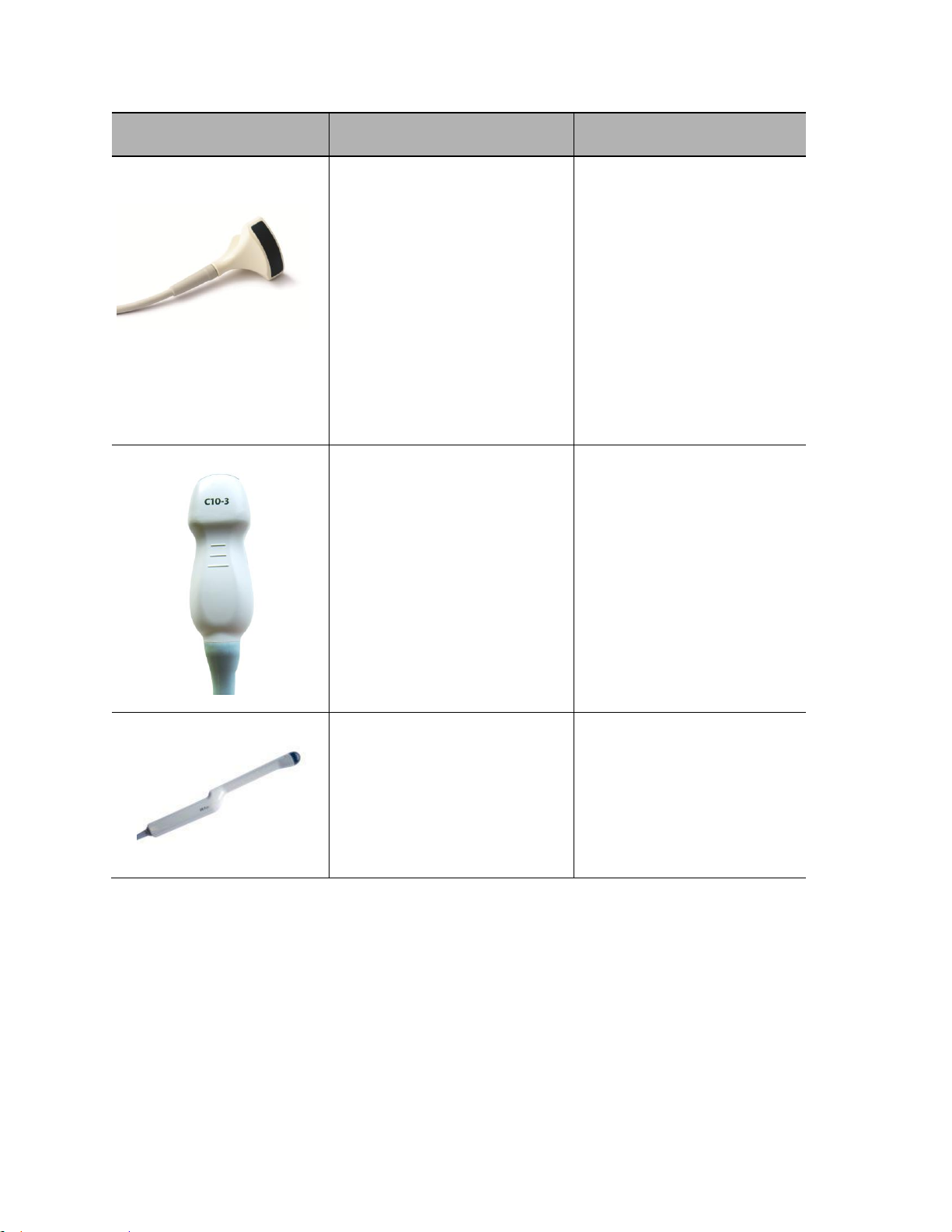
C10-3 X X
X
L14-5w X X
X
L14-5sp
X X X
L10-5 X X
X
L20-5 X L8-3 X X
X
E9-3 3D X
E9-3 X X
X
E9-4 X X
X
P4-1c X X
X
P8-3TEE
X X X
P9-3ic X
Note (*): The availability of options may be limited based on country or region of use.
Available with the system are one or more ZONARE Curvilinear, Endocavity, Linear, or Phased
array transducers allowing for many clinical applications. Accessories include, but are not
limited to the ZONARE ZPAK Battery and off-the-shelf components: bar code reader, foot pedal,
printers, biopsy guides, ECG cables and a wireless Ethernet interface. Case studies can be stored
to USB memory stick, DVD, and other industry standard archiving devices.
z.one
Instructions for Use, Q00350-00, Rev D 7 | P a g e
pro
Page 8
Instructions for Use
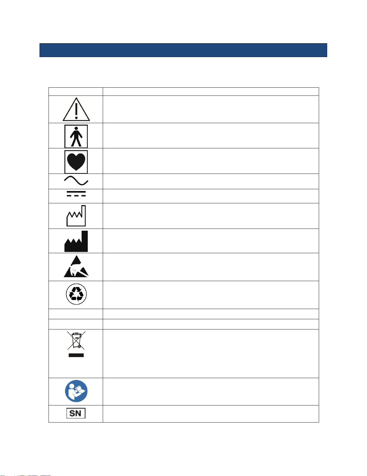
Symbol
Description
Information that may relate to safety of the patient, the operator, or the equipment
A type BF patient-applied part (B= body, F= floating applied part)
A type CF patient-applied part (C= cardiac, F= floating applied part)
Alternating current (AC)
Direct current (DC)
Date of manufacture
Manufacturer
Caution: ESD sensitive
Recyclable material
V
Voltage
Hz
Cycles per second
Waste Electrical & Electronic Equipment Standard
Applies to EU Member States only: this system should not be treated as household
waste.
ZONARE meets the WEEE Standard. For more information on returning or recycling this
system, please contact ZONARE Inc. or the distributor from whom you purchased the
system.
Consult the Instructions for Use
ZONARE serial number
Key to Symbols
The following symbols may be used in this document or elsewhere in product labeling.
z.one
Instructions for Use, Q00350-00, Rev D 8 | P a g e
pro
Page 9
Instructions for Use
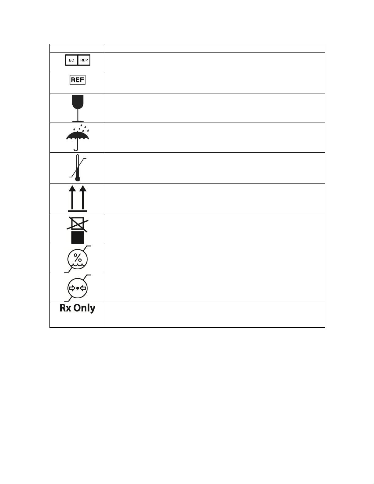
Symbol
Description
Authorized representative in the European Community
Catalog number
Shipping & Storage: Fragile
Shipping & Storage: Keep dry
Shipping & Storage: Temperature limits
Shipping & Storage: This side UP
Shipping& Storage: Do not stack above this container
Shipping & Storage: Humidity limits
Shipping & Storage: Pressure limits
Federal law restricts this device to sale by or on the order of a licensed healthcare
practitioner (USA).
z.one
Instructions for Use, Q00350-00, Rev D 9 | P a g e
pro
Page 10

Instructions for Use
This page left intentionally blank.
z.one
Instructions for Use, Q00350-00, Rev D 10 | P a g e
pro
Page 11
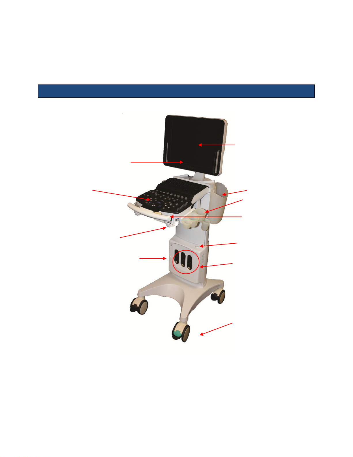
2. Getting Started
Speakers
User Interface
Gel Bottle Holder
Multi-Transducer
Port (MTP)
Power button
Control Panel
height adjust
17 inch display
Front Wheels
(swivel lock orientation)
Storage Bins
Cable
management
hooks
2 USB Ports
Instructions for Use
Please read this document carefully before using the z.one
Overview of Console, System and Features
ultrasound system.
pro
z.one
Figure 2.1: z.one
Instructions for Use, Q00350-00, Rev D 11 | P a g e
pro
System Components
pro
Page 12

LCD Display
Instructions for Use
The z.one
17-inch LCD Display shows the ultrasound image, plus patient and imaging
pro
information in designated areas of the screen.
Overall screen display = 1280 x 1024 pixels
Imaging area = 800 x 600 pixels
Full Screen Image Display
The z.one
allows you to enlarge the imaging portion of the monitor to use the full (1280 x
pro
1024) display. You can easily go from the imaging portion display of (800 x 600) to (1280 x
1024) with the push of a Function Key.
Video Adjustment
An on-screen set-up menu provide access to all video adjustment options.
Control Panel
The z.one
has a full –featured control panel/ user interface (see Quick Start Guide below).
pro
Multi-Transducer Port
The multi-transducer port (MTP) allows up to three transducers simultaneously connect to the
system. You can easily activate any of the transducers connected to the cart.
Transducer Holders
The safe storage for ZONARE transducers is provided on both sides of the z.one
system
pro
(Figure 2.1).
Internal Cart Hard Drive (Cart HD)
All current exam images are initially captured and archived to the hard drive. This data can be
automatically saved to the internal hard drive (cart HD), transferred using the Export function, or
retrieved from the drive using the Import function. The minimum size of the internal hard drive
is 120 GB.
NOTE: The internal hard drive is not intended for use as a long-term archive. Back up exam and
other data on the hard drive regularly.
z.one
Instructions for Use, Q00350-00, Rev D 12 | P a g e
pro
Page 13

Instructions for Use
CD/DVD Burner
The built-in CD/DVD burner allows you to import/ export exams from the system. Note: Before
deleting any exam data from the cart hard drive, always verify that data was successfully
transferred to the CD/DVD by viewing it on an external reader/ player.
When exams are exported onto the CD/DVD, a DICOM viewer program (Showcase®) and its
user’s manual are simultaneously exported onto the CD/DVD, allowing the exams to be opened,
annotated, and saved in several formats on any commercial PC.
Barcode Reader (option)
Patient accession numbers or patient ID numbers can be entered via a selection of ZONAREapproved barcode readers that can connect to a system USB port.
Foot Pedal (option)
A remote 2-pedal footswitch is optionally available for connection to the system via any
available USB port. The left pedal activates Freeze and the right pedal activates Store.
Backup ZPak Battery (option)
A backup battery may be ordered that can power the system for up to 1 ½ hours of normal use
in the absence of a connection to an active AC power outlet, depending on usage. The battery
allows the system to be operated in normal use without connection to an active AC Power
outlet.
The backup is mounted at the base of the system and is automatically kept charged by the DC
power suppliers within the system. The battery is charged (as needed) whenever the z.one
pro
system is connected to active AC power.
Printers and Other Peripherals
ZONARE offers a number of optional medical-grade (IEC 60601 compliant) peripherals. Detailed
instructions, for proper peripheral use, are covered in the manufacturer’s instructions provided
at the time of shipment.
z.one
Instructions for Use, Q00350-00, Rev D 13 | P a g e
pro
Page 14
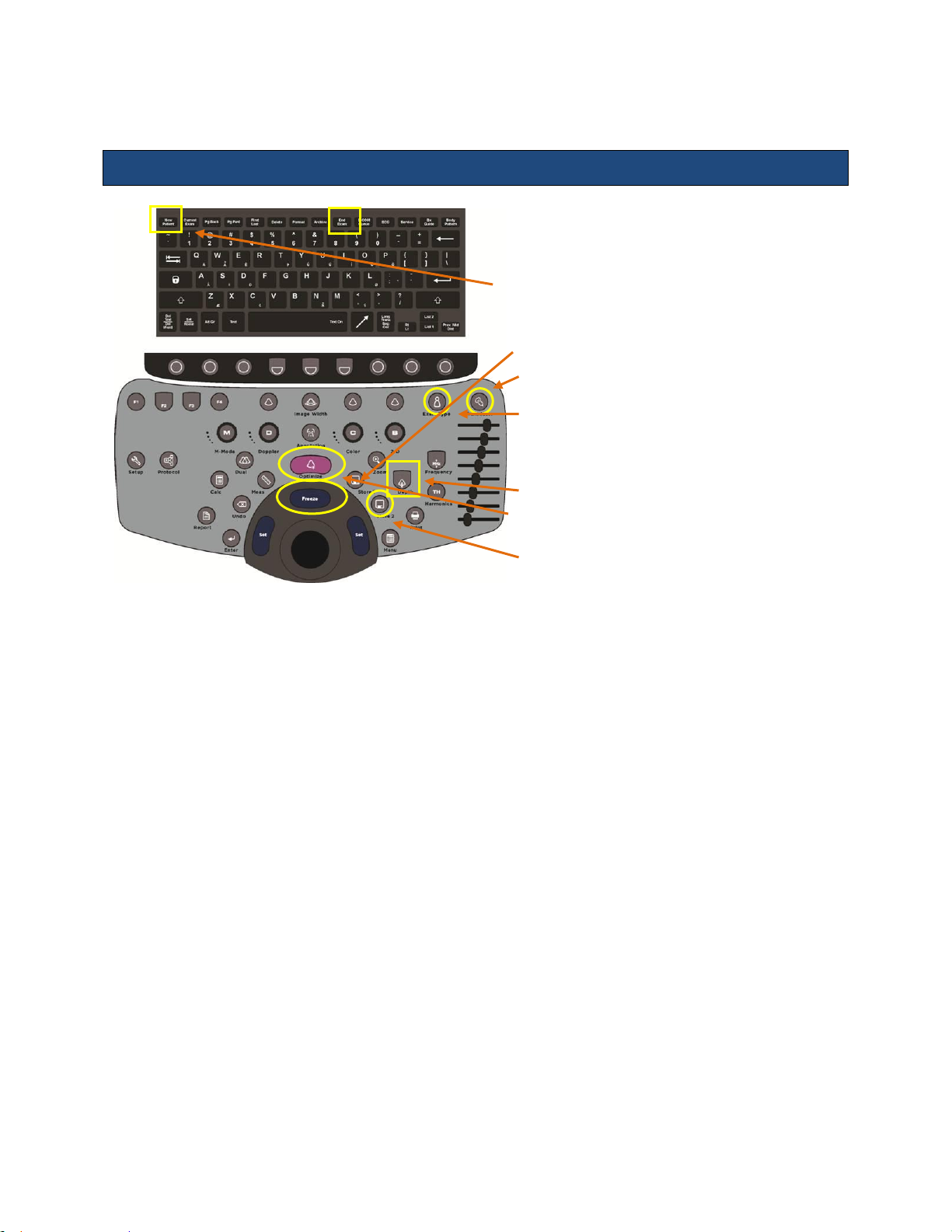
1. Connect transducer(s) (cable point up).
2. Press On button (above-right of transducer connectors).
3. Press New Patient
4. Enter patient information and select Exam/Pres on this
screen.
5. Press Freeze to begin imaging.
6. Press Transducer to display softkeys. Press softkey for
desired transducer.
7. Press Exam Type, then select softkey for desired
exam/preset.
8. Begin scanning and acquire desired image.
9. Adjust Depth.
10. Press Optimize to provide best image automatically.
11. Press Freeze to stop live scanning.
12. Use Store/Print to capture images/clips.
Quick Start Guide – Full Featured User Interface
Instructions for Use
Figure 2.2: z.one
Powering On/Off
1. Press and release the Power button to turn the system on. The system takes approximately
30 seconds to complete the normal power on sequence.
2. Check the z.one
display to ensure the ZONARE startup screen is shown. When initialization is
pro
complete, the system is ready for imaging.
3. To Power Off press and release the Power button. NOTE: When servicing the z.one
always be sure to turn the circuit breaker to the Off position.
Basic Measurements (Meas Button)
1. Press Meas while image is frozen.
2. Select desired measurement on menu & press Set.
3. Position first caliper with Trackball & press Set.
4. Position second caliper with Trackball & press Set.
Basic Calculations (Calc Button)
1. Press Calc while image is frozen.
2. Select desired calc on menu & press Set.
z.one
Instructions for Use, Q00350-00, Rev D 14 | P a g e
pro
Control Panel
pro
system,
pro
Page 15

Instructions for Use
3. Position caliper with Trackball & press Set.
4. Position additional caliper(s) with Trackball & press Set. Calc will display on screen.
5. Press Enter or Store to store the result.
6. Press Report to display calcs you’ve recorded.
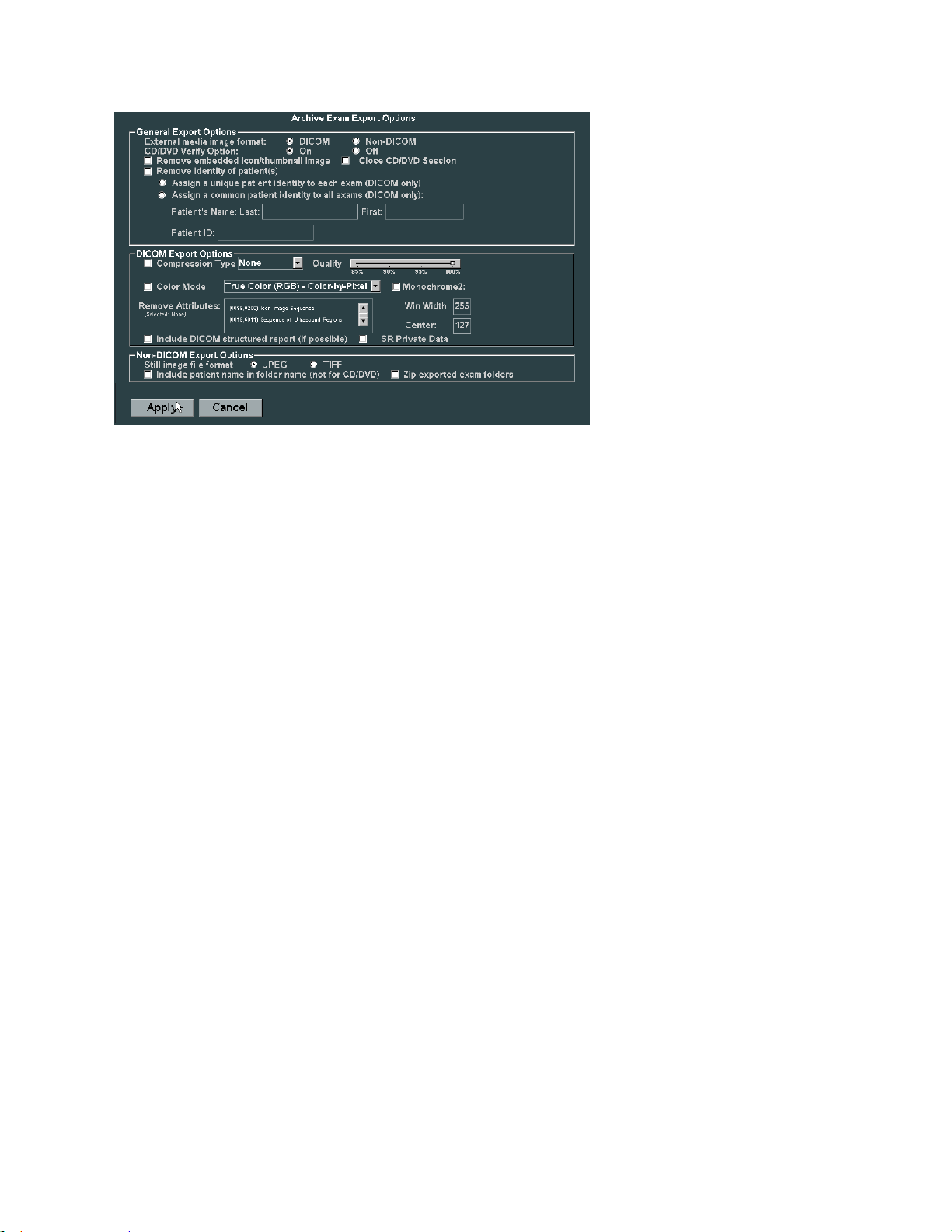
Export Exams to USB or CD/DVD
1. Press Archive (back row of QWERTY keyboard).
2. Point to Export. This will open Archive Exam Export.
3. Point to Destination. Then click Export at bottom of screen.
4. On next screen, click Options. Archive Exam Export Options screen displays:
5. Select Non-DICOM. Select JPEG or TIFF.
6. Click Apply.
7. Click Export on next screen. Verify export (Yes/No) at prompt.
If Yes, exam exports to USB/CD/DVD but is not deleted from hard drive.
Review Images in Current Exam
1. Press Current Exam (back row of QWERTY keyboard).
2. All stored images for exam appear.
3. To view an image in large format, point with cursor and press Set key.
4. Press Current Exam to exit review & return to live imaging.
z.one
Instructions for Use, Q00350-00, Rev D 15 | P a g e
pro
Page 16
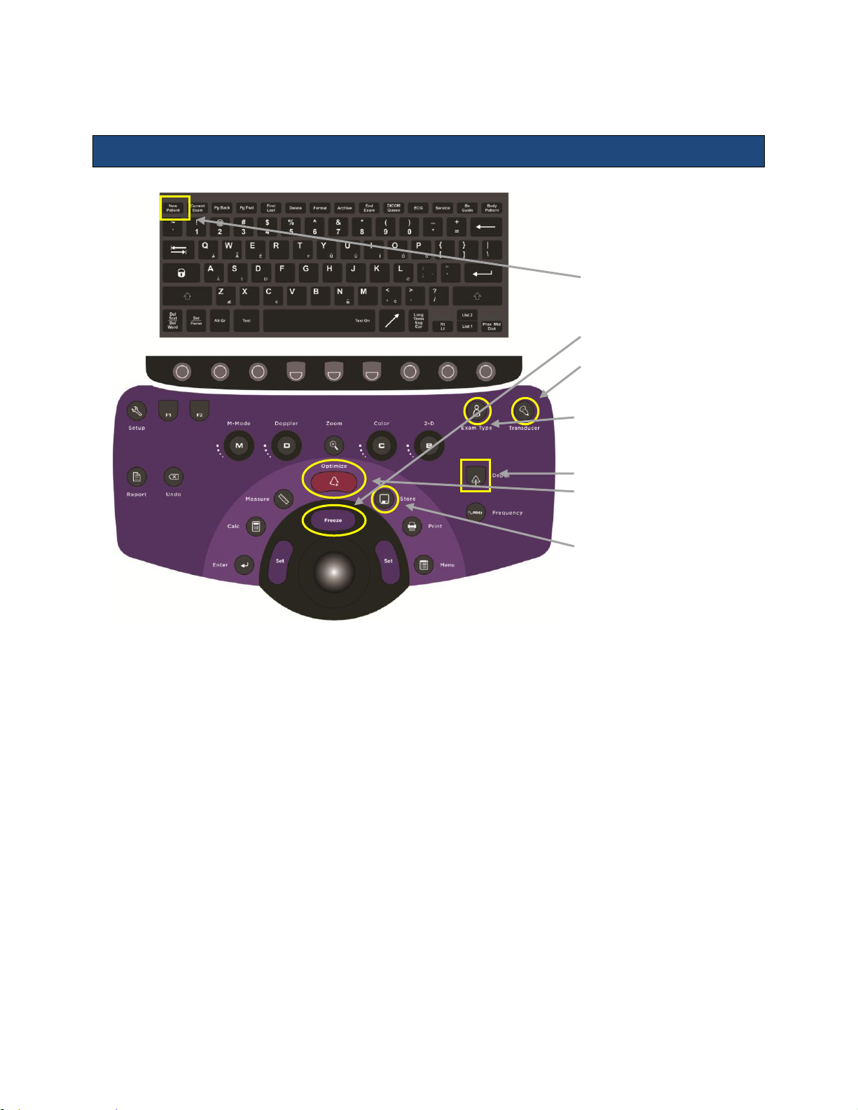
1. Connect transducer(s) with
cable pointing up
2. Press ON button (aboveright of transducer
connectors)
3. Press New Patient
4. Enter patient information
and select Exam/Preset
on screen
5. Press Freeze to begin
imaging
6. Press Transducer key to
display softkeys. Press
softkey for desired
transducer
7. Press Exam Type, then
select softkey for desired
exam / preset
8. Begin scanning and
acquire desired image.
9. Adjust Depth toggle key
10. Press Optimize button to
provide best image
automatically
11. Press Freeze button to
stop live scanning
12. Use Store or Print
buttons to capture images
or clips
13. Press End Exam to close
study
Quick Start Guide – Special Procedures User Interface
Instructions for Use
z.one
Instructions for Use, Q00350-00, Rev D 16 | P a g e
pro
Figure 2.3: z.one
SP Control Panel
pro
Page 17

Instructions for Use
Powering On/Off
1. Press and release the Power button to turn the system on. The system takes approximately
30 seconds to complete the normal power on sequence.
2. Check the z.one
display to ensure the ZONARE startup screen is shown. When initialization is
pro
complete, the system is ready for imaging.
3. To Power Off press and release the Power button. NOTE: When servicing the z.one
system,
pro
always be sure to turn the circuit breaker to the Off position.
Basic Measurements (Meas Button)
Depth (cm)
1. During live 2D scanning, press Measure.
2. Position caliper with Trackball.
3. Depth will display on screen.
Distance (cm)
1. Press Measure while 2D or M-Mode image is frozen.
2. Select Distance on menu & press Set.
3. Position first caliper with Trackball & press Set.
4. Position second caliper with Trackball & press Set.
5. Distance between calipers will display on screen.
Basic Calculations (Calc Button)
1. Press Calc while image is frozen.
2. Select desired calc on menu & press Set.
3. Position caliper with Trackball & press Set.
4. Position additional caliper(s) with Trackball & press Set. Calc will display on screen.
5. Press Enter or Store to store the result.
6. Press Report to display calcs you’ve recorded.
Export Exams to USB or CD/DVD
1. Press Archive (back row of QWERTY keyboard).
2. Point to Export. This will open Archive Exam Export.
3. Point to Destination. Then click Export at bottom of screen.
4. On next screen, click Options. Archive Exam Export Options screen displays:
z.one
Instructions for Use, Q00350-00, Rev D 17 | P a g e
pro
Page 18
5. Select Non-DICOM. Select JPEG or TIFF.
6. Click Apply.
7. Click Export on next screen. Verify export (Yes/No) at prompt.
If Yes, exam exports to USB/CD/DVD but is not deleted from hard drive.
Review Images in Current Exam
1. Press Current Exam (back row of QWERTY keyboard).
3. All stored images for exam appear.
3. To view an image in large format, point with cursor and press Set key.
4. Press Current Exam to exit review & return to live imaging.
Instructions for Use
Restart Closed Exam
1. Press New Patient (QWERTY keyboard).
2. Click Restart (bottom of screen).
3. Point cursor to desired exam and press Set key.
4. Click Select Exam (bottom of screen). Next, press Exit on patient form.
5. You can now resume exam & add images to the study.
6. Press End Exam (QWERTY keyboard) to end exam.
Delete Exams from Archive
NOTE: System has limited memory; delete/transfer exams weekly.
1. Press Archive (QWERTY keyboard).
2. Point cursor to desired exam & press Set key.
Click Delete (bottom of screen). Select Yes to confirm. Exam is deleted from hard drive.
z.one
Instructions for Use, Q00350-00, Rev D 18 | P a g e
pro
Page 19
Instructions for Use
1. Lower the adjustable height to MINIMUM using the height adjustment release lever.
2. Fold the monitor display down to a horizontal position and lock in place. The monitor arm
will lock into a non-rotating position when the two parts of the articulating arm are in-line
with each other AND centered with the system.
3. Ensure that the transducer cables are wrapped over the cable hooks.
4. Place the front wheels in the non-swivel position.
5. Ensure that all wheels are unlocked, and push the cart from the front when transferring from
location to location.
6. When moving the cart over obstacles, always pull from the front.
Release lever
Moving the z.one
system
pro
When Moving
When Scanning
1. Before scanning a patient, apply the brake by fully depressing the brake pedal on each front wheel.
2. To disengage brakes, flip up the pedals.
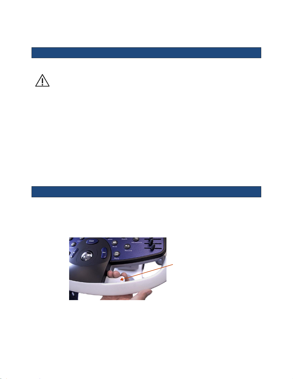
Height adjustment
The height of the user interface console can be adjusted by squeezing the release lever located
inside the right-front handle. Refer to Figure 2.4: Height Adjustment
Figure 2.4: Height Adjustment
z.one
Instructions for Use, Q00350-00, Rev D 19 | P a g e
pro
Page 20
3. Imaging (Mode Controls)
Control
Description/Use
* Indicates this control is also available in retrospective processing.
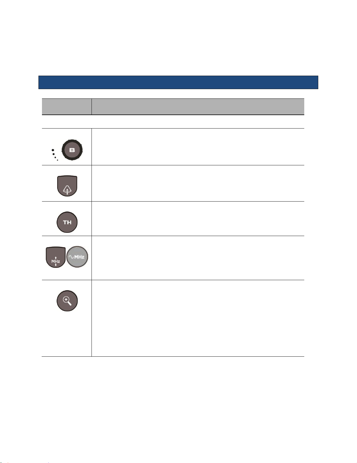
Gain*
Adjust Gain by rotating the outer ring of the B-Mode (2D) button.
Depth
Press the Depth button UP to decrease depth; press DOWN to increase depth.
Harmonics
Press the TH button to toggle on/off tissue harmonic imaging. Hard key not available
on the Special Procedures interface.
Frequency
Press the Frequency button UP to increase transmit frequency; press DOWN to decrease
transmit frequency. On the Special Procedures interface, repeated pressing of the
push button cycles through the frequency options.
NOTE: Press Frequency up or down when doing compound imaging to cycle through
Frequency and Compounding choices.
Zoom
Acoustic Zoom (live image).
The first press displays a Region Of Interest (ROI) that can be positioned/size over the
anatomy of interest.
The second press zooms the ROI, reconfiguring the scanner to provide enhanced
imaging in that region.
Display Zoom (Frozen/Cine image)
The first press zooms the image.
The Depth key changes the magnification.
The Trackball pans the image.
2D/B-Mode Controls
Instructions for Use
z.one
Instructions for Use, Q00350-00, Rev D 20 | P a g e
pro
Page 21
Instructions for Use
Control
Description/Use
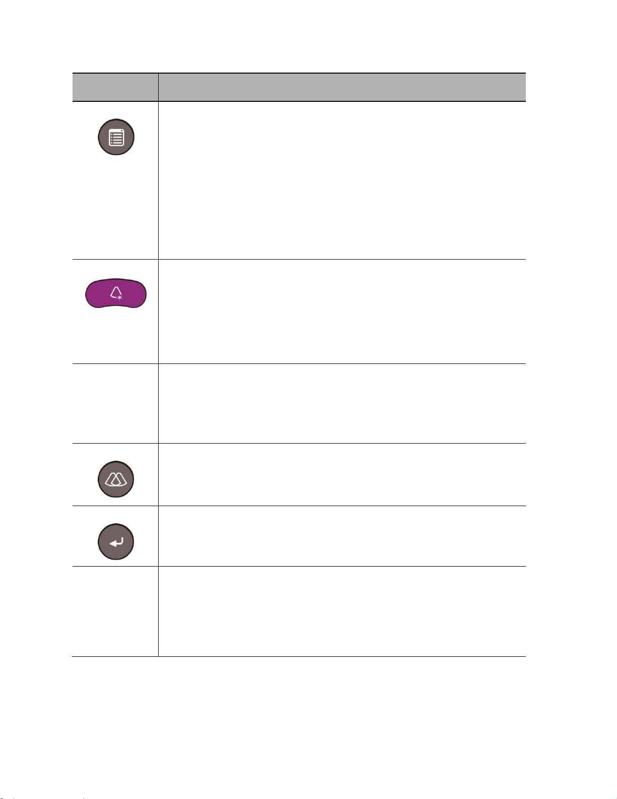
Menu
While B-mode is active the Menu button invokes a pop-up menu showing many
secondary optimization controls including:
Maps*
Tint*
Dynamic Range*
L/R invert*
U/D invert*
Persistence*
Edge*
Acoustic Output
Optimize*
Overall/DGC gain: Press the Optimize button to automatically balance the overall/DGC
gain. The B-Mode image adjusts the brightness of the image to the default target gain
value.
Sound speed correction: Press and hold down Optimize to automatically compensate
for the sound speed in tissue. The B-Mode image pauses momentarily, then adjusts for
the detected sound speed.
To exit optimize mode: Double-click Optimize to turn optimize functions off.
B Steer
NOTE: For linear array transducers only
n Turn B Steer softkey to select B Steer (0°); B Steer 10 (10° right); or B Steer –10 (10°
left).
NOTE: L8-3 transducer B Steer options: B Steer (0°), B Steer 15 (15° right), B Steer –15
(15° left).
Dual: OFF/ON
Press the Dual mode button to toggle the Dual imaging function on/off. Hard key not
available on the Special Procedures interface.
NOTE: The Dual imaging function allows for displaying two separate images on the
screen (at the same time) for concurrent comparison/analysis.
Dual: Toggle
Press the Enter button to change the selection of the active/selected image (left or right
image, as displayed on screen). Hard key Toggle not available on the Special
Procedures interface.
Simul: (Dual)
Press the softkey assigned to Simul to toggle on/off the simultaneous dual imaging
update modality.
NOTE: When simul dual is active, the two different images, potentially using different
modalities (i.e., color Doppler and power Doppler) are dynamically updated,
simultaneously. When this function is deselected (standard dual mode) one image is static,
while the other image is dynamically active.
z.one
Instructions for Use, Q00350-00, Rev D 21 | P a g e
pro
Page 22
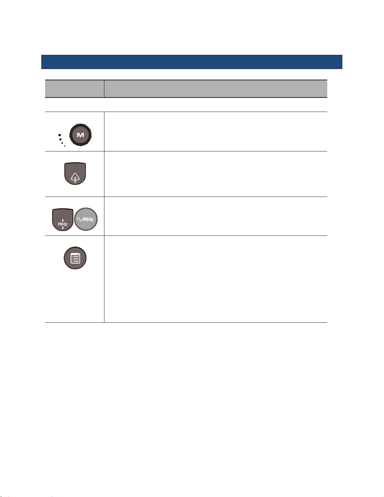
M Control
Description/Use
* Indicates this control is also available in retrospective processing.
Gain*
Rotate outer ring of the M-Mode button to adjust gain.
Depth
Press the Depth rocker button UP to decrease depth; press DOWN button to increase
depth.
Frequency
Press the Frequency button to cycle through the transmit frequency choices. The
selected value is displayed in the Image Information area. On the Special Procedures
interface, repeated pressing of the push button cycles through the frequency
options.
Menu
While M-mode is active the Menu button invokes a pop-up menu showing many
secondary optimization controls including:
Display Format (full size and split-screen)*
Sweep Speed*
Maps*
Tint*
Dynamic Range*
Persistence*
Acoustic Output
M-Mode Controls
Instructions for Use
z.one
Instructions for Use, Q00350-00, Rev D 22 | P a g e
pro
Page 23
Color Doppler/Power Doppler Mode Controls
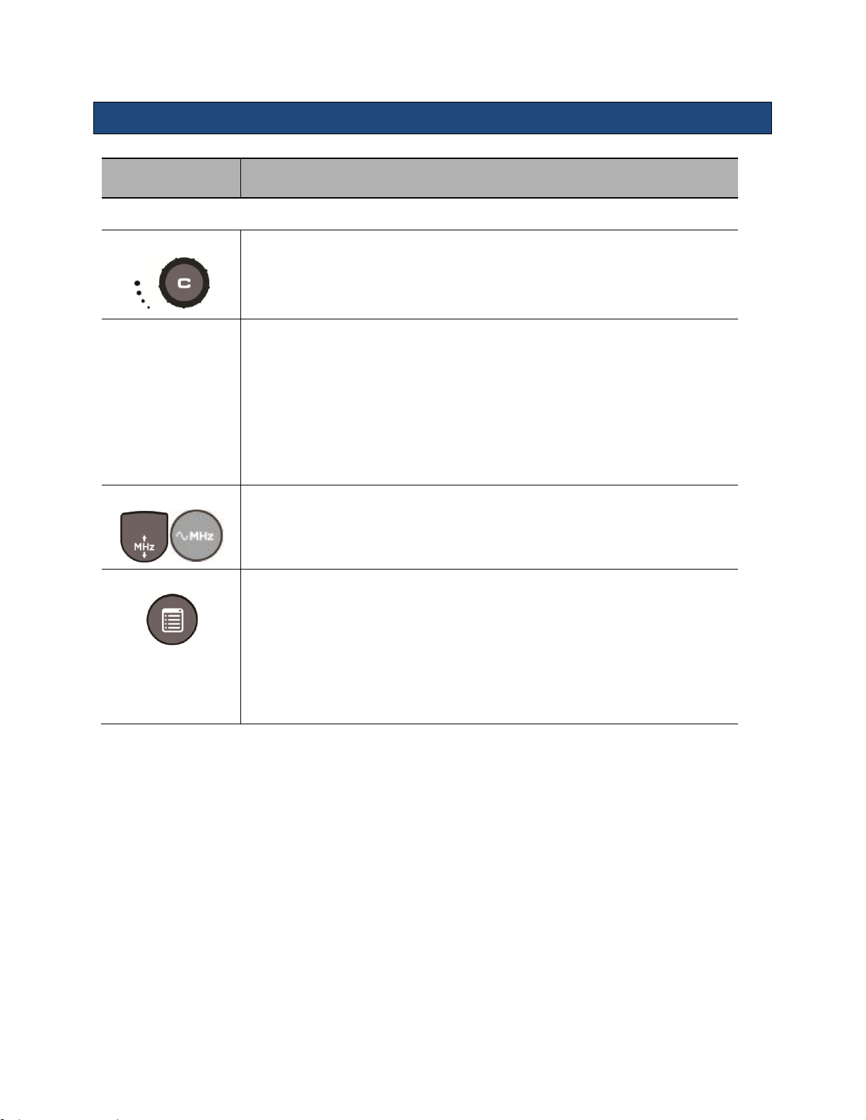
CD/PD Control
Description/Use
* Indicates that this control is also available in retrospective processing
Gain*
Adjust Gain by rotating the outer ring of the C-Mode button.
Softkeys
While Color Doppler is active the Softkeys at the back of the console shows many
optimization controls including:
Steer (Linear transducers only)
Invert*
Filter*
Scale
Baseline*
Power/Velocity Doppler
Frequency
Press the Frequency button to cycle through the transmit frequency choices. On the
Special Procedures interface, repeated pressing of the push button cycles
through the frequency options.
Menu
While Color Doppler is active the Menu button invokes a pop-up menu showing many
secondary optimization controls including:
Maps*
Flash Cancelation
Persistence*
Edge*
Acoustic Output
Instructions for Use
z.one
Instructions for Use, Q00350-00, Rev D 23 | P a g e
pro
Page 24
Instructions for Use
Doppler Control
Description/Use
* Indicates that this control is also available in retrospective processing.
Gain*
Adjust Gain by rotating the outer ring of the D-Mode button.
Softkeys
While PW Doppler is active the Softkeys at the back of the console shows many
optimization controls including:
Update:
o Update On: Only the B-mode or the Doppler strip is active, not
both. Pressing the select key toggles which is active.
o Update Off: B-mode and Doppler strip are active simultaneously.
Filter*
Invert*
Gate Size
Baseline*
Angle*
o Turning the knob changes the angle correct in 1-degree
increments.
o Pressing the knob snaps the angle correct to (-60-0-60
º)
Volume
Steer (Linear transducers only)
o Turning the knob changes the steer in 1-degree increments.
Pressing the knob snaps the steer to preset angles. If CD is active then its
steer angle snaps to align.
PW/CW: See CW and Echocardiography section
Menu
While strip Doppler is active the Menu button invokes a pop-up menu showing
many secondary optimization controls including:
Gate Size
Dynamic Range*
Sweep Speed*
Display Format(full size and split-screen)*
Maps*
Tint*
Acoustic Output
Strip Doppler Mode Controls (Pulsed Wave and Continuous Wave)
Note: Continuous Wave Doppler imaging is available only on z.one
Echocardiology or Advanced Vascular Options.
system equipped with the
pro
There are two mechanisms to invoke CW:
z.one
Instructions for Use, Q00350-00, Rev D 24 | P a g e
pro
Page 25
Instructions for Use
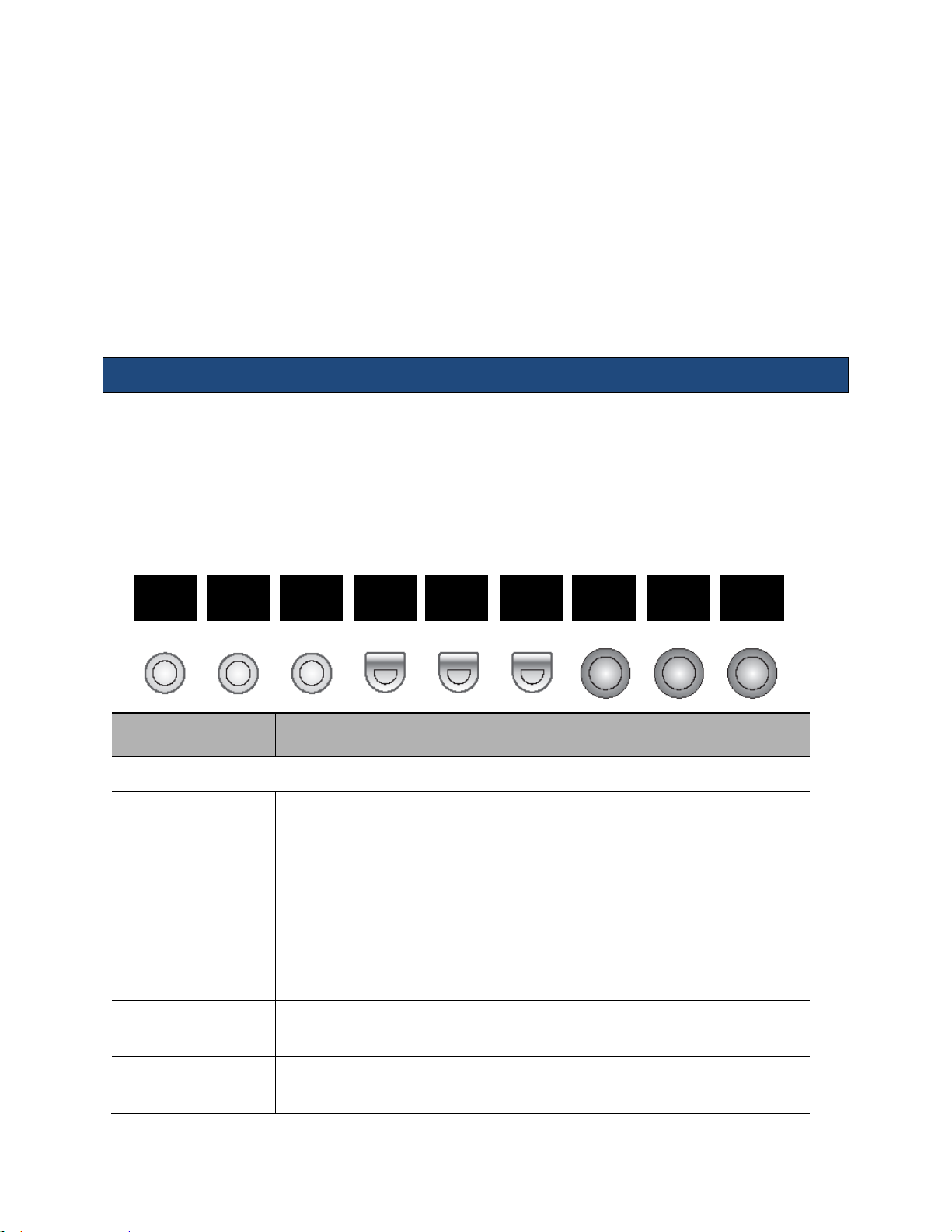
Physio Control
Description/Use
* Indicates that this control is also available in retrospective processing.
Exit
Exits the ECG control function without changing the traces.
ECG
Enables or disable the ECG trace
Resp
Enables or disables the Respiratory trace. ECG must be active for the Respiratory
trace to be active.
Sweep
Changes the sweep speed of the traces in 2D and Color. This control does not apply
during strip imaging modes.
ECG Size/ Pos
Pressing this knob toggles between controlling the position and size of the ECG
trace. Turning the knob changes the position or size.
Resp Size/ Pos
Pressing this knob toggles between controlling the position and size of the Resp
trace. Turning the knob changes the position or size.
Exit
ECG
Resp
Sweep
ECG
Size/Pos
Resp
Size/Pos
It can be assigned to a Programmable Mode Key in System setup -> Keys. When invoked this
way the programmable mode key acts as a CW hard key and the “D” mode button is dedicated to
PW.
It can have shared access with PW through the “D” mode button. When invoked, the default
Doppler mode is determined by preset. While strip Doppler is active the right-most soft key
toggles between PW and CW. Subsequent invocations of strip Doppler invoke the last used
Doppler mode.
The optimization controls available in CW are generally the same as in PW. See the Strip
Doppler section (above) for details.
Physio Controls
The Echocardiography Option includes a physio module that supports ECG and respiratory
traces. The ECG must be active to enable respiratory. Presets determine if EGG or both traces
are on by default. The physio traces can be enabled/disabled and controlled through the “ECG”
key in the top row of the keyboard. When the ECG function is invoked the following softkeys are
displayed:
z.one
Instructions for Use, Q00350-00, Rev D 25 | P a g e
pro
Page 26

Instructions for Use
NOTE: ZONARE recommends the following ECG patient cables and lead wires from Advantage
Medical Cables (AMC) (www.advantagemed.com):
AMC LW-3700024/3I (International patient lead wire replacements)
AMC LW-3700024/3A (Domestic patient lead wire replacements)
AMC CB-83340 (ECG trunk cable)
AMC CB-33598-00 (Accessory cable for use without lead wires)
Contrast, Elastography & 3D/4D (Options)
Refer to Section 7: Advance Features for details on Contrast and Elastography. Refer to Section
8 for information related to 3D/ 4D Imaging.
z.one
Instructions for Use, Q00350-00, Rev D 26 | P a g e
pro
Page 27
Instructions for Use
Refer to ZONARE’s Transducers Cleaning and Disinfection, Q00066, for directions,
cautions and warnings associated with the care and maintenance of ZONARE
transducers.
Always examine transducers for damage, such as cracks, splitting, holes, or fluid leaks. If
damage is evident, discontinue use of the transducer and contact ZONARE.
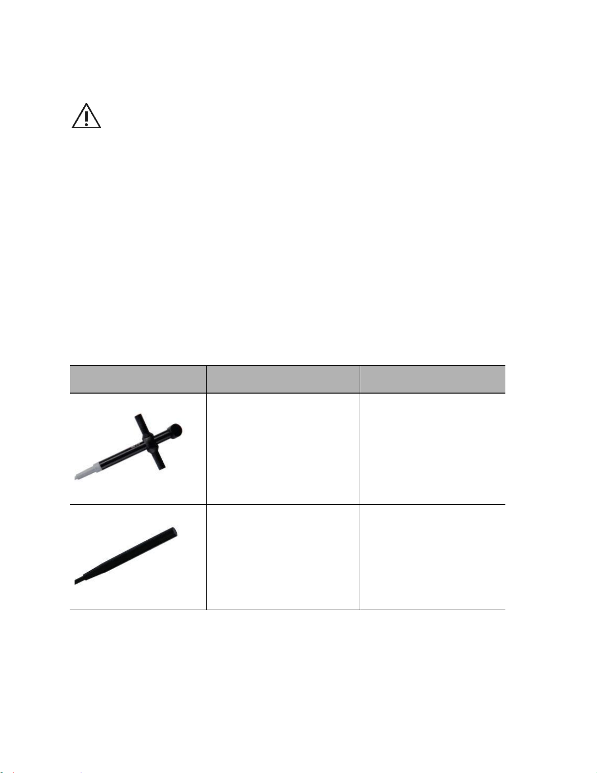
Transducer
Applications
Biopsy Guide
A2CW
Cardiac, Adult
Cardiac, Pediatric
Pediatric
No
A5CW
Pediatric
Peripheral Vascular
No
4. Transducers
The following ZONARE transducers may be available for use with the z.one
system.
NOTE(1): The z.one
Ultrasound System is designed for compatibility with the following
pro
transducers. Because the availability of transducers is subject to government regulation and
approval, some items included in the table may not be commercially marketed nor made available
in your region of use.
NOTE(2): Once approved in accordance with local government regulation, access to transducers is
further controlled by individual transducer licensing as determined by purchased system
configuration.
ultrasound
pro
z.one
Instructions for Use, Q00350-00, Rev D 27 | P a g e
pro
Page 28
Instructions for Use
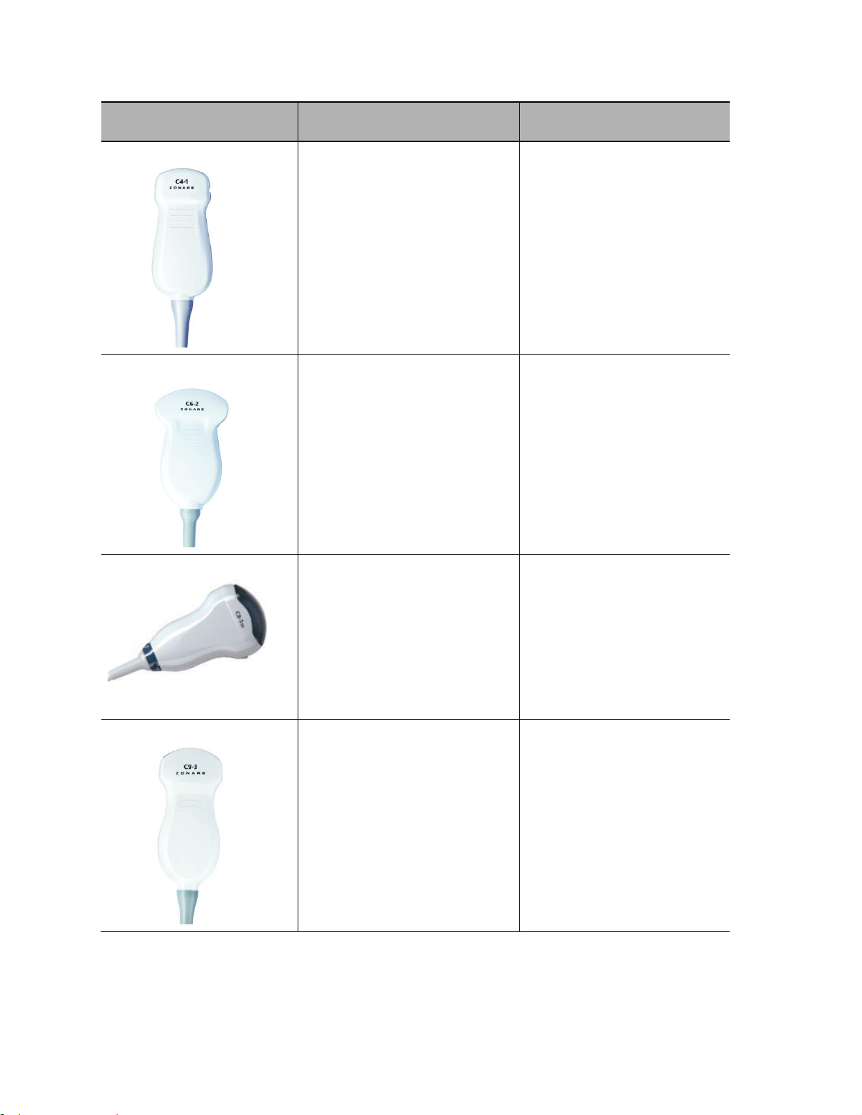
Transducer
Applications
Biopsy Guide
C4-1
Abdominal (includes renal,
GYN/Pelvic)
Cardiac, Adult
Contrast
Fetal
Musculo-skel (conventional)
Pediatric
Yes
CIVCO Infiniti™ Needle Guidance
System
#698-013
C6-2
Abdominal (includes renal,
GYN/Pelvic)
Contrast
Fetal
Pediatric
Peripheral Vascular
Yes
CIVCO Ultra-Pro II™ Needle
Guidance System
#698-003
C8-33D
Abdominal (includes renal,
GYN/Pelvic)
Fetal
Pediatric
Peripheral Vascular
3D/4D
No
C9-3
Abdominal (includes renal,
GYN/Pelvic)
Contrast
Fetal
Intra-operative (abdominal)
Intra-operative (vascular)
Musculo-skel (conventional)
Musculo-skel (Superficial)
Pediatric
Peripheral Vascular
Yes
CIVCO Infiniti Needle Guidance
System
#698-009
z.one
Instructions for Use, Q00350-00, Rev D 28 | P a g e
pro
Page 29
Instructions for Use
Transducer
Applications
Biopsy Guide
C9-3sp
Abdominal (includes renal,
GYN/Pelvic)
Contrast
Fetal
Intraoperative (Neuro, abdominal,
thoracic (cardiac) and vascular (PV))
Musculo-skel (conventional)
Musculo-skel (Superficial)
Neonatal Cephalic
Pediatric
Peripheral Vascular
Small Organ (Thyroid, Breast, Testes,
etc)
No
C10-3
Abdominal (includes renal,
GYN/Pelvic)
Adult Cephalic/ trans-cranial
Cardiac, Adult
Cardiac, Pediatric
Fetal
Intra-operative (Neuro, abdominal,
thoracic (cardiac) and vascular (PV))
Neonatal Cephalic
Pediatric
Peripheral vascular
No
E9-33D
Fetal
Trans-rectal
Trans-vaginal
3D/4D
No
z.one
pro
Instructions for Use, Q00350-00, Rev D 29 | P a g e
Page 30

Instructions for Use
Transducer
Applications
Biopsy Guide
E9-3
Fetal
Trans-rectal
Trans-vaginal
Yes
ZONARE Reusable Endocavity
Needle Guidance System
#Z168-00
ZONARE Disposable Endocavity
Needle Guidance System
#Z169-00
E9-4
Fetal
Trans-rectal
Trans-vaginal
Yes
CIVCO Disposable Transvaginal
Needle Guidance System
#698-010, #698-011, #698-014
CIVCO Reusable Endocavity Needle
Guidance System
#698-002
L8-3
Fetal
Abdominal (includes renal,
GYN/Pelvic)
Intra-operative (Neuro, abdominal,
thoracic (cardiac) and vascular (PV))
Pediatric
Small Organ (Thyroid, Breast, Testes,
etc)
Musculo-skel (Conventional)
Musculo-skel (Superficial)
Peripheral Vascular
Yes
CIVCO AccuSITE™ Needle Guidance
System
#698-005
z.one
Instructions for Use, Q00350-00, Rev D 30 | P a g e
pro
Page 31
Instructions for Use
Transducer
Applications
Biopsy Guide
L14-5sp
Abdominal (includes renal,
GYN/Pelvic)
Fetal
Intraoperative (Neuro, abdominal,
thoracic (cardiac) and vascular (PV))
Musculo-skel (conventional)
Musculo-skel (superficial)
Neonatal Cephalic
Pediatric
Peripheral Vascular
Small Organ (Thyroid, Breast, Testes,
etc)
Yes
CIVCO AccuSITE™ Needle Guidance
System
#698-006
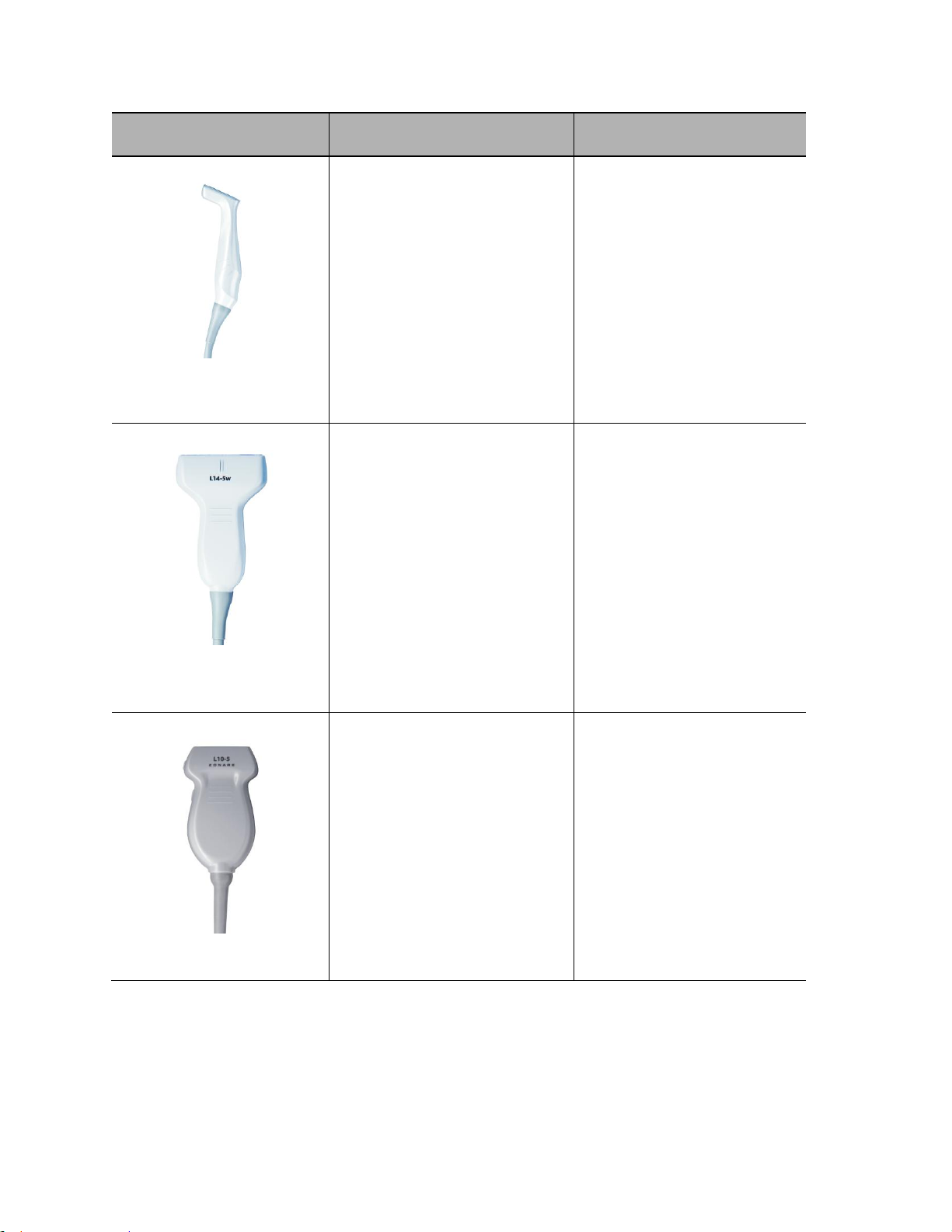
L14-5w
Abdominal (includes renal,
GYN/Pelvic)
Contrast
Fetal
Intraoperative (Neuro, abdominal,
thoracic (cardiac) and vascular (PV))
Musculo-skel (conventional)
Musculo-skel (superficial)
Neonatal Cephalic
Pediatric
Peripheral Vascular
Small Organ (Thyroid, Breast, Testes,
etc)
Yes
CIVCO AccuSITE™ Needle Guidance
System
#698-012
CIVCO Infiniti™ Needle Guidance
System
#698-007
L10-5
Abdominal (includes renal,
GYN/Pelvic)
Fetal
Intraoperative (Neuro, abdominal,
thoracic (cardiac) and vascular (PV))
Musculo-skel (conventional)
Musculo-skel (superficial)
Neonatal Cephalic
Pediatric
Peripheral Vascular
Small Organ (Thyroid, Breast, Testes,
etc)
Yes
CIVCO Infiniti Plus™ Needle
Guidance System
#698-015
CIVCO Ultra Pro™ Needle Guidance
System
#698-004
CIVCO AccuSITE ™ Needle
Guidance System
#698-008
z.one
Instructions for Use, Q00350-00, Rev D 31 | P a g e
pro
Page 32

Instructions for Use
Transducer
Applications
Biopsy Guide
L20-5
Abdominal (includes renal,
GYN/Pelvic)
Contrast
Fetal
Intraoperative (Neuro, abdominal,
thoracic (cardiac) and vascular (PV))
Musculo-skel (conventional)
Musculo-skel (superficial)
Neonatal Cephalic
Pediatric
Peripheral Vascular
Small Organ (Thyroid, Breast, Testes,
etc)
No
P4-1c
Adult Cephalic/ Trans-cranial
Abdominal
Cardiac Adult
Cardiac Pediatric
Contrast
Fetal
Neonatal Cephalic
Pediatric
Peripheral Vascular
No
P8-3TEE
Transesophageal Echocardiography
(non-cardiac and cardiac)
No
P9-3ic
Intracardiac Echocardiography
No
z.one
Instructions for Use, Q00350-00, Rev D 32 | P a g e
pro
Page 33

Instructions for Use
Refer to TEE Transducer Care and Maintenance (Q00195) for instructions on inspecting,
cleaning, and maintaining the P8-3 TEE transducer.
TEE Transducer (P8-3TEE)
The z.one
Scan plane rotation is controlled by two push-buttons on the control handle and can be rotated
from 0° to 180°. The wheels on the handle of the transducer control the deflection of the tip. The
smaller lower wheel is used to control the transducer Left/Right tip deflection (see Figure below).
The larger wheel on top of the handle is used to control the transducer Anterior/Posterior tip
deflection. Both wheels have a friction lock and freely moving mode.
system will support TEE imaging when used with the P8-3 TEE transducer.
pro
Figure 4-1: TEE Transducer Handle
z.one
Instructions for Use, Q00350-00, Rev D 33 | P a g e
pro
Page 34

Instructions for Use
The TEE probe includes a sensor to monitor the temperature of the tip during use. While
imaging the following on-screen indicator is shown:
The angle of rotation shows the scan plane rotation while the temperature indicator shows the
temperature at the transducer face. This indicator can optionally be turned off if the
temperature is below 40.5ºC. Above that temperature the indicator will always be displayed. In
addition:
If the temperature reaches 41.5ºC the system will automatically freeze and display a warning
message. This warning message can be dismissed and imaging can continue. While operating at
this temperature is safe, close monitoring of the temperature is recommended. The temperature
indicator will show in yellow to indicate this.
If the temperature reaches 42.7ºC the system will automatically freeze imaging. The transducer
must be disconnected and allowed to cool off before additional imaging is supported.
z.one
Instructions for Use, Q00350-00, Rev D 34 | P a g e
pro
Page 35

Instructions for Use
Transducer
Abdomen
OB
GYN
Vascular
Cardiac
Small
Parts
Pediatrics
A2CW X
A5CW X
C4-1 X X X X
X
C6-2 X X X X
X
C8-33D X X X X
X
C9-3 X X X X
X
C9-3sp X X X
X
C10-3 X X X X X
X
L14-5w X X X
X
L14-5sp X X X
X
L10-5 X X X
X
L20-5 X X X X
X
L8-3 X X X
X
E9-33D X X
E9-3 X X
E9-4 X X
P4-1c X X X X X
X
P8-3TEE X
P9-3ic X
The z.one
organizes presets by transducer and by exam type. The exam type is a mechanism
pro
to filter the list of presets seen for any given transducer. The following table shows the exam
types supported for each transducer:
z.one
Instructions for Use, Q00350-00, Rev D 35 | P a g e
pro
Page 36

5. Measurements and Annotation
Generic measurements are accessed in all imaging modes by pressing the Meas button.
A subset of measurements is available in live imaging.
Most presets have specific pre-defined measurements, calculations and reports
associated with them. These are accessed by pressing the Calc button on a frozen/cine
image.
The Undo button will generally undo the last measurement action. For example, it can
be used to remove a caliper that had been accidentally invoked.
The Enter button will generally finalize the currently active measurement. For example,
within the calc package it will enter the current measurement into the report. Within
generic measurements it will lock the current measurement in place so that an additional
measurement can be invoked.
Measurements
Instructions for Use
B-Mode (2D)
Depth: Depth is the only 2D measurement available on a live image. On a live image pressing
the Meas button immediately invokes the Depth measurement.
Distance: Once Distance is selected from the Meas menu the first half of a caliper pair
appears. Pressing the set button locks that in place and the second half of that caliper
pair appears.
Circ/Area: Circumference and area measurements can be done with either a trace or ellipse.
The preferred tool can be configured in System SetupCalcsGeneral.
Volume: Volumes are supported with 3 linked caliper pair measurements. Press Enter after the
first caliper pair to invoke the second. The third pair is invoked after the image is
unfrozen and then frozen again.
z.one
Instructions for Use, Q00350-00, Rev D 36 | P a g e
pro
Page 37

Instructions for Use
M-Mode
Depth: Depth is the only M-mode measurement available on a live image. On a live image
pressing the Meas button immediately invokes the Depth measurement.
Distance: Once Distance is selected from the Meas menu the first half of a caliper pair
appears. Pressing the set button locks that in place and the second half of that caliper
pair appears.
HR: By default the HR measurement assumes that one beat is measured. The default
number of heart cycles can be changed in System SetupCalcsGeneral.
PW Doppler
Doppler measurements can be performed by either manual measurements or Auto-Trace
Auto-Trace
There are multiple ways of invoking auto-Trace. Any of the following may be used:
A function key can be configured for auto-Trace in System Setup->Keys.
Double-clicking on the Meas button while Doppler is active.
Selecting Auto-Trace from the Meas menu.
Once Auto-Trace is active the Meas menu can be used to select which result is displayed. Most
results require a Max waveform, which is displayed in green on the Doppler strip. TAMn and Vol
Flow require a Mean waveform, which is displayed in yellow on the Doppler strip.
On the live image the results update automatically. The number of heart cycles included in the
result can be configured in System SetupCalcsAuto-Dop.
Manual Measurements
Velocity: Velocity is the only Doppler measurement available on a live image. On a live image
pressing the Meas button immediately invokes the Velocity measurement.
Velocity Pairs, RI, Accl, S/D, A/B: These are selectable from the Meas menu while a frozen
Doppler strip is displayed. They invoke caliper pairs with a user interface as described
above.
PI: This invokes a trace measurement. The first press of the Set key locks the beginning of
the trace in place. The next press of the Set key completes the trace.
HR: By default the HR measurement assumes that one beat is measured. The default
number of heart cycles can be changed in System SetupCalcsGeneral.
z.one
Instructions for Use, Q00350-00, Rev D 37 | P a g e
pro
Page 38

Instructions for Use
Annotations
Enter Text Manually
The annotation function may be invoked by pressing the spacebar, the Text key on the keyboard,
or the Annotation button on the console.
By default annotation is in overwrite mode: text to the right of the cursor is replaced as you
type. Pressing the set key switches to insert mode: text to the right of the cursor is shifted to the
right as you type.
A block of text can be moved around the screen by double-clicking the set key while the edit
cursor is in that block of text.
Deleting Text:
1. To delete the last word you typed, press the Del Text/Del Word key.
2. To delete all text displayed, press Shift + Del Text/Del Word.
Annotation Softkeys
While the annotation function is active the softkeys above the console are used by annotation.
The three left keys support pre-defined lists:
Left, Right
Long, Trans, Sag, Cor
Dist, Prox, Mid
The three middle keys support lists that can be customized in System SetupAnnotation. Each
preset can have 3 lists. The lists can be defined under the “Define Lists” option.
The three right keys support Body Patterns that can be customized in System SetupAnnotation.
Arrows
Arrows can be activated by pressing the Arrow key on the keyboard. Once active, the set key
will toggle between positioning and rotating the arrow.
Double-clicking the set key while an arrow is active will lock it in place and create another arrow.
Arrows are removed automatically when the image is unfrozen.
z.one
Instructions for Use, Q00350-00, Rev D 38 | P a g e
pro
Page 39

Instructions for Use
This page intentionally left blank.
z.one
Instructions for Use, Q00350-00, Rev D 39 | P a g e
pro
Page 40

Instructions for Use
On the z.one
pro
there are three keys that can be configured to either print or
store: Store 1, Store 2, and Print.
On the z.one
pro
SP there are two keys that can be configured to either print or
store: Store and Print.
These can be configured to send images to an optional printer, hard drive,
DICOM networked device, or FTP site.
To avoid data loss, always use back up storage/archive devices. Do not delete patient
data and images from the scanner until the backup has been completed and the ability
to read transferred details is verified.
6. Archiving and Review
Image Print and Storage
These keys can be configured in System Setup ArchiveStore/Print. Any of these keys can be
configured for any subset of store/print destinations.
Review
There are three functions that provide a mechanism to review images. Each of these buttons is
on the back row of the keyboard:
Current Exam: Displays images and clips for the currently active exam.
Archive: Displays a list of previous exams. By default this shows the list of exams present on the
internal hard drive. A drop-down menu on this screen will switch to a list from any media
inserted in the USB port or DVD. From this screen the exams can be viewed, copied, deleted, or
exported.
New Patient: This displays the patient demographic screen for new patients. This screen also
has a Restart button to restart previously completed exams. Only exams that have been
completed within a recent window of time can be restarted. That window can be configured in
System Setup Archive Exam Mgmt.
DICOM Connectivity
When activated and configured, DICOM connectivity enables the ZONARE ultrasound system to
exchange data – including ultrasound images and associated patient and exam data – with
DICOM-compliant archive devices, output devices and worklist applications over an institution’s
z.one
Instructions for Use, Q00350-00, Rev D 40 | P a g e
pro
Page 41

Instructions for Use
network. Each such device must be configured. Refer to ZONARE’s DICOM Conformance
Statement, C90303.
Wireless (Option)
ZONARE supports wireless connectivity using the Quatech Airborne Direct Wireless Ethernet
Bridge. This is intended as a workflow enhancement to enable remote viewing and archival of
data when a physical Ethernet connection is not available. It should not be relied upon however
when time-critical diagnoses are required as multiple environmental factors may affect wireless
connectivity performance.
The Quatech Airborne Direct Wireless Ethernet Bridge supports Wi-Fi 802.11b/g wireless
standards and connects to the ZONARE system through a 10-Base-T network interface. This
device supports WEP (64/128bit) and WPA encryption standards, and LEAP for network
authentication (LEAP required the Quatech device to be configured with a static 128 bit key; this
is known as “migration mode” and is not recommended for long-term use due to the static WEP
key requirement).
Before using it with the ZONARE system, the Quatech Airborne Direct device must be
preconfigured for the user’s networking environment – SSID, channel, encryption, and correct
addressing scheme (DHCP/ static).
When power is applied to a correctly configured Quatech Airborne Direct device that is
connected to the Ethernet port on the ZONARE system, it will require 30 to 60 seconds to detect
and then to associated with the user’s wireless network. Once a wireless network connection is
established, the ZONARE system will reflect the connection state by showing the network icon in
an uncrossed state.
z.one
Instructions for Use, Q00350-00, Rev D 41 | P a g e
pro
Page 42

Instructions for Use
This page intentionally left blank.
z.one
Instructions for Use, Q00350-00, Rev D 42 | P a g e
pro
Page 43

Instructions for Use
Read and follow contrast agent instructions provided by the manufacturer.
7. Advanced Features
Contrast
Contrast imaging is a separately purchased option. It is a harmonic detection mode specifically
designed to enhance ultrasound contrast agent signals. Similar to 2D (B-Mode), a suite of
additional optimization controls are provided to further enhance contrast agent imaging
performance.
NOTE: The z.one
Ultrasound contrast agents. Because the availability of these agents is subject to government
regulation and approval, product features intended for use with the agents may not be
commercially marketed nor made available before the contrast agent is cleared for use. Contrastrelated product features are enabled only on system for delivery to an authorized county or region
of use.
Ultrasound System is designed for compatibility with commercially available
pro
Contrast must be configured to a programmable function or mode key before use. These keys
can be configured in System Setup Keys.
Once configured, contrast is invoked by pressing the configured function or mode key. By
default the image goes to a dual display, with the contrast image on the left and a reference
image on the right. Pressing the Dual key will toggle to a display showing the contrast image
overlaid on the reference B-mode image (“mixed transparency”).
Contrast imaging parameters are independent of the B-mode settings for Tint, Gain, and
Dynamic Range. Setting those values while in Contrast has no impact on the B-mode image. All
other image optimization parameters available in Contrast are shared with B-mode. While in
Contrast the softkeys display an option to reduce the frame rate. Frame rates down to 0.1Hz are
supported.
The Contrast softkeys also support a stopwatch function. The second softkey from the left
shows a Start/Stop control for the stopwatch. When the stopwatch is in the stopped state the
adjacent softkey will reset the timer to zero. When the stopwatch is in the running state the
z.one
Instructions for Use, Q00350-00, Rev D 43 | P a g e
pro
Page 44

Instructions for Use
adjacent softkey has a “lap timer” function to support multiple phases of contrast. Up to 4
phases can be displayed with this control.
During Contrast imaging, it may be desirable to periodically clear the contrast agent. This is
accomplished by temporarily increasing the delivered power within the power management
range for the transducer to rupture the contrast bubbles. The “flash” frame is of user-selectable
duration and delivered via softkey selection.
Elastography
Elastography is a separately purchased option. Elastography must be configured to a
programmable function or mode key before use. These keys can be configured in System Setup
Keys.
Once configured, elastography is invoked by pressing the configured function or mode key. By
default the image goes to a dual display, with the elastography image on the left and a
reference image on the right. Pressing the Dual key will toggle to a display only showing the
elastography image.
Elastography is available for the following transducers:
L8-3
L10-5
L14-5w
L14-5sp
L20-5
Elastography supports three types of strain acquisition. The softkey second from the right can
be used to choose between these:
Relative (normalized) strain: This generally has similar sensitivity to hard and soft tissue.
Absolute strain: Strain is displayed without normalization.
Cross-correlation: This assesses the quality of the acquisition by comparing frame-to-frame
correlations.
While in Elastography dual display, generic measurements can be done on either image. A
measurement performed over the strain image will also display on the reference B-mode image.
z.one
Instructions for Use, Q00350-00, Rev D 44 | P a g e
pro
Page 45

Instructions for Use
3D/4D Control
Description/Use
Start / Stop
Softkey Label: Start
Press to invoke the start of a 3D Volume
Pressing again during acquisition will stop it
Press the Freeze button to do the same thing
Postprocessng Mode
Softkey Label: Render /
MPR / Tomo
Use to select the type of 3D Volume desired:
Render [surface] / MPR / Tomo
See “Postprocessing Modes” section for details
One-up / 4-up Toggle
Softkey Label:
Press to display Volume as a single, large image
Press again to return to 4-up (A, B, C planes and Volume)
Acquisition Quality
Softkey Label: Quality
Press to select the Quality factor of the Volume set:
HIGH / BALanced / FAST
Default is HIGH
Elevation Sweep Angle
Softkey Label: Angle
Press to select the length of the sweep: 75 / 60 / 45 / 30 / 20
Default is 60 degrees
3D/4D Mode
Press to select Static (3D) or Real-Time (4D) mode
8. 3D & 4D Imaging (Option)
3D/4D imaging may be available on ZS3 when used with the C8-3 3D or E9-3 3D transducers.
NOTE: The ZS3 Ultrasound System is designed for compatibility with 3D/4D transducers. Because the
availability of transducers is subject to government regulation and approval, some items included in the table
may not be commercially marketed nor made available in your region of use.
A Programmable Mode key must be assigned to 3D in order to invoke 3D/4D imaging. These
keys can be configured in System setup -> Keys.
Softkeys
When 3D/4D is invoked the following pre-acquisition softkeys are displayed:
z.one
Instructions for Use, Q00350-00, Rev D 45 | P a g e
pro
Page 46

Instructions for Use
Control
Description/Use
Edit ROI
(edit box appears)
Softkey Label: Edit ROI
Only the A plane image has an adjustable curved cutline
Press to activate edit box for the selected plane
Press Set to cycle box functionality: Position / Size / Cutline
Postprocessng Mode
Softkey Label: Render / MPR / Tomo
See the pre-acquisition softkeys.
One-up / 4-up Toggle
Softkey Label:
See the pre-acquisition softkeys.
Slice Selection
Softkey Label:
Press to select a slice or volume: A / B / C / V
Default slice is A
Cubic Dimension
(6 sides)
Softkey Label:
Press to select the viewing side for the active slice or volume
Default is Top view
Volume Rotation
Softkey Label:
Press to rotate the volume to one of 4 discrete degrees:
0 / 90 / 180 / 270
Default is 270 degrees
Volume Movement
Softkey Label:
Turn to move through the volume set: XYZ
Once a 3D volume has been acquired the following post acquisition softkeys are displayed:
z.one
Instructions for Use, Q00350-00, Rev D 46 | P a g e
pro
Page 47
Instructions for Use
Control
Description/Use
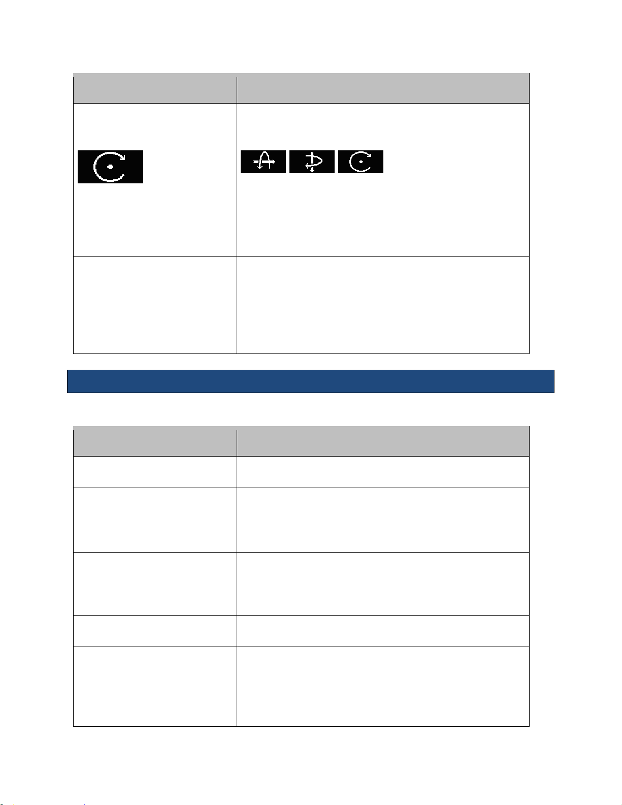
Rotation
(3 axes plus rotation)
Default Softkey:
Turn to rotate the selected plane or volume
Press to switch the axes. Default is Volume with Z-axis
Softkey options:
X-axis Y-axis Z-axis
Can alternatively use these Major Mode buttons on the Control
Panel:
M = X-axis / D = Y-axis / C = Z-axis
Threshold / Opacity / Brightness
Softkey Label:
Threshold / Opacity / Brightness
Selectable control with rotary action to adjust control parameters
Turn softkey to increase or decrease the value of each parameter
Press softkey to switch parameters
Default is Brightness
Can also use the B-Mode button to adjust Brightness
Control
Description/Use
Reset
Select to return volume back to original state
Mode
Press arrows to select an option:
Surface / Max Int / X-Ray / Min Int
Chosen option displays on Data Display
Render Quality
Changes the resolution quality of the rendered image
Press arrows to make selection: FAST / BALANCED / HIGH / MAX
Chosen option displays on Data Display
Tint
Press arrows to select among 4 tints:1 gray / 3 colorized
Render Smoothing
Press arrows to select the amount of smoothing desired:
0 / 1 / 2 / 3 / 4 / 5
Default is 3
Chosen option displays on Data Display
Menu Items
The Menu hard key displays the following options while in 3D/4D imaging:
z.one
Instructions for Use, Q00350-00, Rev D 47 | P a g e
pro
Page 48

Instructions for Use
Control
Description/Use
Invert
Toggles On / Off
Inverts volume image to black on white
Post-processing modes
The ZS3 supports three post-processing modes: Render, MPR, and Tomo
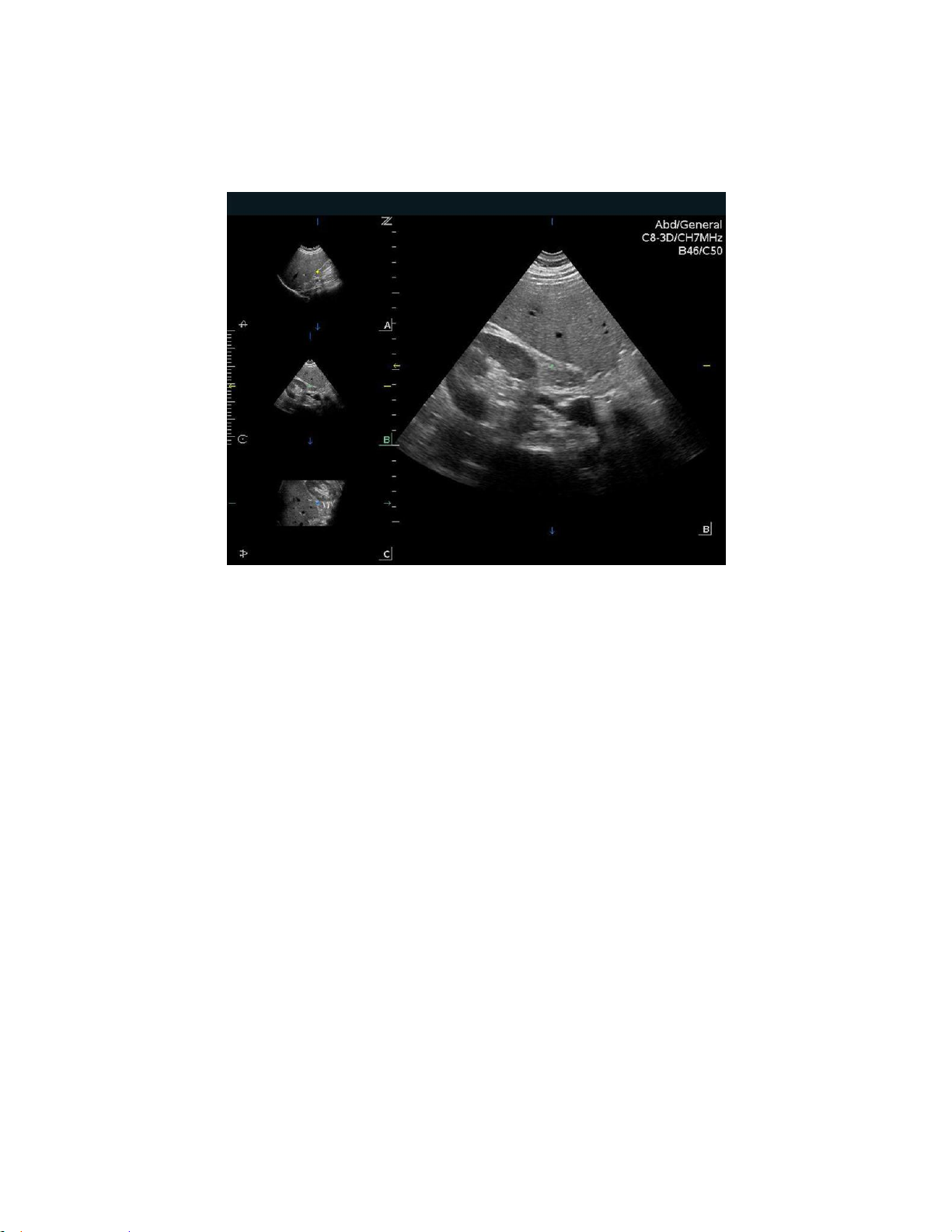
Render Mode
The imaging screen displays the surface volume image in a large format with the three
orthogonal image planes in a small format. The volume image (V) is the active window by
default.
z.one
Instructions for Use, Q00350-00, Rev D 48 | P a g e
pro
Figure 8-1: Render Mode
Page 49
Instructions for Use
MPR Mode
MPR mode displays orthogonal planes (A, B & C) vertically; larger image is blow up of active
image
Figure 8-2: MPR Mode
Features include:
• Ability to cycle (forward & backwards) through different windows - A, B, & C planes
• Ability to measure off primary image using system Measurement and OB Calcs options
• Thick Slice* feature under Menu/Tab secondary controls
*Thick Slice Mode: Integrates information along the z-axis to provide better contrast resolution. Maximum
intensity and minimum intensity modes are supported.
z.one
Instructions for Use, Q00350-00, Rev D 49 | P a g e
pro
Page 50

Instructions for Use
Tomo Mode
In Tomo mode, 9 images are displayed (9-up) with one image as reference for slices.
Figure 8-3: Tomo Mode
Features include the following abilities:
• Change line spacing between slices in mm and position of the set of lines using the Trackball
• Select reference image (one only) using softkey
• Toggle between One-up and 9-up
• Perform measurements on One-up image
• Toggle slice lines' orientation from vertical to horizontal via softkey
z.one
Instructions for Use, Q00350-00, Rev D 50 | P a g e
pro
Page 51

Instructions for Use
9. Maintenance
User Diagnostic Panel
The user diagnostic panel is accessed through the Service key on the back row of the keyboard.
A short press of that key activates the diagnostic panel. A long press of the key stores current
logs; the system beeps as logs are stored.
The user diagnostic panel supports the following:
Checking system software revision level
Checking system serial number
Checking revision levels of major PC boards
Capturing system status to log files
Capturing current image screen and storing as a BMP file
Transferring the contents of the internal log directory (using an internet connection) to the
ZONARE FTP site
Checking (over the Internet) for availability of software and firmware (cart) updates from the
ZONARE FTP site
System Care and cleaning
Before cleaning, turn off the AC circuit breaker on the z.one
the unit.
To clean the LCD display:
Clean the glass using a soft cotton cloth lightly moistened with a watery solution or a mild
commercial glass-cleaning product suited for coated glass surfaces.
Wipe dry with a clean, dry, soft, lint-free cloth.
Take care not to damage or scratch the glass or LCD panel. Do not apply pressure on the glass or
LCD panel. Do not apply or spray liquid directly to the glass, panel, or cabinet as excess liquid can
cause damage to internal electronics. Apply the liquid to the cleaning cloth.
To clean the External Case:
Do not use disinfectants (such as gluteraldahyde) or acetone to clean any surfaces on the z.one
system or its accessories.
Wipe the z.one
isopropyl alcohol and follow the disinfectant label instructions for use.
Do not spill or spray liquid directly on the control panel, LCD display or transducer connector.
surfaces with a safe disinfectant solution such as Sani-Cloth Plus or 50%
pro
system to remove all power from
pro
pro
z.one
Instructions for Use, Q00350-00, Rev D 51 | P a g e
pro
Page 52

Instructions for Use
Using soap and water or a mild disinfectant, gently wipe the surfaces of the z.one
system with a
pro
moistened cloth.
After each use, remove and dispose of any used cover/sheath. Wipe off any excess gel from the
transducer and clean it properly.
Air dry the z.one
system.
pro
z.one
Instructions for Use, Q00350-00, Rev D 52 | P a g e
pro
Page 53

Instructions for Use
10. Safety
It is not possible for ZONARE to anticipate every condition and situation in which ZONARE
ultrasound system will be used. The following warnings and cautions represent typical situations
that require special attention. User knowledge and experience with a specific application and
environment must also be taken into consideration in order to help ensure the safety of
personnel and equipment.
Safety Standards
All ZONARE instruments, cables, and diagnostic ultrasound imaging transducers have been
designed to meet the essential requirements contained in 93/42/EEC (Medical Device Directive),
and all appropriate requirements contained within UL 60601 (Standard Medical Electrical
Equipment, Part 1: General Requirements for Safety), IEC 60601 (Medical electrical equipment Part 1: General requirements for basic safety and essential performance), IEC 60601-2-37
(Medical electrical equipment - Part 2-37: Particular requirements for the safety of ultrasonic
medical diagnostic and monitoring equipment) and JIS-T-1501 (General Methods of Measuring
the Performance of Ultrasonic Pulse-Echo Diagnostic Equipment), including limits for current
leakage and isolation from a primary power line. Testing for compliance with the essential
requirements of the Medical Device Directive has been performed.
The following is a comprehensive list of the Warnings & Precautions associated with the use of
ZONARE’s ZS3 Ultrasound Platform and products derived there from (for example, but not
limited to, the ZS3 and the z.one
transducers.
with and without the SP UI option) and compatible
pro
Warnings
Do not remove any of the System covers other than the module cover. Other than the scan
module there are no user-serviceable parts internal to the system. Only trained ZONARE service
personnel should access the system’s internal electronics.
The ultrasound systems contain no operator-serviceable components within the enclosures. To
avoid electrical shock, do not remove covers. As with any other electrical equipment, always
observe care when operating this instrument. For service issues, contact ZONARE Technical
Support. Failure to follow these restrictions may void your warranty or service contract coverage.
To reduce the risk of electric shock, DO NOT connect the z.one
connections to equipment that is not properly connected to an Earth ground
z.one
Instructions for Use, Q00350-00, Rev D 53 | P a g e
pro
system input or output
pro
Page 54

Instructions for Use
To achieve proper grounding reliability, the ultrasound system power plug must be fully inserted
into a receptacle marked “hospital grade.” Do not remove the grounding wire. If there is any
question of power outlet or power cord integrity, do not proceed. Obtain qualified assistance
To maintain proper grounding reliability, use only ZONARE-recommended peripherals and
accessories. Use of non-specified peripherals and accessories could result in risk of electrical
shock or injury
The ultrasound systems represent a potential explosion hazard if used in the presence of
flammable anesthetics.
The system does not contain a user-serviceable lithium ion battery.
The optional ZPAK cart battery is not a user serviceable item. Contact ZONARE’s Technical
Support group for assistance with the ZPAK battery.
Follow guidelines provided by IEC 60601 when connecting peripherals.
The USB Memory Sticks supplied by ZONARE are the recommended brand, type, and sizes for use
in z.one
systems. They have been verified for optimum reliability and performance
pro
No modification of the system is permitted. Modifying the system may subject the operator or
patient to hazardous conditions.
To reduce the risk of electric shock, do not connect the z.one
input or output connections to
pro
equipment that is not properly connected to an Earth ground.
The z.one
ultrasound system represents a potential explosion hazard if used in the presence of
pro
flammable gases or oxygen rich environment.
Use only transducers that are specifically approved and licensed for the ultrasound system. If the
proper identification of a connected transducer is not displayed on screen, do not proceed with
its use.
Transducers covers may be contaminated and must be handled accordingly.
Inspect the transducer and z.one
Ultrasound System before each use. Inspect the transducer
pro
face, housing, cable, connectors, and cases. Do not use the unit if damage is detected.
Bent, broken, or missing pins on the transducer connector may cause poor image quality,
including possible mirror image artifact. Be sure to check pins before connecting transducer to
the ZONARE ultrasound system. If pins are bent, broken, or missing, do not use the transducer
and call ZONARE Technical Support.
To avoid electrical shock, always unplug the ultrasound system AC power cord from wall outlet
before cleaning any part. Do not immerse the transducer past the specified cleaning/disinfection
level, as specified in Transducer Cleaning and Disinfection (Q00066). Do not immerse the
transducer for longer than the specified cleaning/disinfecting time. Do not use any transducer
that has been immersed beyond the maximum limit or has been soaked longer than the
maximum specified time.
Do not allow disinfectant to contact metal surfaces. Always use protective eyewear and clothing
when cleaning or disinfecting device
Disinfectant wipes and topical spray products are not FDA cleared high-level disinfectants and do
not provide adequate protection should the transducer become cross-contaminated.
The transducer must be removed from patient contact before application of a high-voltage
defibrillation.
z.one
Instructions for Use, Q00350-00, Rev D 54 | P a g e
pro
Page 55

Instructions for Use
The system is not intended for use in conjunction with high frequency (HF) surgical equipment
(tissue ablation devices). Do not use transducers connected to the ultrasound system on patients
while HF surgical devices are in use.
If using IEC 60601 compliant equipment that was not provided by ZONARE, it is required that
total leakage currents be tested and validated to be below the IEC 60601 limits.
This equipment must only be connected to a supply main with protective earth.
Validate that measured and calculated results shown in Calc Package reports reflect the clinical
observations.
Auto-Dop Trace is intended to serve as an adjunct to the diagnostic process in evaluating blood
flow during PW Doppler examinations. When using the Auto-Dop Trace feature, please evaluate
the results to verify that you are in agreement before committing the values to the Calc Report
Package.
Always examine transducers for damage, such as cracks, splitting, holes, or fluid leaks. If damage
is evident, discontinue use of the transducer and contact ZONARE.
Prior to initiating any disinfection process, disconnect the transducer from the ultrasound system.
Ensure that any connected external equipment, such as external monitors, printers and
peripherals, comply with relevant standards such as IEC60601-1 and IEC60601-1-2.
If an external video monitor is connected to the z.one
RF ferrite is clamped to the cable as close to the z.one
system, it is necessary to ensure that an
pro
system as possible. Use a ferrite such as
pro
Fair-Rite Products Corp. 0431167281 (or an equivalent).
The potential equalization terminal, located by the AC Mains connection, is connected to the
system chassis. It can be connected to corresponding terminals on other equipment to eliminate
potential differences. Do NOT use it for additional protective grounding
Damage to the system may cause poor image quality, including possible imaging artifacts
sometimes referred to as ‘halo’ or ‘headlight’ artifacts. Regularly inspect the system for damage
and know how to recognize imaging artifacts.
There are many types of system use and system error messages that might be displayed during
the use of the z.one
Ultrasound System. If a message is encountered that is not self
pro
explanatory, contact ZONARE service for assistance.
Do not touch any of the connector contacts while performing a patient examination to prevent
the possibility of a hazardous current path.
Warnings - Ocular Imaging
To avoid injury to the patient, use only the Ocular Preset when imaging through the eye. The FDA
has established lower acoustic energy limits for ophthalmic use. The system will not exceed these
limits only if the Ocular Preset is selected
Warnings – Battery
To avoid electrical shock, do not touch the battery contact.
To avoid risk of fire, explosion, or burns:
Do not disassemble or alter the battery.
z.one
Instructions for Use, Q00350-00, Rev D 55 | P a g e
pro
Page 56

Instructions for Use
Do not short-circuit the battery by directly connecting the positive and negative terminals
with metal objects.
Do not heat or discard the battery in a fire.
Do not expose the battery to temperatures above 65° C (150° F).
Do not charge the battery near a heat source.
Do not leave the battery in direct sunlight.
Do not use a damaged battery.
Charge the battery at room temperature.
The battery should only be charged within the z.one
charger.
Inspect the battery for damage before charging or placing the battery in the z.one
System or a ZONARE provided battery
pro
pro
Do not connect battery to an electrical power outlet.
Do not continue to recharge the battery if it does not recharge fully after 4 hours.
To avoid electrical shock, do not touch the battery contact.
Warnings – ECG
The ECG and the Respirometer functionality are not intended for ECG diagnosis. It must not be
used for intraoperative applications of the heart. Use only the recommended patient cable
supplied by ZONARE. Make sure that bare parts of the electrodes and the patient do not come in
contact with conductive parts, such as metal examination beds, trolleys, and similar items.
Before defibrillation, always disconnect the ECG cable connector from the system and make sure
the connector does not come in contact with other persons or conductive surfaces, such as metal
examination beds, trolleys, and similar items.
Operating your system with ECG signals below 0.25 mV may cause inaccurate results.
Warnings – TEE Transducer
The multiplane TEE transducer should be used only by a qualified physician who has received
appropriate training in proper operation of the probe and in endoscopic techniques as dictated
by current relevant medical practices.
Electrical Hazard: Any evidence of damage indicates the probe cannot be used and should be
returned to ZONARE for evaluation and repair.
Biological Hazard: Adequate cleaning and, if necessary, disinfection are carried out to prevent
disease transmission. It is the responsibility of the user to verify and maintain the effectiveness of
the procedure used. A single-use, sterile disposable sheath for TEE purposes can be used.
Inspect the transducer connector pins for contamination or damaged pins that might interrupt
signal flow through the connection. Be sure to check pins before connecting transducer to the
ZONARE ultrasound system. If pins are bent, broken, or missing, do not use the transducer and
call ZONARE Technical Support.
Immediately replace a transducer that exhibits any damage symptoms.
Before introducing the probe, do not rub or spray the tip of the probe with an anesthetic agent.
System.
z.one
Instructions for Use, Q00350-00, Rev D 56 | P a g e
pro
Page 57

Instructions for Use
Avoid forceful manipulations and excessive force in using the probe that could result in patient
injury.
Withdraw the probe only with the deflection control in the unlock mode and with the distal end
of the probe straight.
The use of a bite guard is mandatory. Failure to use the bite guard may result in damage to the
probe, which could result in a safety hazard. Damage to the probe due to biting is not covered by
the probe's warranty.
Check if the maximum deflection of the tip is 90° to 120° upward, 60° to 90° downwards and 30°
to 45° left/right. If the deflection shows an unwanted amount of free play or exceeds the maximal
deflection angles given above, do not use the probe. Contact the service organization to re-adjust
the steering of the probe. In this way, the risk of "buckling" or "U-turning" of the probe in the
esophagus is minimized.
Avoid damage to the probe by allowing nothing to protrude beyond the case when closing the
lid.
Prior to cleaning any device, turn off the system and disconnect power cord from AC power
source to avoid electrical shock.
Always use protective eyewear and clothing when cleaning or disinfecting the transducers.
Do not allow the disinfectant to come in contact with metal surfaces (transducer connector). Use a
soft cloth and warm soapy water to remove any disinfectant that remains on metal surfaces.
Keep the control handle and transducer connector out of any cleaning or disinfection solutions.
The control handle and cable may be cleaned with a damp cloth, but only the distal end of the
probe up to the 100cm marker on the shaft may be placed into a disinfection solution.
Do not use other disinfection methods like Iodine, Steam, Heat or Ethylene Oxide.
When servicing the z.one
System, always be sure to turn the circuit breaker to the OFF position.
pro
Precautions
Transducers are individually licensed according to system configuration. Only the
following transducers are available without an advanced feature configuration: C4-1, C62, C9-3, C9-3sp, C8-3 3D, C10-3, E9-3 3D, E9-3, E9-4, L8-3, L10-5, L14-5w, L14-5sp, L20-5,
P4-1c and P8-3TEE. The A2CW and A5CW transducers are enabled if the system is
configured with either the Echocardiography or the Advanced Vascular Imaging Feature
Sets. Attempting to use any other transducers will result in an error message.
Be aware of the potential hazards associated with the environment where the ultrasound
systems will be used. The systems and/or the external equipment can be damaged if
signal levels are not appropriate. If peripheral equipment not specifically authorized by
ZONARE is to be connected to the system, it must meet all applicable electrical safety
standards that apply to the system in order to maintain ZONARE’s safety integrity. Any
equipment not supplied by ZONARE must be approved by ZONARE. Use of nonZONARE-approved equipment may result in an unsafe condition, impair operation of the
z.one
Instructions for Use, Q00350-00, Rev D 57 | P a g e
pro
Page 58

Instructions for Use
ultrasound system, impair diagnostic capabilities, and void your warranty or service
contract coverage.
ZONARE transducers have a specific range of acceptable application use. Users are
advised to restrict each transducer’s use to those applications. Excessive bending,
twisting, pulling, dragging, or compression of transducer cables may cause failure or
intermittent operation of the system. Avoid rolling the cart wheels over cables. Use of
cable hooks is recommended to minimize chance of damage to cables.
If a transducer that has not been approved and licensed for use with the ultrasound
system to which it is connected, or if a licensed transducer is not properly connected, the
corresponding transducer identification data will not display on the LCD Display. Imaging
will be disabled. Resolve this issue before continuing use.
The ultrasound system and/or the transducer could be damaged if a nonapproved
transducer is connected.
Improper cleaning or disinfection of patient applied parts may cause permanent
damage. Carefully review the manufacturer’s directions for any component used with
ZONARE ultrasound systems. ZONARE Medical Systems, Inc. assumes no liability with
respect to single-use devices that are reused, reprocessed, or resterilized and makes no
warranties, expressed or implied (including the warranties of merchantability or fitness
for a particular use), with respect to such devices.
Use of peripherals or other equipment not provided by ZONARE may result in system
damage or degraded performance. Carefully review the labeling of any such equipment
before connecting to the ZONARE system.
Improper setting of imaging controls may obscure diagnostically valuable information in
the display. The factory default preset maps were preselected as appropriate for most
imaging circumstances. Improper user configuration of custom presets may obscure
diagnostically valuable information.
ZONARE ultrasound systems are manufactured in compliance with existing
electromagnetic immunity (EMI) and electromagnetic compatibility (EMC) requirements.
Use of the systems in the presence of an electromagnetic field can cause degradation of
the ultrasound image.
Electrostatic discharge (ESD), or static shock, is a naturally occurring phenomenon. ESD is
common in low humidity, which can be caused by heating or air conditioning. ESD shock
occurs when electrical energy is discharged from one body, to a differently charged
body. To lessen the occurrence of ESD, use antistatic spray on carpets and flooring, and
antistatic mats.
To minimize potential ESD damage and electrical contact contamination, avoid touching
the metal contacts for the transducer connections, at both the Ultrasound System port
(z.one
) and the transducer connector.
pro
z.one
Instructions for Use, Q00350-00, Rev D 58 | P a g e
pro
Page 59

Instructions for Use
If the z.one
temperature and/or humidity, allow the z.one
System has been moved between environments with extremes of
pro
System to rest for at least 30 minutes in
pro
a controlled environment before using.
Do not use the ultrasound system if any error message displays on the screen.
Do not block airflow to any ventilation holes on the system.
Do not submerge the transducer past the points indicated in ‘ZONARE Transducers
Cleaning and Disinfection’ (Q00066).
Do not spill liquid on the systems or transducers.
Using a non-recommended cleaning or disinfectant solution, incorrect solution strength,
or immersing the transducer deeper or longer than indicated can damage the
transducer. Damages linked to the use of disapproved chemicals are not covered under
product warranty or service contract.
The use of non-shielded cables may result in increased emissions and decreased
immunity to external signals
Operating the systems in the presence of external electromagnetic fields can degrade
the quality of the ultrasound image. High-frequency devices, such as electro-surgical
devices, can produce image artifacts. If required, a review of the local electromagnetic
environment may be required to minimize the sources of external noise generators.
The use of non-ZONARE approved cables and accessories may result in increased
radiated emissions as well as decreased immunity to external signal fields.
Before beginning to image a new patient, be sure to conclude any in-progress patient
exam by pressing the New Patient key. Failure to do so will result in any subsequent
storing of images being mistakenly written to the previous patient exam directory.
Some components or devices such as transducer covers used with ZONARE systems are
for single-patient use only. Reuse, reprocessing, or re-sterilization of these devices may
compromise their structural integrity.
Any image sets stored on the system, which are not identified by patient name and
number, will be stored with a unique number based off of the system ID.
Exercise care in adjusting all settings to avoid obscuring low-level signals that may have
diagnostic value. Improper settings can seriously degrade image quality.
Do not touch exposed metal of transducer connector.
Validate all entries in the Measurement Summary.
Ultrasound imaging capabilities can vary from patient to patient. Ultrasound should be
used as one component in a comprehensive diagnostic plan.
Never leave a probe in the disinfection solution for more than 45 minutes. Please refer to
the instructions for use that came with the disinfectant for minimal required exposure
times. Do not forget to rinse the probe directly after disinfection.
z.one
Instructions for Use, Q00350-00, Rev D 59 | P a g e
pro
Page 60

Instructions for Use
Only use water-soluble acoustic coupling gel. Other coupling gels can cause probe
damage.
Long-term exposure to ultrasound should be minimized. Although there have been no
confirmed adverse effects produced by diagnostic levels of ultrasound, unnecessary
patient exposure to ultrasound energy should be avoided, especially in the Doppler
mode.
Use of a non-compatible USB Memory Stick may result in file corruption or long file
transfer times. Please confirm proper operation of any memory stick prior to attempting
to use for clinical data.
Make sure the z.one
System has fully completed downloading upgrades,
pro
importing/exporting, or collecting log data to the USB Memory Stick before removing it
from the z.one
System. Failure to do so will result in loss of data.
pro
Wide variability in CD and DVD quality may prevent the system from reliably writing to
and reading from some commercially available discs. ZONARE has tested the CD and
DVD. For up-to-date CD/DVD recommendations, go to:
http://www.zonare.com/support/accessories/media.
Before deleting any Exam data from the z.one
System, always verify that data was
pro
successfully transferred to the CD/DVD by viewing it on an external reader/player..Review
the user maintenance section of the instructions for use for proper technique and
approved agents for cleaning the external surfaces of the system.
Review the z.one
DICOM conformance statement before integrating with any PACS
pro
system.
Validate Structured Report export prior to clinical use.
Use-time from the optional z.one
battery pack will vary depending on the system
pro
usage and battery conditioning. Ensure the battery is adequately charged before
starting a procedure without AC main power.
Export patient studies in a timely manner. Do not use the system storage as the sole
location of patient studies for an extended period of time.
IQ scan data should not be relied on for primary storage of diagnostic data. Use of IQ
scan data across software versions is not guaranteed.
Diagnostic data exported to CD/DVD should be verified on an external system before
deleting that data from the z.one
The system is not indicated for differentiation between malignant and benign breast
system.
pro
lesions.
z.one
Instructions for Use, Q00350-00, Rev D 60 | P a g e
pro
Page 61

Instructions for Use
Precautions – TEE Transducer
TEE: Perform an electrical leakage test prior to each use of the transducer. See the TEE
Maintenance Guide (Q00195) or the TEE Leakage Test Quick Reference Guide (Q00192)
for details.
TEE: Examine the transducer prior to each use. See the TEE Maintenance Guide
(Q00195) or the TEE Quick Reference Guide (K90056) for details.
TEE: Clean and disinfect after each use.
TEE: Always use a bite guard.
TEE: Always use single-use probe sheath.
TEE: Ensure articulation locks are disengaged and straighten mechanism during device
insertion or extraction from patient.
TEE: Remove the transducer from the patient prior to defibrillation.
TEE: Handle with care, very delicate instrument.
TEE: Do not store the disinfected transducer in the carrying case. Only use the case for
transportation.
TEE transducer is a delicate medical instrument, handle with care.
The multiplane TEE probe is a precision instrument, which must be handled with care. It
may be damaged when dropped or abused. In particular, do not allow the ultrasonic
window in the tip to come into contact with a sharp object. Do not touch this window
unnecessarily. Never exert force onto the acoustic window.
The transducer connector is not watertight, and should always be kept dry. The control
handle, although spray-watertight, should not be immersed.
This equipment contains no operator serviceable components. To prevent electric shock,
do not remove any covers or panels.
Never manually deflect the distal tip of the probe; use only the deflection control
wheels.
Do not kink, tightly coil, or apply excessive force on the probe cable or shaft. Insulation
failure may result.
Under normal conditions at full acoustic power the temperature of the tip does not
exceed 43°C. Be sure to check at least monthly that the temperature increase of the tip is
within limits:
Connect the probe to the Ultrasound system.
Adjust the acoustic power to the highest value possible.
Select Color Doppler mode.
Wait for 2 minutes.
Feel at the distal end of the probe if there is a temperature increase that could be
harmful for the patient.
z.one
Instructions for Use, Q00350-00, Rev D 61 | P a g e
pro
Page 62

Instructions for Use
When a brush is used for cleaning the transducer, use only a soft brush; coarse/stiff-bristle
brushes may cause transducer damage
Keep the control handle and transducer connector out of any cleaning or disinfection solutions.
The control handle and cable may be cleaned with a damp cloth, but only the distal end of the
probe up to the 100cm marker on the shaft may be placed into a disinfection solution.
During immersion disinfection, never immerse the transducers longer than 45 minutes. Damage
may occur to the transducer housing and/or components if disinfection times exceed these
recommended limits.
Precautions – 3D/4D Imaging
3D: Measurements out of plane are potentially less accurate due to movement of tissue.
A good B Mode/2D image is important for a high-quality 3D/4D image.
Precautions - WIRELESS
WIRELESS: The ZONARE Wireless option device is an RF Receiver and Transmitter, operating using
industry standard 802.11 b/g protocols. Use of the wireless option, in the presence of other high
energy RF radiating devices may interfere with the transmission of data to the network interfaces.
WIRELESS: The ZONARE Wireless option device supports several industry standard security
protocols and should be enabled to reduce the chance of patient data, transmitter over the
wireless interface from the possible undesired interception of the data.
WIRELESS: Data transmission and reception rates are limited to by the bandwidth of the user’s
network infrastructure. A Quality of Service (QOS) level is determined by the number of users on
the network, the data being transferred by the users, distance of the ZONARE system to the
wireless access point and other factors.
z.one
Instructions for Use, Q00350-00, Rev D 62 | P a g e
pro
Page 63

Instructions for Use
Electrical Safety
ZONARE systems meet IEC 60601, Class I powered equipment requirements.
The z.one
published in the European Norm (EN) and International Electronics Consortium (IEC) Harmonized
Standards.
The transducers, when used with the z.one
60601 as Type BF or Type CF applied patient parts. Each transducer or port is labeled accordingly.
ultrasound system complies with the applicable medical equipment requirements
pro
system, are certified to be in compliance with IEC
pro
Contrast Imaging
Cardiac rhythm disturbances during perfusion studies using gas ultrasound contrast agents have
been observed in the diagnostic range of MI values. See the Instructions for Use that came with
contrast agent being used for details.
Medical Ultrasound Safety - General
Anyone using ZONARE ultrasound systems for human exams of any kind should thoroughly
understand the implications of such use. The American Institute of Ultrasound in Medicine
(AIUM) has published a document titled Medical Ultrasound Safety (AIUM 1994). ALARA is an
abbreviation for the principle of prudent use of diagnostic ultrasound by obtaining the
diagnostic information at a power output that is as low as reasonably achievable.
Diagnostic ultrasound is a technique-dependent imaging modality. To obtain the best possible
patient care from any ultrasound equipment, the system must be operated by personnel trained
in ultrasound image acquisition and interpretation. Users must become familiar with each of
their imaging systems.
Always make sure appropriate transducer is used for study being performed
Always make sure active preset is appropriate for study being performed
Know how to recognize acoustic artifacts in image
Consult AIUM recommended protocols & equipment specifications.
z.one
Instructions for Use, Q00350-00, Rev D 63 | P a g e
pro
Page 64

Instructions for Use
11. Acoustic Output
This section describes acoustic-output-related parameters and considers the relation between
these parameters and user controls on the ZONARE systems. The display accuracy and
measurements precision of these parameters is also discussed.
Detailed information on acoustical power output for each transducer, in each operating
modality, is in the dedicated tables provided in section 12.
Acoustical power output is dependent on both system control settings and the probe selected.
ALARA Principle
The prudent use of ultrasound requires a constant consideration of the risk-benefit ratio for the
patient, along with employment of the ALARA principle. ALARA stands for as low as reasonably
achievable. ALARA means that the sonographer uses only a much ultrasonic power for as long
as needed to obtain the necessary clinical information. With training, education, and experience,
the sonographer can systematically keep the patient risk for potential bioeffects of ultrasound to
a minimum. ALARA is the guiding principle for the use of diagnostic ultrasound. Qualified
sonographers, using good judgment and insight, determine the exposure that is as low as
reasonably achievable. There are no rules to determine the correct response to every situation.
The sonographer keeps exposure low, bioeffects minimal, and images diagnostic. A thorough
knowledge of the imaging modes, probes, system, and scanning techniques for this system is
necessary.
The acoustic output of the ZONARE ultrasound systems has been measured and calculated per the
Acoustic Output Measurement Standard for Acoustic Output Measurement Standard for
Diagnostic Ultrasound Equipment, Revision 3 (NEMA, UD 2) and the Standard for Real-Time
Display of Thermal and Mechanical Acoustic Output Indices on Diagnostic Ultrasound
Equipment, Revision 2 (NEMA UD3).
Applying ALARA
The scanner-imaging mode is selected by the sonographer and is determined by what
information is required, For example, 2D imaging provides anatomical information.
z.one
Instructions for Use, Q00350-00, Rev D 64 | P a g e
pro
Page 65

Instructions for Use
Understanding the nature of the imaging mode being used allows a trained sonographer to
apply the ALARA principle.
With training, education, and experience, the sonographer can systematically keep the patient
risks for potential bioeffects of ultrasound down to a minimum. This means using ultrasound as
an effective and often essential source of diagnostic information and not as a source of
entertainment.
For information about ALARA and possible bioeffects, refer to the Medical Ultrasound Safety
brochure developed by the American Institute of Ultrasound in Medicine (AIUM) and supplied
with ZONARE ultrasound systems.
Direct Controls
Per 60601-2-37, the ultrasound system control acoustic output to not exceed a mechanical
index (MI) level of 1.9, an I
The systems’ factory-set defaults, which are user adjustable, are such that when changing from
one preset to another, one transducer to another, or a non-fetal to a fetal application, the
system selects default MI & I
Electrical Equipment Part 2-37: Particular Requirements for the Safety of Ultrasonic Medical
Diagnostic and Monitoring Equipment and the United States Food and Drug Administration’s
Guidance Document, “Information for Manufacturers Seeking Marketing Clearance of Diagnostic
Ultrasound Systems and Transducers” limits.
The thermal index that is displayed (TIS, TIB, TIC) is based on the selected application.
The system acoustic output display and controls follow the "Standard for Real-Time Display of
Thermal and Mechanical Acoustic Output Indices on Diagnostic Ultrasound Equipment, Revision 2"
(NEMA UD3).
of 720 mW/cm2 or a thermal index (TI) value of 6.0.
SPTA.3
values that are significantly lower than 60601-2-37, Medical
SPTA.3
Indirect Controls
The controls that indirectly affect output are controls affecting the imaging mode, optimization,
probe selection, and depth. The imaging mode determines the nature of the ultrasound beam.
Tissue attenuation is directly related to transducer frequency. The higher the pulse repetition
frequency (PRF), the more output pulses occur over a period of time.
z.one
Instructions for Use, Q00350-00, Rev D 65 | P a g e
pro
Page 66

Instructions for Use
Receiver Controls
The receiver controls (such as Gain, Dynamic Range, etc.) do not affect acoustic output. Use the
receiver controls to improve the image quality before using controls that directly or indirectly
affect output.
General Controls
Transducer: Each ZONARE transducer has different physical characteristic and acoustic response
to transmit voltages. Differences include size and shape, center frequency, piezo-electric
efficiency, and focus properties of the lens. Changing from one transducer model to another will
change the acoustic output and therefore the displayed mechanical index and thermal index
values.
Mode: Changing from one mode to another will affect the acoustic output. Different modes use
different transmit waveforms, focusing, duty cycles, and pulsing sequences. Doppler modes tend
to have higher duty cycles, and therefore higher TI values, than B and M modes. Modes using
the tightest focusing will tend to have higher MI values.
Defaults: Default settings exist and are accessed whenever a transducer and mode combination
is selected. Although the acoustic output associated with these defaults may differ from
combination to combination, the default acoustic output is lower than 60601-2-37, Medical
Electrical Equipment Part 2-37: Particular Requirements for the Safety of Ultrasonic Medical
Diagnostic and Monitoring Equipment and the United States Food and Drug Administration’s
Guidance Document, “Information for Manufacturers Seeking Marketing Clearance of Diagnostic
Ultrasound Systems and Transducers” limits..
Transmit Power: Transmit power controls the transmit voltage, and therefore the amplitude of
the transmitted ultrasonic waves. Both the TI and the MI will change when Transmit power (A
Output) is adjusted.
Automatic ZONARE Limiting: For any adjustment described in the mode-specific section
below, when a user adjustment of an ultrasound system control causes the MI, TI, or any other
acoustic output or surface-temperature related parameter to reach a system control limit, the
ZONARE system will automatically decrease the transmit voltage, causing a decrease in one or
more of those parameters.
z.one
Instructions for Use, Q00350-00, Rev D 66 | P a g e
pro
Page 67

Instructions for Use
B-Mode Controls
Image Width: Narrowing the image width may increase the frame rate, which may increase
the TI.
Depth: Decreasing the depth may increase the frame rate, which may increase the TI.
Operating Frequency: Changing the operating frequency will affect the displayed MI and TI
values as the beam formation is affected and transducer efficiencies may differ between
frequencies.
Frame Rate: A lower frame rate may decrease the TI; however, due to an increase in the Image
Width, the TI stays roughly constant if the system’s transmit pulse repetition stays constant.
Zoom: Increasing or decreasing the zoom may affect the frame rate, which may increase or
decrease the TI.
Image Presets: Changing the image presets may indirectly change the acoustic line spacing or
the frame rate, which could change the TI values. An increasing spacing may decrease the TI,
and an increasing frame rate may increase the TI.
M-Mode Controls
Depth: Decreasing the depth may increase the frame rate, which may increase the TI.
Operating Frequency: Changing the operating frequency will affect the displayed MI and TI
values as the beam formation is affected and transducer efficiencies may differ between
frequencies.
Image Presets: Changing the image presets may indirectly change the acoustic line spacing or
the frame rate, which could change the TI values. An increasing spacing may decrease the TI,
and an increasing frame rate may increase the TI.
z.one
Instructions for Use, Q00350-00, Rev D 67 | P a g e
pro
Page 68

Instructions for Use
Color Doppler Controls
Image Width: Narrowing the image width may increase the frame rate, which may increase the
TI.
Velocity Scale: Increasing the Velocity scale may increase the TI by increasing the pulse
repetition frequency.
Color ROI Size and Position: A narrower Color Region Of Interest (ROI) may increase the frame
rate, which may increase the TI. A longer Color ROI, or a deeper Color ROI, may decrease the
pulse repetition frequency and decrease the TI.
Operating Frequency: Changing the operating frequency will affect both the displayed MI and
TI values because the beam formation is affected and transducer efficiencies may differ between
frequencies.
Combinational with B-Mode: Use of combination modes affects the TI and the MI through the
combination of pulse types. Because the TI is additive, simultaneous pulsing of B and COLOR
modes will cause larger TI values than sequential pulsing (e.g. auto-update). The displayed MI
will be from the pulses with the largest peak pressure.
Image Presets: Changing the image presets may indirectly change the color sensitivity.
Increasing the sensitivity could increase the TI values.
Color Doppler Triplex Controls
Image Width: Narrowing the image width may increase the frame rate, which may increase the
TI.
Velocity Scale: Increasing the Velocity scale may increase the TI by increasing the pulse
repetition frequency.
Color ROI Size and Position: A narrower Color Region of Interest (ROI) may increase the frame
rate, which may increase the TI. A longer Color ROI, or a deeper Color ROI, may decrease the
pulse repetition frequency and decrease TI.
z.one
Instructions for Use, Q00350-00, Rev D 68 | P a g e
pro
Page 69

Instructions for Use
PW Gate Size: A smaller PW Gate size may increase the allowable pulse repetition frequency
and may increase TI.
PW Gate Position: A shallower PW Gate position may increase the allowable pulse repetition
frequency and may increase the TI.
Operating Frequency: Changing the operating frequency will affect both the displayed MI and
TI values because the beam formation is affected and transducer efficiencies may differ between
frequencies.
Combinational with B, COLOR and PW: Use of combination modes affects the TI and MI
through the combination of pulse types. Because the TI is additive, simultaneous pulsing of B,
COLOR and PW modes may cause larger TI values than sequential pulsing (e.g. auto-update).
The displayed MI will be from the pulses with the largest peak pressure.
Image Presets: Changing the image presets may indirectly change the PW and/or color
sensitivity. Increasing the sensitivity could increase the TI values.
PW Doppler Controls
Velocity Scale: Increasing the Velocity scale may increase the TI by increasing the pulse
repetition frequency.
PW Gate Size: A smaller PW Gate size may increase the allowable pulse repetition frequency
which may increase TI.
PW Gate Position: A shallower PW Gate position may increase the allowable pulse repetition
frequency and may increase TI.
Operating Frequency: Changing the operating frequency will affect both the displayed MI and
TI values because the beam formation is affected and transducer efficiencies may differ between
frequencies.
Combinational with B-Mode: Use of combination modes affects the TI and MI through the
combination of pulse types. Because the TI is additive, simultaneous pulsing of B and PW
modes may cause larger TI values than sequential pulsing (e.g. auto-update). The displayed MI
will be from the pulses with the largest peak pressure.
z.one
Instructions for Use, Q00350-00, Rev D 69 | P a g e
pro
Page 70

Instructions for Use
Image Presets: Changing the image presets may indirectly change the PW sensitivity.
Increasing the sensitivity could increase the TI values.
CW Doppler Controls
CW Gate Position: Changes in the CW Gate position may change the MI or TI.
Operating Frequency: Changing the operating frequency will affect both the displayed MI and
TI values because the beam formation is affected and transducer efficiencies may differ between
frequencies.
Image Presets: Changing the image presets may indirectly change the CW sensitivity. Increasing
the sensitivity could change the TI values.
z.one
Instructions for Use, Q00350-00, Rev D 70 | P a g e
pro
Page 71

Instructions for Use
Measured Item
Measured Result
Penetration Depth
N/A
Resolution (Axial)
N/A
Resolution (Lateral)
N/A
Ultrasound Frequency
2.0 MHz
Ultrasound Bandwidth
N/A
Highest Observed Surface Temp
37.5° C
Doppler Velocity Range in PW
N/A
Doppler Velocity Range in CW
+/- 1800 cm/s
Measured Item
Measured Result
Penetration Depth
N/A
Resolution (Axial)
N/A
Resolution (Lateral)
N/A
Ultrasound Frequency
5.0 MHz
Ultrasound Bandwidth
N/A
Highest Observed Surface Temp
37.4° C
Doppler Velocity Range in PW
N/A
Doppler Velocity Range in CW
+/- 750 cm/s
12. Transducers Performance
The information in the following tables describes the measured performance characteristics of
each of the transducers currently supported on the z.one
A2CW Transducer: Measured Results
ultrasound system.
pro
A5CW Transducer: Measured Results
z.one
Instructions for Use, Q00350-00, Rev D 71 | P a g e
pro
Page 72

Measured Item
Measured Result
Penetration Depth
30 cm
Resolution (Axial)
0.6 mm
Resolution (Lateral)
1.6 mm
Ultrasound Frequency
2.24 MHz
Ultrasound Bandwidth
0.686 MHz
Highest Observed Surface Temp
39.7° C
Doppler Velocity Range in PW
+/- 375 cm/s
Doppler Velocity Range in CW
+/- 2500 cm/s
Measured Item
Measured Result
Penetration Depth
24 cm
Resolution (Axial)
0.4 mm
Resolution (Lateral)
0.9 mm
Ultrasound Frequency
3.96 MHz
Ultrasound Bandwidth
1.42 MHz
Highest Observed Surface Temp
40.2° C
Doppler Velocity Range in PW
+/- 450 cm/s
Doppler Velocity Range in CW
N/A
C4-1 Transducer: Measured Results
C6-2 Transducer: Measured Results
Instructions for Use
z.one
Instructions for Use, Q00350-00, Rev D 72 | P a g e
pro
Page 73

Measured Item
Measured Result
Penetration Depth
24 cm
Resolution (Axial)
0.3 mm
Resolution (Lateral)
0.8 mm
Ultrasound Frequency
4.8 MHz
Ultrasound Bandwidth
3.6 MHz
Highest Observed Surface Temp
41.0° C
Doppler Velocity Range in PW
+/- 350 cm/s
Doppler Velocity Range in CW
N/A
Measured Item
Measured Result
Penetration Depth
18 cm
Resolution (Axial)
0.3 mm
Resolution (Lateral)
0.7 mm
Ultrasound Frequency
5.85 MHz
Ultrasound Bandwidth
2.31 MHz
Highest Observed Surface Temp
40.7° C
Doppler Velocity Range in PW
+/- 350 cm/s
Doppler Velocity Range in CW
N/A
C8-3 3D Transducer: Measured Results
C9-3 Transducer: Measured Results
Instructions for Use
z.one
Instructions for Use, Q00350-00, Rev D 73 | P a g e
pro
Page 74

Measured Item
Measured Result
Penetration Depth
18 cm
Resolution (Axial)
0.3 mm
Resolution (Lateral)
0.7 mm
Ultrasound Frequency
5.65 MHz
Ultrasound Bandwidth
3.17 MHz
Highest Observed Surface Temp
40.9° C (external) 41.8° C (internal)
Doppler Velocity Range in PW
+/- 350 cm/s
Doppler Velocity Range in CW
N/A
Measured Item
Measured Result
Penetration Depth
13 cm
Resolution (Axial)
0.2 mm
Resolution (Lateral)
0.8 mm
Ultrasound Frequency
7.47 MHz
Ultrasound Bandwidth
2.68 MHz
Highest Observed Surface Temp
39.7° C
Doppler Velocity Range in PW
+/- 250 cm/s
Doppler Velocity Range in CW
+/- 1000 cm/s
C9-3sp Transducer: Measured Results
C10-3 Transducer: Measured Results
Instructions for Use
z.one
Instructions for Use, Q00350-00, Rev D 74 | P a g e
pro
Page 75

E9-3 3D Transducer: Measured Results
Measured Item
Measured Result
Penetration Depth
12 cm
Resolution (Axial)
0.2mm
Resolution (Lateral)
0.9 mm
Ultrasound Frequency
6.49 MHz
Ultrasound Bandwidth
2.38 MHz
Highest Observed Surface Temp
40.7° C
Doppler Velocity Range in PW
+/- 250 cm/s
Doppler Velocity Range in CW
N/A
Instructions for Use
z.one
Instructions for Use, Q00350-00, Rev D 75 | P a g e
pro
Page 76

Measured Item
Measured Result
Penetration Depth
13 cm
Resolution (Axial)
0.2 mm
Resolution (Lateral)
0.7 mm
Ultrasound Frequency
7.81 MHz
Ultrasound Bandwidth
2.92 MHz
Highest Observed Surface Temp
39.3° C
Doppler Velocity Range in PW
+/- 200 cm/s
Doppler Velocity Range in CW
N/A
Measured Item
Measured Result
Penetration Depth
13 cm
Resolution (Axial)
0.3 mm
Resolution (Lateral)
0.8 mm
Ultrasound Frequency
6.775 MHz
Ultrasound Bandwidth
2.355 MHz
Highest Observed Surface Temp
41.0° C
Doppler Velocity Range in PW
+/- 200 cm/s
Doppler Velocity Range in CW
N/A
E9-3 Transducer: Measured Results
E9-4 Transducer: Measured Results
Instructions for Use
z.one
Instructions for Use, Q00350-00, Rev D 76 | P a g e
pro
Page 77

L8-3 Transducer: Measured Results
Measured Item
Measured Result
Penetration Depth
10 cm
Resolution (Axial)
0.2 mm
Resolution (Lateral)
0.5 mm
Ultrasound Frequency
6.33 MHz
Ultrasound Bandwidth
3.32 MHz
Highest Observed Surface Temp
40.6° C
Doppler Velocity Range in PW
+/- 700 cm/s
Doppler Velocity Range in CW
N/A
Measured Item
Measured Result
Penetration Depth
10 cm
Resolution (Axial)
0.2 mm
Resolution (Lateral)
0.4 mm
Ultrasound Frequency
6.48 MHz
Ultrasound Bandwidth
3.47 MHz
Highest Observed Surface Temp
39.8° C
Doppler Velocity Range in PW
+/- 325 cm/s
Doppler Velocity Range in CW
N/A
L10-5 Transducer: Measured Results
Instructions for Use
z.one
Instructions for Use, Q00350-00, Rev D 77 | P a g e
pro
Page 78

L20-5 Transducer: Measured Results
Measured Item
Measured Result
Penetration Depth
5 cm
Resolution (Axial)
0.1 mm
Resolution (Lateral)
0.1 mm
Ultrasound Frequency
13.2 MHz
Ultrasound Bandwidth
5.4 MHz
Highest Observed Surface Temp
40.5 ° C
Doppler Velocity Range in PW
+/- 225 cm/s
Doppler Velocity Range in CW
N/A
Measured Item
Measured Result
Penetration Depth
6 cm
Resolution (Axial)
0.2 mm
Resolution (Lateral)
0.3 mm
Ultrasound Frequency
10.2 MHz
Ultrasound Bandwidth
3.54 MHz
Highest Observed Surface Temp
39.0° C (external) 40.0° C (internal)
Doppler Velocity Range in PW
+/- 600 cm/s
Doppler Velocity Range in CW
N/A
L14-5sp Transducer: Measured Results
Instructions for Use
z.one
Instructions for Use, Q00350-00, Rev D 78 | P a g e
pro
Page 79

L14-5w Transducer: Measured Results
Measured Item
Measured Result
Penetration Depth
10 cm
Resolution (Axial)
0.1 mm
Resolution (Lateral)
0.3 mm
Ultrasound Frequency
8.0 MHz
Ultrasound Bandwidth
5.0 MHz
Highest Observed Surface Temp
39.5° C
Doppler Velocity Range in PW
+/- 300 cm/s
Doppler Velocity Range in CW
N/A
Measured Item
Measured Result
Penetration Depth
30 cm
Resolution (Axial)
0.4 mm
Resolution (Lateral)
2.4 mm
Ultrasound Frequency
3.19 MHz
Ultrasound Bandwidth
1.2 MHz
Highest Observed Surface Temp
40.9° C
Doppler Velocity Range in PW
+/- 450 cm/s
Doppler Velocity Range in CW
+/- 1450 cm/s
P4-1c Transducer: Measured Results
Instructions for Use
z.one
Instructions for Use, Q00350-00, Rev D 79 | P a g e
pro
Page 80

P8-3 TEE Transducer: Measured Results
Measured Item
Measured Result
Penetration Depth
1.3 cm
Resolution (Axial)
0.3 mm
Resolution (Lateral)
1.5 mm
Ultrasound Frequency
6.67 MHz
Ultrasound Bandwidth
2.60 MHz
Highest Observed Surface Temp
42.4° C
Doppler Velocity Range in PW
+/- 550 cm/s
Doppler Velocity Range in CW
+/- 960 cm/s
Measured Item
Measured Result
Penetration Depth
9.0 cm
Resolution (Axial)
0.3 mm
Resolution (Lateral)
0.8 mm
Ultrasound Frequency
6.49 MHz
Ultrasound Bandwidth
2.5 MHz
Highest Observed Surface Temp
40.5° C
Doppler Velocity Range in PW
+/- 180 cm/s
Doppler Velocity Range in CW
+/- 720 cm/s
P9-3icTransducer: Measured Results
Instructions for Use
z.one
Instructions for Use, Q00350-00, Rev D 80 | P a g e
pro
Page 81

Instructions for Use
13. Transducers: Acoustic Power Output
Acoustical power output varies among different models of probes. Specific acoustic power
output values for each transducer, for each mode of operation, are provided in tables below.
The defaults of each probe/mode combination will be set such that the acoustic output will be
less than either 3 dB below the maximum acoustic output for the operating condition or 6 dB
below FDA limits. 6 dB equates to 50% of the FDA limit for MI, and 25% of the limit for Ispta.3
and TI.
The tables on the following pages specify the Track 3 reporting values in each operating
modality for each ZONARE transducer.
Ophthalmic Use
Under Track 3, acoustic output will not be evaluated on an application-specific basis, but the
global maximum derated ISPTA should be = 720 mW/cm2, and either the global maximum MI
should be = 1.9 or the global maximum derated ISPPA should be = 190 W/cm2. An exception is
for ophthalmic use, in which case, the acoustic output is limited to the following values: ISPTA
does not exceed 50 mW/cm2; TI does not exceed 1.0, and MI does not exceed 0.23. FDA
considers a device with fixed acoustic output to be Track 1, unless Section 3.1.5 applies.
z.one
Instructions for Use, Q00350-00, Rev D 81 | P a g e
pro
Page 82

Acoustic Power Output Terms & Definitions
Term
Definition
Units
MI
Mechanical Index
--
TISscan
Soft Tissue Thermal Index in an auto-scanning mode
--
TISnon-scan
Soft Tissue Thermal Index in the non auto-scanning mode
--
TIB
Bone Thermal Index
--
TIC
Cranial Thermal Index
--
Aaprt
Area of the active aperture measured
cm2
Pr.3
Derated peak rarefactional pressure
MPa
Wo
Ultrasonic power, except for TIScan. Wo with reference to TISscan is the
ultrasonic power passing through the central 1cm length of the transducer with
the highest linear power density.
mW
W.3(z1)
Derated ultrasonic power at axial distance z1.
mW
Ita.3(z1)
Derated spatial peak, temporal average intensity at axial distance z1
mW/cm2
z1
Axial distance corresponding to the location of maximum [min (W.3 (z), Ita.3 (z)
x 1 cm2)], where z >= zbp
cm
zbp
cm
zsp
For MI, zsp is the axial distance at which pr.3 is measured.
For TIB, zsp is the axial distance at which TIB is a maximum
(zsp = zb.3).
cm
z@PII.3max
The axial distance corresponding to the maximum of the derated spatial-peak
pulse intensity integral.
cm
deq(z)
Equivalent beam diameter as a function of axial distance z, and is equal to
p[(4/p) (Wo/ITA(z))], where ITA(z) is the temporal average intensity as a function
of z
cm
Fc
Center frequency
MHz
Dim. of Aaprt
Active aperture dimensions for the azimuthal (x) and elevational (y) planes
cm
PD
Pulse duration
PRF
Pulse repetition frequency
Hz
Pr@PII
max
Peak rarefactional pressure at the point where the free-field, spatial peak pulse
intensity integral is a maximum
MPa
FL
Focal length, or azimuthal (x) and elevational (y) lengths, if different
cm
deq@PIImax
Equivalent beam diameter at the point where the free-field, spatial peak pulse
intensity integral is a maximum
cm
Ipa.3@MImax
Derated pulse average intensity at the selected operating condition of
maximum MI
W/cm2
SV
Doppler sample volume size
mm
MPa
MegaPascals
Instructions for Use
z.one
Instructions for Use, Q00350-00, Rev D 82 | P a g e
pro
Page 83
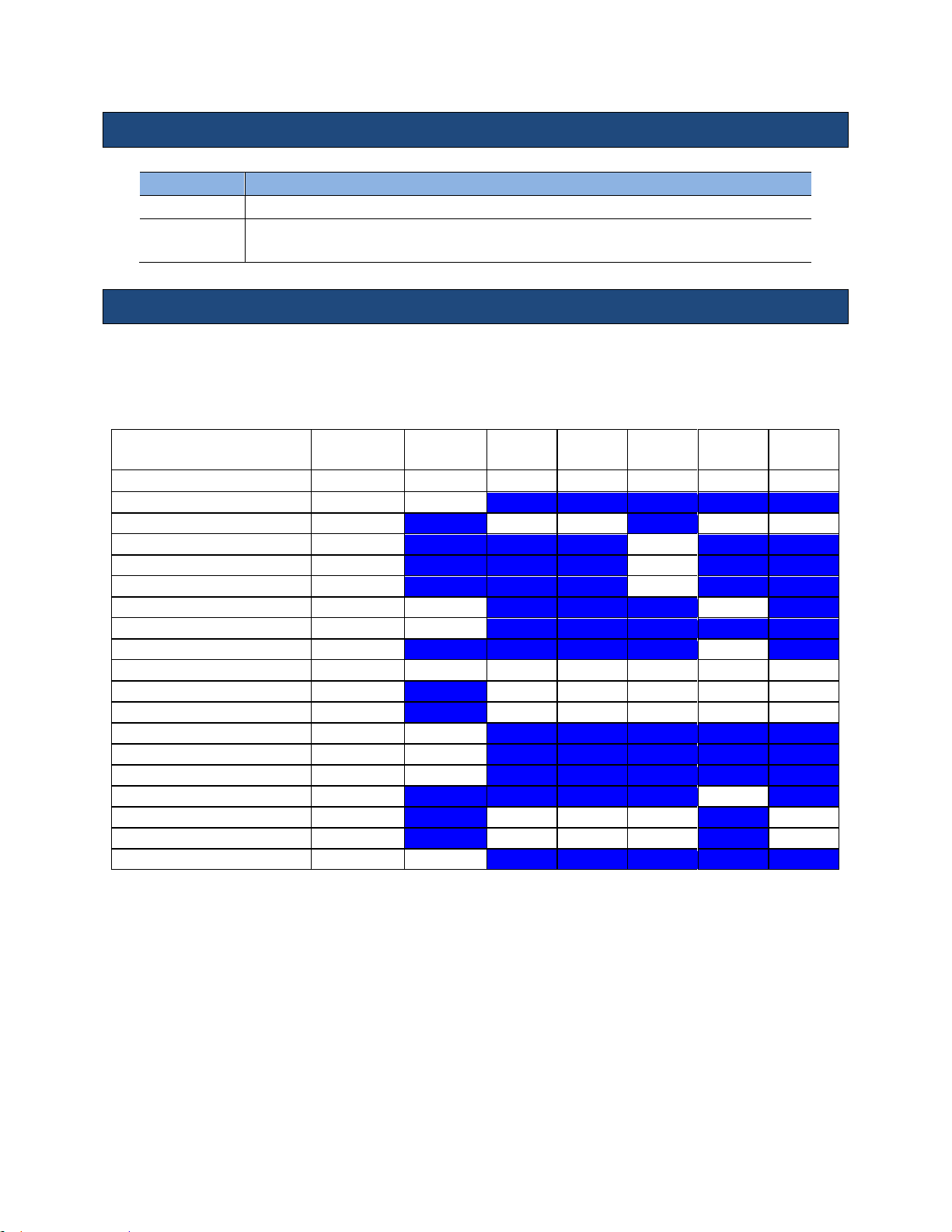
Instructions for Use
Term
Definition
(c)
This formulation for TIS is less than that for an alternate formulation in this mode.
#
No data are reported for this operating condition since the global Maximum index value
is not reported for the reason listed.
A2CW CW
MI
TIS Scan
TIS non-
scan < 1
TIS non-
scan > 1
TIB non-
scan
TIC
0.07 - -
0.56
2.70
1.32
Pr,a
[Mpa]
0.10
P
[mW] - -
84.06
84.06
min of[Pa(Zs),Ita,a(Zs)
[mW] 60.49
Zs
[cm] 2.43
Zbp
[cm] 2.43
Zb
[cm]
2.71 2.15
z at max Ipi,a
[cm]
2.43
deq(Zb)
[cm]
0.52
fawf
[cm]
1.96 - -
1.96
1.96
1.96
Dim of Aaprt X
[cm] - - 1.52
1.52
1.52
Dim of Aaprt Y
[cm] - - 1.30
1.30
1.30
TD
[usec]
4.97
PRR
[Hz]
200000
Pr at max Ipi
[Mpa]
0.11
deq at max Ipi
[cm]
0.50
FLx
[cm] - - 30.00
30.00
FLy
[cm] - - 7.50
7.50
Ipa,a at max MI
[W/cm2]
0.3
Symbols used in the tables
Acoustic Power Output Tables
The table below provides Track 3 reporting values for the specific operating modality for the
specific ZONARE transducer.
z.one
Instructions for Use, Q00350-00, Rev D 83 | P a g e
pro
Page 84
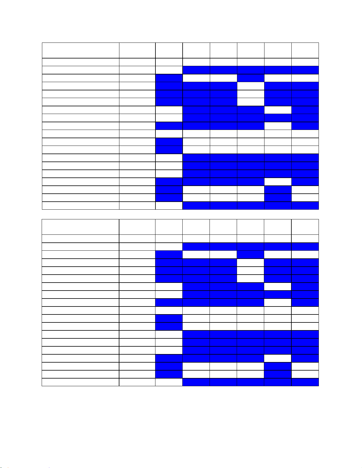
Instructions for Use
A5CW CW
MI
TIS Scan
TIS nonscan < 1
TIS nonscan > 1
TIB non-
scan
TIC
0.03 - -
0.59
2.30
0.82
Pr,a
[Mpa]
0.08
P
[mW] - -
29.30
29.30
min of[Pa(Zs),Ita,a(Zs)
[mW] 24.59
Zs
[cm] 0.50
Zbp
[cm] 0.50
Zb
[cm]
1.88 0.78
z at max Ipi,a
[cm]
1.88
deq(Zb)
[cm]
0.31
fawf
[cm]
5.08 - -
5.08
5.08
5.08
Dim of Aaprt X
[cm] - - 0.49
0.49
0.49
Dim of Aaprt Y
[cm] - - 1.30
1.30
1.30
TD
[usec]
4.96
PRR
[Hz]
200000
Pr at max Ipi
[Mpa]
0.11
deq at max Ipi
[cm]
0.30
FLx
[cm] - - 30.00
30.00
FLy
[cm] - - 7.50
7.50
Ipa,a at max MI
[W/cm2]
0.2
C4-1 B mode
MI
TIS Scan
TIS nonscan < 1
TIS nonscan > 1
TIB non-
scan
TIC
1.56
0.46 - - - 1.14
Pr,a
[Mpa]
1.97
P
[mW]
101.16 - - 101.16
min of[Pa(Zs),Ita,a(Zs)
[mW] -
Zs
[cm] -
Zbp
[cm] -
Zb
[cm]
3.74 -
z at max Ipi,a
[cm]
4.92
deq(Zb)
[cm] -
fawf
[cm]
1.60
1.60 - - - 1.60
Dim of Aaprt X
[cm] 1.20 - - - 1.20
Dim of Aaprt Y
[cm] 1.50 - - - 1.50
TD
[usec]
1.23
PRR
[Hz]
1849
Pr at max Ipi
[Mpa]
2.09
deq at max Ipi
[cm] -
FLx
[cm] 6.00 - - 6.00
FLy
[cm] 8.00 - - 8.00
Ipa,a at max MI
[W/cm2]
165.6
z.one
pro
Instructions for Use, Q00350-00, Rev D 84 | P a g e
Page 85
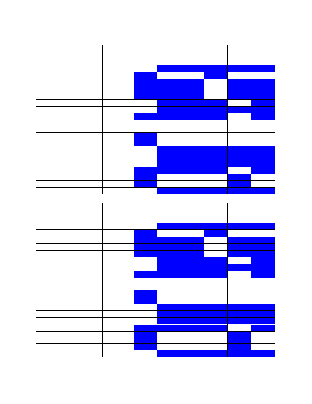
Instructions for Use
C4-1 M Mode
MI
TIS Scan
TIS nonscan < 1
TIS nonscan > 1
TIB non-
scan
TIC
1.56
0.11 - -
0.86
0.72
Pr,a
[Mpa]
1.97
P
[mW]
51.03 -
51.03
51.03
min of[Pa(Zs),Ita,a(Zs)
[mW] -
Zs
[cm] -
Zbp
[cm] -
Zb
[cm]
3.74 4.33
z at max Ipi,a
[cm]
4.92
deq(Zb)
[cm]
0.44
fawf
[cm]
1.59
1.59-
1.59 - -
1.59
1.59-
1.59
Dim of Aaprt X
[cm] 1.20 - -
1.20
1.20
Dim of Aaprt Y
[cm] 1.50 - -
1.50
1.50
TD
[usec]
1.22
PRR
[Hz]
442
Pr at max Ipi
[Mpa]
2.09
deq at max Ipi
[cm]
0.41
FLx
[cm] 6.00 - - 6.00
FLy
[cm] 8.00 - - 8.00
Ipa,a at max MI
[W/cm2]
163.9
C4-1 CD
MI
TIS Scan
TIS nonscan < 1
TIS nonscan > 1
TIB non-
scan
TIC
0.82
0.19 - - - 0.35
Pr,a
[Mpa]
1.04
P
[mW]
30.02 - - 30.02
min of[Pa(Zs),Ita,a(Zs)
[mW] -
Zs
[cm] -
Zbp
[cm] -
Zb
[cm]
4.04 -
z at max Ipi,a
[cm]
4.63
deq(Zb)
[cm] -
fawf
[cm]
1.60
1.60-
2.27 - -
-
1.60-
2.27
Dim of Aaprt X
[cm] 1.60 - - - 1.60
Dim of Aaprt Y
[cm] 1.50 - - - 1.50
TD
[usec]
1.23
PRR
[Hz]
630
Pr at max Ipi
[Mpa]
1.25
deq at max Ipi
[cm] -
FLx
[cm]
6.0-
12.0 - -
6.0-
12.0
FLy
[cm] 8.00 - - 8.00
Ipa,a at max MI
[W/cm2]
39.0
z.one
pro
Instructions for Use, Q00350-00, Rev D 85 | P a g e
Page 86

Instructions for Use
C4-1 PW
MI
TIS Scan
TIS nonscan < 1
TIS nonscan > 1
TIB non-
scan
TIC
1.56
( c )
0.46
-
2.27
1.28
Pr,a
[Mpa]
1.97
P
[mW] #
101.16
63.30
63.30
min of[Pa(Zs),Ita,a(Zs)
[mW] -
Zs
[cm] -
Zbp
[cm] -
Zb
[cm]
3.74 2.27
z at max Ipi,a
[cm]
4.92
deq(Zb)
[cm]
0.43
fawf
[cm]
1.60
#
1.60
-
2.51
2.51
Dim of Aaprt X
[cm] #
1.20
-
0.80
0.80
Dim of Aaprt Y
[cm] #
1.50
-
1.50
1.50
TD
[usec]
1.23
PRR
[Hz]
1849
Pr at max Ipi
[Mpa]
2.09
deq at max Ipi
[cm]
0.42
FLx
[cm] #
6.00 -
3.00
FLy
[cm] #
8.00 -
8.00
Ipa,a at max MI
[W/cm2]
165.6
C4-1 CW
MI
TIS Scan
TIS nonscan < 1
TIS nonscan > 1
TIB non-
scan
TIC
0.10 - -
0.26
4.07
0.70
Pr,a
[Mpa]
0.13
P
[mW] - -
47.10
47.10
min of[Pa(Zs),Ita,a(Zs)
[mW] 37.34
Zs
[cm] 2.27
Zbp
[cm] 2.27
Zb
[cm]
3.74 3.74
z at max Ipi,a
[cm]
3.74
deq(Zb)
[cm]
0.28
fawf
[cm]
1.48 - -
1.48
1.48
1.48
Dim of Aaprt X
[cm] - - 1.50
1.50
1.50
Dim of Aaprt Y
[cm] - - 1.50
1.50
1.50
TD
[usec]
10.00
PRR
[Hz]
100000
Pr at max Ipi
[Mpa]
0.15
deq at max Ipi
[cm]
0.28
FLx
[cm] - - 9.00
9.00
FLy
[cm] - - 8.00
8.00
Ipa,a at max MI
[W/cm2]
0.5
z.one
pro
Instructions for Use, Q00350-00, Rev D 86 | P a g e
Page 87
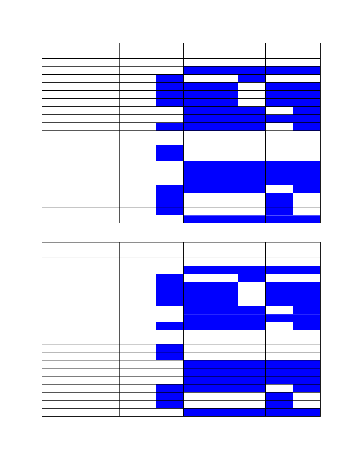
Instructions for Use
C4-1 CDT
MI
TIS Scan
TIS nonscan < 1
TIS nonscan > 1
TIB non-
scan
TIC
0.82
0.19
-
0.54
2.27
1.28
Pr,a
[Mpa]
1.04
P
[mW]
30.02 -
63.30
63.30
min of[Pa(Zs),Ita,a(Zs)
[mW] 44.97
Zs
[cm] 1.97
Zbp
[cm] 1.97
Zb
[cm]
4.04 2.27
z at max Ipi,a
[cm]
4.63
deq(Zb)
[cm]
0.43
fawf
[cm]
1.60
1.60-
2.27
-
2.51
2.51
2.51
Dim of Aaprt X
[cm] 1.60
-
0.80
0.80
0.80
Dim of Aaprt Y
[cm] 1.50
-
1.50
1.50
1.50
TD
[usec]
1.23
PRR
[Hz]
630
Pr at max Ipi
[Mpa]
1.25
deq at max Ipi
[cm]
0.42
FLx
[cm]
6.0-
12.0
-
3.00
3.00
FLy
[cm] 8.00
-
8.00
8.00
Ipa,a at max MI
[W/cm2]
39.0
C6-2 B mode
MI
TIS Scan
TIS nonscan < 1
TIS nonscan > 1
TIB non-
scan
TIC
1.33
0.65 - - - 1.15
Pr,a
[Mpa]
2.00
P
[mW]
97.46 - - 97.46
min of[Pa(Zs),Ita,a(Zs)
[mW] -
Zs
[cm] -
Zbp
[cm] -
Zb
[cm]
3.74 -
z at max Ipi,a
[cm]
4.63
deq(Zb)
[cm] -
fawf
[cm]
2.26
2.26-
3.38 - -
-
2.26-
3.38
Dim of Aaprt X
[cm] 1.08 - - - 1.08
Dim of Aaprt Y
[cm] 1.20 - - - 1.20
TD
[usec]
0.96
PRR
[Hz]
882
Pr at max Ipi
[Mpa]
2.51
deq at max Ipi
[cm] -
FLx
[cm] 9.00 - - 9.00
FLy
[cm] 7.00 - - 7.00
Ipa,a at max MI
[W/cm2]
133.3
z.one
pro
Instructions for Use, Q00350-00, Rev D 87 | P a g e
Page 88
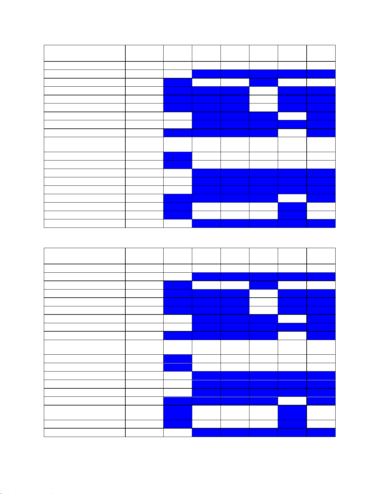
Instructions for Use
C6-2 M mode
MI
TIS Scan
TIS nonscan < 1
TIS nonscan > 1
TIB non-
scan
TIC
1.38
0.11
-
0.22
0.79
0.88
Pr,a
[Mpa]
1.99
P
[mW]
55.42 -
55.42
55.42
min of[Pa(Zs),Ita,a(Zs)
[mW] 22.68
Zs
[cm] 1.97
Zbp
[cm] 1.97
Zb
[cm]
3.74 4.33
z at max Ipi,a
[cm]
4.63
deq(Zb)
[cm]
0.46
fawf
[cm]
2.08
2.08-
2.08
-
2.08
2.08
2.08-
2.08
Dim of Aaprt X
[cm] 1.08
-
1.08
1.08
1.08
Dim of Aaprt Y
[cm] 1.20
-
1.20
1.20
1.20
TD
[usec]
1.09
PRR
[Hz]
403
Pr at max Ipi
[Mpa]
2.30
deq at max Ipi
[cm]
0.44
FLx
[cm] 9.00
-
9.00
9.00
FLy
[cm] 7.00
-
7.00
7.00
Ipa,a at max MI
[W/cm2]
157.1
C6-2 CD
MI
TIS Scan
TIS nonscan < 1
TIS nonscan > 1
TIB non-
scan
TIC
1.33
0.45 - - - 0.74
Pr,a
[Mpa]
1.92
P
[mW]
60.66 - - 60.66
min of[Pa(Zs),Ita,a(Zs)
[mW] -
Zs
[cm] -
Zbp
[cm] -
Zb
[cm]
3.74 -
z at max Ipi,a
[cm]
4.63
deq(Zb)
[cm] -
fawf
[cm]
2.08
2.08-
3.38 - -
-
2.08-
3.38
Dim of Aaprt X
[cm] 1.08 - - - 1.08
Dim of Aaprt Y
[cm] 1.20 - - - 1.20
TD
[usec]
1.08
PRR
[Hz]
420
Pr at max Ipi
[Mpa]
2.30
deq at max Ipi
[cm] -
FLx
[cm]
9.0-
12.0 - -
9.0-
12.0
FLy
[cm] 7.00 - - 7.00
Ipa,a at max MI
[W/cm2]
145.6
z.one
pro
Instructions for Use, Q00350-00, Rev D 88 | P a g e
Page 89
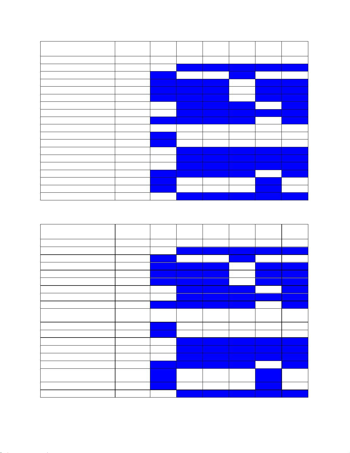
Instructions for Use
C6-2 PW
MI
TIS Scan
TIS nonscan < 1
TIS nonscan > 1
TIB non-
scan
TIC
1.33
( c )
-
1.23
3.02
2.34
Pr,a
[Mpa]
2.00
P
[mW] # -
129.73
129.73
min of[Pa(Zs),Ita,a(Zs)
[mW] 86.12
Zs
[cm] 1.97
Zbp
[cm] 1.97
Zb
[cm]
3.74 4.92
z at max Ipi,a
[cm]
4.63
deq(Zb)
[cm]
0.35
fawf
[cm]
2.26 # -
3.00
3.00
3.00
Dim of Aaprt X
[cm] # - 1.26
1.26
1.26
Dim of Aaprt Y
[cm] # - 1.20
1.20
1.20
TD
[usec]
0.96
PRR
[Hz]
882
Pr at max Ipi
[Mpa]
2.51
deq at max Ipi
[cm]
0.32
FLx
[cm] # - 5.00
5.00
FLy
[cm] # - 7.00
7.00
Ipa,a at max MI
[W/cm2]
133.3
C6-2 CDT
MI
TIS Scan
TIS nonscan < 1
TIS nonscan > 1
TIB non-
scan
TIC
1.33
0.45
-
1.23
3.02
2.34
Pr,a
[Mpa]
1.92
P
[mW]
60.66 -
129.73
129.73
min of[Pa(Zs),Ita,a(Zs)
[mW] 86.12
Zs
[cm] 1.97
Zbp
[cm] 1.97
Zb
[cm]
3.74 4.92
z at max Ipi,a
[cm]
4.63
deq(Zb)
[cm]
0.35
fawf
[cm]
2.08
2.08-
3.38
-
3.00
3.00
3.00
Dim of Aaprt X
[cm] 1.08
-
1.26
1.26
1.26
Dim of Aaprt Y
[cm] 1.20
-
1.20
1.20
1.20
TD
[usec]
1.08
PRR
[Hz]
420
Pr at max Ipi
[Mpa]
2.30
deq at max Ipi
[cm]
0.32
FLx
[cm]
9.0-
12.0
-
5.00
5.00
FLy
[cm] 7.00
-
7.00
7.00
Ipa,a at max MI
[W/cm2]
145.6
z.one
pro
Instructions for Use, Q00350-00, Rev D 89 | P a g e
Page 90
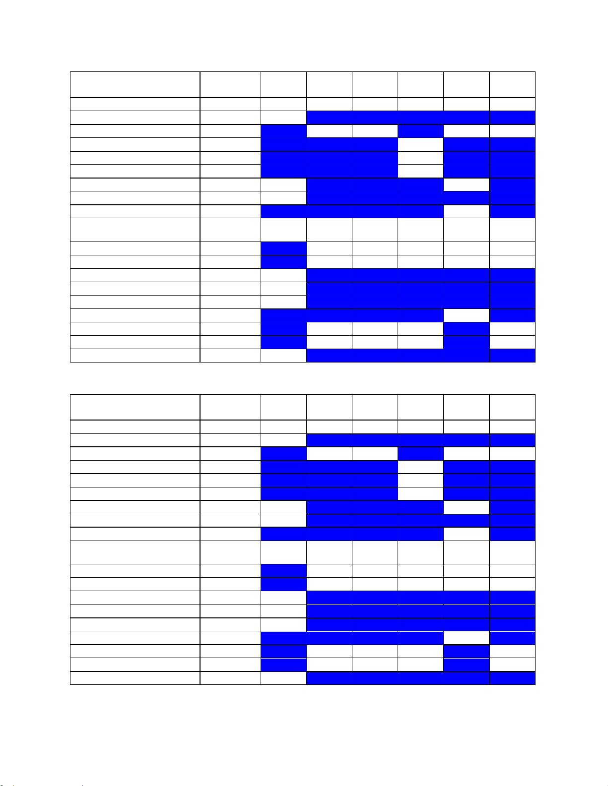
Instructions for Use
C8-3 3D B mode
MI
TIS Scan
TIS nonscan < 1
TIS nonscan > 1
TIB non-
scan
TIC
1.49
0.51 - - - 1.11
Pr,a
[Mpa]
2.36
P
[mW]
90.05 - - 90.05
min of[Pa(Zs),Ita,a(Zs)
[mW] -
Zs
[cm] -
Zbp
[cm] -
Zb
[cm]
2.86 -
z at max Ipi,a
[cm]
3.45
deq(Zb)
[cm] -
fawf
[cm]
2.52
2.20-
2.52 - -
-
2.20-
2.52
Dim of Aaprt X
[cm] 1.01 - - - 1.01
Dim of Aaprt Y
[cm] 1.10 - - - 1.10
TD
[usec]
1.04
PRR
[Hz]
1515
Pr at max Ipi
[Mpa]
2.89
deq at max Ipi
[cm] -
FLx
[cm] 9.00 - - 9.00
FLy
[cm] 5.00 - - 5.00
Ipa,a at max MI
[W/cm2]
240.7
C8-3 3D M mode
MI
TIS Scan
TIS nonscan < 1
TIS nonscan > 1
TIB non-
scan
TIC
1.53
0.10
-
0.18
0.80
0.60
Pr,a
[Mpa]
2.42
P
[mW]
35.41 -
35.41
35.41
min of[Pa(Zs),Ita,a(Zs)
[mW] 15.23
Zs
[cm] 1.38
Zbp
[cm] 1.38
Zb
[cm]
2.56 3.15
z at max Ipi,a
[cm]
3.45
deq(Zb)
[cm]
0.32
fawf
[cm]
2.51
2.51-
2.51
-
2.51
2.51
2.51-
2.51
Dim of Aaprt X
[cm] 1.01
-
1.01
1.01
1.01
Dim of Aaprt Y
[cm] 1.10
-
1.10
1.10
1.10
TD
[usec]
1.05
PRR
[Hz]
480
Pr at max Ipi
[Mpa]
3.03
deq at max Ipi
[cm]
0.31
FLx
[cm] 9.00
-
9.00
9.00
FLy
[cm] 5.00
-
5.00
5.00
Ipa,a at max MI
[W/cm2]
194.6
z.one
Instructions for Use, Q00350-00, Rev D 90 | P a g e
pro
Page 91

Instructions for Use
C8-3 3D CD
MI
TIS Scan
TIS nonscan < 1
TIS nonscan > 1
TIB non-
scan
TIC
1.26
0.49 - - - 0.82
Pr,a
[Mpa]
2.00
P
[mW]
64.52 - - 64.52
min of[Pa(Zs),Ita,a(Zs)
[mW] -
Zs
[cm] -
Zbp
[cm] -
Zb
[cm]
2.86 -
z at max Ipi,a
[cm]
3.45
deq(Zb)
[cm] -
fawf
[cm]
2.53
2.53-
2.75 - -
-
2.53-
2.75
Dim of Aaprt X
[cm] 1.34 - - - 1.34
Dim of Aaprt Y
[cm] 1.10 - - - 1.10
TD
[usec]
1.01
PRR
[Hz]
378
Pr at max Ipi
[Mpa]
2.30
deq at max Ipi
[cm] -
FLx
[cm]
9.0-
24.0 - -
9.0-
24.0
FLy
[cm] 5.00 - - 5.00
Ipa,a at max MI
[W/cm2]
148.2
C8-3 3D PW
MI
TIS Scan
TIS nonscan < 1
TIS nonscan > 1
TIB non-
scan
TIC
1.49
( c )
0.51
-
1.68
1.11
Pr,a
[Mpa]
2.36
P
[mW] #
90.05
32.24
90.05
min of[Pa(Zs),Ita,a(Zs)
[mW] -
Zs
[cm] -
Zbp
[cm] -
Zb
[cm]
2.86 3.15
z at max Ipi,a
[cm]
3.45
deq(Zb)
[cm]
0.23
fawf
[cm]
2.52
#
2.20-
2.52
-
2.98
2.20-
2.52
Dim of Aaprt X
[cm] #
1.01
-
1.01
1.01
Dim of Aaprt Y
[cm] #
1.10
-
1.10
1.10
TD
[usec]
1.04
PRR
[Hz]
1515
Pr at max Ipi
[Mpa]
2.89
deq at max Ipi
[cm]
0.22
FLx
[cm] #
9.00 -
9.00
FLy
[cm] #
5.00 -
5.00
Ipa,a at max MI
[W/cm2]
240.7
z.one
pro
Instructions for Use, Q00350-00, Rev D 91 | P a g e
Page 92

Instructions for Use
C8-3 3D CDT
MI
TIS Scan
TIS nonscan < 1
TIS nonscan > 1
TIB non-
scan
TIC
1.26
0.49 - -
1.68
0.82
Pr,a
[Mpa]
2.00
P
[mW]
64.52 -
32.24
64.52
min of[Pa(Zs),Ita,a(Zs)
[mW] -
Zs
[cm] -
Zbp
[cm] -
Zb
[cm]
2.86 3.15
z at max Ipi,a
[cm]
3.45
deq(Zb)
[cm]
0.23
fawf
[cm]
2.53
2.53-
2.75 - -
2.98
2.53-
2.75
Dim of Aaprt X
[cm] 1.34 - -
1.01
1.34
Dim of Aaprt Y
[cm] 1.10 - -
1.10
1.10
TD
[usec]
1.01
PRR
[Hz]
378
Pr at max Ipi
[Mpa]
2.30
deq at max Ipi
[cm]
0.22
FLx
[cm]
9.0-
24.0 - -
9.0-
24.0
FLy
[cm] 5.00 - - 5.00
Ipa,a at max MI
[W/cm2]
148.2
C9-3 B mode
MI
TIS Scan
TIS nonscan < 1
TIS nonscan > 1
TIB non-
scan
TIC
1.86
0.84 - - - 1.33
Pr,a
[Mpa]
3.17
P
[mW]
78.19 - - 78.19
min of[Pa(Zs),Ita,a(Zs)
[mW] -
Zs
[cm] -
Zbp
[cm] -
Zb
[cm]
1.96 -
z at max Ipi,a
[cm]
2.45
deq(Zb)
[cm] -
fawf
[cm]
2.89
2.89-
4.17 - -
-
2.89-
4.17
Dim of Aaprt X
[cm] 0.72 - - - 0.72
Dim of Aaprt Y
[cm] 0.80 - - - 0.80
TD
[usec]
0.69
PRR
[Hz]
1929
Pr at max Ipi
[Mpa]
3.39
deq at max Ipi
[cm] -
FLx
[cm] 5.00 - - 5.00
FLy
[cm] 4.50 - - 4.50
Ipa,a at max MI
[W/cm2]
392.2
z.one
pro
Instructions for Use, Q00350-00, Rev D 92 | P a g e
Page 93
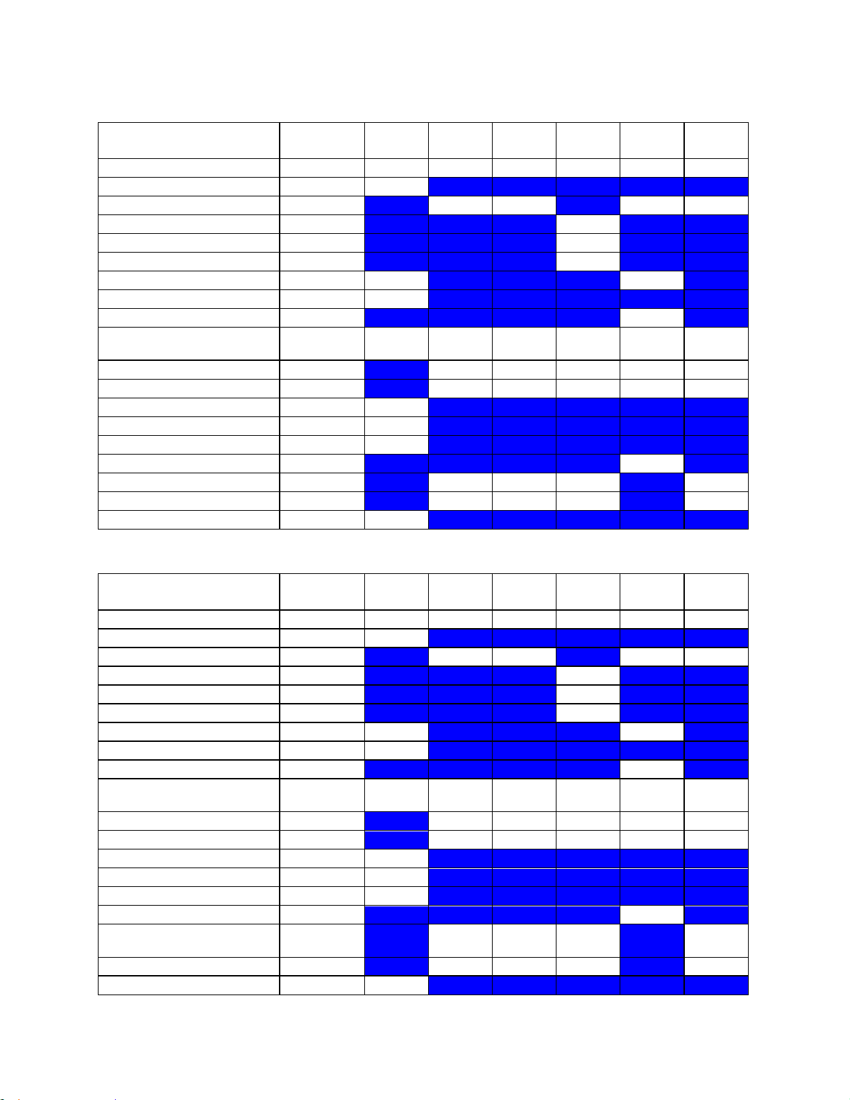
Instructions for Use
C9-3 M mode
MI
TIS Scan
TIS nonscan < 1
TIS nonscan > 1
TIB non-
scan
TIC
1.39
0.15 - -
0.32
0.48
Pr,a
[Mpa]
2.83
P
[mW]
16.57 -
16.57
16.57
min of[Pa(Zs),Ita,a(Zs)
[mW] -
Zs
[cm] -
Zbp
[cm] -
Zb
[cm]
2.21 2.69
z at max Ipi,a
[cm]
2.69
deq(Zb)
[cm]
0.29
fawf
[cm]
4.15
4.15-
4.15 - -
4.15
4.15-
4.15
Dim of Aaprt X
[cm] 0.72 - -
0.72
0.72
Dim of Aaprt Y
[cm] 0.80 - -
0.80
0.80
TD
[usec]
0.49
PRR
[Hz]
403
Pr at max Ipi
[Mpa]
3.47
deq at max Ipi
[cm]
0.29
FLx
[cm] 5.00 - - 5.00
FLy
[cm] 4.50 - - 4.50
Ipa,a at max MI
[W/cm2]
193.2
C9-3 CD
MI
TIS Scan
TIS nonscan < 1
TIS nonscan > 1
TIB non-
scan
TIC
1.16
0.98 - - - 1.02
Pr,a
[Mpa]
2.38
P
[mW]
57.41 - - 57.41
min of[Pa(Zs),Ita,a(Zs)
[mW] -
Zs
[cm] -
Zbp
[cm] -
Zb
[cm]
2.21 -
z at max Ipi,a
[cm]
2.69
deq(Zb)
[cm] -
fawf
[cm]
4.19
4.19-
4.97 - -
-
4.19-
4.97
Dim of Aaprt X
[cm] 0.96 - - - 0.96
Dim of Aaprt Y
[cm] 0.80 - - - 0.80
TD
[usec]
0.48
PRR
[Hz]
420
Pr at max Ipi
[Mpa]
3.06
deq at max Ipi
[cm] -
FLx
[cm]
5.0-
18.0 - -
5.0-
18.0
FLy
[cm] 4.50 - - 4.50
Ipa,a at max MI
[W/cm2]
133.1
z.one
pro
Instructions for Use, Q00350-00, Rev D 93 | P a g e
Page 94
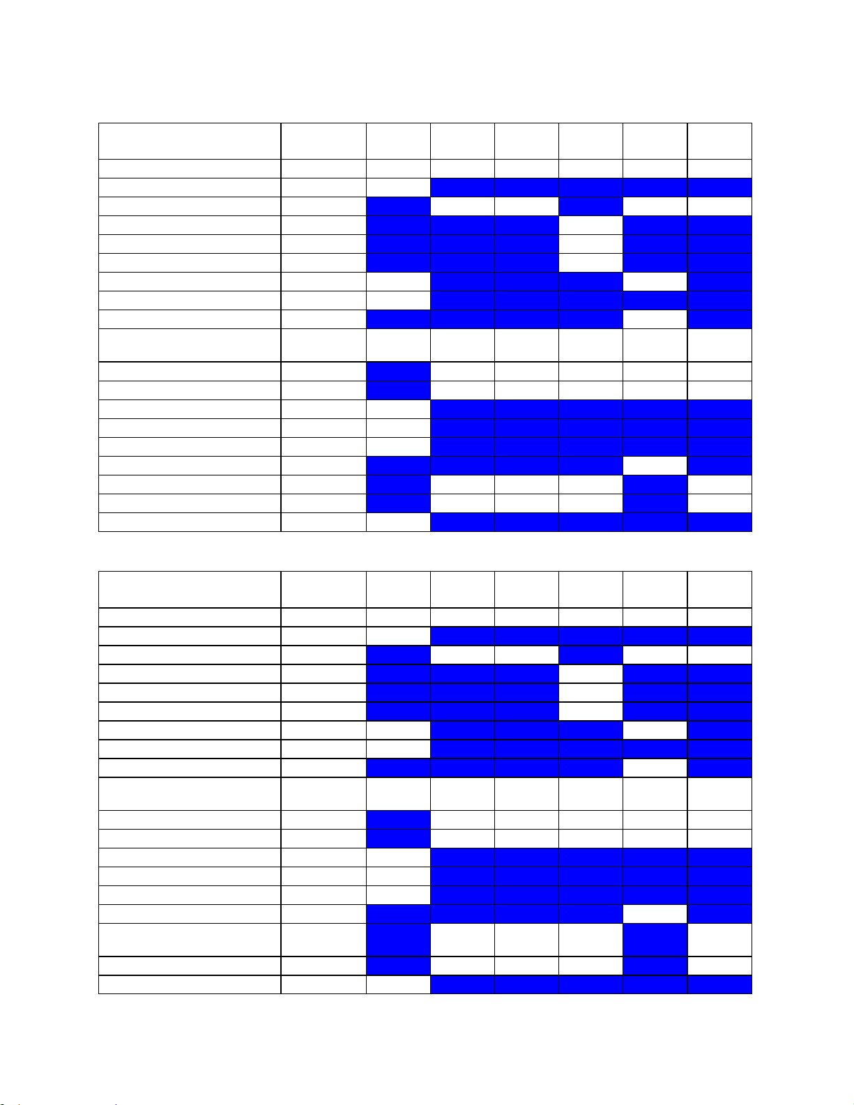
Instructions for Use
C9-3 PW
MI
TIS Scan
TIS nonscan < 1
TIS nonscan > 1
TIB non-
scan
TIC
1.86
( c )
0.84
-
1.99
1.33
Pr,a
[Mpa]
3.17
P
[mW] #
78.19
32.74
78.19
min of[Pa(Zs),Ita,a(Zs)
[mW] -
Zs
[cm] -
Zbp
[cm] -
Zb
[cm]
1.96 0.99
z at max Ipi,a
[cm]
2.45
deq(Zb)
[cm]
0.30
fawf
[cm]
2.89
#
2.89-
4.17
-
3.16
2.89-
4.17
Dim of Aaprt X
[cm] #
0.72
-
0.51
0.72
Dim of Aaprt Y
[cm] #
0.80
-
0.80
0.80
TD
[usec]
0.69
PRR
[Hz]
1929
Pr at max Ipi
[Mpa]
3.39
deq at max Ipi
[cm]
0.24
FLx
[cm] #
5.00 -
5.00
FLy
[cm] #
4.50 -
4.50
Ipa,a at max MI
[W/cm2]
392.2
C9-3 CDT
MI
TIS Scan
TIS nonscan < 1
TIS nonscan > 1
TIB non-
scan
TIC
1.16
0.98 - -
1.99
1.14
Pr,a
[Mpa]
2.38
P
[mW]
57.41 -
32.74
32.74
min of[Pa(Zs),Ita,a(Zs)
[mW] -
Zs
[cm] -
Zbp
[cm] -
Zb
[cm]
2.21 0.99
z at max Ipi,a
[cm]
2.69
deq(Zb)
[cm]
0.30
fawf
[cm]
4.19
4.19-
4.97 - -
3.16
3.16
Dim of Aaprt X
[cm] 0.96 - -
0.51
0.51
Dim of Aaprt Y
[cm] 0.80 - -
0.80
0.80
TD
[usec]
0.48
PRR
[Hz]
420
Pr at max Ipi
[Mpa]
3.06
deq at max Ipi
[cm]
0.24
FLx
[cm]
5.0-
18.0 - - 2.00
FLy
[cm] 4.50 - - 4.50
Ipa,a at max MI
[W/cm2]
133.1
z.one
pro
Instructions for Use, Q00350-00, Rev D 94 | P a g e
Page 95
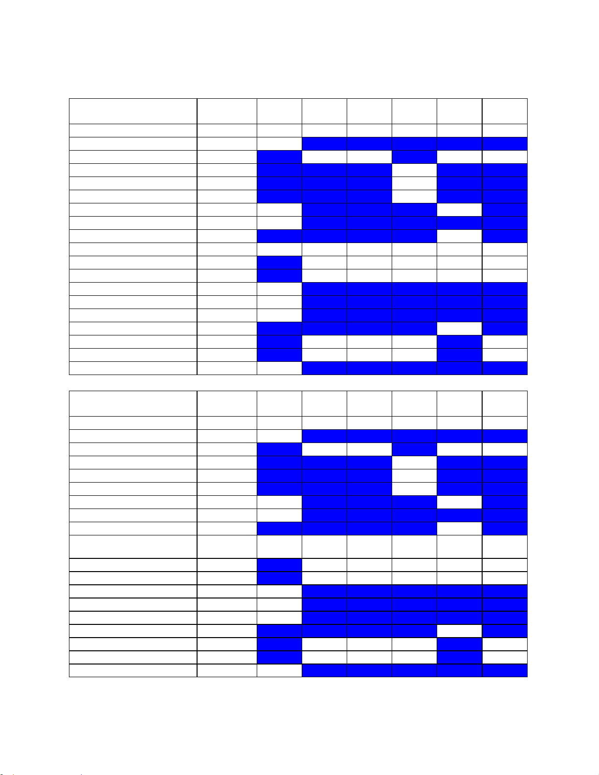
Instructions for Use
C9-3sp B mode
MI
TIS Scan
TIS nonscan < 1
TIS nonscan > 1
TIB non-
scan
TIC
1.43
0.48 - - - 0.98
Pr,a
[Mpa]
2.43
P
[mW]
60.58 - - 60.58
min of[Pa(Zs),Ita,a(Zs)
[mW] -
Zs
[cm] -
Zbp
[cm] -
Zb
[cm]
1.94 -
z at max Ipi,a
[cm]
2.54
deq(Zb)
[cm] -
fawf
[cm]
2.88
2.88 - - - 2.88
Dim of Aaprt X
[cm] 0.72 - - - 0.72
Dim of Aaprt Y
[cm] 0.80 - - - 0.80
TD
[usec]
0.69
PRR
[Hz]
3964
Pr at max Ipi
[Mpa]
2.88
deq at max Ipi
[cm] -
FLx
[cm] 5.00 - - 5.00
FLy
[cm] 4.50 - - 4.50
Ipa,a at max MI
[W/cm2]
287.5
C9-3sp M mode
MI
TIS Scan
TIS nonscan < 1
TIS nonscan > 1
TIB non-
scan
TIC
1.40
0.12 - -
0.90
0.67
Pr,a
[Mpa]
2.37
P
[mW]
29.36 -
29.36
29.36
min of[Pa(Zs),Ita,a(Zs)
[mW] -
Zs
[cm] -
Zbp
[cm] -
Zb
[cm]
1.94 2.30
z at max Ipi,a
[cm]
2.54
deq(Zb)
[cm]
0.23
fawf
[cm]
2.88
2.88-
2.88 - -
2.88
2.88-
2.88
Dim of Aaprt X
[cm] 0.72 - -
0.72
0.72
Dim of Aaprt Y
[cm] 0.80 - -
0.80
0.80
TD
[usec]
0.69
PRR
[Hz]
960
Pr at max Ipi
[Mpa]
2.75
deq at max Ipi
[cm]
0.22
FLx
[cm] 5.00 - - 5.00
FLy
[cm] 4.50 - - 4.50
Ipa,a at max MI
[W/cm2]
275.1
z.one
pro
Instructions for Use, Q00350-00, Rev D 95 | P a g e
Page 96

Instructions for Use
C9-3sp CD
MI
TIS Scan
TIS nonscan < 1
TIS nonscan > 1
TIB non-
scan
TIC
1.27
0.45 - - - 0.58
Pr,a
[Mpa]
2.16
P
[mW]
32.62 - - 32.62
min of[Pa(Zs),Ita,a(Zs)
[mW] -
Zs
[cm] -
Zbp
[cm] -
Zb
[cm]
2.18 -
z at max Ipi,a
[cm]
2.54
deq(Zb)
[cm] -
fawf
[cm]
2.89
2.89-
4.20 - -
-
2.89-
4.20
Dim of Aaprt X
[cm] 0.96 - - - 0.96
Dim of Aaprt Y
[cm] 0.80 - - - 0.80
TD
[usec]
0.67
PRR
[Hz]
420
Pr at max Ipi
[Mpa]
2.42
deq at max Ipi
[cm] -
FLx
[cm]
5.0-
18.0 - -
5.0-
18.0
FLy
[cm] 4.50 - - 4.50
Ipa,a at max MI
[W/cm2]
249.0
C9-3sp PW
MI
TIS Scan
TIS nonscan < 1
TIS nonscan > 1
TIB non-
scan
TIC
1.43
( c )
0.48
-
1.60
0.98
Pr,a
[Mpa]
2.43
P
[mW] #
60.58
26.65
60.58
min of[Pa(Zs),Ita,a(Zs)
[mW] -
Zs
[cm] -
Zbp
[cm] -
Zb
[cm]
1.94 2.78
z at max Ipi,a
[cm]
2.54
deq(Zb)
[cm]
0.21
fawf
[cm]
2.88
#
2.88
-
3.15
2.88
Dim of Aaprt X
[cm] #
0.72
-
1.02
0.72
Dim of Aaprt Y
[cm] #
0.80
-
0.80
0.80
TD
[usec]
0.69
PRR
[Hz]
3964
Pr at max Ipi
[Mpa]
2.88
deq at max Ipi
[cm]
0.20
FLx
[cm] #
5.00 -
5.00
FLy
[cm] #
4.50 -
4.50
Ipa,a at max MI
[W/cm2]
287.5
z.one
pro
Instructions for Use, Q00350-00, Rev D 96 | P a g e
Page 97
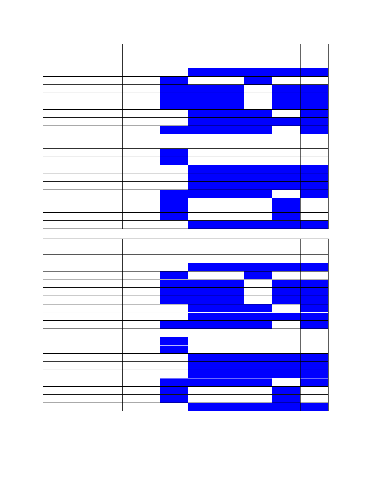
Instructions for Use
C9-3sp CDT
MI
TIS Scan
TIS nonscan < 1
TIS nonscan > 1
TIB non-
scan
TIC
1.27
0.45 - -
1.60
0.65
Pr,a
[Mpa]
2.16
P
[mW]
32.62 -
26.65
26.65
min of[Pa(Zs),Ita,a(Zs)
[mW] -
Zs
[cm] -
Zbp
[cm] -
Zb
[cm]
2.18 2.78
z at max Ipi,a
[cm]
2.54
deq(Zb)
[cm]
0.21
fawf
[cm]
2.89
2.89-
4.20 - -
3.15
3.15
Dim of Aaprt X
[cm] 0.96 - -
1.02
1.02
Dim of Aaprt Y
[cm] 0.80 - -
0.80
0.80
TD
[usec]
0.67
PRR
[Hz]
420
Pr at max Ipi
[Mpa]
2.42
deq at max Ipi
[cm]
0.20
FLx
[cm]
5.0-
18.0 - - 4.00
FLy
[cm] 4.50 - - 4.50
Ipa,a at max MI
[W/cm2]
249.0
C10-3 B mode
MI
TIS Scan
TIS nonscan < 1
TIS nonscan > 1
TIB non-
scan
TIC
1.58
0.71 - - - 0.64
Pr,a
[Mpa]
3.05
P
[mW]
26.56 - - 26.56
min of[Pa(Zs),Ita,a(Zs)
[mW] -
Zs
[cm] -
Zbp
[cm] -
Zb
[cm]
1.50 -
z at max Ipi,a
[cm]
1.83
deq(Zb)
[cm] -
fawf
[cm]
3.75
6.14 - - - 6.14
Dim of Aaprt X
[cm] 0.77 - - - 0.77
Dim of Aaprt Y
[cm] 0.60 - - - 0.60
TD
[usec]
0.58
PRR
[Hz]
783
Pr at max Ipi
[Mpa]
3.57
deq at max Ipi
[cm] -
FLx
[cm] 5.00 - - 5.00
FLy
[cm] 3.50 - - 3.50
Ipa,a at max MI
[W/cm2]
390.9
z.one
pro
Instructions for Use, Q00350-00, Rev D 97 | P a g e
Page 98
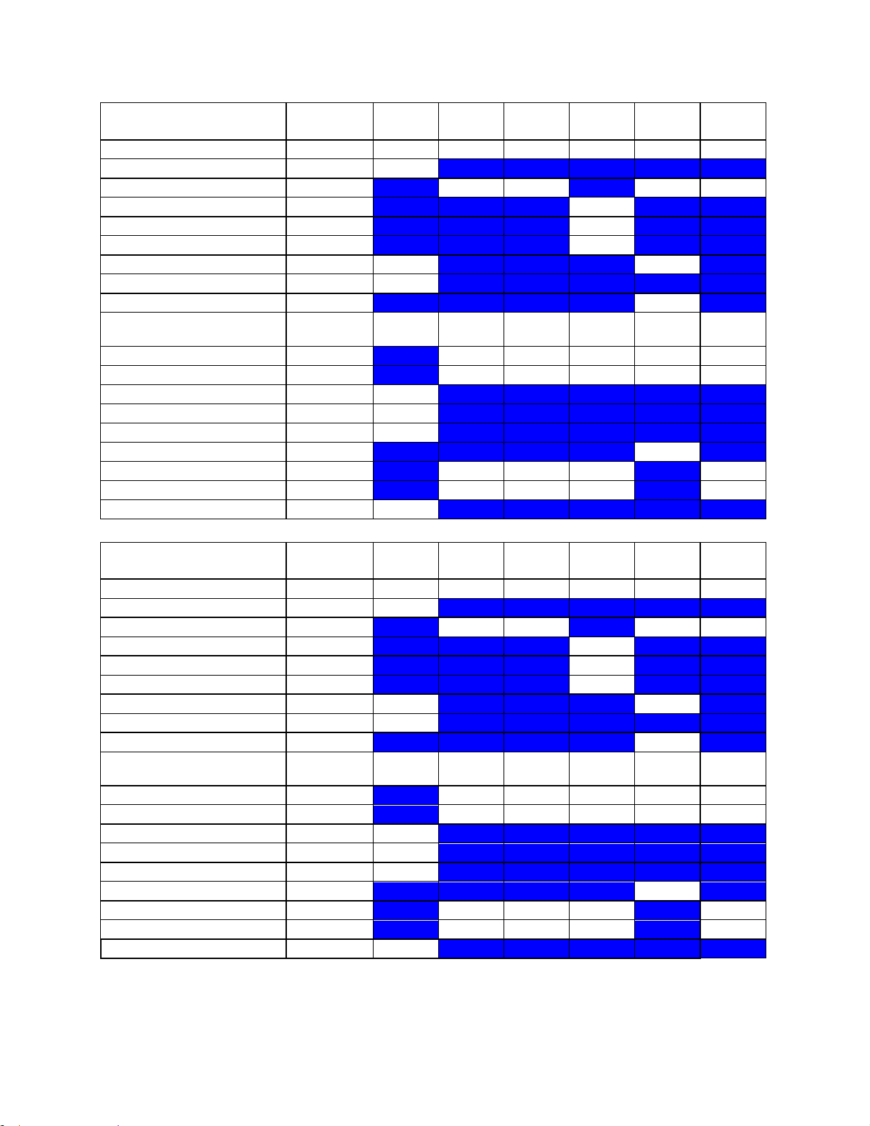
Instructions for Use
C10-3 M mode
MI
TIS Scan
TIS nonscan < 1
TIS nonscan > 1
TIB non-
scan
TIC
1.54
0.10
0.23
-
0.44
0.37
Pr,a
[Mpa]
3.06
P
[mW]
12.70
12.70
12.70
12.70
min of[Pa(Zs),Ita,a(Zs)
[mW] -
Zs
[cm] -
Zbp
[cm] -
Zb
[cm]
1.50 1.67
z at max Ipi,a
[cm]
1.83
deq(Zb)
[cm]
0.22
fawf
[cm]
3.96
3.96-
3.96
3.96-
3.96
-
3.96
3.96-
3.96
Dim of Aaprt X
[cm] 0.77
0.77
-
0.77
0.77
Dim of Aaprt Y
[cm] 0.60
0.60
-
0.60
0.60
TD
[usec]
0.42
PRR
[Hz]
480
Pr at max Ipi
[Mpa]
3.89
deq at max Ipi
[cm]
0.21
FLx
[cm] 5.00
5.00 -
5.00
FLy
[cm] 3.50
3.50 -
3.50
Ipa,a at max MI
[W/cm2]
505.5
C10-3 CD
MI
TIS Scan
TIS nonscan < 1
TIS nonscan > 1
TIB non-
scan
TIC
1.52
0.74 - - - 0.79
Pr,a
[Mpa]
3.03
P
[mW]
27.89 - - 27.89
min of[Pa(Zs),Ita,a(Zs)
[mW] -
Zs
[cm] -
Zbp
[cm] -
Zb
[cm]
1.83 -
z at max Ipi,a
[cm]
1.83
deq(Zb)
[cm] -
fawf
[cm]
3.96
3.96-
6.06 - -
-
3.96-
6.06
Dim of Aaprt X
[cm] 0.77 - - - 0.77
Dim of Aaprt Y
[cm] 0.60 - - - 0.60
TD
[usec]
0.40
PRR
[Hz]
420
Pr at max Ipi
[Mpa]
3.76
deq at max Ipi
[cm] -
FLx
[cm] 5.00 - - 5.00
FLy
[cm] 3.50 - - 3.50
Ipa,a at max MI
[W/cm2]
576.4
z.one
pro
Instructions for Use, Q00350-00, Rev D 98 | P a g e
Page 99

Instructions for Use
C10-3 PW
MI
TIS Scan
TIS nonscan < 1
TIS nonscan > 1
TIB non-
scan
TIC
1.58
( c )
0.71
-
1.14
0.64
Pr,a
[Mpa]
3.05
P
[mW] #
26.56
16.22
26.56
min of[Pa(Zs),Ita,a(Zs)
[mW] -
Zs
[cm] -
Zbp
[cm] -
Zb
[cm]
1.50 2.17
z at max Ipi,a
[cm]
1.83
deq(Zb)
[cm]
0.19
fawf
[cm]
3.75
#
6.14
-
3.63
6.14
Dim of Aaprt X
[cm] #
0.77
-
1.01
0.77
Dim of Aaprt Y
[cm] #
0.60
-
0.60
0.60
TD
[usec]
0.58
PRR
[Hz]
783
Pr at max Ipi
[Mpa]
3.57
deq at max Ipi
[cm]
0.17
FLx
[cm] #
5.00 -
5.00
FLy
[cm] #
3.50 -
3.50
Ipa,a at max MI
[W/cm2]
390.9
C10-3 CW
MI
TIS Scan
TIS nonscan < 1
TIS nonscan > 1
TIB non-
scan
TIC
0.07 - -
0.87
1.74
0.76
Pr,a
[Mpa]
0.13
P
[mW] - -
22.41
22.41
min of[Pa(Zs),Ita,a(Zs)
[mW] 51.13
Zs
[cm] 1.67
Zbp
[cm] 0.50
Zb
[cm]
2.00 1.67
z at max Ipi,a
[cm]
1.67
deq(Zb)
[cm]
1.92
fawf
[cm]
3.59 - -
3.59
3.59
3.59
Dim of Aaprt X
[cm] - - 0.72
0.72
0.72
Dim of Aaprt Y
[cm] - - 0.60
0.60
0.60
TD
[usec]
5.02
PRR
[Hz]
200000
Pr at max Ipi
[Mpa]
0.17
deq at max Ipi
[cm]
1.89
FLx
[cm] - - 5.00
5.00
FLy
[cm] - - 3.50
3.50
Ipa,a at max MI
[W/cm2]
0.5
z.one
pro
Instructions for Use, Q00350-00, Rev D 99 | P a g e
Page 100
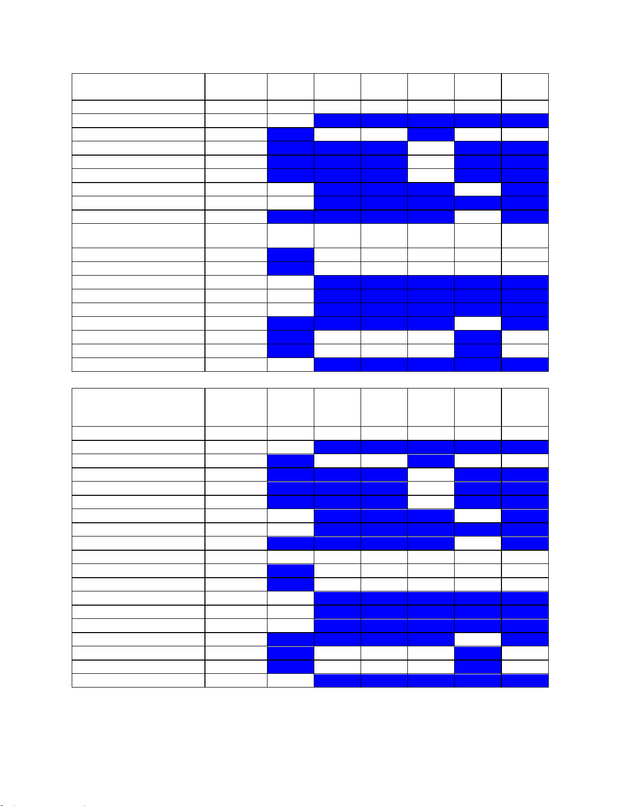
Instructions for Use
C10-3 CDT
MI
TIS Scan
TIS nonscan < 1
TIS nonscan > 1
TIB non-
scan
TIC
1.52
0.74 - -
1.14
0.79
Pr,a
[Mpa]
3.03
P
[mW]
27.89 -
16.22
27.89
min of[Pa(Zs),Ita,a(Zs)
[mW] -
Zs
[cm] -
Zbp
[cm] -
Zb
[cm]
1.83 2.17
z at max Ipi,a
[cm]
1.83
deq(Zb)
[cm]
0.19
fawf
[cm]
3.96
3.96-
6.06 - -
3.63
3.96-
6.06
Dim of Aaprt X
[cm] 0.77 - -
1.01
0.77
Dim of Aaprt Y
[cm] 0.60 - -
0.60
0.60
TD
[usec]
0.40
PRR
[Hz]
420
Pr at max Ipi
[Mpa]
3.76
deq at max Ipi
[cm]
0.17
FLx
[cm] 5.00 - - 5.00
FLy
[cm] 3.50 - - 3.50
Ipa,a at max MI
[W/cm2]
576.4
C10-3 ocular B
mode
MI
TIS Scan
TIS nonscan < 1
TIS nonscan > 1
TIB non-
scan
TIC
0.14
0.01 - - - 0.01
Pr,a
[Mpa]
0.37
P
[mW] 0.38 - - 0.38
min of[Pa(Zs),Ita,a(Zs)
[mW] -
Zs
[cm] -
Zbp
[cm] -
Zb
[cm]
1.67 -
z at max Ipi,a
[cm]
1.67
deq(Zb)
[cm] -
fawf
[cm]
6.58
6.58 - - - 6.58
Dim of Aaprt X
[cm] 0.38 - - - 0.38
Dim of Aaprt Y
[cm] 0.60 - - - 0.60
TD
[usec]
0.28
PRR
[Hz]
5192
Pr at max Ipi
[Mpa]
0.54
deq at max Ipi
[cm] -
FLx
[cm] 2.00 - - 2.00
FLy
[cm] 3.50 - - 3.50
Ipa,a at max MI
[W/cm2]
4.0
z.one
pro
Instructions for Use, Q00350-00, Rev D 100 | P a g e
 Loading...