

Page 1
Page 2

REVISION HISTORY
REV DESCRIPTION DATE
A Initial Release to support Version 4.0 Software/Hardware 1/09
B Updated software release and Scan Module support 4/09
C Updated to 4.1/4.2 software releases 9/09
D Updated Release to Support 4.7 SW & Product Changes 7/11
Q00169 Rev D Page 2 of 304
"Note: Copies are uncontrolled documents - For revision verification see the Master Docum e ntation List"
Page 3

TABLE OF CONTENTS
1 INTRODUCTION.........................................................................................................................................10
1.1 Purpose.................................................................................................................................................11
1.2 Product Overview ................................................................................................................................11
1.3 Product Features.................................................................................................................................12
1.4 Definitions/Acronyms ..........................................................................................................................13
1.5 Documentation Conventions..............................................................................................................15
2 SAFETY .......................................................................................................................................................17
2.1 CAUTIONs and WARNINGs During Service/Operation................................................................17
2.2 Battery WARNINGs.............................................................................................................................18
2.3 CAUTIONs During Service.................................................................................................................18
2.4 Battery CAUTIONs..............................................................................................................................19
2.5 USB Memory Stick CAUTIONs .........................................................................................................19
2.6 Networking CAUTION.........................................................................................................................19
3 SYSTEM SPECIFICATIONS ....................................................................................................................20
3.1 System Dimensions................................................................................................................................20
3.2 Displays.................................................................................................................................................21
3.3 Image Archive or Export Storage......................................................................................................22
3.4 Transducers..........................................................................................................................................22
3.5 Accessories/Options...............................................................................................................................26
3.6 Peripherals............................................................................................................................................26
3.7 Site Requirements...............................................................................................................................26
3.8 System Power......................................................................................................................................27
3.9 System Power Protection...................................................................................................................27
3.10 Electrical Specifications..................................................................................................................27
3.11 Temperature, Humidity, Pressure Limits......................................................................................29
3.12 Device Classification .......................................................................................................................30
3.13 Safety Standards..............................................................................................................................30
3.14 DICOM Standard..............................................................................................................................30
3.15 Product Labeling..............................................................................................................................30
4 TOP-LEVEL PRODUCT OVERVIEW......................................................................................................35
4.1 Major Assembly Identification............................................................................................................35
4.2 Transducers..........................................................................................................................................35
Q00169 Rev D Page 3 of 304
"Note: Copies are uncontrolled documents - For revision verification see the Master Docum e ntation List"
Page 4

4.3 Accessory Components......................................................................................................................36
4.4 SmartCart Major Assemblies (shown with MTP Multi- probe Option).........................................37
4.5 miniCart Major Assemblies ................................................................................................................38
4.6 SmartCart User Interface Controls (Overview)...............................................................................39
4.7 Scan Engine User Interface Controls (Overview)...........................................................................41
4.8 SmartCart User Interface Controls (Detailed) – Version 1............................................................42
4.9 SmartCart User Interface Controls (Detailed) – “Enhanced” Version (2)....................................47
4.10 SmartCart & miniCart Keyboard Controls (Detailed)..................................................................52
4.11 Scan Engine User Interface Controls (Detailed).........................................................................55
4.12 SmartCart Rear I/O Panel: Layout & Functional Definitions ....................................................58
4.13 miniCart I/O Connections: Layout & Functional Definitions .....................................................58
4.14 Scan Engine/Scan Module Rear I/O Ports: Layout & Functional Definitions ........................59
4.15 AVED: Audio-Video Extension Device - I/O Panel: (Option)...................................................59
5 SYSTEM UNCRATING & INSTALLATION PROCEDURES ..............................................................61
5.1 Product Shipment................................................................................................................................61
5.2 Electrical Requirements......................................................................................................................61
5.3 Environmental and Space Requirements........................................................................................61
5.4 Uncrating...............................................................................................................................................61
5.5 Mechanical Verification.......................................................................................................................65
5.6 System Installation:.............................................................................................................................65
5.7 Transporting - Shipping the Scan Engine/Scan Module................................................................74
6 BASIC SYSTEM CONFIGURATION.......................................................................................................75
6.1 Basic System Configuration Procedures .........................................................................................75
7 ARCHIVE MENU FUNCTIONS................................................................................................................83
7.1 “Media” & “Store/Print” Button Configuration...................................................................................83
7.2 “Exam Export” Menu ...........................................................................................................................86
7.3 “Exam Management” Menu................................................................................................................87
7.4 Archive “Export” – OPTION menu.....................................................................................................93
7.5 “Serial Port” Setup - (Export Calc Report Data)..............................................................................95
8 DICOM CONFIGURATION.......................................................................................................................98
8.1 “DICOM” Configuration Overview .....................................................................................................98
8.2 “DICOM” Configuration Parameter Definitions:...............................................................................99
8.3 Z.ONEUltra Pre-Install Survey Form (Sample Only)....................................................................102
Q00169 Rev D Page 4 of 304
"Note: Copies are uncontrolled documents - For revision verification see the Master Docum e ntation List"
Page 5

8.4 “DICOM” Configuration Procedure - Menus..................................................................................106
8.5 “Network” Setup.................................................................................................................................114
8.6 “FTP” Setup........................................................................................................................................116
9 ADVANCED SYSTEM SETUP CONFIGURATION............................................................................118
9.1 “Security” Setup Menus....................................................................................................................118
9.2 “Power Save” Setup Menu...............................................................................................................120
10 GENERAL PROCEDURES................................................................................................................122
10.1 Installing USB Memory Stick, into the Scan Engine/Scan Module.........................................122
11 FUNCTIONAL DESCRIPTIONS.........................................................................................................123
11.1 Overall System...............................................................................................................................123
11.2 SmartCart........................................................................................................................................125
12 POWER & SIGNAL DISTRIBUTION DIAGRAMS..........................................................................129
12.1 SmartCart Power Module Block Diagram (Basic).....................................................................130
12.2 SmartCart Power Module Block Diagram (Detailed)................................................................131
12.3 SmartCart Main Board Cable Connect Diagram (Original DVD Config) ...............................132
12.4 SmartCart Main Board Cable Connect Diagram (IDE/SATA Adapter DVD Config)............133
12.5 SmartCart Main Board Cable Connection Diagram (USB Style DVD Configuration) .........134
12.6 miniCart AC/DC Power Distribution Diagram ............................................................................135
13 FUNCTIONAL BLOCK DIAGRAMS..................................................................................................136
13.1 Z.ONEUltra Overall System Block Diagram (SmartCart w/Cardiac-Option Configuration) 137
13.2 miniCart Configuration: Overall System Block Diagram.............................................................138
13.3 Z.ONEUltra SmartCart - Cardiac Module (CW/ECG) Option - Block Diagram....................139
14 ASSEMBLY DIAGRAMS.....................................................................................................................140
14.1 SmartCart: Power Module Functional Identification .................................................................140
15 PERIPHERALS & ACCESSORIES...................................................................................................141
15.1 DVD/CD Burner - (Internal)"........................................................................................................141
15.2 AVED – Audio Video Extension Device Box - (Option)"..........................................................142
15.3 SONY UP-D897 USB Digital Printer...........................................................................................148
15.4 SONY UP-D25MD Color Printer..................................................................................................154
15.5 HP LaserJet Network (REPORT) Printer ...................................................................................156
15.6 2- Pedal Footswitch.......................................................................................................................160
16 SOFTWARE PROCEDURES..............................................................................................................161
Q00169 Rev D Page 5 of 304
"Note: Copies are uncontrolled documents - For revision verification see the Master Docum e ntation List"
Page 6

16.1 SCAN ENGINE: Standard Software Installation/Upgrade Procedure....................................161
16.2 SCAN ENGINE (Only) “Advanced” Software Installation Procedure.....................................163
16.3 SCAN MODULE: Standard Software Installation/Upgrade Procedure..................................167
16.4 SCAN MODULE: “Clean” Software Install Procedure (“SERVICE” key)..............................169
16.5 SCAN MODULE: “Clean” Software Install Procedure (Undocked or Auto-Load)...............170
16.6 FTP Site Access: Software/File Downloads from Zonare .....................................................172
16.7 “DIAGNOSTIC” Panel Operations...............................................................................................172
17 CLEANING AND DISINFECTING PROCEDURES.........................................................................183
17.1 SmartCart........................................................................................................................................183
17.2 Scan Engine....................................................................................................................................184
17.3 Transducers....................................................................................................................................185
18 MAINTENANCE – CALIBRATION PROCEDURES.......................................................................189
18.1 Foreword .........................................................................................................................................189
18.2 List: Maintenance Procedures......................................................................................................189
18.3 List: Calibration Procedures.........................................................................................................189
18.4 PIC Reset (Power Supply) Procedure.......................................................................................190
18.5 Z-PAK “RECONDITION” Procedure - (SmartCart)...................................................................190
18.6 UI Lift (Gas spring) Release Cable Adjustment - (SmartCart)................................................192
18.7 Touchscreen Calibration - (Scan Engine)..................................................................................193
18.8 Display Monitor Adjustment – User Settings .............................................................................195
19 SYSTEM TROUBLESHOOTING........................................................................................................197
19.1 Foreword .........................................................................................................................................197
19.2 Technical Support Contact Information......................................................................................197
19.3 Troubleshooting..............................................................................................................................199
19.4 System Status LED & Error Code Definitions............................................................................206
19.5 Scan Engine Fan Operation.........................................................................................................214
19.6 SmartCart LCD Display Troubleshooting...................................................................................214
19.7 Battery Performance – Charge Times - Reconditioning ..........................................................215
20 REPAIR PROCEDURES .....................................................................................................................217
20.1 Foreword .........................................................................................................................................217
20.2 Recommended Tools ....................................................................................................................217
20.3 Hardware Service/Replacement Procedures (SmartCart).......................................................217
20.4 Hardware Service/Replacement Procedures (miniCart)..........................................................277
Q00169 Rev D Page 6 of 304
"Note: Copies are uncontrolled documents - For revision verification see the Master Docum e ntation List"
Page 7

20.5 Hardware Service/Replacement Procedures (Scan Engine)..................................................287
20.6 Hardware Service/Replacement Procedures (Transducers)...................................................288
20.7 Service Software Procedures.......................................................................................................291
21 PART NUMBER INFORMATION.......................................................................................................293
21.1 SmartCart........................................................................................................................................293
21.2 miniCart ...........................................................................................................................................296
21.3 Scan Engine....................................................................................................................................298
21.4 Scan Module...................................................................................................................................299
21.5 Transducers....................................................................................................................................300
21.6 Peripherals......................................................................................................................................302
22 INDEX .....................................................................................................................................................303
Q00169 Rev D Page 7 of 304
"Note: Copies are uncontrolled documents - For revision verification see the Master Docum e ntation List"
Page 8

TABLE OF FIGURES
FIGURE 1: LABEL, SCAN ENGINE – SERIAL/PART NO..........................................................................................................31
FIGURE 2: LABEL, SCAN MODULE – SERIAL/PART NO........................................................................................................31
FIGURE 3: LABEL, SCAN ENGINE BATTERY (VERSION 1) - SERIAL/PART NO.....................................................................31
FIGURE 4: LABEL, SCAN ENGINE BATTERY (VERSION 2) - SERIAL/PART NO.....................................................................31
FIGURE 5: LABEL, 100V-240V SMARTCART REAR PANEL - SERIAL/PART NO..................................................................32
FIGURE 6: LABEL, SMARTCART Z-PAK BATTERY ................................................................................................................32
FIGURE 7: LABEL, MINICART REAR PANEL - SERIAL/PART NO.............................................................................................32
FIGURE 8: LABEL, LINEAR ARRAY TRANSDUCERS - SERIAL/PART NO................................................................................33
FIGURE 9: LABEL, CURVED ARRAY TRANSDUCERS - SERIAL/PART NO..............................................................................33
FIGURE 10: LABEL, ENDO CAVITY TRANSDUCER - SERIAL/PART NO.................................................................................33
FIGURE 11: LABEL, PHASED TRANSDUCERS - SERIAL/PART NO........................................................................................33
FIGURE 12: LABEL, SPECIALTY TRANSDUCERS - SERIAL/PART NO....................................................................................33
FIGURE 13: LABEL, AC POWER BATTERY ADAPTER...........................................................................................................34
FIGURE 14: LABEL, AC POWER ADAPTER POWER SUPPLY................................................................................................34
FIGURE 15: Z.ONEULTRA MAJOR ASSEMBLY ILLUSTRATIONS............................................................................................ 35
FIGURE 16: TRANSDUCER ILLUSTRATIONS .......................................................................................................................... 35
FIGURE 17: ACCESSORIES ...................................................................................................................................................36
FIGURE 18: SMARTCART KEYBOARD CONTROLS (OVERVIEW)...........................................................................................39
FIGURE 19: SMARTCART USER INTERFACE (VERSION 1) CONTROLS (OVERVIEW)...........................................................39
FIGURE 20: SMARTCART USER INTERFACE (“ENHANCED” VERSION) CONTROLS (OVERVIEW).........................................40
FIGURE 21: SCAN ENGINE USER INTERFACE CONTROLS (OVERVIEW)............................................................................... 41
FIGURE 22: SMARTCART USER INTERFACE LAYOUT – VERSION 1......................................................................................42
FIGURE 23: SMARTCART USER INTERFACE LAYOUT – “ENHANCED” VERSION (2).............................................................47
FIGURE 24: SMARTCART KEYBOARD LAYOUT......................................................................................................................52
FIGURE 25: MINICART KEYBOARD LAYOUT........................................................................................................................... 52
FIGURE 26: SCAN ENGINE USER INTERFACE LAYOUT (DETAILED).....................................................................................55
FIGURE 27: SMARTCART REAR I/O PANEL..........................................................................................................................58
FIGURE 28: MINICART USB HUB CONNECTIONS.................................................................................................................58
FIGURE 29: SCAN ENGINE/SCAN MODULE REAR I/O CONNECTIONS.................................................................................59
FIGURE 30: AVED OPTION - I/O PANEL (SMARTCART)...................................................................................................... 59
FIGURE 31: MAIN SHIPPING CONTAINER REMOVAL ..............................................................................................................62
FIGURE 32: LOADING RAMP LOWERING................................................................................................................................62
FIGURE 33: REMOVABLE SECTION OF SHIPPING BASE......................................................................................................... 62
FIGURE 34: REMOVING PROTECTIVE STORAGE BAG............................................................................................................ 63
FIGURE 35: BRAKE RELEASE OF WHEELS.............................................................................................................................63
FIGURE 36: BATTERY PACK INSTALLATION..........................................................................................................................66
FIGURE 37: SCANNER DOCKING IN SMARTCART.................................................................................................................66
FIGURE 38: SCAN ENGINE TO MINICART DOCKING..............................................................................................................67
FIGURE 39: AC POWER ADAPTER .......................................................................................................................................70
FIGURE 40: 2-BAY BATTERY CHARGER...............................................................................................................................72
FIGURE 41: INSTALLING USB MEMORY STICK...................................................................................................................122
FIGURE 42: SMARTCART: BRAKE MECHANISM..................................................................................................................127
FIGURE 43: SMARTCART: HEIGHT ADJUSTMENT MECHANISM.......................................................................................... 128
FIGURE 44: SMARTCART: POWER MODULE BLOCK DIAGRAM (BASIC)............................................................................ 130
FIGURE 45: SMARTCART: POWER MODULE BLOCK DIAGRAM (DETAILED) .....................................................................131
FIGURE 46: SMARTCART: MAIN BOARD CABLE CONNECTION DIAGRAMS (ORIGINAL DVD)...........................................132
FIGURE 47: SMARTCART: MAIN BOARD CABLE CONNECTION DIAGRAMS (IDE/USB ADAPTER STYLE DVD)............... 133
FIGURE 48: SMARTCART: MAIN BOARD CABLE CONNECTION DIAGRAMS (USB STYLE DVD DRIVE)............................134
FIGURE 49: MINICART: AC/DC POWER DISTRIBUTION DIAGRAM.....................................................................................135
FIGURE 50: OVERALL SYSTEM BLOCK DIAGRAM (ADVHDWE SCAN ENGINE & SMARTCART W/CARDIAC OPTION) .......137
FIGURE 51: OVERALL SYSTEM BLOCK DIAGRAM (ADVHDWE SCAN ENGINE & MINICART)..............................................138
FIGURE 52: SMARTCART: CARDIAC OPTION (CW/ECG) MODULE BLOCK DIAGRAM.......................................................139
Q00169 Rev D Page 8 of 304
"Note: Copies are uncontrolled documents - For revision verification see the Master Docum e ntation List"
Page 9

FIGURE 53: SMARTCART: POWER MODULE FUNCTIONS DIAGRAM ..................................................................................140
FIGURE 54: AVED: AUDIO VIDEO EXTENSION DEVICE I/O PANEL DIAGRAM...................................................................144
FIGURE 55: MENU SETTINGS (UP-D897)..........................................................................................................................150
FIGURE 56: OPERATOR CONTROLS (UP-D897) ............................................................................................................... 152
FIGURE 57: APPROVED DISINFECTANTS TABLE (IMMERSION-METHOD)...........................................................................185
FIGURE 58: APPROVED DISINFECTANTS TABLE (WIPE-METHOD).................................................................................... 186
FIGURE 59: TRANSDUCER IMMERSION LIMITS....................................................................................................................187
FIGURE 60: MINICART 13” DISPLAY: RECOMMENDED SETTINGS -....................................................................................195
FIGURE 61: SMARTCART 19” DISPLAY: RECOMMENDED SETTINGS................................................................................. 195
FIGURE 62: TRANSDUCER CONNECTOR PIN DAMAGE – (EXAMPLE)................................................................................199
Q00169 Rev D Page 9 of 304
"Note: Copies are uncontrolled documents - For revision verification see the Master Docum e ntation List"
Page 10

1 INTRODUCTION
USA, Canada, Asia
ZONARE Medical Systems, Inc.
420 N. Bernardo
Mountain View, CA 94043
Toll-free line (in USA only) live-voice support: ................................................. 1-877-913-9663
Standard line (USA & International) live-voice support: ................................... 1-650-316-3199
Tech Support fax line ........................................................................................... 1-650-230-2817
Customer Support E-Mail: .......................techsupport@zonare.com or salessupport@zonare.com
Web site..................................................www.zonare.com
FTP site (Service) ..................................ftp://12.40.200.87
Toll-free live-phone support: ............. 1-877-913-9663 (5:00AM – 5:00PM, Pacific Standard Time)
Tech Support FAX line ...................... 1-650-230-2817
Tech Support e-mail........................... techsupport@zonare.com
Corporate web site.............................. www.zonare.com
FTP site (Tech Support Window):
URL............................................ftp://12.40.200.87
Enter the following User Name and Password information:
User Name: (call Tech Support for current login information)
Password: (call Tech Support for current login information)
Q00169 Rev D Page 10 of 304
"Note: Copies are uncontrolled documents - For revision verification see the Master Docum e ntation List"
Page 11

Europe
ZONARE Medical Systems GmbH
Henkestrasse 91
91052 Erlangen, Germany
Tech Support Phone .......................... (+49) 9131-974 94-0 (8:00AM – 5:00PM)
Tech Support e-mail........................... info@zonare.de
Corporate web site.............................. www.zonare.com
1.1 Purpose
This manual’s purpose is to provide information to assist service personnel in performing the service,
maintenance, and repair procedures that may be required to support ZONARE’s Z.ONEUltra
Diagnostic Ultrasound System product.
1.2 Product Overview
ZONARE’s Z.ONEUltra Convertible Ultrasound System provides a combination of a full-featured,
cart-based ultrasound system, with the versatility of a compact, easily transportable to the patient, selfcontained portable unit.
The Z.ONEUltra Convertible Ultrasound System is offered in two different models, utilizing two
different configurations of Carts. The sub-systems that comprise the Z.ONEUltra product are listed
below:
Full-Feature SmartCart or
Portable “Scan Engine” (or docked “Scan Module”
Ultrasound transducer(s)
The portable Scan Engine consists of a limited number of field replaceable units (FRU’s). The FRU’s
for this unit are:
Lithium-Ion battery pack
USB Memory Stick
Scan Engine (complete)
lightweight miniCart
The SmartCart consists of a limited number of field replaceable units (FRU’s). The FRU’s for this
unit are:
Q00169 Rev D Page 11 of 304
"Note: Copies are uncontrolled documents - For revision verification see the Master Docum e ntation List"
Page 12

19” Display Monitor
User Interface Assembly
OLED Sub-Assembly (part of UI)
Main Board Assembly
Power Supply Module
Z-PAK Battery Pack
Scanner Deck (w/MTP)
MTP Bolster Plate (or MTP w/CW)
ECG Module
Misc cables and mechanical assemblies
The miniCart consists of a limited number of field replaceable units (FRU’s). The FRU’s for this unit
are:
AC Fuses
Main Power Supply (DC)
USB Hub
LCD Display
Remote Keyboard
Wheels
In addition to the two different Cart offerings, the Z.ONEUltra Ultrasound System is offered with two
different configurations of scanner electronics.
One version being a standalone portable use “Scan Engine” (with local LCD display and user
interface controls), and the other being a “brains only” (non-portable) “Scan Module”.
Scan Engine Scan Module
The ultrasound transducers are replaced as a single FRU, with no field-serviceable parts.
1.3 Product Features
The Z.ONEUltra ultrasound system includes the following key features:
Q00169 Rev D Page 12 of 304
"Note: Copies are uncontrolled documents - For revision verification see the Master Docum e ntation List"
Page 13

Full function scanning modalities (B-Scan, M-Mode, Color Flow, Power Doppler, PW Dopper)
Remote portability for patient scanning
1.4 Definitions/Acronyms
2D: ................. Two dimensional (B-Mode, Color mode)
BMP: ............. Bit MaP
C: ................... Color Flow Mode (Doppler)
D:................... Doppler (Pulsed Wave) Mode
DICOM:........ Digital Imaging and COmmunication in Medicine
DSP:............... Digital Signal Processing
ESD:............... Electro Static Discharge
EV:................. Endo Vaginal
FPGA: ........... Field Programmable Gate Array
FRU:.............. Field Replaceable Unit
HSSL:............ High Speed Serial Link
LCD:.............. Liquid Crystal Display
LED:.............. Light Emitting Diode
M:................... M-Mode (Motion Mode - Tissue)
NTSC:............
National Television Standards Committee (video standard)
PAL: .............. Phase Alternation by Line (video standard)
PRF:............... Pulse Repetition Frequency
PW:................ Pulsed Wave Mode (Doppler)
Retrospective:.. Post-processing performed on frozen images from memory
SVGA: ........... Super Video Graphics Array
DGC: ............. Depth Gain Compensation
USB:............... Universal Serial Bus
Q00169 Rev D Page 13 of 304
"Note: Copies are uncontrolled documents - For revision verification see the Master Docum e ntation List"
Page 14

VKB:.............. Virtual KeyBoard
Q00169 Rev D Page 14 of 304
"Note: Copies are uncontrolled documents - For revision verification see the Master Docum e ntation List"
Page 15

1.5 Documentation Conventions
This following alert conventions are used in this manual:
1.5.1 Alert Messages
1. A WARNING indicates that PERSONAL INJURY OR DEATH may occur to patient and/or
user if the user does not observe the provided information.
WARNING
2. A CAUTION indicates that DAMAGE TO EQUIPMENT may occur if the user does not
observe the provided information.
CAUTION
3. A PRECAUTION indicates that INCONVENIENCE TO THE USER (such as loss of text
entries or saved settings) may result if the user does not observe the provided information.
PRECAUTION
4. Common terms that have a special meaning for the Z.ONEUltra (e.g. Menu Control or
Trackball) are capitalized to distinguish their special usage (as opposed to a person who does
navigation).
5. Control and function names (e.g. Print Button, Image Display) are capitalized for recognition.
6. Items to be acted upon are underlined (e.g. press the Store Button
). Items needing emphasis
are in boldface type.
1.5.2 Symbols
The following symbol conventions are used in this manual, and/or on the Z.ONEUltra product:
This symbol is used to draw attention to information that may relate to safety of the
patient, the operator, or the equipment.
Q00169 Rev D Page 15 of 304
"Note: Copies are uncontrolled documents - For revision verification see the Master Docum e ntation List"
Page 16

Caution: ESD sensitive
This symbol indicates that the equipment is not Category AP, and therefore must not
be used in the presence of flammable liquids or gasses.
.
Type BF patient applied part (B= body, F= floating applied part).
This symbol indicates that the equipment does not utilize a floating double insulated
isolation connection, and therefore must not be connected to external equipment that
is not protectively earthed (DO NOT connect to class II equipment).
Storage/Operating Temperature conditions
Alternating Current (AC)
Direct Current (DC)
Date of manufacture
Q00169 Rev D Page 16 of 304
"Note: Copies are uncontrolled documents - For revision verification see the Master Docum e ntation List"
Page 17
2 SAFETY
It is extremely important to read the following definitions of WARNING information, prior to
beginning any service on any sub-system within the Z.ONEUltra product. As you see applicability
of each of these noted WARNINGs, during the course of the servicing process, be prepared to
avoid harm to persons and equipment by proper adherence.
2.1 CAUTIONs and WARNINGs During Service/Operation
CAUTION
On the miniCart, to prevent possible damage to the 13” display monitor during system
transport (or moving for relocation within the facility) the monitor should first be folded down
to horizontal, rotated to a center position, and “locked” into place using the provided retaining
pin located on the bottom of the display arm.
CAUTION
To prevent possible damage to the electronics of the system from condensation, the following
warning must be observed:
Anytime that any Zonare equipment (Scan Engine, SmartCart or minCart) is being moved from
an environment that differs greatly in temperature and/or humidity, from the environment
where it has been moved for intended operation, (as a result of shipping or transport) the unit
should be allowed to stand for a period of no less than 30 minutes
powering on.
, prior to inserting battery or
WARNING
WARNING
WARNING
Inspect all cables and power cords BEFORE powering-on the Z.ONEUltra system; or
connecting the transducer. Do not use the system if visual signs of external damage are
observed.
To achieve proper grounding reliability, the Z.ONEUltra SmartCart or miniCart power plug
must be fully inserted into a receptacle marked 'Hospital Grade". Do not remove the
grounding wire. If there is any question of power outlet or power cord integrity, do not
proceed. Obtain qualified technical assistance
.
The ZONARE Z.ONEUltra contains no operator-serviceable components within the enclosures.
To avoid electrical shock, the no covers should be removed except by ZONARE factory trained
personnel. Failure to do so may void the system warranty or service contract coverage
Warnings.
Q00169 Rev D Page 17 of 304
"Note: Copies are uncontrolled documents - For revision verification see the Master Docum e ntation List"
Page 18
WARNING
Do not operate the Z.ONEUltra system in the presence of flammable anesthetics or in a room
recently washed with flammable cleaning and disinfecting agents. Cleaners can produce
explosive vapors. Check labels of original containers of cleaners and disinfectants for warnings
about vapors. Thoroughly ventilate the room, if such vapors may potentially be present, prior
to activating any of the
Z.ONEUltra components.
2.2 Battery WARNINGs
WARNINGS.
The battery has a safe smart device. Do not disassemble or alter the battery in any
way.
Charge the battery at room temperature.
Do not short-circuit battery by directly connecting the positive and negative terminals
with metal objects.
Do not heat or discard battery in a fire.
Do not expose the battery to temperatures above 150 degree F.
Do not charge the battery near a heat source
Do not leave battery in direct sunlight
Recharge battery only using Scan Engine in a docked condition in Z.ONEUltra
SuperCar or miniCartt, or remotely using ZONARE Z.ONE battery charger.
Do not use a damaged battery.
Inspect the battery for damage before charging or placing the battery in the
Z.ONEUltra.
Do not connect battery to an electrical power outlet.
Do not continue to recharge the battery if it does not recharge fully after 4 hours
Battery MUST be REMOVED from Scan Engine, during shipping/transport of the
Z.ONEUltra
2.3 CAUTIONs During Service
CAUTIONS
Apply proper line voltage. Verify that the Z.ONEUltra system is compatible to match
the AC voltage of site receptacle. Also verify that all plugs match the receptacle type.
Mismatched voltage or plug configuration can damage system components.
Protect the system from water or other liquids that could drip into the electronic
components.
Do not drop the transducer(s), or allow them to impact any hard surfaces.
Q00169 Rev D Page 18 of 304
"Note: Copies are uncontrolled documents - For revision verification see the Master Docum e ntation List"
Page 19
Avoid allowing metal contact pins on connector-end of transducers to come in
contact with foreign surfaces (potential for bending pins).
Perform no unauthorized modification to any of the Z.ONEUltra sub-systems.
Unauthorized modification can introduce additional hazards to the product.
2.4 Battery CAUTIONs
CAUTIONS
To protect the battery from potential thermal damage, the system monitors the
temperature of the battery at all times. If the battery is detected as exceeding the
maximum safe operating temperature, a warning message will appear on the display of
the Z.ONEUltra.
To prevent possible damage to the unit, the battery should be REMOVED from the
Scan Engine prior to transport or shipment.
Do not immerse battery in water or allow it to get wet.
Do not put the battery into a microwave oven or pressurized container.
Use only batteries provided by ZONARE
Store the battery between -20 to 60o Celsius (-4 o to 158
o
F).
If the battery leaks, emits orders, emits heat, is deformed or discolored in any way
immediately remove it and stop using it.
2.5 USB Memory Stick CAUTIONs
CAUTIONS
USB Memory Sticks that are purchased from outside sources (besides Zonare) may not be
compatible for use in the Z.ONEUltra. USB Memory Sticks which are labeled as “U3
Smart Technology” on their label or packaging, will NOT be recognized (or function) in
the Z.ONEUltra.
In the case of having one of these incompatible format USB Memory Sticks. There are
freeware U3 Smart Technology “Removal” programs available on the internet, that can
be downloaded and run to make the USB Memory Sticks useable on the Z.ONEUltra
2.6 Networking CAUTION
CAUTIONS
In order to comply with Electro-Magnetic Compliance it is necessary that the
Z.ONEUltra be connected to available Ethernet resources using a high quality, shielded
CAT-5 cable.
Q00169 Rev D Page 19 of 304
"Note: Copies are uncontrolled documents - For revision verification see the Master Docum e ntation List"
Page 20

3 SYSTEM SPECIFICATIONS
This section contains Z.ONEUltra system and accessory specifications. For information on the
specifications for ZONARE authorized peripherals, refer to the manufacturers’ documentation.
3.1 System Dimensions
SmartCart (with Scan Engine installed)
Height:
- Max operational: 157.5 cm (62 in)
- Min operational: 128 cm (50.5 in)
- Display lowered for transport: 104 cm (41 in)
Width: 51 cm (20.1 in)
Depth: 72 cm (28.2 in)
Weight: 57 kg (125lb.)
miniCart (with Scan Engine installed)
Height:
- Max operational: 160 cm (63 in)
- Min operational: 134 cm (53 in)
- Display lowered for transport: 104 cm (41.5 in.)
Width: 57.2 cm (22.5 in)
Depth: 56.1 cm (22.0 in)
Weight: 55 kg (132 lbs.)
Scan Engine
Height: 7.3 cm (2.9 in)
Width: 18.7 cm (7.4 in)
Depth: 25 cm (9.8 in)
Weight: 2.5 kg (5.6 lb) – with battery, no probe
Scan Module
Height: 5.3 cm (2.1 in)
Width: 22.3 cm (8.8 in)
Depth: 25 cm (10.0 in)
Weight: 1.6 kg (3.5 lb)
Q00169 Rev D Page 20 of 304
"Note: Copies are uncontrolled documents - For revision verification see the Master Docum e ntation List"
Page 21

3.2 Displays
SmartCart
19” high resolution color LCD display
1280 x 1024 display format (internal)
1280 x 1024 / 800 x 600 video format - configurable (HDMI output)
0.41 mm pixel pitch
Viewing angle (H/V): 170 degrees typical
Minimum 10:1 contrast
+/- 90o rotation
30o backward tilt
Full 90o forward tilt into secure transport position
Advanced setup parameters via on-screen menu
Integrated system programmed video settings
Multi-Transducer Port (3 Connectors) - Option
miniCart
13” high resolution color LCD display
640x480 display format (internal)
0.41 mm pixel pitch
Viewing angle (H/V): 170 degrees typical
Minimum 10:1 contrast
+/- 90o rotation
30o backward tilt
Full 90o forward tilt into secure transport position
Integrated system programmed video settings
Scan Engine
5.8” high resolution color LCD display
800x480 display format (internal)
640x480 video format (HDMI output port)
0.16 mm pitch
Manual Brightness and Contrast controls
USB 2.0 I/O port (one)
DC power (+12V) input port
Scan Module
640x480 video format (HDMI port)
USB 2.0 port (one)
Q00169 Rev D Page 21 of 304
"Note: Copies are uncontrolled documents - For revision verification see the Master Docum e ntation List"
Page 22

DC power (+12V) input port
3.3 Image Archive or Export Storage
Scan Engine - Internal:
IMPORTANT
The image storage capacity numbers listed below apply ONLY to standalone
(undocked) Scan Engine use, or use when docked in a miniCart. In these applications
resolution of the individual image is 640 x 480.
The image storage capactiy numbers, when a Scan Engine is being used while docked
in a SmartCart, will be approximately 1/3 less. This is due to the higher image
resolution of 800 x 600 that is used in the Z.ONEUltra application.
- 512MB Internal CompactFlash Storage (Standard)
DICOM uncompressed: 1280 images
DICOM RLE: 4060 images
BMP: 1700 images
- 2GB Internal CompactFlash Storage (Option)
DICOM uncompressed: 5000 images
DICOM RLE: 15,900 images
BMP: 6650 images
SmartCart - Internal:
- Internal Hard Drive (120GB version specs referenced below)
DICOM uncompressed: 300,000 images
DICOM RLE: 944,000 images
BMP: 399,0000 images
- Slimline Internal DVD+RW / CD-RW Drive
Cart S/N 3xxx and below:
ATAPI (Parallel) Interface
24X speed writing for CD-R, DVD+R, or DVD+RW discs
Cart S/N 4xxx and above:
USB (Serial) Interface
24X speed writing for CD-R, DVD+R, or DVD+RW discs
3.4 Transducers
C10-3 ........................................................ (I.D. 3)
Penetration Depth 13 CM
Q00169 Rev D Page 22 of 304
"Note: Copies are uncontrolled documents - For revision verification see the Master Docum e ntation List"
Page 23

Number of Elements 64
Field of View 80 degrees
Radius of Curvature 16 mm
Ultrasound Bandwidth 10-3 MHz
C9-4T Convex ...........................................(I.D. 146)
Penetration Depth 14 CM
Number of Elements 128
Field of View 135 degrees
Radius of Curvature 11.5 mm
Ultrasound Bandwidth 9-4 MHz
C9-3 Convex..............................................(I.D. 130)
Penetration Depth 18 CM
Number of Elements 128
Field of View 67 degrees
Radius of Curvature 33 mm
Ultrasound Bandwidth 9-3 MHz
C8-33D 3-D .............................................. (I.D. 140)
Penetration Depth 24 CM
Number of Elements 128
Field of View 79 degrees
Radius of Curvature 40 mm
Ultrasound Bandwidth 8-3 MHz
C6-2 Convex..............................................(I.D. 129)
Penetration Depth 24 CM
Number of Elements 128
Field of View 65 degrees
Radius of Curvature 50 mm
Ultrasound Bandwidth 6-2 MHz
C5-2 Convex
............................................ (I.D. 128)
Penetration Depth 24 CM
Number of Elements 128
Field of View 65 degrees
Radius of Curvature 50 mm
Ultrasound Bandwidth 4-1 MHz
C4-1 Convex
Q00169 Rev D Page 23 of 304
..............................................(I.D. 2)
"Note: Copies are uncontrolled documents - For revision verification see the Master Docum e ntation List"
Page 24

Penetration Depth 30 CM
Number of Elements 64
Field of View 80 degrees
Ultrasound Bandwidth 4-1 MHz
L14-5sp Linear........................................ (I.D. 70)
Penetration Depth 6 CM
Number of Elements 128
Field of View 26 mm
Ultrasound Bandwidth 14-5 MHz
L14-5W Wide Aperture Linear............. (I.D. 66 or 71)
Penetration Depth 10 CM
Number of Elements 192
Field of View 55 mm
Ultrasound Bandwidth 14-5 MHz
L12-4V Veterinary.................................. (I.D. 67)
Penetration Depth 10 CM
Number of Elements 128
Field of View 63 degrees
Ultrasound Bandwidth 12-4 MHz
L10-5 Linear............................................ (I.D. 64)
Penetration Depth 10 CM
Number of Elements 128
Field of View 38 mm
Ultrasound Bandwidth 10-5 MHz
L8-3 Linear
.............................................. (I.D. 65)
Penetration Depth 10 CM
Number of Elements 128
Field of View 38 mm
Ultrasound Bandwidth 8-3 MHz
E9-3 3-D
................................................... (I.D. 141)
Penetration Depth 14 CM
Number of Elements 128
Field of View 135 degrees
Radius of Curvature 10.0 mm
Q00169 Rev D Page 24 of 304
"Note: Copies are uncontrolled documents - For revision verification see the Master Docum e ntation List"
Page 25

Ultrasound Bandwidth 9-3 MHz
EV9-4 Transvaginal................................ (I.D. 144)
Penetration Depth 14 CM
Number of Elements 128
Field of View 135 degrees
Radius of Curvature 12 mm
Ultrasound Bandwidth 9-4 MHz
P10-4 Phased (version 1)........................ (I.D. 7)
Penetration Depth 14 CM
Number of Elements 128
Field of View 80 degrees
Ultrasound Bandwidth 10-4 MHz
P10-4 Phased (version 2)........................ (I.D. 14)
Penetration Depth 12 CM
Number of Elements 128
Field of View 79.6 degrees
Ultrasound Bandwidth 10-4 MHz
P8-3 TEE ...................................................(I.D. 8)
Penetration Depth 18 CM
Number of Elements 64
Ultrasound Bandwidth 7.5-2.7 MHz
P4-1 Phased ............................................ (I.D. 4)
Penetration Depth 30 CM
Number of Elements 128
Field of View 84 degrees
Ultrasound Bandwidth 4-1 MHz
P4-1c Phased
.............................................(I.D. 5 or 6)
Penetration Depth 30 CM
Number of Elements 64
Field of View 84 degrees
Ultrasound Bandwidth 4-1 MHz
A2CW Doppler-Only
(CW Option Required) – I.D. 514)
Q00169 Rev D Page 25 of 304
"Note: Copies are uncontrolled documents - For revision verification see the Master Docum e ntation List"
Page 26

Number of Elements 2
Ultrasound Frequency 2.0 MHz
Ultrasound Bandwidth n/a
A5CW Doppler-Only (CW Option Required) – I.D. 513)
Number of Elements 2
Ultrasound Frequency 5.0 MHz
Ultrasound Bandwidth n/a
3.5 Accessories/Options
2-Pedal Footswitch (Freeze/Store)
2-Bay Battery Charger
AC Power Adapter
USB Memory Stick
AVED (Audio Video Extension Device) Box
o NTSC output:
Horizontal frequency:...........................15.733 KHz
Vertical frequency:...............................59.94 Hz.
o PAL output:
Horizontal frequency:...........................15.625 KHz
Vertical frequency:...............................50.0 Hz.
3.6 Peripherals
SmartCart:
On-Board (Mounted) – Local Image Printing
Sony UP-D897 USB Digital B/W Printer
Off-Board (Un-mounted)
Sony UP-D25MD Color Printer
HP LaserJet (PostScript-3 style) Network Printer -------------------- (Report printing only)
miniCart:
Sony UP-D897 Digital B/W Printer
3.7 Site Requirements
Power
100 – 120VAC, 50-60Hz or 200 – 240VAC, 50-60Hz (Factory Configurable)
Q00169 Rev D Page 26 of 304
"Note: Copies are uncontrolled documents - For revision verification see the Master Docum e ntation List"
Page 27

Environmental
Cooling consistent with 1024 BTU / hour system output (Scan Engine + SmartCart/miniCart)
o
Ambient air temperature of 0
– 35o Celsius (32 o - 95 o F)
Ambient relative humidity of up to 80%, non-condensing
3.8 System Power
SmartCart
- 90 – 120V @ 6A (max)
- 200 – 240V @3A (max)
- Line Frequency: 50 – 60Hz
- 250 W-h - Nickel Metal Hydride (NiMH) battery pack - (Option)
miniCart
- 100 – 120V @ 6A (max)
- 200 – 240V @3A (max)
- Line Frequency: 50 – 60Hz
3.9 System Power Protection
SmartCart
- Re-settable AC circuit breaker
miniCart
- User-replaceable fuses:
T6.3A/250V ..................................................... (100-120V Systems)
T3.15A/250V ................................................... (200-240V Systems)
3.10 Electrical Specifications
DC Voltages:
SmartCart DC Power Supplies
Voltage Purpose Max Current Rating
+12V
+12V
+7 to +14V
VMain Logic Power 12 A
VScanner Power 8 A
VFan Power
variable
Q00169 Rev D Page 27 of 304
"Note: Copies are uncontrolled documents - For revision verification see the Master Docum e ntation List"
Page 28

+12 to +25V
miniCart DC Power Supplies
Voltage Purpose Max Current Rating
+12V
+12V
+5V
Scanner Power Board DC Supplies
Voltage Purpose Total Current
+1.2V
+1.5V
+2.5V
+3.3V
Vfan
+5.0V
V5.0RTC
+12V
HV1
HV2
HV3
VAux Power (Peripherals)
Scan Engine Power 20 A
LCD Display Source Power 6 A
USB Hub Power
DSP Power 2.3 A
Digital FPGA (Digital Board)
Striker (Analog Board)
FPGA busses
ADC’s +1.8V
ADC’s and AFE’s
DDR SDRAM 0.30 A
CPU, FPGA’s, etc. 2.5 A
Cooling fans 0.25A
Power Supply monitoring
Levels shifters, muxes, eeprom.
Local power for PIC, etc. 25 mA
Pulsers 170 mA
Probe Mux Bias Power Transducer dependent
Transmit Power (Tissue) User variable
Transmit Power (Doppler) User variable
Future use
8 A
11.2 A
7.4 A
10 mA
“Z-Pack” Battery (SmartCart) – (Option)
Battery, 13-cell, 15.6 VDC, 16 A-hours, rechargeable Nickel Metal Hydride battery pack
Weight: 7.7 lbs.
Operating range: (values listed are approximations)
- Active use......................................At least 1 hour (mode/display brightness dependent)
- Storage mode.................................Less then 50% loss - 1 month
Battery (Scan Engine)
Battery, 4-cell, 7.4 VDC, 4.4 amp-hours, rechargeable lithium ion battery pack
Operating range: (values listed are approximations)
Q00169 Rev D Page 28 of 304
"Note: Copies are uncontrolled documents - For revision verification see the Master Docum e ntation List"
Page 29

- Active use......................................30-40 minutes (mode & display brightness
dependent)
- Standby mode................................2.0-3.0 hours
- Storage mode (in Scan Engine).....3 weeks
(Scan Engine) Battery Charger, 2-Bay
Models:
- Z311: Domestic Version...............110 VAC power cord
- Z312 : International Version .......220VAC power cord
Operating Modes:
- CHARGE Mode ...........................1.0 hour (dependent current charge state)
- RECALIBRATE Mode................14 hours (discharge->charge->discharge-fully charge)
Bays:
- Left Bay.........................................Recalibrate or Charge operation
- Right Bay.......................................Charge operation only
AC Power Adapter (Advanced Hardware Scan Engine)
Models:
- Z316 : Domestic Version..............110 VAC power cord
- Z317 : International Version .......220 VAC power cord
Voltage Output
- +9V to +12V..................................+/- 5% over loading
3.11 Temperature, Humidity, Pressure Limits
System: (During Operation):
Temperature 0o to 35o Celsius | (32
o
to 95
o
F)
Relative Humidity 15–80%
Elevation 3,100 to (-116) Meters | 10,200 to (-1,250) Feet
System: (During Shipping/Storage): Battery MUST
Temperature -20 to 60o Celsius | (-4 o to 158
be REMOVED from Scan Engine!
o
F)
Relative Humidity 15–90%
Elevation 5,944 to (-116) Meters | 19,500 to (-1,250) Feet
Q00169 Rev D Page 29 of 304
"Note: Copies are uncontrolled documents - For revision verification see the Master Docum e ntation List"
Page 30

3.12 Device Classification
FDA Class II Device Classification
CE / MDD Class IIa-rule 10 active device intended for diagnosis
3.13 Safety Standards
All ZONARE instruments, cables, and diagnostic ultrasound imaging transducers have been designed
to meet the essential requirements contained in:
93/42/EEC (Medical Device Directive).
In addition, all the above listed equipment meets the following appropriate requirements:
UL 60601-1 (Standard for Medical Electrical Equipment Part 1: General Requirements for
Safety)
IEC 60601- (Medical Electrical Equipment Part 1: General Requirements for Safety)
JIS-T-1001 (General Requirements of Medical Electrical Equipment), including limits for
current leakage and isolation from a primary power line
Testing for compliance with the essential requirements of the Medical Device Directive has
been performed.
The Z.ONEUltra meets the acoustic output emission guidelines established by the U.S. Food and Drug
Administration (FDA). Acoustic output quantities have been measured, and are displayed, in
accordance with the standards listed under “Guidance Documents”.
3.14 DICOM Standard
NEMA PS 3.15: 2000, Digital Imaging and Communications in Medicine (DICOM)-Part 15:
Security Profiles
3.15 Product Labeling
The following figures depict the labeling that is required by various regulatory authorities, and
describe their location.
Contact ZONARE if any of these labels are missing or damaged beyond legibility. The Z.ONEUltra
labels herein are for reference only and are not shown to scale.
Q00169 Rev D Page 30 of 304
"Note: Copies are uncontrolled documents - For revision verification see the Master Docum e ntation List"
Page 31

Figure 1: Label, Scan Engine – Serial/Part No.
Figure 2: Label, Scan Module – Serial/Part No.
Figure 3: Label, Scan Engine Battery (Version 1) - Serial/Part No.
Figure 4: Label, Scan Engine Battery (Version 2) - Serial/Part No.
Q00169 Rev D Page 31 of 304
"Note: Copies are uncontrolled documents - For revision verification see the Master Docum e ntation List"
Page 32
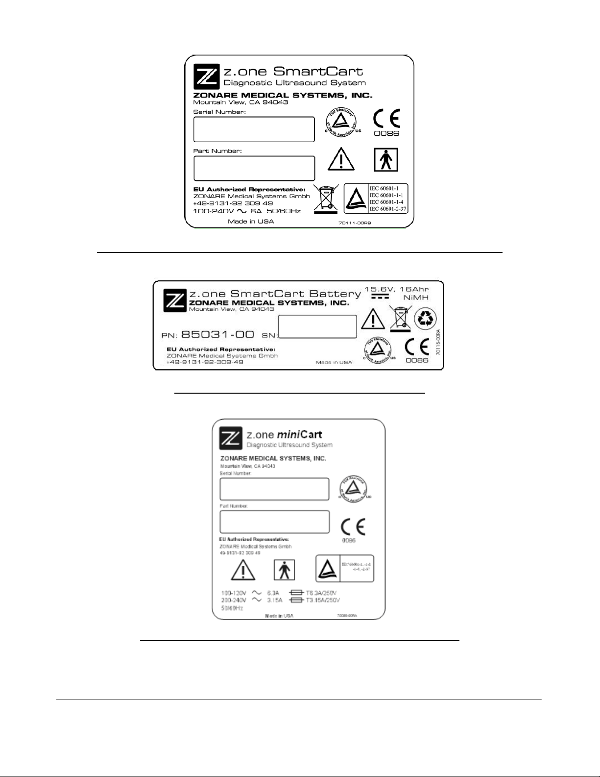
Figure 5: Label, 100V-240V SmartCart Rear Panel - Serial/Part No.
Figure 6: Label, SmartCart Z-Pak Battery
Figure 7: Label,
Q00169 Rev D Page 32 of 304
"Note: Copies are uncontrolled documents - For revision verification see the Master Docum e ntation List"
mini
Cart rear panel - Serial/Part No.
Page 33

Figure 8: Label, Linear Array Transducers - Serial/Part No.
Figure 9: Label, Curved Array Transducers - Serial/Part No.
Figure 10: Label, Endo Cavity Transducer - Serial/Part No.
Figure 11: Label, Phased Transducers - Serial/Part No.
Figure 12: Label, Specialty Transducers - Serial/Part No.
Q00169 Rev D Page 33 of 304
"Note: Copies are uncontrolled documents - For revision verification see the Master Docum e ntation List"
Page 34

Figure 13: Label, AC Power Battery Adapter
Figure 14: Label, AC Power Adapter Power Supply
Q00169 Rev D Page 34 of 304
"Note: Copies are uncontrolled documents - For revision verification see the Master Docum e ntation List"
Page 35

4 TOP-LEVEL PRODUCT OVERVIEW
4.1 Major Assembly Identification
SmartCart miniCart
Scan Engine Scan Module
Figure 15: Z.ONEUltra Major Assembly Illustrations
4.2 Transducers
Linear Curved Phased Endo-Cavity CW Aux TEE
Figure 16: Transducer Illustrations
Q00169 Rev D Page 35 of 304
"Note: Copies are uncontrolled documents - For revision verification see the Master Docum e ntation List"
Page 36

4.3 Accessory Components
USB Memory Stick Lithium-Ion Battery Pack 2-Pedal Footswitch
AC Power Adapter Battery Charger, 2-Bay
Figure 17: Accessories
Q00169 Rev D Page 36 of 304
"Note: Copies are uncontrolled documents - For revision verification see the Master Docum e ntation List"
Page 37

4.4 SmartCart Major Assemblies (shown with MTP Multi- probe Option)
Q00169 Rev D Page 37 of 304
"Note: Copies are uncontrolled documents - For revision verification see the Master Docum e ntation List"
Page 38

4.5 miniCart Major Assemblies
Q00169 Rev D Page 38 of 304
"Note: Copies are uncontrolled documents - For revision verification see the Master Docum e ntation List"
Page 39

4.6 SmartCart User Interface Controls (Overview)
Figure 18: SmartCart Keyboard Controls (Overview)
Figure 19: SmartCart User Interface (Version 1) Controls (Overview)
Q00169 Rev D Page 39 of 304
"Note: Copies are uncontrolled documents - For revision verification see the Master Docum e ntation List"
Page 40
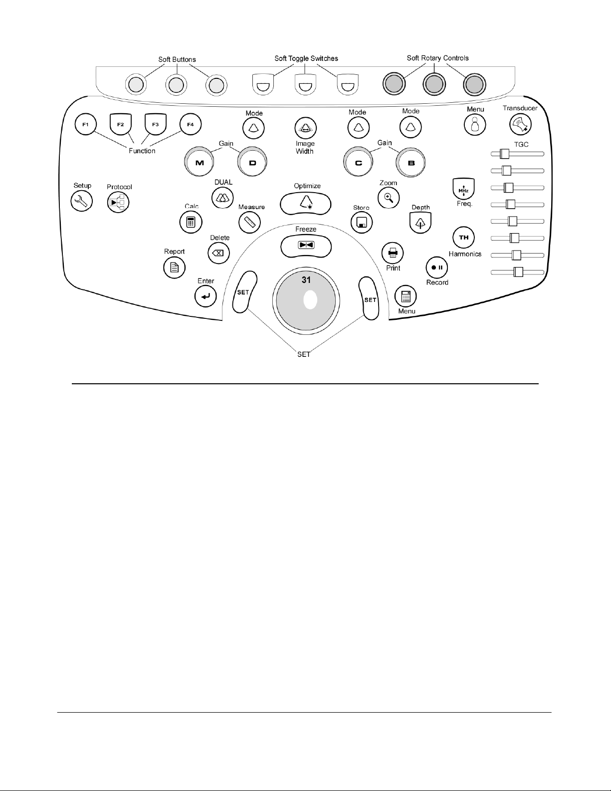
Figure 20: SmartCart User Interface (“Enhanced” version) Controls (Overview)
Q00169 Rev D Page 40 of 304
"Note: Copies are uncontrolled documents - For revision verification see the Master Docum e ntation List"
Page 41

4.7 Scan Engine User Interface Controls (Overview)
Figure 21: Scan Engine User Interface Controls (Overview)
Q00169 Rev D Page 41 of 304
"Note: Copies are uncontrolled documents - For revision verification see the Master Docum e ntation List"
Page 42
4.8 SmartCart User Interface Controls (Detailed) – Version 1
Figure 22: SmartCart User Interface Layout – Version 1
Q00169 Rev D Page 42 of 304
"Note: Copies are uncontrolled documents - For revision verification see the Master Docum e ntation List"
Page 43

4.8.1 SmartCart User Interface Functions (Version 1)
Number System Control Description
1 DGC Slidepots Changes gain of image at discrete depths
2
GAIN Changes overall gain for applicable modality (outer ring)
3 DEPTH Adjusts (Up/Down) the imaging depth of the display
4 FREQUENCY Enables increasing/decreasing transmit frequency
5 HARMONICS Activates tissue harmonics imaging mode
6 FREEZE Halts or re-starts active imaging on the display
7 PRINT Sends current image to device(s) previously specified in System
Setup menu (Local Printer, DICOM printer, DICOM store).
8 STORE 1/2 Sends current image to device(s) previously specified in System
Setup menu (Local Printer, DICOM printer, DICOM store).
9 OPTIMIZE Dual function: “ZST” Sound Speed Correction and/or
“AutoOpt” (DGC)
10 MEASURE Multi function key:
Q00169 Rev D Page 43 of 304
"Note: Copies are uncontrolled documents - For revision verification see the Master Docum e ntation List"
Page 44

1) Brings up dynamic caliper (live) or Calc menu (frozen)
2) Toggles on/off the Auto-Dop Trace function, in PW Doppler
mode
11 “SET” Used to toggle the function of active items on display (equivalent
to a “mouse click”)
12 CALC Brings up Calculation tools on the display
13 DELETE (Calc) Deletes active Calculation tool from the display
14 REPORT (Calc) Initiates a Calculation report
15 ENTER (Calc) / Shared function key:
1) Ends the current Calculation process, and produces a result
2) Toggles between the (A) or (B) image, as the “Active”
(selected) image, in DUAL mode
16 DUAL Mode Activates/deactivates DUAL imaging mode
17 B B- Mode (Tissue mode)
18 C Color (Doppler) Mode, toggle activates/de-activates
19 D Doppler (Pulsed Wave), toggle activates/de-activates
20 M M-Mode (tissue motion), toggle activates/de-activates
Q00169 Rev D Page 44 of 304
"Note: Copies are uncontrolled documents - For revision verification see the Master Docum e ntation List"
Page 45
21 ZOOM Initiates the variable image magnification process
22 TAB Advances through four (4) on-screen menus (Imaging, Presets,
Patient Info, Tools)
23 Menu Control Functions like a computer mouse or joystick, for scrolling through
on-screen menu selections (up/down), and modifying settings for
selected on-screen functions (left/right)
24 SELECT Activates currently highlighted selection in the on-screen menu.
25 BACK Returns back one window, in the on-screen display menu
26 F1 –F4 Function keys, user configurable in System Setup menu
27 Trackball Used for positioning the cursor, defining size/position of ROI in
color mode, positioning measurement tools, reviewing cine-loop
images and navigating form/tables/worksheets/reports
28 Image Width Enables changing the width (angle) of the active scanning area of
the B-Mode sector, to maximize frame rate
29 Record Shared function key:
1) Momentary Press: Generates the remote print/record trigger
signal out of the optional AVED box
2) Extended Press: Ejects the DVD/CD from the internal DVD
drive in the SmartCart
Q00169 Rev D Page 45 of 304
"Note: Copies are uncontrolled documents - For revision verification see the Master Docum e ntation List"
Page 46

30 Protocol Used to enable controls for selecting timing (time or cardiac
cycle) for Cine Clip stores.
31 Transducer (MTP) Used to bring the available transducers to the OLED display
windows, for selection of a desired transducer from the 3-Port
MTP panel.
32 Mode Keys (4) Mode functional assignment keys, User configurable in System
Setup menu
Q00169 Rev D Page 46 of 304
"Note: Copies are uncontrolled documents - For revision verification see the Master Docum e ntation List"
Page 47

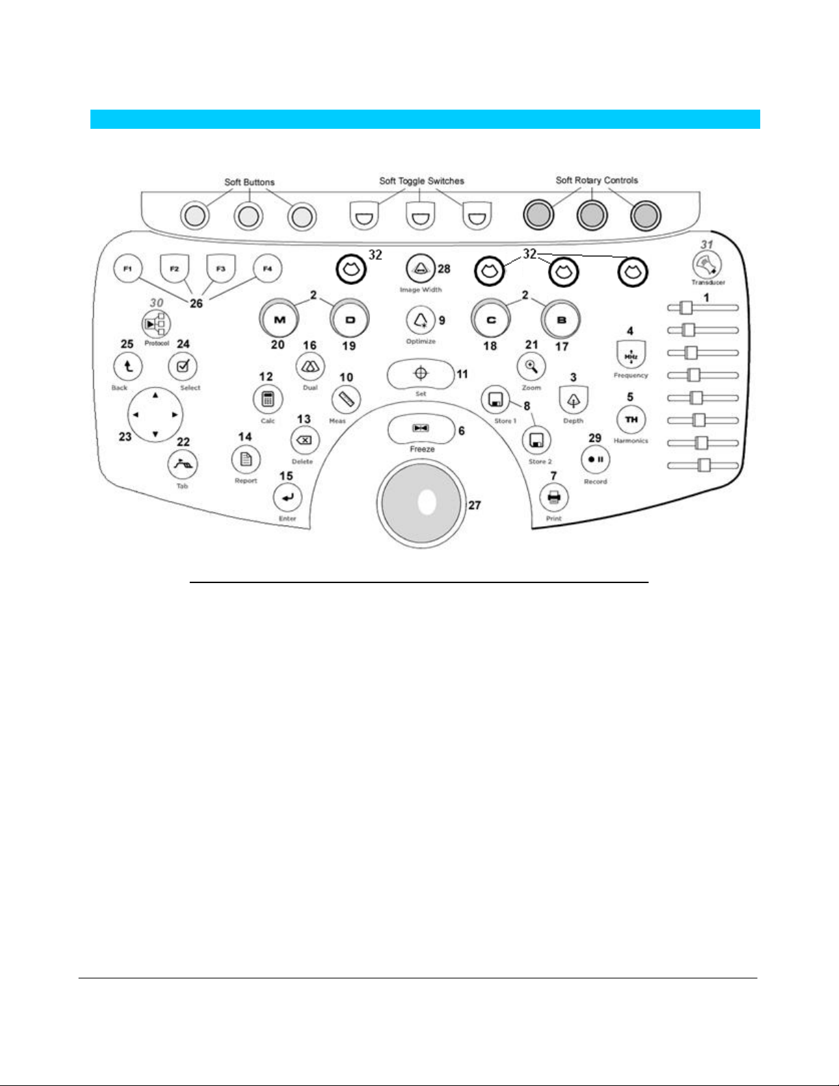
4.9 SmartCart User Interface Controls (Detailed) – “Enhanced” Version (2)
Figure 23: SmartCart User Interface Layout – “Enhanced” Version (2)
Q00169 Rev D Page 47 of 304
"Note: Copies are uncontrolled documents - For revision verification see the Master Docum e ntation List"
Page 48

4.9.1 SmartCart User Interface Functions (Enhanced Version)
Number System Control Description
1 F1 –F4 Function keys, user configurable in System Setup menu
2 Mode Keys (3) Mode functional assignment keys, User configurable in System
Setup menu
3 Image Width Enables changing the width (angle) of the active scanning area of
the B-Mode sector, to maximize frame rate
4 Exam Type Brings up Exam Type/Presets configuration menu, and 6 user
Preset setting to OLED display windows
5 Transducer (MTP) Used to bring the available transducers to the OLED display
windows, for selection of a desired transducer from the 3-Port
MTP panel.
6
GAIN Changes overall gain for applicable modality (outer ring)
7 M M-Mode (tissue motion), toggle activates/de-activates
8 D Doppler (Pulsed Wave), toggle activates/de-activates
9 C Color (Doppler) Mode, toggle activates/de-activates
Q00169 Rev D Page 48 of 304
"Note: Copies are uncontrolled documents - For revision verification see the Master Docum e ntation List"
Page 49

10 B B- Mode (Tissue mode)
11 DGC Slidepots Changes gain of image at discrete depths
12 SETUP Used to bring up the SYSTEM SETUP configuration menu.
13 Protocol Used to enable controls for selecting timing (time or cardiac
cycle) for Cine Clip stores.
14 REPORT (Calc) Brings up the Calculation report page
15 CALC Brings up the Calculations menu page.
16 DUAL Mode Activates/deactivates DUAL imaging mode
17 ZOOM Initiates the variable image magnification process
18 DEPTH Adjusts (Up/Down) the imaging depth of the display
19 Record Shared function key:
1) Momentary Press: Generates the remote print/record trigger
signal out of the optional AVED box
2) Extended Press: Ejects the DVD/CD from the internal DVD
drive in the SmartCart
20 HARMONICS Activates tissue harmonics imaging mode
Q00169 Rev D Page 49 of 304
"Note: Copies are uncontrolled documents - For revision verification see the Master Docum e ntation List"
Page 50

21 FREQUENCY Enables increasing/decreasing transmit frequency
22 ENTER (Calc) / Shared function key:
1) Ends the current Calculation process, and produces a result
2) Toggles between the (A) or (B) image, as the “Active”
(selected) image, in DUAL mode
23 DELETE (Calc) Deletes active Calculation tool from the display
24 MEASURE Multi function key:
1) Brings up dynamic caliper (live) or Calc menu (frozen)
2) Toggles on/off the Auto-Dop Trace function, in PW Doppler
mode
25 OPTIMIZE Dual function: “ZST” Sound Speed Correction and/or
“AutoOpt” (DGC)
26 STORE Sends current image to device(s) previously specified in System
Setup menu (Local Printer, DICOM printer, DICOM store).
27 PRINT Sends current image to device(s) previously specified in System
Setup menu (Local Printer, DICOM printer, DICOM store).
28 MENU Brings up access to four (4) on-screen menus (Imaging, Presets,
Patient Info, Tools)
29 “SET” Used to toggle the function of active items on display
(equivalent to a “mouse click”)
Q00169 Rev D Page 50 of 304
"Note: Copies are uncontrolled documents - For revision verification see the Master Docum e ntation List"
Page 51

30 FREEZE Halts or re-starts active imaging on the display
31 Trackball Used for positioning the cursor, defining size/position of ROI in
color mode, positioning measurement tools, reviewing cine-loop
images and navigating form/tables/worksheets/reports
Q00169 Rev D Page 51 of 304
"Note: Copies are uncontrolled documents - For revision verification see the Master Docum e ntation List"
Page 52

4.10 SmartCart & miniCart Keyboard Controls (Detailed)
Figure 24: SmartCart Keyboard Layout
Figure 25:
mini
Cart Keyboard Layout
Q00169 Rev D Page 52 of 304
"Note: Copies are uncontrolled documents - For revision verification see the Master Docum e ntation List"
Page 53

KEYBOARD: SPECIAL FUNCTION CONTROLS
Key System Control Description
NEW PATIENT
CURRENT EXAM
PG BACK
PG FWD
FIRST LAST
DELETE
FORMAT
ARCHIVE
END EXAM
DICOM QUEUE
ECG
SERVICE
BX GUIDE
(Arrow)
BODY PATTERN
This is a toggle key. The first press will display the Patient Information page.
The second press will return to the imaging display.
If there is an exam in progress, pressing this key will display the in-progress
exam's images, most recently stored image displayed first. If there is no exam
in progress, pressing this key will have no effect.
This key only works when in in-progress exam review or archived exam review.
Pressing this key will display the previous image, or page of images if in a
multi-image display format. Once the first page is reached, the key press will
have no effect.
This key only works when in in-progress exam review or archived exam review.
Pressing this key will display the next image, or page of images if in a multiimage display format. Once the last page is reached, the key press will have
no effect.
This key only works when in in-progress exam review or archived exam review.
Pressing this key will toggle between the first stored image (or first page of
images in a multi-image display format) and the last stored image (or last page
of images in a multi-image display format).
This key only works when in in-progress exam review or archived exam review.
When an image has been selected, pressing the Delete key will tag the image
for deletion by drawing a red X through it. If the selected image already has
been tagged for deletion (red X) pressing the Delete key will remove the red X,
untagging the image.
This key only works when in in-progress exam review or archived exam review.
Pressing this key will toggle between the following image formats: 2 x 2,
displaying 2 rows of 2 images (4 images); 3 x 2, displaying 2 rows of 3 images
(6 images); and a full-size image.
This is a toggle key. The first press will display the Patient Selection Table.
The second press will return to imaging.
When an exam is in progress, pressing the End Exam key will close the exam.
If no exam is in progress, pressing this key will have no effect.
This is a toggle key. The first press will display the DICOM queue. The
second press will return to imaging.
CARDIAC Option Systems ONLY: This is a toggle key. The pressing of this
key will activate ECG operation and display the ECG trace on the monitor. A
repeat press will turn off this function.
This is a dual-function key. A “quick” momentary press is a shortcut to bring
up the USER DIAGNOSTIC PANEL screen. An “extended” press will trigger a
capture of a set of current LOG files to the internal archive
This is a toggle key. The first press will display the biopsy needle path guide.
The second press will remove the biopsy needle path guide.
This is a toggle key. It will only work when the image is frozen. Pressing the
key when the image is frozen will display an arrow graphic in the middle of the
display.
This is a cycling key. Pressing the Body Pattern key will display a Body Pattern
for the Exam Type in use. Pressing the key will cycle through available Body
Patterns, including a blank.
Q00169 Rev D Page 53 of 304
"Note: Copies are uncontrolled documents - For revision verification see the Master Docum e ntation List"
Page 54

DEL WORD | DEL TEXT
SET | HOME
Pressing Del Text will remove all text annotations and arrow graphics
displayed. Pressing Shift+Del Word will delete the most recently entered text
annotation, whether it be free text, POT, or List entry.
Pressing Home will move the text annotation cursor to its default home
position. Pressing Shift+Set Home will set the current cursor position as the
new Home position.
TEXT
ALT GR
LONG TRANS SAG
COR
RT LT
PROX MID DIST
LIST 1
LIST 2
Pressing Text will display the text annotation cursor. Pressing Text again will
remove the text annotation cursor.
Alternate Graphics. Used in conjunction with the QWERTY keyboard, to
enable access to international characters.
This is a cycling key. Pressing this key will cycle between displaying LONG,
TRANS, SAG, and COR, for selection as pre-created text annotation.
This is a cycling key. Pressing this key will cycle between displaying RIGHT
and LEFT, for selection as pre-created text annotation.
This is a cycling key. Pressing this key will cycle between displaying PROX,
MID, and DIST, for selection as pre-created text annotation.
Pressing List1 key will display a list of text items entered in List 2.
Pressing List 2 key will display a list of text items entered in List 2.
Q00169 Rev D Page 54 of 304
"Note: Copies are uncontrolled documents - For revision verification see the Master Docum e ntation List"
Page 55

4.11 Scan Engine User Interface Controls (Detailed)
Figure 26: Scan Engine User Interface Layout (Detailed)
4.11.1 Scan Engine User Interface Functions
Number System Control Description
1 GAIN Controls the overall gain for B-Mode and Color Doppler
2 DGC Turns on the virtual DGC graphic
Q00169 Rev D Page 55 of 304
"Note: Copies are uncontrolled documents - For revision verification see the Master Docum e ntation List"
Page 56

3 DEPTH Adjusts the imaging depth shown on the display
4, 16 FREEZE Halts or re-starts active imaging
5, 17 STORE Stores current image to the internal archive storage and sends
images to device(s) previously specified in System Setup menu
(DICOM printer, DICOM store, local Printer). When USB digital
printer is selected, key press initiates sending a printed image to
the B/W (or Color) printer
6 PRINT Configurable for same functionality as STORE button above
7 MEASURE Multi function key:
1) Brings up dynamic caliper (live) or Calc menu (frozen)
2) Toggles on/off the Auto-Dop Trace function, in PW Doppler
mode
8 “SET” Used to toggle a selected item/function on-screen
8 C Color (Doppler) Mode, Activates/de-activates
10 PW Pulsed Wave (Doppler), Activates/de-activates
11 M M-Mode (tissue motion), Activates/de-activates
Q00169 Rev D Page 56 of 304
"Note: Copies are uncontrolled documents - For revision verification see the Master Docum e ntation List"
Page 57

12 F1, F2 Function keys, user configurable in System Setup menu
13 OPTIMIZE Dual function: “ZST” Sound Speed Correction and/or
“AutoOpt” (DGC)
14 TAB Advances through four (4) on-screen main menus (Imaging,
Presets, Patient Info, Tools)
15, 16 see item 4 and 5 above
17 SELECT Activates the currently highlighted selection in the on-screen
menu.
18 BACK Returns back one window, in the on-screen display menu
19 MODE Brings up the active scanning mode (C, PW, M) selection screen
20 Menu Control Functions like a computer mouse or joystick, for scrolling through
on-screen menu selections (up/down), and modifying settings for
selected on-screen functions (left/right)
21 Trackball Used for positioning the cursor, defining size/position of ROE in
color mode, positioning measurement tools, reviewing cine-loop
images and navigating form/tables/worksheets/reports
Q00169 Rev D Page 57 of 304
"Note: Copies are uncontrolled documents - For revision verification see the Master Docum e ntation List"
Page 58

4.12 SmartCart Rear I/O Panel: Layout & Functional Definitions
Figure 27: SmartCart Rear I/O Panel
4.12.1 Functions: I/O Connectors
# Function Direction
1 DVI Digital Video (Using HDMI connector) Output
2 USB Ports (4) Input/Output
3 Ethernet 10/100BaseT - (Network) Input/Output
4.13 miniCart I/O Connections: Layout & Functional Definitions
Figure 28:
mini
Cart USB Hub Connections
4.13.1 Functions: I/O Port Connectors
Jack # Function Direction
J1, J2 USB Ports - Hub Input/Output
Q00169 Rev D Page 58 of 304
"Note: Copies are uncontrolled documents - For revision verification see the Master Docum e ntation List"
Page 59
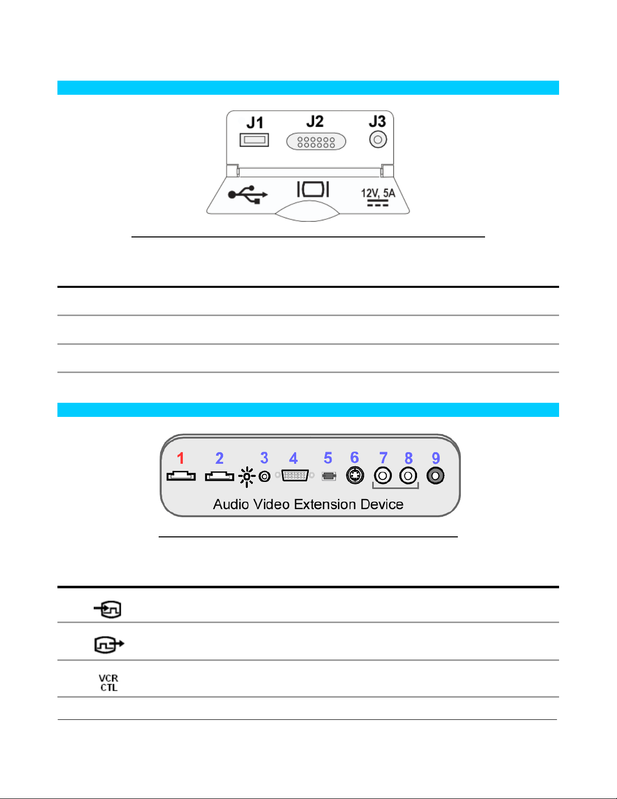
4.14 Scan Engine/Scan Module Rear I/O Ports: Layout & Functional Definitions
Figure 29: Scan Engine/Scan Module Rear I/O Connections
4.14.1 Functions: I/O Port Connectors
Jack # Function Direction
J1 USB Port Input/Output
J2 DVI Video - – [HDMI connector] Output
J3 +12VDC Input - (Zonare AC Power Adapter only!) Input
4.15 AVED: Audio-Video Extension Device - I/O Panel: (Option)
Figure 30: AVED Option - I/O Panel (SmartCart)
4.15.1 Functions: I/O Connectors
# Function Direction
1 DVI Digital Video/Audio (Using HDMI connector) Input
2 DVI Digital Video (Using HDMI Connector) Output
3 VCR/Print Remote Triggers – 2 discrete signals (3.5mm) Output
Q00169 Rev D Page 59 of 304
"Note: Copies are uncontrolled documents - For revision verification see the Master Docum e ntation List"
Page 60

4 VGA Video (Analog) Output
5 TOS LINK Audio (Digital) Output
6 S-Video (Analog) - (800x600 mode only!) Output
7 Audio Out – Right (Analog) Output
8 Audio Out – Left (Analog) Output
9 Composite Video (Analog) - (800x600 mode only!) Output
Q00169 Rev D Page 60 of 304
"Note: Copies are uncontrolled documents - For revision verification see the Master Docum e ntation List"
Page 61

5 SYSTEM UNCRATING & INSTALLATION PROCEDURES
5.1 Product Shipment
Shipping containers should be inspected for damages, and the “Tip-n-Tell” indicator for signs of
mishandling during shipment. If any problems are found, immediately notify the shipping carrier. All
installation and set-up of equipment should be done following official ZONARE product installation
procedures.
5.2 Electrical Requirements
Standard grounded (3-Prong) 110-120 VAC, 15 amp, 60Hz. wall outlets (or proper 220-240 VAC
outlets for systems configured for these power requirements) are required for the Z.ONEUltra
Diagnostic Ultrasound System.
5.3 Environmental and Space Requirements
The Z.ONEUltra Diagnostic Ultrasound System may be located anywhere within the facility, as long
as there is adequate power outlets and remote network connectivity (at facilities utilizing a DICOM
print/storage device hook-up).
5.4 Uncrating
5.4.1 SmartCart:
STEPS:
1. Prior to opening any packaging, inspect the “Tip-n-Tell” indicator (attached to the outside of
the main shipping box) for signs that the Z.ONEUltra has been subjected to shock or tilt
conditions during shipment.
2. Also inspect the shipping container for any visual signs of rough handling or abuse during
shipment.
3. Make notes of any discrepancies, and immediately report to the shipping carrier and to
ZONARE’s shipping department representative.
4. Remove all banding straps surrounding the cardboard main shipping container.
5. Lift off the top cover portion of the main cardboard shipping container, and set aside.
6. Remove the small boxes (containing the Z.ONEUltra transducers and Scan Engine) from the
inner storage box area (resting atop the SmartCart).
7. Lift the inner storage box upwards, and remove it from the main shipping container.
8. Grasping the sides, slide the cardboard main shipping box upwards, exposing the Z.ONEUltra.
Continue lifting until the cardboard box can be completely removed, and set aside.
Q00169 Rev D Page 61 of 304
"Note: Copies are uncontrolled documents - For revision verification see the Master Docum e ntation List"
Page 62

Figure 31: Main shipping container removal
9. Remove the clear packing tape that is used to secure the foldable wooden loading ramp in its
upward-facing shipping position. Lower the ramp on its hinges.
Figure 32: Loading ramp lowering
10. Remove the clear packing tape that secures the front support to the base during shipping. Grasp
the removable front support section of the wooden shipping base (at the bottom-front of the
system), pull it directly outwards away from the Z.ONEUltra, and set aside.
Figure 33: Removable section of shipping base
11. Remove the plastic packaging bag to expose the Z.ONEUltra.
Q00169 Rev D Page 62 of 304
"Note: Copies are uncontrolled documents - For revision verification see the Master Docum e ntation List"
Page 63

Figure 34: Removing protective storage bag
12. Pull up to the top position on the brake pedal (at the front of the Z.ONEUltra), to release
locking of the SmartCart’s wheels.
Figure 35: Brake release of wheels
13. Rotate the wheels from their 90 degree angled storage position, to be inline with the loading
ramp and enable rolling the system out of crate.
14. Being careful to control the system’s momentum, roll the Z.ONEUltra down the ramp, and out
of crate.
15. Remove all protective plastic wrap and foam packaging materials.
16. Inspect the entire Z.ONEUltra for damage, paying close attention to the LCD display on the
SmartCart.
17. Move the Z.ONEUltra to the installation area.
5.4.2 miniCart:
STEPS:
1. Prior to opening any packaging, inspect the “Tip-n-Tell” indicator (attached to the outside of the
main shipping box) for signs that the Z.ONEUltra has been subjected to shock or tilt conditions
during shipment.
Q00169 Rev D Page 63 of 304
"Note: Copies are uncontrolled documents - For revision verification see the Master Docum e ntation List"
Page 64

2. Also inspect the shipping container for any visual signs of rough handling or abuse during
shipment.
3. Make notes of any discrepancies, and immediately report to the shipping carrier and to
ZONARE’s shipping department representative
4. Remove all banding straps surrounding the cardboard main shipping container.
5. Grasping the sides, slide the cardboard main shipping box upwards, exposing the miniCart and
container contents. Continue lifting until the cardboard box can be completely removed, set aside.
6. Remove the plastic covering and shrink wrap from the miniCart and container contents.
7. Remove the small boxes (containing the Z.ONEUltra transducers and Scan Engine) from the
container.
8. On the container base, remove or cut the clear packing tape that secures the rear flap and unfold
the rectangle cardboard support at the rear of the system. This rear flap is partially glued and will
require a slight pull to release. This will provide an exit and slight ramp for removing the
miniCart from the base.
9. Unlock the brakes (two front wheels), and firmly grasp the rear handle.
10. Being careful to control the system’s momentum, gently roll/lift the system down the ramp and
off the base.
Note: Make sure that you are supporting the weight of the system while removing as the cardboard
mock-ramp is not designed to support the full weight of the miniCart
Q00169 Rev D Page 64 of 304
"Note: Copies are uncontrolled documents - For revision verification see the Master Docum e ntation List"
Page 65

11. Remove all protective plastic wrap and foam packaging materials.
12. Inspect the entire Z.ONEUltra for damage, paying close attention to the LCD display on the
miniCart.
13. Move the Z.ONEUltra to the installation area.
5.5 Mechanical Verification
STEPS:
1. Perform a check to verify proper operation of all of the following mechanical components.
Ensure wheels and brakes function properly
Raise and lower the Cart height adjuster (pull release lever located on the right of the
system), to verify smooth operation and positive locking
Ensure the LCD display monitor rotates and adjusts properly
Place the Scan Engine onto the Scanner Deck and pull the Scan Engine towards you, to
ensure full docking engagement.
Immediately report any mechanical discrepancies to ZONARE.
5.6 System Installation:
5.6.1 Initial Checks
STEPS
:
1. Check to ensure all peripherals, software level, and serial numbers correspond with sales order.
Make note of any missing items or discrepancies, and immediately report to ZONARE.
2. Check the two AC power rating labels, located by the system power receptacle and inside the
rear cover by the AC outlet box, to verify power rating matches AC power level present at
installation site.
3. Measure voltage at AC receptacle, at install site, to verify proper power levels are present.
WARNING
To prevent possible damage to the electronics of the Scan Engine from condensation, the
following warning must be observed:
Q00169 Rev D Page 65 of 304
"Note: Copies are uncontrolled documents - For revision verification see the Master Docum e ntation List"
Page 66

If the Scan Engine has been subjected to an environment during shipping/transport that differs
greatly in temperature and/or humidity, from the environment where it has been moved for
installation/intended operation, the unit should be allowed to stand for a period of no less than
30 minutes prior to inserting battery or powering on.
5.6.2 Installing the Battery Pack, into the Scan Engine
STEPS:
1. Remove the battery pack from its shipping materials
2. Correctly orient the battery pack and slide fully into the battery port on the Scan Engine, until
fully seated (latched).
Figure 36: Battery Pack Installation
5.6.3 Docking Scan Engine (or Scan Module) into SmartCart
STEPS:
1. Place the Scanner in the molded area on the docking plate, so that it will align itself in the
cradle.
2. Gently pull the Scanner towards you until you hear a clicking sound from the release lever
securing the system into place.
Figure 37: Scanner Docking in SmartCart
Q00169 Rev D Page 66 of 304
"Note: Copies are uncontrolled documents - For revision verification see the Master Docum e ntation List"
Page 67
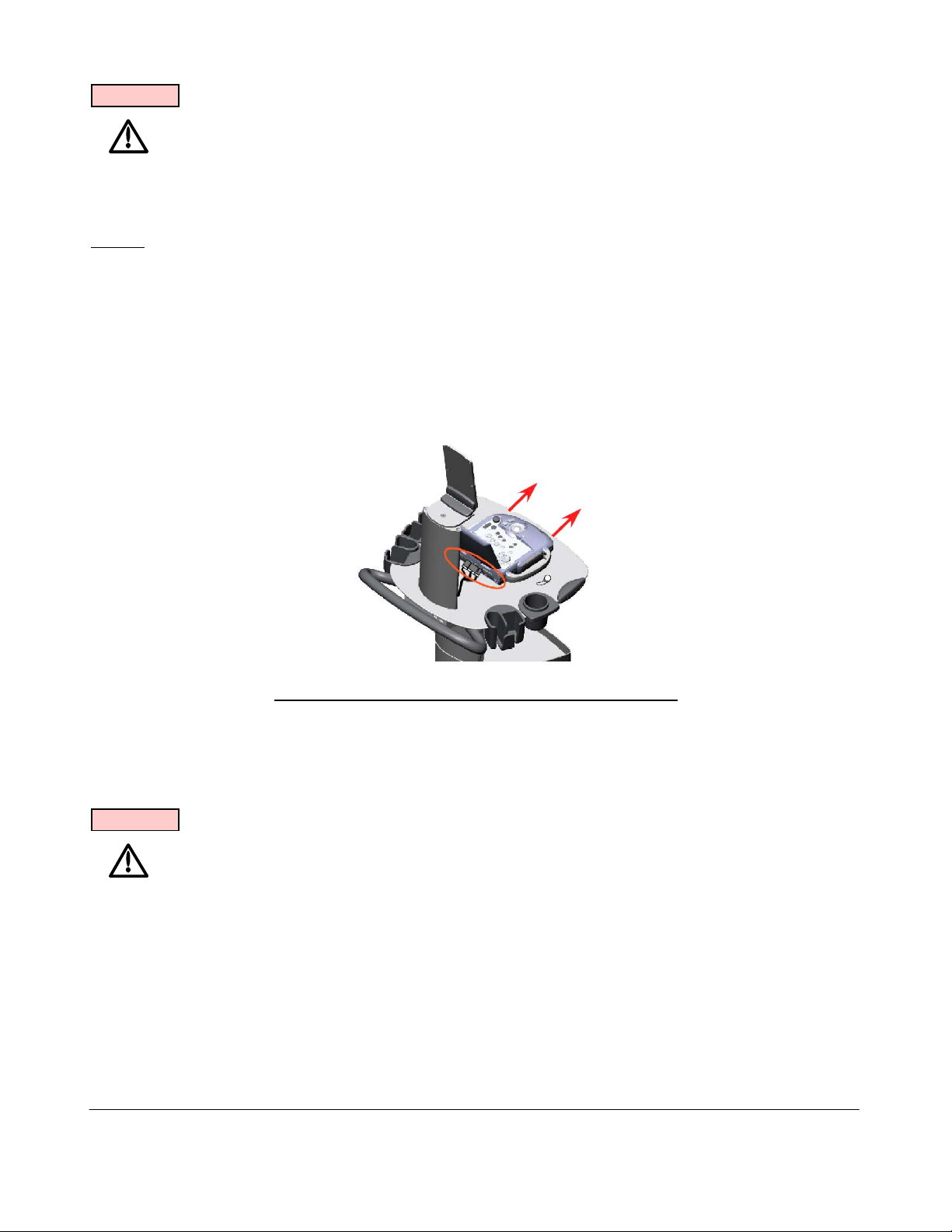
WARNING
To maintain the integrity of the electronic equipment within the Z.ONEUltra, it is critically
important that a specific sequence be followed at all times, for turning ON or OFF system
power. The sequences listed below should always be followed.
5.6.4 Docking Scan Engine on miniCart
STEPS:
1. Hold the Scan Engine centered (horizontally) and rearward above the docking plate on the
miniCart.
2. Line up the tracks on the top surface of docking plate with the tracks on the bottom of the Scan
Engine.
3. While resting flat on the docking plate surface, gently slide the scan engine directly towards
you (forward), to engage it on the docking latches. Continue to slide the Scan Engine towards
you, until a positive audible "click" is heard.
Figure 38: Scan Engine to
mini
Cart Docking
4. Open the I/O access door at the rear of the Scan Engine, and connect the docking connector
cable assembly to the mating connectors on the Scan Engine
WARNING
To maintain the integrity of the electronic equipment within the Z.ONEUltra, it is critically
important that a specific sequence be followed at all times, for turning ON or OFF system
power. The sequences listed below should always be followed.
5.6.5 Powering-ON the Z.ONEUltra
NOTE: The miniCart receives direct AC power (no manual circuit breaker). Therefore anytime the
main AC power cord is connected to an active outlet and the other end connected at the
rear panel of the system, source power is active.
Q00169 Rev D Page 67 of 304
"Note: Copies are uncontrolled documents - For revision verification see the Master Docum e ntation List"
Page 68

5.6.5.1 SmartCart Power-ON
STEPS:
1. Make sure the AC Main Circuit Breaker on the SmartCart is in the “1” (ON, pushed in on the
LEFT) position (see illustration below).
NOTE: The SmartCart has the ability to be powered by AC or battery (IF the Z-PAK
battery pack “Option” is ordered). When the SmartCart is fully charged the
battery should allow for normal system operation for more than 1 hour.
When the scan engine is docked into the SmartCart, its internal battery is subject
to being charged. If the SmartCart is being AC powered the Scan Engine will
utilize the main power supply, with source power coming from the AC input. If the
SmartCart is running on the Z-PAK battery the scan engine will be charged using
source power derived from the battery in the SmartCart.
2. Locate the power button on the front/left of the scan engine Scanner Deck. Press and release
the On/Off button to power on the Z.ONEUltra.
3. The Z.ONEUltra will take less than a minute to complete the normal power on sequence.
5.6.6 Powering-OFF the Z.ONEUltra System
NOTE: The miniCart receives direct AC power (no manual circuit breaker). Therefore anytime the
main AC power cord is connected to an active outlet and the other end connected at the
rear panel of the system, source power is active.
Q00169 Rev D Page 68 of 304
"Note: Copies are uncontrolled documents - For revision verification see the Master Docum e ntation List"
Page 69
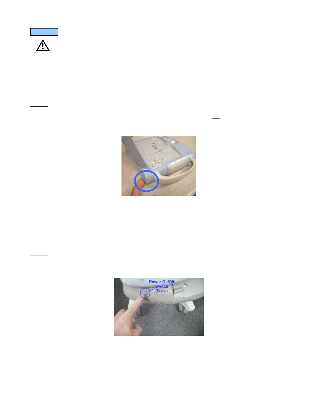
CAUTION
To ensure the integrity of the stored User parameters, and system configuration, the Power
ON/OFF button on the Scan Engine should always be used FIRST, as the method for shutting
down a fully operating
Z.ONEUltra (SmartCart and Scan Engine) system.
Failure to allow for a normal power-down sequence by the Scan Engine (such as by improperly
pulling out the AC power cord or toggling the AC circuit breaker on the SmartCart while the
Z.ONEUltra is still operating), may result in lost patient image data.
5.6.6.1 miniCart or Scan Engine (standalone) Power-OFF
STEPS:
1. Using the underside of your finger, gently press-and-release (do not “HOLD”) the green-
colored (rubber membrane) Power On/Off Switch at the back/left corner of the scan engine, to
initiate the start of a power OFF sequence.
Power On/Off
Swtich
NOTE: The system will NOT immediately power down, as the Scan Engine will perform a properly
ordered shutdown sequence (taking approximately 10 seconds).
2. A message should appear on the display within a few seconds, indicating the start of the
normal shutdown sequence.
5.6.6.2 SmartCart Power-OFF
STEPS:
1. Locate the power button on the front/left of the scan engine dock plate. Press and release the
On/Off button to begin the power down cycle on the Z.ONEUltra.
Q00169 Rev D Page 69 of 304
"Note: Copies are uncontrolled documents - For revision verification see the Master Docum e ntation List"
Page 70

Normally the SmartCart's main AC circuit breaker power is left “ON”, even when the
Z.ONEUltra has been shutdown from normal use. However if the SmartCart is being
transported the AC power can be turned OFF, by moving the circuit breaker to the “0” position
(pushed in on the RIGHT), prior to disconnecting the AC power cord from the wall outlet
5.6.7 AC Power Adapter: Use & Operation
WARNING
There are no User or Field Service repairable components within the AC Power Pack. Any
defective units should be returned to the Zonare factory for repair/replacement.
Standalone use (undocked from the SmartCart or miniCart) of the Scan Engine normally utilizes a
fully charged battery pack to power the unit. However to allow for extended standalone operation of
the Scan Engine, an AC Power Pack is available from Zonare as an alternate power source. The
output connector of the AC Power Pack is plugged into the DC power port on the rear of the Advanced
Hardware Scan Engine.
Figure 39: AC Power Adapter
Q00169 Rev D Page 70 of 304
"Note: Copies are uncontrolled documents - For revision verification see the Master Docum e ntation List"
Page 71

STEPS:
1. Power off the Scan Engine, and ensure it is being used remotely (undocked) from the
SmartCart or miniCart
2. Plug the small connector of the DC Adapter Cable, into the mating socket on the DC power
port, located at the back of the Scan Engine (inside the Rear I/O access door).
3. Connect the output connector of the DC Power Cable (out of the Power Supply) to the DC
Adapter Cable’s mating connector
4. Plug the AC Power Cable’s female connector into the socket on the Power Supply
5. Plug the other end of the AC Power Cable into an active AC wall outlet
6. Inspect the Power-On indicator LED, on the Power Supply brick, to ensure power is on
7. Power on the Scan Engine and begin normal operation
5.6.8 2-Bay Battery Charger: Use & Operation
WARNING
There are no User or Field Service repairable components within the 2-Bay Battery Charger.
Any defective units should be returned to the Zonare factory for repair/replacement.
The Lithium-Ion battery packs, used to power the Scan Engine during standalone (undocked) use,
have expected charge retention of approximately 1 hour (during full-use of the Scan Engine). The
battery pack is normally kept charged when the Scan Engine is docked within the SmartCart.
However to prepare multiple battery packs for standalone Scan Engine use, or to recalibrate battery
packs for maximum performance, a Zonare 2-Bay Battery Charger is available.
Part Number Description
Z311 2-Bay Battery Charger, Domestic (120V) Model
Z312 2-Bay Battery Charger, International (220V) Model
Q00169 Rev D Page 71 of 304
"Note: Copies are uncontrolled documents - For revision verification see the Master Docum e ntation List"
Page 72
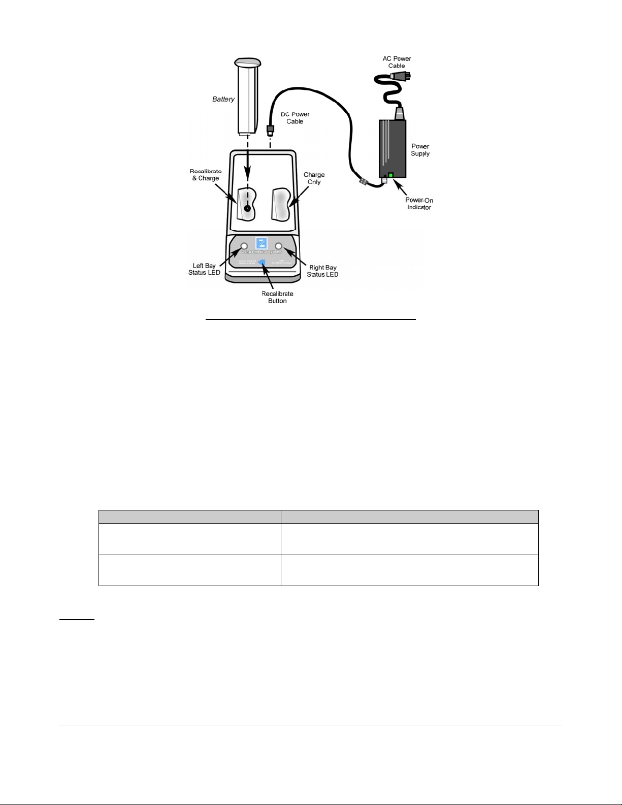
Figure 40: 2-Bay Battery Charger
5.6.8.1 “Recalibrating” Battery Packs
Recommended Intervals:
The Z.ONEUltra battery pack contains Lithium-Ion battery cells as well as an electronic “fuel”
gauge that keeps track of the charge and discharge cycles of the battery cells. During frequent
charge/discharge cycles, it is possible for this fuel gauge to loose its synchronization to the actual
charge remaining in the battery. When this happens, it is recommended to “Recalibrate” the
battery pack. This process will re-synchronize the fuel gauge to the battery cells.
It is recommended that the “Recalibrating” process be performed on each battery pack at the
following interval:
Usage Type Recommended “Recalibration” Interval
Battery packs heavily used in standalone
(undocked) Scan Engine mode
Every 30 charge cycles (or approximately once per month, maximum)
Battery packs used in Scan Engines
primarily operated docked in SmartCart
Every 2 to 4 months
STEPS
:
1. Connect the AC power cable to an active wall outlet, and connect the DC power cable between
the power supply and the 2-Bay Battery Charger
2. Insert the battery pack into the LEFT bay of the 2-Bay Battery Charger (Note: Only the LEFT
bay performs “Recalibration”)
3. Press the “Recalibrate” button on the 2-Bay Battery Charger
Q00169 Rev D Page 72 of 304
"Note: Copies are uncontrolled documents - For revision verification see the Master Docum e ntation List"
Page 73
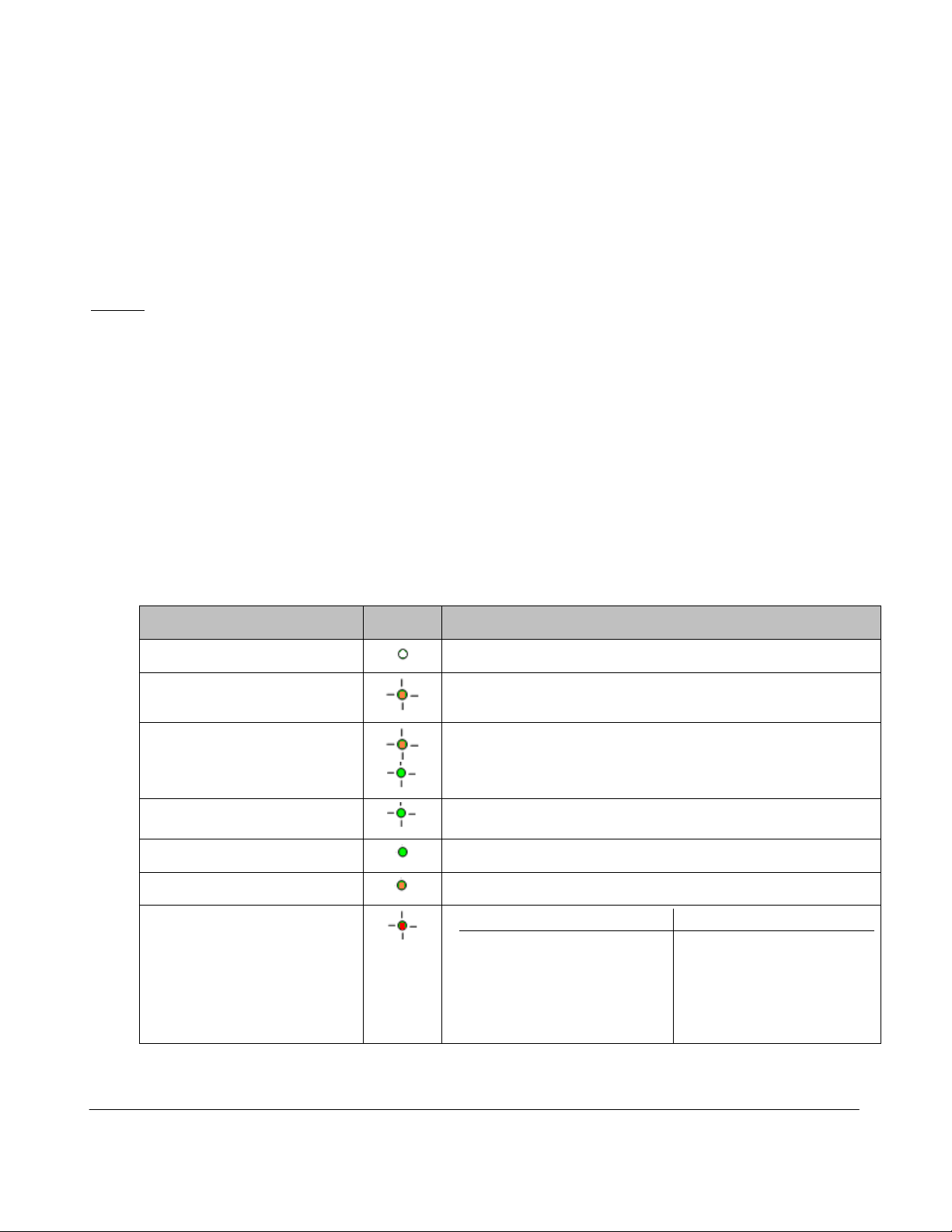
4. During the “Recalibrate” process, the left status LED flashes ORANGE. Once the
“Recalibrate” process is completed, this same LED will intermittently flash between ORANGE
and GREEN.
NOTE: - The “Recalibrate” process may require 14 hours to fully complete
- The battery pack should NOT be removed prior to completion of the “Recalibrate” process,
as the battery will be at an unknown level of charge
5.6.8.2 Charging Scan Engine Battery Packs
STEPS
:
1. Connect the AC power cable to an active wall outlet, and connect the DC power cable between
the power supply and the 2-Bay Battery Charger
2. Insert the battery pack into the EITHER bay of the 2-Bay Battery Charger
3. The charging cycle on the docked battery pack will automatically begin to execute
4. During the “Charging” process, the corresponding status LED flashes GREEN. Once the
“Charging” process is completed, this same LED becomes solid GREEN.
NOTE: - The “Charging” process, in the two bays of the unit, is performed in a “sequential” fashion. If
two battery packs are docked into the 2-Bay Battery Charger at the same time, the charger
will perform the complete charging sequence on one battery pack, before starting the
charging sequence on the second battery.
Status LED Condition LED Definition
OFF
ORANGE – “Flashing”
ORANGE/GREEN –
“Flashing”
No battery pack detected in bay
“Recalibration” of battery pack in progress
“Recalibration” complete (fully charged)
GREEN – “Flashing”
GREEN - Solid
ORANGE - Solid
RED – “Flashing” (Error)
“Charging” of battery pack in progress
“Charging” of battery pack complete
“Standby” – Battery in bay, waiting to be charged
Error Cause Resolution
- Foreign object in bays Clear charging area
- Battery pack defective Replace battery pack
- Excessive battery temp Remove battery to cool
[65oC / 149oF]
Q00169 Rev D Page 73 of 304
"Note: Copies are uncontrolled documents - For revision verification see the Master Docum e ntation List"
Page 74

5.7 Transporting - Shipping the Scan Engine/Scan Module
STEPS:
1. If a transducer is attached to Scanner, disconnect it and store in an appropriately safe/protected
manner
2. Undock the Scanner from the SmartCart/miniCart
3. Ensure that the Scanner is powered off
4. Remove the battery pack from the Scanner
CAUTION
To prevent possible damage to the unit, the battery must be REMOVED from the Scan
Engine prior to transport or shipment.
5. For shipment, ensure that the Scanner is packaged in a suitably protective storage container
Q00169 Rev D Page 74 of 304
"Note: Copies are uncontrolled documents - For revision verification see the Master Docum e ntation List"
Page 75
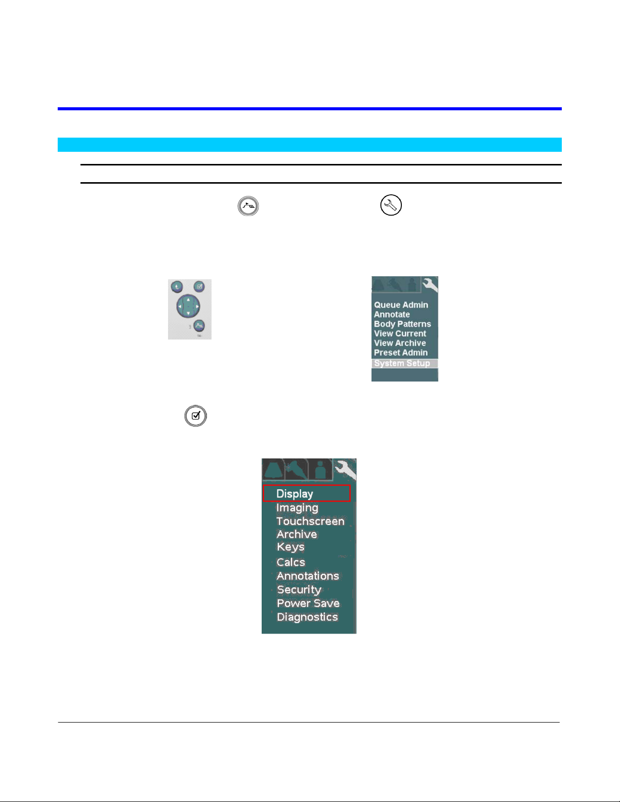
6 BASIC SYSTEM CONFIGURATION
6.1 Basic System Configuration Procedures
Entering “INSTITUTION” (Hospital) Name
1. Using the page TAB button (or press the “SETUP” key on Enhanced style UI
systems), advance menu screen to select Tools menu.
Menu Controls TOOLS Menu
2. Using the Menu Control, arrow down to backlight SYSTEM SETUP selection, and press the
SELECT button to bring up this menu.
SYSTEM SETUP Sub-Menu
3. Within the Display selection, use the Menu Control to backlight Institution selection, press
Select button to bring up this menu.
Q00169 Rev D Page 75 of 304
"Note: Copies are uncontrolled documents - For revision verification see the Master Docum e ntation List"
Page 76

DISPLAY Sub-Menu INSTITUTION Sub-Menu
4. Using the alpha-numeric keyboard, enter Institution name (Note: Field is limited to 20
character positions)
5. Place the arrow cursor over the APPLY soft-button displayed in this menu, and press the
SET key to save new settings.
Configuring “BARCODE” Setup
Within the Display selection, use the Menu Control to backlight Barcode selection, press
Select button to bring up this menu.
DISPLAY Sub-Menu BARCODE Sub-Menu
1. Under the Barcode Reader Device Assignment pull-down menu, select the listed device
corresponding to the active barcode reader currently attached to the USB ports on the
Z.ONEUltra.
2. Under the Barcode Data Settings pull-down menu, select the desired parameter to be linked
to for tracking patient exams:
Patient ID
Q00169 Rev D Page 76 of 304
"Note: Copies are uncontrolled documents - For revision verification see the Master Docum e ntation List"
Page 77

Accession Number
3. IF the Z.ONEUltra is setup to interface with a DICOM Worklist server for populating patient
exam scheduling, check the “Worklist Cache” option , within the Barcode Worklist Option
selection.
Enabling this option will result in the Z.ONEUltra using the scanned-in barcode parameter
(Patient ID, or Accession Number) for identifying the patient, to reference the cached
Worklist data for auto-populating various fields in the Patient Information page.
4. Place the arrow cursor over the APPLY soft-button displayed in this menu, and press the
SET key to save new settings.
Configuring “AUDIO/VIDEO” Setup
Within the Display selection, use the Menu Control to backlight Audio/Video selection, press
Select button to bring up this menu.
DISPLAY Sub-Menu AUDIO/VIDEO Sub-Menu
Q00169 Rev D Page 77 of 304
"Note: Copies are uncontrolled documents - For revision verification see the Master Docum e ntation List"
Page 78

Select the desired A/V setup parameters from the menu. This is done by using the trackball to
move the arrow pointer (in conjunction with the SET key), or using the TAB key on the
alpha-numeric keyboard to advance to each successive field, and the ENTER key to make
selections.
Refer to Section 18.8.1 of this manual for details on the procedure and settings to be used in
adjusting the Monitor on the SmartCart and miniCart (respectively).
System Display Mode: (Applicable to SmartCart systems ONLY)
This selection configures the format of the on-screen video. The selections allow for
increasing the amount of screen area used for the display of the main ultrasound image. This
enables increasing/decreasing the size of the image to suit the User. The two external video
format options available are:
Standard: Standard image size with Dashboard and Thumbnail images displayed
Image Only: Expanded image size (1280 x 1024) occupying entire 19” display (no
Dashboard/Thumbnails shown)
External Video Mode: (Applicable to SmartCart systems ONLY)
This selection configures the format of the digital video that will be produced at the external
HDMI connector (DVI video), on the rear panel of the SmartCart. The output format is
configurable to allow for matching the target peripheral device (external DVI monitor, etc).
The two external video format options available are:
Standard: 1280 x 1024 format (entire screen of SmartCart) – No S-Video/Composite
output on AVED box.
Image Only: 800 x 600 format (image area only) - Supports S-Video/Composite on
AVED box.
Once all the desired values have been selected, place the arrow cursor over the APPLY soft-
button displayed in this menu, and press the SET key to save new settings.
Q00169 Rev D Page 78 of 304
"Note: Copies are uncontrolled documents - For revision verification see the Master Docum e ntation List"
Page 79

Entering “TIME/REGION” Information
1. Within the Display selection, use the Menu Control to backlight Time/Region selection, press
Select button to bring up this menu.
DISPLAY Sub-Menu TIME (DATE) Sub-Menu
2. Using the alpha-numeric keyboard, enter in the current date/time information. The TAB key
on the alpha-numeric keyboard is used for advancing to each successive field.
3. Place the arrow cursor over the APPLY soft-button displayed in this menu, and press the
SET key to save new settings.
Q00169 Rev D Page 79 of 304
"Note: Copies are uncontrolled documents - For revision verification see the Master Docum e ntation List"
Page 80
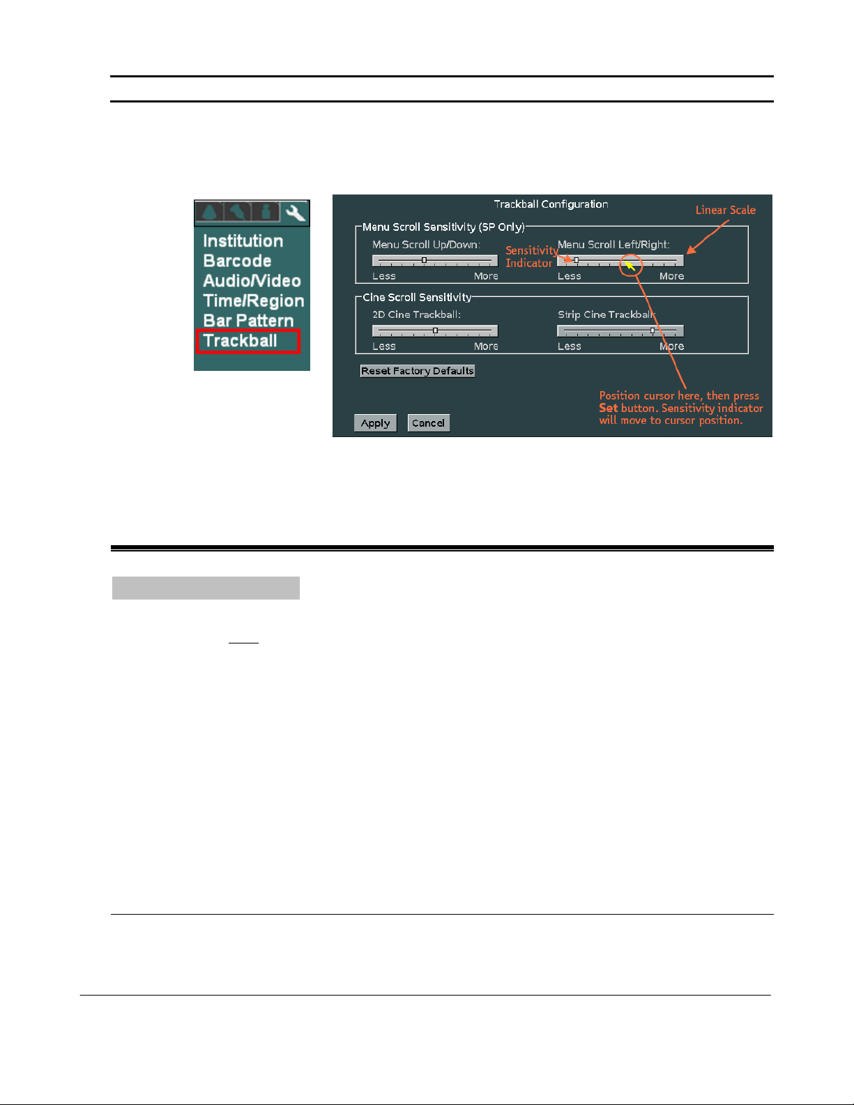
Entering “TRACKBALL” Configuration
1. Within the Display selection, use the Menu Control to backlight Trackball selection, press
Select button to bring up this menu.
DISPLAY Sub-Menu TRACKBALL Sub-Menu
Cine Trackball Configuration: (Applicable to SmartCart systems ONLY)
This menu allows for configuring the behavior of the trackball to users preferences,
independently for a variety of Cine modes. The configurable usages are as listed below:
Menu Scroll Sensitivity (Dual “SET” key style User Interface style Carts ONLY)
On the SP Cart (only), scrolling through menus and manipulating the settings for selected menu
offerings can be performed using the trackball. On the regular SmartCart (full U/I) systems, the
left/right-up/down OMNI control button is used for this same menu navigation process.
The following two configurable options allow for customizing the sensitivity of the trackball
response during those menu operations on the SP Cart.
Menu Scroll Up/Down:
Description: Threshold for speed of trackball movement by User when moving up/down
through offered menu selections.
Menu Scroll Left/Right:
Description: Threshold for speed of trackball movement by User when moving in a left/right
direction, for altering the setting of a currently selected menu function.
Q00169 Rev D Page 80 of 304
"Note: Copies are uncontrolled documents - For revision verification see the Master Docum e ntation List"
Page 81

Cine Scroll Sensitivity (All SmartCarts)
2D Cine Trackball: (B-Mode or B-Mode/Color modes)
Description: Controls the number of frames that are advanced in response to each swept
trackball movement by the User.
Strip Cine Trackball: (M-Mode or Spectral Doppler modes)
Description: Controls the rate at which the time axis sweep is advanced in response to each
sweep of trackball movement by the User.
Reset Factory Defaults::
Description: Restores all trackball setting in this menu, for Cine access, back to factory
defaults.
Configuring “IMAGING” Parameters
1. Using the page TAB button , advance menu screen to select Tools menu.
Menu Controls TOOLS Menu
2. Using the Menu Control, arrow down to backlight SYSTEM SETUP selection, and press the
SELECT button to bring up this menu, then select IMAGING sub-menu.
SYSTEM SETUP Sub-Menu IMAGING Sub-Menu
Q00169 Rev D Page 81 of 304
"Note: Copies are uncontrolled documents - For revision verification see the Master Docum e ntation List"
Page 82
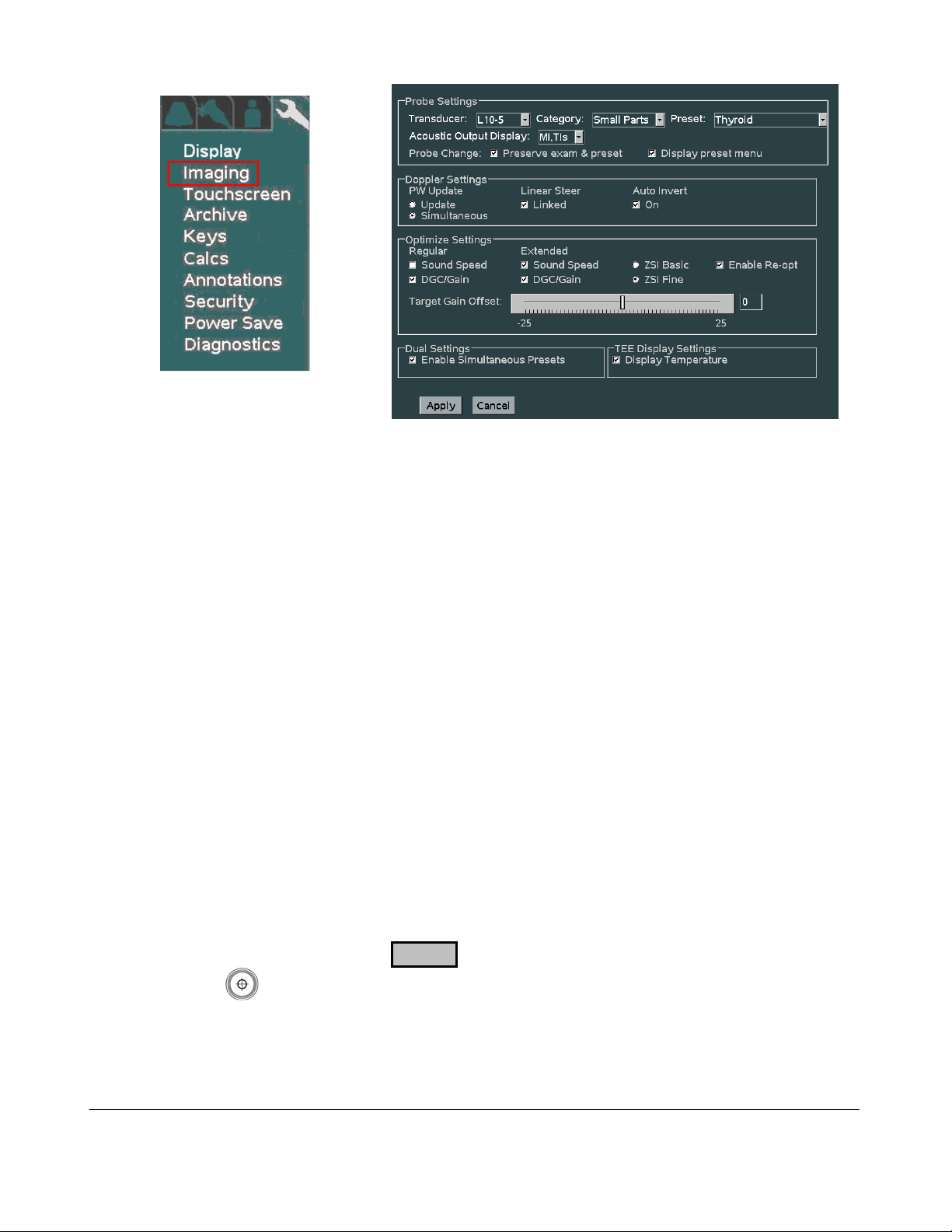
1. For each Transducer type in the pull-down menu, configure the power-up default application
type and preset type that are desired.
2. Select the desired behaviors to occur post transducer change:
Preserve Exam & Preset If checked, the system will retain the current Exam Type and
Preset, when transitioning to selection of a different active
transducer.
If unchecked, the system will use the user assigned default
Exam Type and Preset for each subsequent transducer, as it is
activated.
Display Preset Menu If checked, the OLED display panel will default to showing
Exam Preset options in the windows, upon a transducer
change.
If unchecked, the OLED display panel will default to showing
transducer selection options in the windows, upon a
transducer change
3. Select the desired default Doppler settings.
4. Select the desired default Auto-Opt/ZST settings
5. Select the desired “DUAL” mode preset behavior setting
6. Select whether TEE temperature sensor reading is desired for on-screen display
7. Place the arrow cursor over the APPLY soft-button displayed in this menu, and press the
SET key to save new settings.
8. Repeat the process above for all additional transducer types.
Q00169 Rev D Page 82 of 304
"Note: Copies are uncontrolled documents - For revision verification see the Master Docum e ntation List"
Page 83
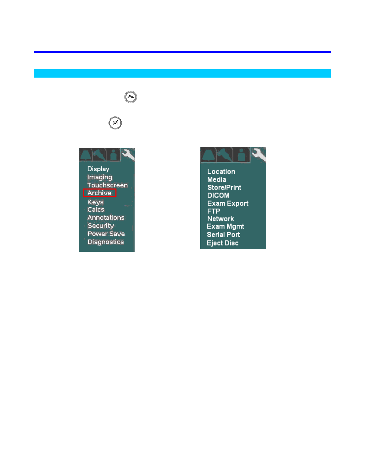
7 ARCHIVE MENU FUNCTIONS
7.1 “Media” & “Store/Print” Button Configuration
1. Using the TAB button
2. Using the Menu Control, arrow down to backlight the Archive selection, and press the
SELECT button to bring up this menu.
SYSTEM SETUP Sub-Menu ARCHIVE Sub-Menu
advance the menu screen to select TOOLS
In addition to configuration of the Archive functions, the following operations are also accessed under
this menu path.
LOCATION (site) specific configuration
Media storage configuration
Store/Print button configuration
DICOM setups
Exam Export
FTP Store settings
Network
Exam Management
Serial Port/USB report configuration
Ejecting of DVD/CD in SmartCart
Q00169 Rev D Page 83 of 304
"Note: Copies are uncontrolled documents - For revision verification see the Master Docum e ntation List"
Page 84

“MEDIA” Configuration
1. Within the ARCHIVE selection, use the Menu Control to backlight Media selection, press
Select button to bring up this menu.
ARCHIVE Sub-Menu STORAGE MEDIA Sub-Menu
2. Make any changes desired to the settings for still and clip image compression, and defined
modality. In most cases using the factory default settings will perform well on a customer
system.
3. To save the new settings, select APPLY from the main menu, and press the SET key to
save new settings.
Q00169 Rev D Page 84 of 304
"Note: Copies are uncontrolled documents - For revision verification see the Master Docum e ntation List"
Page 85

“STORE/PRINT” Button Configuration
1. Within the ARCHIVE menu, use the Menu Control to backlight Store/Print selection, press
Select button to bring up this menu.
ARCHIVE Sub-Menu IMAGE STORE/PRINT BUTTONS Sub-Menu
2. Based upon what functions are desired to occur when the PRINT and STORE
buttons on the Z.ONEUltra are pressed, configure the settings in this menu.
3. In order to have the ability to transfer all aspects of the image data captured using the 3D
technology transducer, the “3D Volume Data” box must be checked for the corresponding
STORE/PRINT button.
4. In order to have the ability to capture raw IQ data images, the “IQ Scan Data” box must be
checked for the corresponding STORE/PRINT button.
5. Using the “Live Capture” option, the STORE/PRINT buttons can be configured to disable
capture of “CLIP” storage, in the case that the button is pushed while the system is NOT in
“Freeze” mode.
Clip If checked, the system will capture live clips when the corresponding
STORE/PRINT key is depressed while the system is in live imaging
(“Freeze” not pressed) mode.
Still If checked, the system will ONLY grab a single still frame, when the
corresponding STORE/PRINT key is depressed while the system is in
live imaging (“Freeze” not pressed) mode.
6. Using the “Still Image Type” option, the STORE/PRINT buttons can be configured to
determine the amount of display area that is captured when pressed.
Image If checked, only the ultrasound image window (800 x 600 area) is
captured.
Q00169 Rev D Page 85 of 304
"Note: Copies are uncontrolled documents - For revision verification see the Master Docum e ntation List"
Page 86
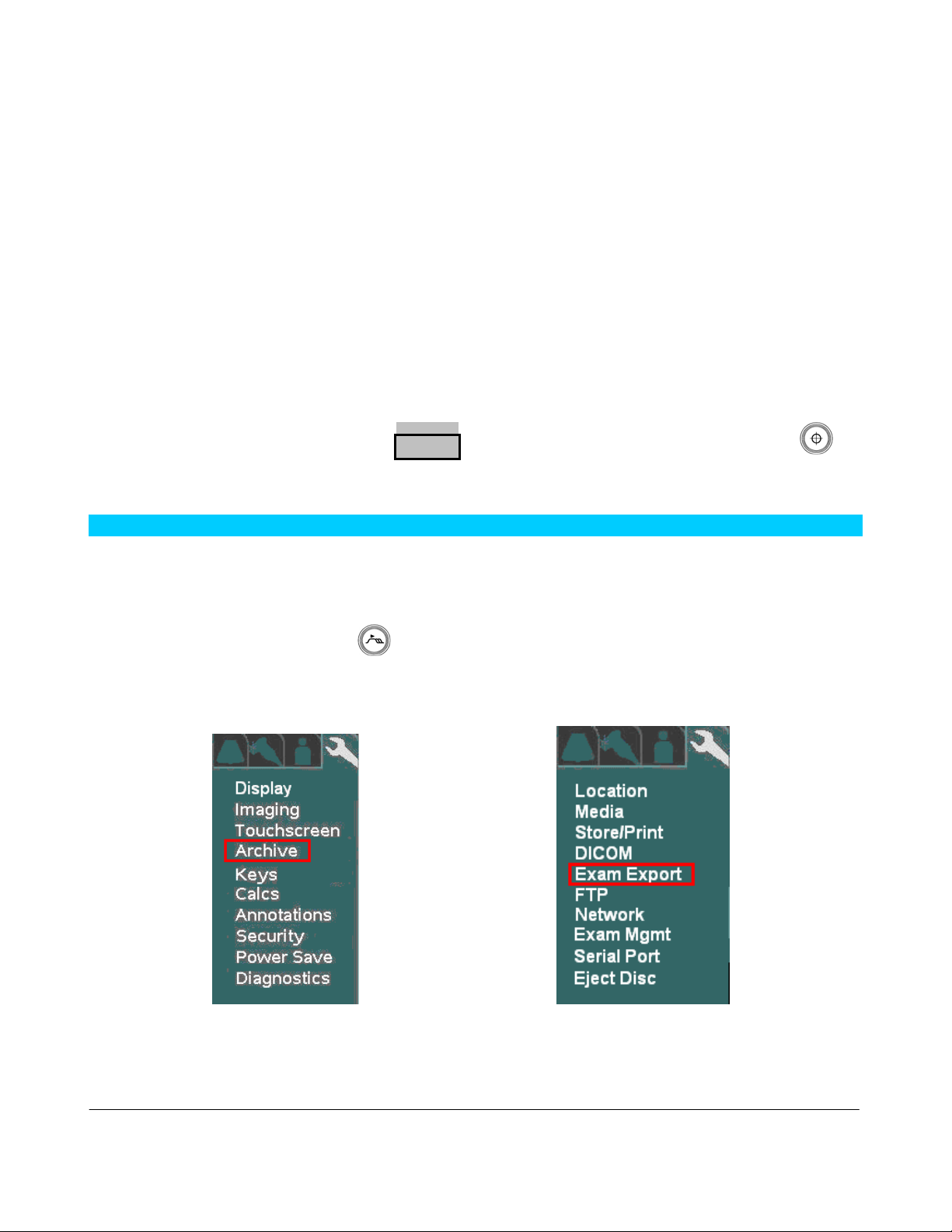
Screenshot If checked, the entire screen area (1280 x 1024), including the
dashboard and thumbnail area, is captured.
7. Configure the “Image Transfer Mode” selection to reflect the desired image transfer behavior
on the Customer’s system.
Exam in Progress: Results in each new DICOM image immediately being placed into the
DICOM Queue for transfer to the target network/print device, each
time the corresponding STORE/PRINT key is depressed.
Exam Completed: Images are buffered during each STORE key depression, and later
placed as a group into the DICOM Queue for network/print transfer.
The process for beginning the transfer of the images is automatically
started when the Operator ends the current exam.
8. Reports: If SR (Structured Report) sending was enabled on the Network Store page for any
PACS devices, select the desired target device in the pull-down menu.
9. To save the new settings, select APPLY from the main menu, and press the SET key to
save new settings.
7.2 “Exam Export” Menu
The EXAM EXPORT menu allows for configuring the formatting (Compression, Color Model, etc)
for images “Exported” to the target media device.
5. Using the page TAB button to advance menu screen to select TOOLS menu; then select
SYSTEM SETUP, then select ARCHIVE.
SYSTEM SETUP Menu ARCHIVE Menu
Q00169 Rev D Page 86 of 304
"Note: Copies are uncontrolled documents - For revision verification see the Master Docum e ntation List"
Page 87
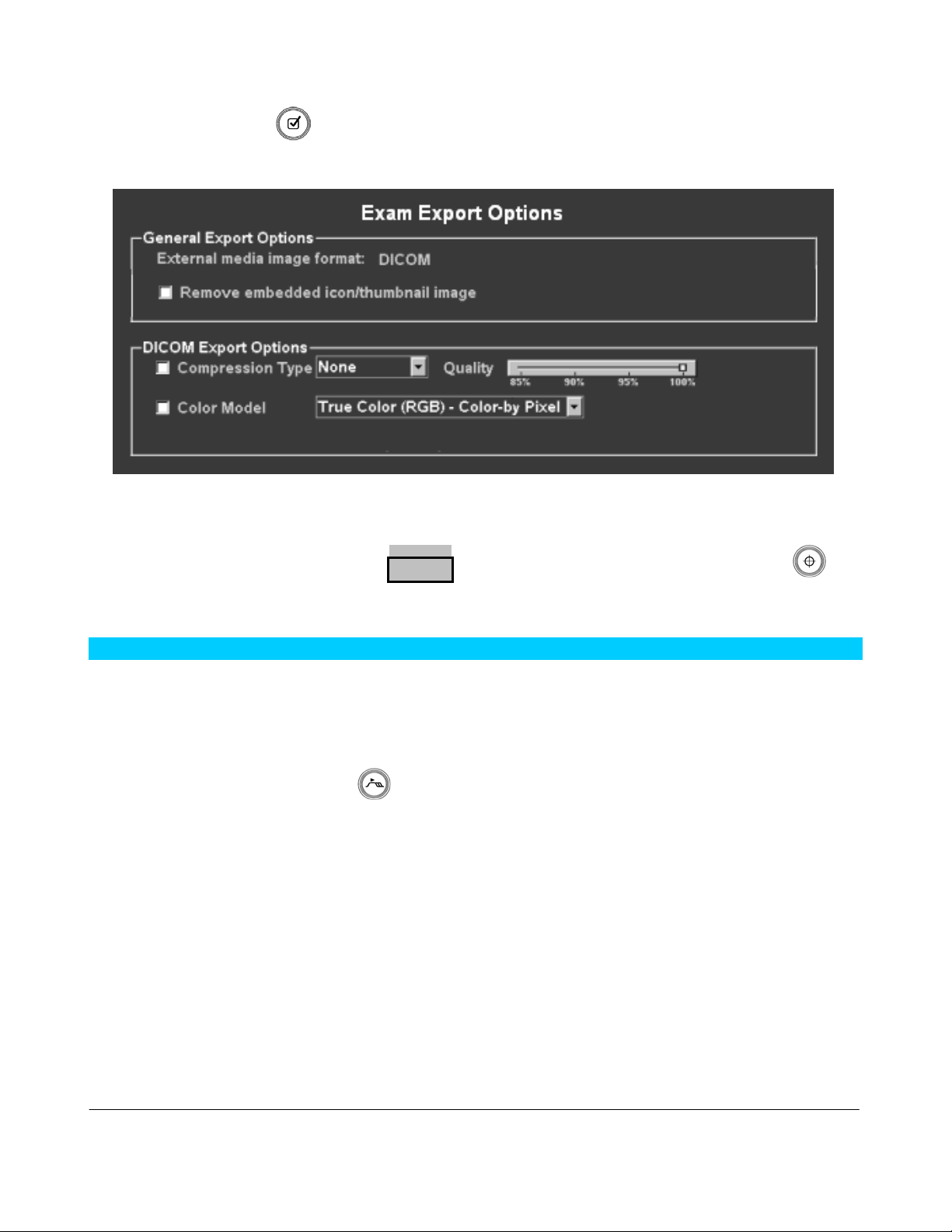
6. Using the Menu Control, arrow down to backlight EXAM EXPORT selection, and press the
SELECT button to bring up this menu.
EXAM EXPORT Sub-Menu
.
7. Configure the options settings to reflect the desired formatting for the target images upon
export.
8. To save the new settings, select APPLY from the main menu, and press the SET key to
save new settings.
7.3 “Exam Management” Menu
The EXAM MGMT menu allows for configuring the functionality of the system when “Restarting”
exams, and also provides access to low-level service functions for managing a variety of Archive
media.
1. Using the page TAB button
to advance menu screen to select TOOLS menu; then select
SYSTEM SETUP, then select ARCHIVE.
SYSTEM SETUP Menu ARCHIVE Menu
Q00169 Rev D Page 87 of 304
"Note: Copies are uncontrolled documents - For revision verification see the Master Docum e ntation List"
Page 88
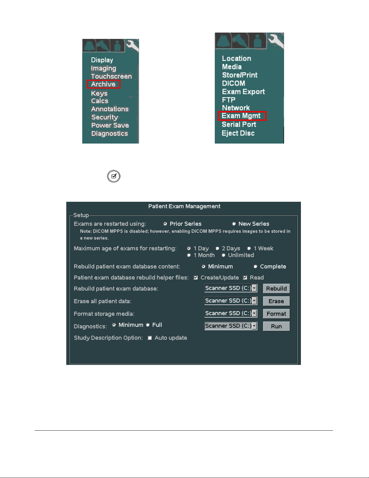
2. Using the Menu Control, arrow down to backlight EXAM MGT selection, and press the
SELECT button to bring up this menu.
EXAM MGMT Sub-Menu
.
3. Configure the “Exams Restarted Using” selection to reflect the desired grouping of images
upon restarting of a previous exam on the Customer’s system.
Prior Series: Appends new images onto the series of images previously captured.
Q00169 Rev D Page 88 of 304
"Note: Copies are uncontrolled documents - For revision verification see the Master Docum e ntation List"
Page 89

IMPORTANT
“Prior Series” selection is NOT available (“New Series” only) if the system has an active
DICOM MPPS server enabled on the DICOM MPPS configuration page.
New Series: Creates a new series of images, utilizing only the Patient info from the
earlier exam series.
4. Configure how many days prior to the current date that the Users will be allowed to
“RESTART” (add/delete images) internally Archived patient exams.
5. Select the granularity desired when initiating patient exam database rebuild operations.
6. Using the Menu Control, arrow down to backlight Apply selection in the main menu, and
press the SELECT button to save any exam “RESTART” configuration setup changes,
and exit
--------------------------------------------------------------------------------------------------------------------------
ARCHIVE SERVICE FUNCTIONS:
WARNING
Due to the deletion of the original (assumed corrupted) database file during the “REBUILD
PATIENT EXAM DATABASE” process, it should be noted that Patient information updates
made to initially started exams (i.e. changing Patient name info, etc, after the first image for a
study has already been stored) will only be retained in post-rebuilt exam, if the “READ” option
for the Helper files is “unchecked”.
Rebuild Patient Exam Database - Content:
This option allows for specifying the granularity of the exam database rebuild process that is
initiated with the “REBUILD” menu selection below.
NOTE: The exam database content granularity selections (described below) does not have
any effect (is not applicable) for rebuilds where the targeted device (via the pulldown selection) is an “External” media (i.e. USB memory sticks, CD/DVD, etc)
device.
Minimum: Rebuilds the study/exam table ONLY. Additional rebuilding, of the other
tables, will occur later, as each individual study is accessed. (fastest)
Complete: Completely rebuilds all
exam database tables, including exam/study
table, series table, image/IQ/key image note table. (longer)
Patient Exam Database Rebuild “Helper” Files:
These settings allows for specifying how the database “Helper” files will be affected/utilized,
when the “REBUILD” operation is performed.
NOTE: Default is both boxes selected (“checked”):
Q00169 Rev D Page 89 of 304
"Note: Copies are uncontrolled documents - For revision verification see the Master Docum e ntation List"
Page 90

Read: When checked: Tells the system to look for (read) the existence of a
valid single “HELPER” file (most current patient/exam information
for entire study) for each exam, and use its content exclusively for the
database rebuild operation (fastest)
When unchecked: The system will scan all files in each exam folder,
looking for the most current data to be used for creation/update of the
“HELPER” file. (longer)
Create/Update: When checked: Instructs the system to generate a current
“HELPER” file for each exam, during the execution of the “Rebuild”
process. Once completed, subsequent “Rebuilds” should run much
more quickly (as long as the “READ” option box is also checked)
When unchecked: The system will not create or make any updates to
existing “HELPER” files, when the “Rebuild” operation is performed.
Rebuild Patient Exam Database:
Clicking on this menu item begins the database “Rebuild” process. The “Rebuild” process is
intended to be used in cases where exam access to the patient image ARCHIVE of the internal
exam storage of the scan engine, or other archive media (Cart Hard Drive, remote USB media,
CD/DVD, etc) becomes problematic.
Selecting the “REBUILD” box will regenerate the database’s index file (directory) and
potentially resolve the problem. Select the desired media device, using the provided pull-down
menu, prior to initiating the “Rebuild” process.
--------------------------------------------------------------------------------------------------------------------------
Erase All Patient Data:
WARNING
Initiating the “ERASE” function will completely delete ALL patient exams (all stored images)
on the internal ARCHIVE storage of the Scan Engine. DO NOT perform this function
the system’s User has confirmed that all needed exams/images have been exported/transferred
to another medium, or are no longer needed.
Due to this operation performing individual “deletes”, the “ERASE” operation may take an
extended period of time to complete if the selected Archive media contains an extensive number
of patient exams.
unless
In extreme cases where the system is totally unable to access the ARCHIVE on either the scan
engine or other media (HDD in Cart, etc), selecting the “ERASE” function will completely
clear (erase) the following:
All stored patient exams (images)
All patient exams pending DICOM transfer in DICOM QUEUE (if C drive selected)
Q00169 Rev D Page 90 of 304
"Note: Copies are uncontrolled documents - For revision verification see the Master Docum e ntation List"
Page 91

Select the desire media device using the provided pull-down menu.
--------------------------------------------------------------------------------------------------------------------------
Format Storage Media:
NOTICE
Initiating the “FORMAT” function will result in removing ALL of the contents of the target
media device. This includes the following IF the “C” drive (Scan Engine/Scan Module internal
storage) is selected:
Patient exams
System Logs
DICOM Queue jobs
Some Transducer file
To prevent Users from accidentally performing this operation a “Service Password” prompt will
appear prior to this “FORMAT” operation activating. Contact Zonare Technical Support in order to
obtain the service password and assistance on this operation.
Due to the erasing of some transducer files, reloading of system software will be required after
performing this “FORMAT” operation.
In extreme cases where the system is totally unable to access the internal storage media of the
scan engine (“C” drive) or other media (HDD in Cart, etc), selecting the “FORMAT” function
will completely reformat the media; erasing all contents. Due to the operation being a
complete” FORMAT” where no individual files are accessed, it is completed very quickly.
Select the desire media device using the provided pull-down menu.
--------------------------------------------------------------------------------------------------------------------------
Diagnostics:
The diagnostic function provides the ability to perform a database screening of the selected
archive media device to verify its integrity. The media devices available for diagnostic testing
are:
Scanner SSD (C:) – Scanner Internal Archive Media
Cart HDD (F:) – SmartCart Hard Drive
Two different options are offered to define the granularity level of the diagnostic testing.
Minimum: ..................Basic level diagnostic screening of target media device (quick)
Full:.............................Comprehensive screening of target media device (longer)
--------------------------------------------------------------------------------------------------------------------------
Study Description Option:
Auto Update
Q00169 Rev D Page 91 of 304
"Note: Copies are uncontrolled documents - For revision verification see the Master Docum e ntation List"
Page 92

The “Auto Update” option being selected results in the “Study Description” field (DICOM
Tag: 0008,1030), on the Patient Demographics page, being automatically populated with
source information provided from the DICOM Worklist server (if info is provided).
If no auto-populated source information is provided for this field (or this box is unchecked),
the information can be manually entered by the User on the Patient Demographic page.
Q00169 Rev D Page 92 of 304
"Note: Copies are uncontrolled documents - For revision verification see the Master Docum e ntation List"
Page 93

7.4 Archive “Export” – OPTION menu
The EXPORT function on the ARCHIVE page includes a special OPTIONS page. This page allows
for customizing the steps that will be performed, and the data formatting, that will occur during the
export. The export options are as shown in the menu below:
--------------------------------------------------------------------------------------------------------------------------
General Export Options
External Media Image Format:
DICOM: Exam data stored on output device in native DICOM format (may be re-
imported later).
Non-DICOM: Exam data stored on output target device in a non-DICOM (cannot be re-
imported or viewed on Zonare) format, as selected in non-DICOM export
option area.
Hard Drive Verify Options:
Minimum: Basic level checksum verification only (fastest)
Maximum: Full filesystem data verification (longest)
CD/DVD Verify Options:
Q00169 Rev D Page 93 of 304
"Note: Copies are uncontrolled documents - For revision verification see the Master Docum e ntation List"
Page 94

On: Comprehensive data validation operation at end of data export (longest)
Off: No advanced data validation, but basic data checking still performed (fastest)
Remove embedded icon/thumbnail image:
When checked, the small icon/thumbnail images will be removed from all images
Remove Identity of Patients:
Assign a unique patient identity to each exam (DCOM only):
Assign a common patient identity to each exam (DCOM only):
--------------------------------------------------------------------------------------------------------------------------
DICOM Export Options
Compression Type:
Pull-down menu selection of different data compression (file size reduction) options
Color Model:
Pull-down menu selection of different option for color mapping data format
--------------------------------------------------------------------------------------------------------------------------
Non-DICOM Export Options
Still Image File Format Type:
JPEG: Saves images as JPEG standard computer format
TIFF: Saves images as TIFF standard computer format
Include Patient Name in Export Folder:
When checked, the export folder naming convention will include patient name
ZIP Exported Exam Folders:
When checked, WINZIP compression of the final exam folder will be performed:
Q00169 Rev D Page 94 of 304
"Note: Copies are uncontrolled documents - For revision verification see the Master Docum e ntation List"
Page 95
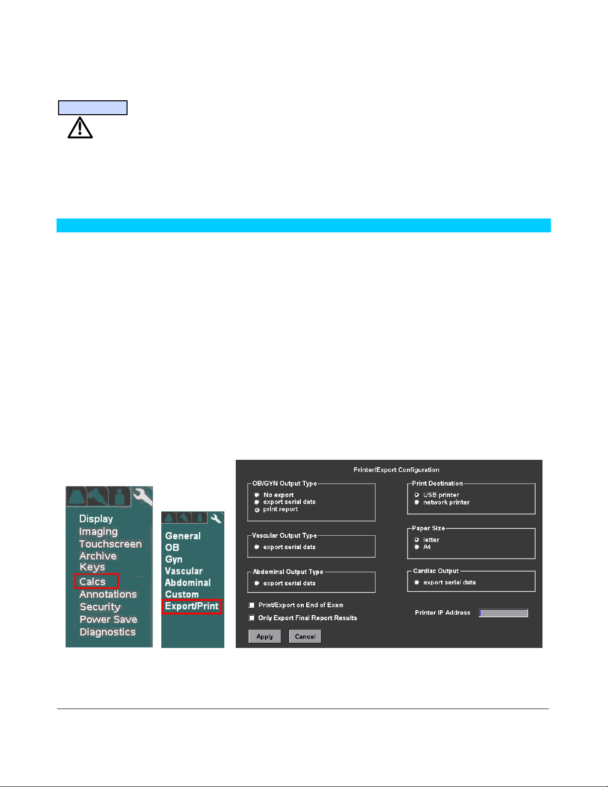
In extreme cases where the system is totally unable to access the ARCHIVE on either the scan
engine or other media (HDD in Cart, etc), selecting the “ERASE” function will completely
clear (erase) the following:
IMPORTANT
For use of DVD media type for Exports, only one brand/model of DVD media has been tested
and approved to be compatible for use in the Zonare system. The approved DVD media type is
as listed below:
- Taiyo Yuden brand DVD media ONLY!
7.5 “Serial Port” Setup - (Export Calc Report Data)
The SERIAL PORT configuration menu allows for configuring the system to be able to “EXPORT”
report data to 3rd-Party external report generator equipment, via a “USB” port connection on the
Z.ONEUltra product (miniCart/SmartCart).
The three (3) types of Calc report data that can be exported, via the USB port (on a
miniCart/SmartCart), are as listed below. Configuring which report type(s) will be exported is
performed on the SYSTEM SETUP ->CALCS -> EXPORT/PRINT menu.
OB/GYN Calc Output
VASCULAR Calc Output
CARDIAC Calc Data
System Setup -> Calc -> Export/Print
Q00169 Rev D Page 95 of 304
"Note: Copies are uncontrolled documents - For revision verification see the Master Docum e ntation List"
Page 96

1. Using the page TAB button to advance menu screen to select TOOLS menu; then select
SYSTEM SETUP, then select ARCHIVE.
SYSTEM SETUP Menu ARCHIVE Menu
2. Using the Menu Control, arrow down to backlight SERIAL PORT selection, and press the
SELECT button to bring up this menu.
NOTE: The serial “Port A” and “Port B” selections, and all of the serial port setting selections
(Bits per second, Parity, etc) in the menu are NOT applicable on the Z.ONEUltra
products (miniCart/SmartCart). They appear only as a historical function to support the
previous generation “SuperCart” product.
SERIAL PORT Sub-Menu
3. If desired, check the box to select the USB port as the target for EXPORT function of
OB/GYN report data.
Q00169 Rev D Page 96 of 304
"Note: Copies are uncontrolled documents - For revision verification see the Master Docum e ntation List"
Page 97

4. If desired for report data to be exported in sync with DICOM image transfers to the PACS
system over the network, check the box for “Link Serial Connect to Ethernet Connect”.
5. Using the Menu Control, arrow down to backlight Apply selection in the main menu, and
press the SELECT button to save the serial port configuration setup, and exit
Q00169 Rev D Page 97 of 304
"Note: Copies are uncontrolled documents - For revision verification see the Master Docum e ntation List"
Page 98

8 DICOM CONFIGURATION
8.1 “DICOM” Configuration Overview
Prior to installation of the Z.ONEUltra at any medical facility utilizing a DICOM network
environment, a “Pre-Install Survey Form” (ZONARE P/N: F00044) should have been completed.
This form is used for obtaining, in advance, detailed networking and DICOM configuration values (IP
addresses, AE Titles, etc.) from the IT/PACS System Administrator at the facility. These site-specific
values/parameters are required prior to programming the entries in the DICOM configuration menus
on the Z.ONEUltra.
A copy of this “Pre-Install Survey Form” is included on the following pages, as a backup resource.
IMPORTANT
Once all of the DICOM parameters have been configured into the required DICOM
setup menus, it will be necessary to power down and reboot the Z.ONEUltra in order to
initialize the new network connections with the target devices.
Z.ONE Network Address Info Requirements:
The following information, defining the Z.ONEUltra’s identity on the local network at the
medical facility and must be assigned by the facility’s IT/PACS Network Administrator, prior to
beginning the setup of the DICOM configuration menus on the Z.ONEUltra.
Definition
Assigned Value Example Only
Z.ONEUltra (IP Address): _ _ _ . _ _ _ . _ _ _ . _ _ _ 10.94.1.105
Z.ONEUltra (Gateway Address): _ _ _ . _ _ _ . _ _ _ . _ _ _ 10.94.1.1
Z.ONEUltra (Subnet Mask): _ _ _ . _ _ _ . _ _ _ . _ _ _ 255.255.255.0
Q00169 Rev D Page 98 of 304
"Note: Copies are uncontrolled documents - For revision verification see the Master Docum e ntation List"
Page 99

8.2 “DICOM” Configuration Parameter Definitions:
The table below provides some guidance regarding the type of information required for the DICOM
configuration of the various menus (“General”, “Printers”, Network Store”, “MPPS” and
“Worklist”) on the Z.ONEUltra.
DICOM Configuration Parameters: Definition:
AE Title
e.g., “Zonare1”
Association Acceptor Configuration options to enable cases where the Z.ONE is desired to be
Color Model
Compression
None
RLE Lossle ss
JPEG Lossy
Date Range
The official “name” (Application Entity) assigned to
network administrator) to identify it to the network.
configured to serve as a DICOM host for accepting DICOM association requests
and store requests from other DICOM devices
Defines the method that will be used (Grayscale, RGB color, etc.) by the
receiving device (DICOM PACS system) for interpreting the different bit level
values of the data, within the transferred images
Selections include:
- Palette Color
- True Color (RGB) - Color by Pixel
- True Color (RGB) - Color by Plane
- Grayscale (Monochrome2)
Enables the ability to compress image files for the purpose of reducing file size
and transfer times.
RLE Lossless automatically reduces the size of the transferred image, yet retains
all source content.
Provide the highest level of image file size reduction (compression) of all the
options. User selectable “Quality” setting (between 85-100%) determines
resultant file size.
Specify the number of days back (Today, 2, 7, All) that the DICOM worklist will
reference scheduled examinations.
the Z.ONEUltra (by the
Gateway IP Address A designated TCP/IP address (i.e 10.1.1.254) that is required in cases where the
Z.ONEUltra is to be connected to target devices that are outside the primary
host network (FTP remote access, for example).
ICON Image
IP address
Keep Alive Timeout
Key Image Note/Key Object Selection
Document
Limit by Modality
None
Q00169 Rev D Page 99 of 304
"Note: Copies are uncontrolled documents - For revision verification see the Master Docum e ntation List"
A sub-sampled (miniature size) version of the image created for each patient
image on the
from DICOM image transfers to the target device. (default is “retain”)
Internet Protocol address. A unique Internet address for devices attached to an IP
network (TCP/IP network).
Specify the duration (in seconds) that an established DICOM connection will be
maintained, after completion of the last transfer.
Specifies the sending of Key Image Note electronic “Post-It” note info, as Key
Object Document content during the DICOM-DICOM SR transfers to the PACS
system.
Filtering by modality (US, CT, MRI, et cetera) of scheduled patient examination
data generated by the Worklist server. Set according to department requirements.
Z.ONEUltra. Options are to either retain or remove these images
Page 100

DICOM Configuration Parameters: Definition:
US (ultrasound)
50+ additional options:
(see list of selections)
Log Level
None: Show entries for all modalities.
US: Show entries for ultrasound exams only.
The following additional modality filter (limit) settings are available for selection:
Selections – AU, BI, CD, CR, CT, DD, DG, DX, ECG, EPS, ES, FID, GM, HC, HD,
IO, IVUA, KO, LS, MG, MR, NM, OP, OT, PR, PT, PX, REG, RF, RG, RTDOSE,
RTIMAGE, RTPLAN, RTRECORD, RWV, SM, SMR, SR, ST, TG, US, XA, XC
Defines the level of detail information that will be displayed in the DICOM
Queue.
Maximum entries cached
Enter a number between 0 and 999
Set according to department requirements. A higher number provides access to
more scheduled exams, but increases the time required to search for the exam of
interest.
Minimum/Maximum Film Density For defining Minimum/Maximum density of images on film. Value entered is
expressed in hundredths of OD (optical density). A value entered of 150,
corresponds with 1.5 OD. Typical acceptable values to be entered are 000-399,
with 020 (for “Min”) and 300 (for “Max”) being a potential starting point.
Network Type
Nickname
e.g., “Prep Room Printer”
Allows for manual or auto setup of network speed and duplex operational state.
Selections include: Auto-Negotiate, 100MB/Full-Duplex, 100MB/Half-Duplex,
10MB/Full-Duplex, 10MB/Half-Duplex
An informal name to identify the device to users in the department. This name is
typically assigned in the department.
Network Usage Type Defines the interval at which DICOM images will be transferred over the network
to the PACS storage device. Either immediately upon each press of STORE
(“Exam in Progress”), or at the termination of the current examination (“Exam
Completed”).
- Exam In Progress
- Exam Completed
No Color
If selected, images that are captured when the
modalities where no “Color” is present (B-Mode, PW Doppler, M-Mode), will be
Z.ONEUltra is being operated in
transferred to the receiving DICOM device (Network Store system) as
“Grayscale-Monochrome2.
Despite this “No Color” selection being active, all images captured while in Color
Doppler mode will still be transferred to PACS using the color map selected in
the Color Model field.
PDU Receive/Send Size
The size (in bytes) of the basic data packets (PDU: Process Data Unit) that will be
trasferred during receive and transmit operations. (default is 16384 = 16K)
Pixel Spacing Adds ability to assign CT/MR-specific pixel spacing to ultrasound images sent to
PACS, to allow for calibrating pixels to millimeters for measurements.
Polling Interval (minutes)
None
The frequency of automatic updates to the worklist. A short polling interval may
impact system performance. Choose a preferred interval; or choose None to
update the worklist only on demand.
choose minutes
Port number The TCP/IP port number that is being used by the DICOM device connected to
the Z.ONEUltra. Default port value is 104.
Queue Timeout (sec)
Queue Start Type
The maximum amount of time that a DICOM job will remain active in the queue,
before it times out.
Defines whether the start of jobs in the DICOM queue will be performed
automatically or started manually.
Q00169 Rev D Page 100 of 304
"Note: Copies are uncontrolled documents - For revision verification see the Master Docum e ntation List"
 Loading...