

Page 1
I
-------
•
HIGH
~
SPEED
R.
INTERLOCK
SEWING
- -
*JlzJ-Eoo?
MACHINE
iE
5I
OPERATION MANUAL
PARTS
m
ijt
iq:
ttl
Iii·
ttl
ZOJE
SEWING
aJJ
=¥-
BOOK
lllil
m
=K
I}
iliR
R~
MACHINE
fR
fSi
CO
Bll
~
.. L TO.
61
Page 2

(
..
*~ffl~~~~~#~ffl~W.
The description covered
commodity without notice.
~7~~~HB~~~~~~.
in
this operation manual and parts book
- I -
-~-~m.
is
subject to change for improvement of the
Page 3
1
General Safety lnstrutions
Warning I When using this machine, basic safety precautions should always be followed to reduce the
risk
of
fire, electric shock and personal injury, including the following.
Read all these instructions before operating this product and save these Instructions.
1. Keep work area clean.
Cluttered areas and benches invite injuries.
2. Consider work area ,environment.
Do
not expose power to rain. Do not use machine tools
well lit. Dot not use power tools where there is risk to cause fire
in
damp
or
wet locations, Keep work area
or
explosion.
3. Guard against electric shock.
Avoid baby contact with earthed or grounded surfaces (e.g.pipes, radiators, ranges refrigerators).
4. Keep children away
Do
not
let visitors touch the tool
or
extension code .
5. Dress properly.
Do not wear loose clothing or jewelry, they can be caught In moving parts. Wear protecting hair
corering
to
contain long hair.
6. Do not abuse the cord.
Never carry the machine by cord
or
yank it to disconnect it from the socket, Keep the cord away
from heat, oil and sharp edges.
7. Maintain machine with care.
Follow instructions for lubrication and changing accessories. Inspect tool cord periodically and if
damaged have it repaired by an authorized serviced facility.
8.
Disconnect machine
When not in use, before servicing and when changing accessories.
9. Avoid unintentional starting.
Do
not
carry a plugged • in tool with a finger on the switch. Ensure switch is off when plugging in.
10. Check damaged parts.
Before further use
determine that it
11
. Warning.
The use of any accessory or attachment, other than those recommended
of
the tool. a guard or other part that is damaged should be carefully checked to
will operate properly and perform its intended function.
in
this instruction manual,
may present a risk of personal injury.
12. Have your
tool repaired by qualified person.
Repairs should only be carried out by qualified persons using original spare parts.
Special Waning For Electric Connection !
1.1ncorporate this machine only with "CE" certificate hold
1 2.Follow the instruction manual device to install controc device.
-to-
3.Aiways earth machine appropriately during operation.
: 4.Before adjustment, parts change
or
servicing must be sure to pull out the plug from socket to prevent
hazard of unintentionally start of machine.
-
1l
-
run control device.
the
Page 4
~~
INSTALLATION
f?l~~&:m
~m
ii!JiJ~jm£~
i~Jjmft£~
mn~~;IHt-J~~~~m
Mit£~
~~JJ5t
ffi~f'A~JlWa:lf!
it~~~~~Wa:lf!
n~~H~~ffiJU&
:
_t)Z~~~~ifajfl
MOTOR AND BELT
LUBRICATION
HOW
TO
CHANGE OIL
HOW
TO
CHANGE OIL FILTER
LUBRICATE AND THE COOLING OF NEEDLES AND THREADS
TO REPLACE NEEDLES
THREADING
ADJUSTING THREAD TENSION
ADJUSTING
ADJUSTING NEEDLE THREAD TAKE-UP
ADJUSTING SPREADER THREAD TAKE-UP
NEEDLE
THREAD
TAKE-UP
1
2
2
2
3
3
4
4
4
4
4
I
iffillf!JWa:lf!
:~~*llWa:lf!
~f;l:rttWa:lfl
ffillf!J
ffi
:n
~m
Jt
ifaJ
•
~~Ill
~*&Ill
-~~~$19ii.~P_ij
nil~i**
Wi*lll
ADJUSTING PRESSER FOOT
ADJUSTING STITCH LENGTH
ADJUSTING DIFFERENTIAL FEED RATIO
ADJUSTING THE PRESSURE OF PRESSER FOOT
THREADING DIAGRAM
TABLE CUT-OUT
IMPORT SAFETY INSTRUCTION
CONVERSION CHART
PARTS LIST
-m-
5
5
6
6
7
7
10
11
15
Page 5
INSTALLATION
I
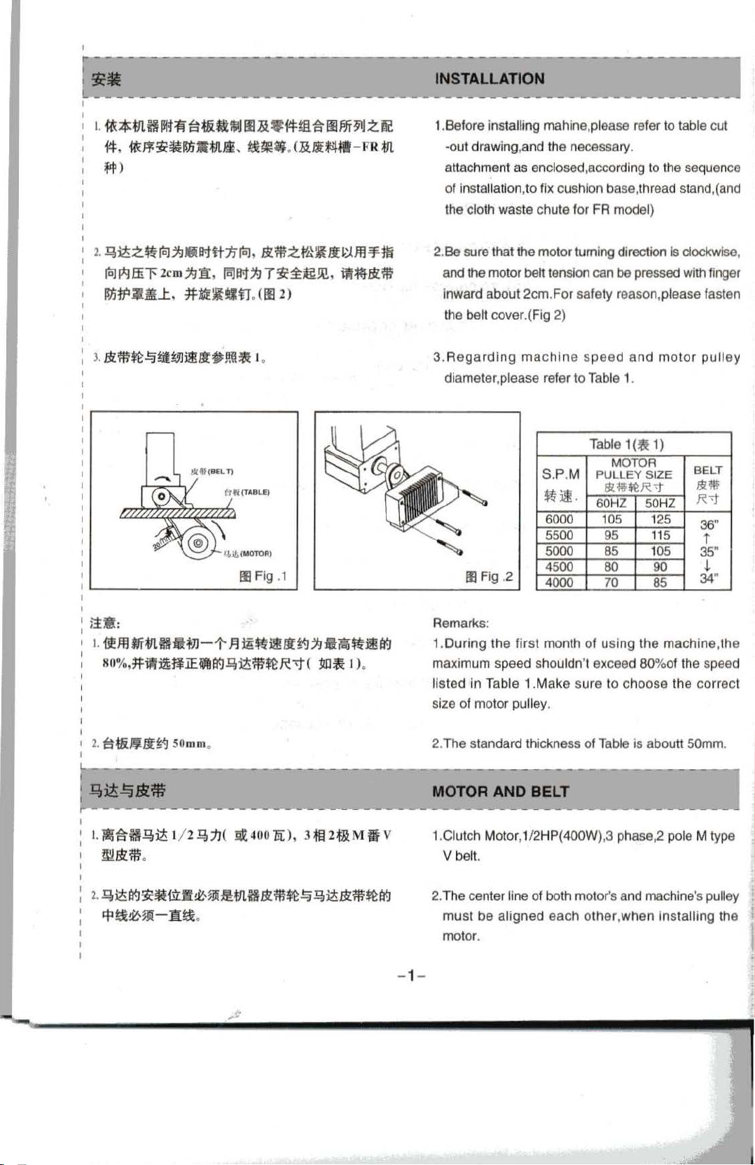
1.
***'Li§IJIH:f~t&ti$JJIII».9#~:~11l~Jf91J.ZIC
#,
it<F¥~~!~Mti
*
JL.Ii,
t£~-.(».Jl~M
- FR*'l,
:fit!)
L
~~.z•~~DMH~~.amz•~~~m~~
~~.ffil'2cm~1i:.
~#'ll.&l..t,
FcJM~7~i:~m,
#t't~*ltf
.
(lll2)
ii~.Bl*
Ill Fig .1
1.Before installing mahine,please refer to table cut
-out drawing,and the necessary.
achme
att
of
the cloth waste chute
Be
2.
and the motor
inward
the belt cover.(Fig 2}
3.Aegarding
diameter,please refer to Table 1.
nt as enclosed,according to the sequence
installation,to fix cushion base, thread stand,(and
for
FA
model)
sure that the
about
Ill Fig .2
motor
turning direction is clockwise,
belt tension can be pressed with finger
2cm.For
machine
safety reason,please fasten
speed
Table
S.P.M PULLEY SIZE
~
~.
6000 1
5500
5000
4500 80 90
4000 70 85
MOTOR
8l'$~R
60HZ 50HZ
05
95
85
and
1(~
1}
-t
125
115
105
motor
pulley
BELT
8l~
R-t
36"
i
35"
J.
34"
ita:
1.
i!ml!f*'l.fi:&HJJ-1'
8 0
%,#fl!i~~.iE
Flm.imll;~~-~-i!~
iiJA
~~it£m~R'i"(
jm~
I ).
Remarks:
1.During
maximum
isted
l
size
2.
The
MOTOR
t.
11J~H!?Jit£
l/2Q,1J(
Sit
40
0
a),
HIUfi
M
if
v
1.Ciutch Motor, 1/2 HP(400W},3 phase,2 pole M type
v belt.
~
· *
·
I
2.
~~~~Ett-ut.i!~~l£ma•m~~~~•*~~
'*'~~~-1!~
.
2.The center line
must
motor.
- 1-
.....
the
first
month
speed
shouldn't exceed 80%
in
Table
1 .Make
of
motor pulley.
standard thickness
AND
BELT
of both motor's and machine's pulley
be
aligned
each
of
using
the
machine,the
of
sure
to ch
oose the
of
Table is abouttSOmm.
other,when
installing
the speed
correct
the
Page 6
t--
--
- -
~~--
:
]I!)~
L----
I
1
1.
2.
l·~~~Ma,
----
~mm
MOBIL
a:J-T$JTfJLi§1£~iEHtre:m;m1J!J~.
i~Jf.liitr~'~9i)t)\.$Jf)fb
.Ami§~,
(003,
~~hi!M~.
~9!
m
ffl~fi•~~•mffl..t~~z~•~
4)
1-
~
;~
*
-
----
---
- -
--
----------
LUBRICATION
-
~------
#1o~Esso
.
~-~e~-r~•mfflWZ~~.
~mH1fMiE~.~Jf.liitr,Ma~
ttt
~
i!f
~
-
-
--------
#32~fc.lt&tf.l~;~;m
~llt$JT*'l.H1£
~1f
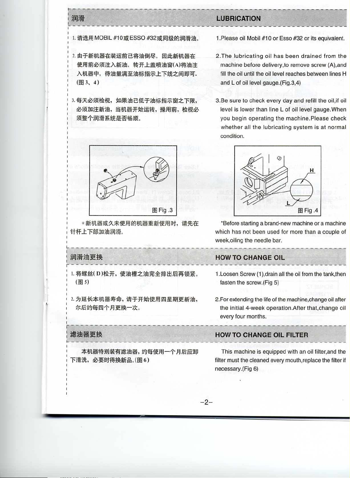
..t~I!Mifb'fi!(A)~~)fb;!
J
IID!
.
---___
.
Please oil Mobil
1.
2.
The
machine before
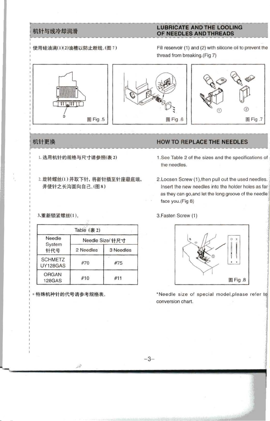
fill the oil until the oil level reaches between lines H
and L of oil level gauge.(Fig.3,4)
3.Be sure
level is lower than line L
you begin operating
whether
condition.
-
----~---
.,._
- -
---
lubricating
-----~~---~
_.._
---
-
--
---"""-
#1 0 or
Esso #32
oil
has
been
delivery,to remove screw (A).and
to
check every day and refill the oil,if oil
of
the
machine.Piease check
all
the
lubricating
--
~----
or
its equivalent.
drained
oil level gauge. When
system
from the
is
at
normal
-
IE
Fig .3
*Before starting a brand-new machine
which has not been used for more than a
I
L--
-----------------
1
'~m~m£
I
r---
1.
~~~~(
(Ill 5)
1 2.
7.1l!f***JLH~'tri.
mFotf.J•rm-t
I
I
,------------~-------------
:
~5WHI!~
~----------------------------------------------------------
~
-----------------
o
Wa1f,
i~1m~:Zifb:fe~~Hl:iJ§Jit!i!~
iwr1fMf~mrm~WBl!Mim
.F.I
£~-1x
.
------
---
----------------------------
--
.
,
--
week,oiling the needle bar.
-------------------------------
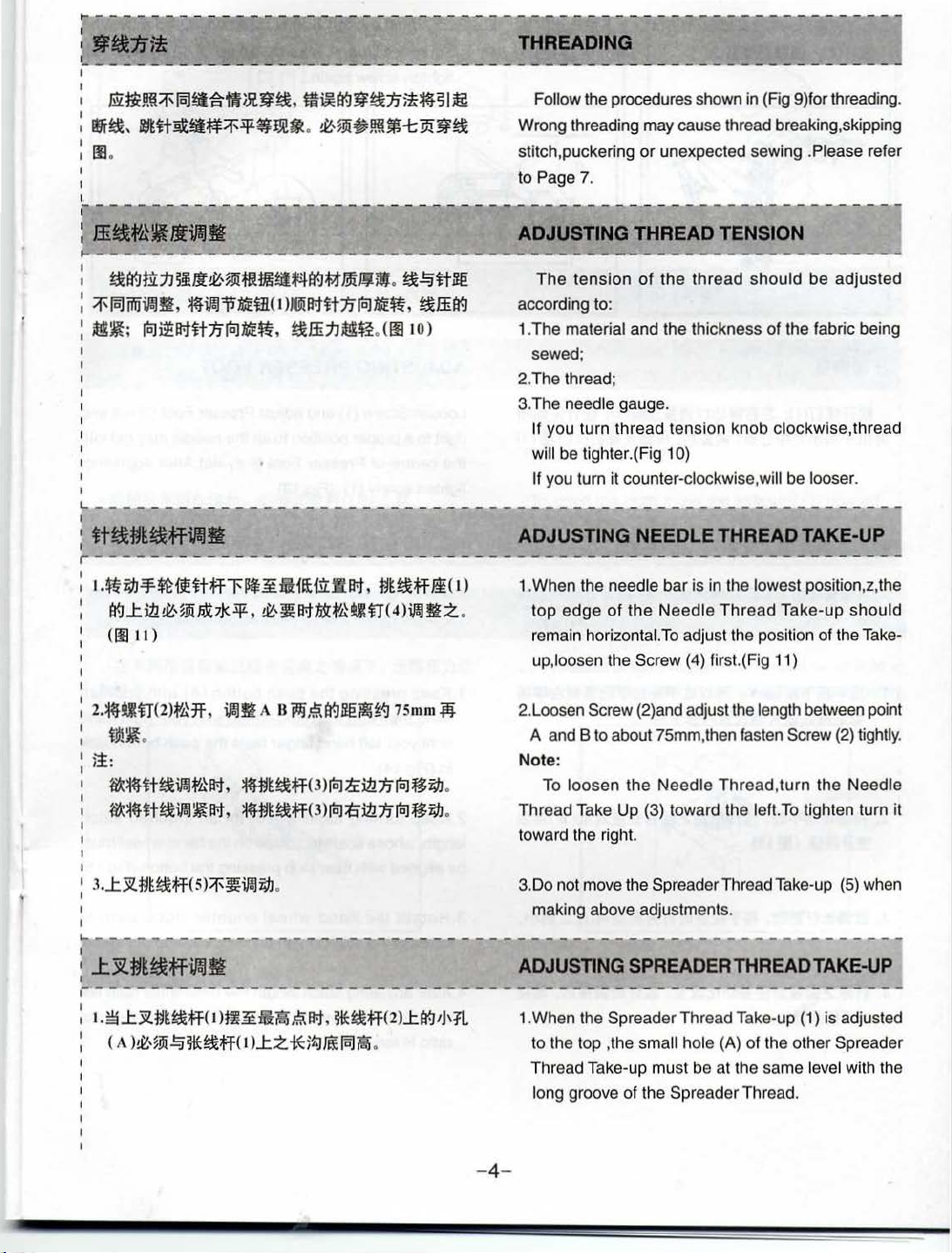
HOW TO CHANGE
1.Loosen Screw
fasten the screw.(Fig
2.For extending the life of the machine,change oil after
the
initial 4-week operation.After that,change oil
every four months.
-------------------~----------
HOW TO CHANGE OIL FILTER
This machine is equipped with an oil filter,and the
filter must the cleaned every mouth,replace the filter
necessary.(Fig
6)
OIL
(1
),drain all the oil from the tank, then
5)
00
Fig
.4
or
a machine
couple of
-
------
if
-
2-
Page 7
LUBRICATE
OF
NEEDLES
AND
AND
THE
LOOLING
THREADS
~~-------------~
Fill reservoir (1) and (2) with silicone
thread from breaking.(Fig 7)
oil
to
prevent the
0
2.
1Jff~~~(
*~ttz.-!(:i1iJWia:J~2
t > *~l'tt,
Ill Fig .5
~f!f~Hai.~ttl.iS!if~lftt.
ems>
..
Table
c•2>
Needle
System
ttft~
SCHMETZ
UY128GAS
Ne
edle Size/
2 Needles
#70
ft
R \j"
3 Needles
#75
Ill Fig .6
HOW
TO
REPLACE
1.See Table 2
the needles.
2.Loosen
Insert the new needles into the holder holes as tar
as they can go,and let the long groove of the needle.
face you.(Fig 8)
3.Fasten
of
Screw
Screw (1)
THE NEEDLES
the sizes and the specifications of
(1
),then pull out the used needles.
Ill Fig .7
ORGAN
128GAS
#10
#11
•Needle
conversion chart.
-3
-
size
of
special
model,
Ill Fig .8
please
refer
to'
Page 8
THREADING
--
---
-
·--.,-..,.,
mz~mt:if'
:
~fi,~~~~~:if'~~~-
I
I
lll
o
I
r-
- -
t
.ffi
~f~
fitr.Jm:tJ~~Jl~,~~mtitit*4tr.J~mJ¥il
:if'
15.1
~~;
}-----
:
ttt&~~iiUf\'IJfi
r-
--
t
.~~-=f.$tuHtffl'llf~iiiH£til:.WR1,
tr.Jl:ill
(IIIII)
15.1~~m~R~r&.
.....
- -
-----
- - - - -
JJtlJIJ!i
,
__
~-~-
iiU
ilalllt
' ~
iJW11
14£
lol~R1~1Jiolt4E~,
- --..- -
- -
uH~IiX*-¥,
-,---
---------~----------------~---~--------------~~--
m~tr.J~r&:nit~sl
.
~~~Jm~~~~fi
----
- ---- -
il
( I )
J@i
R1
~t
:n
loJ
~.ffi:tJ~G
--..----- ----
~,~R1~t'a~n<
~
.
~~~8€
ME~'
~
.ffi
tr.J
. (IiltO)
-...-~------
t1t~ff/i(
4)ilal
~z
t
)
.
Follow the procedures shown
Wrong threading may cause thread breaking,skipping
stitch,puckering
to Page 7.
ADJUSTING
The
tension
according to:
1.The
material and the thickness
sewed;
2.The thread;
3.The
needle gauge.
If you turn thread tension knob clockwise,thread
will be tighter.(Fig 1 0)
If
you turn it counter-clockwise, will be looser.
-
ADJUSTING
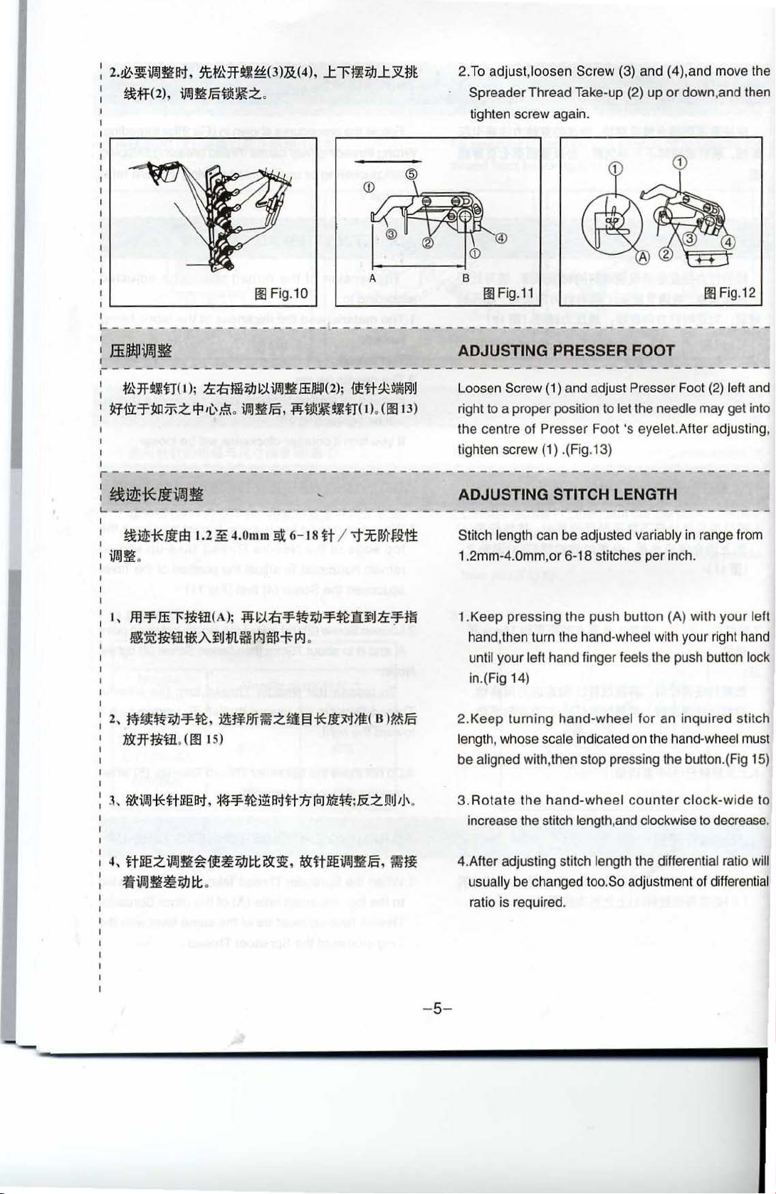
1.When the needle bar is in the lowest position,z,the
top
edge
remain horizontal.
up,loosen
in
(Fig 9)for threading.
or
unexpected sewing .Please refer
THREAD
of
the
NEEDLE
of
the
Needle
To
the Screw (4) first.(Fig 11)
TENSION
thr
ead
should
of
the fabric being
THREAD
Thread
adjust the position of the Take-
Take-up
be
adjusted
TAKE-UP
should
2.~~~fl(2)¥Mf
t9i~
.
~:
W:
~~~fii/!Jt'4R1'
W:~H~ilal~R1,
~---------~-~-----------
I
:
_tjl,~
~t&ff~!f
.----------
t.~l:Jl.t1tfiff(t
<"
)~,~m~~iHJtff<
,
ilalfl
A 8
i'1L~tr.J~il~J.:J
!14t1tfiff(
!14t1tfiff(3)1oltiill1Jiol~~
___
.._---------
Hl~ni~.~R1,
nJ:
3)
loJ
*fiff(2)l:tr.J'J'~L
z*;Z1~15.1PcJ
75mm
lr:ill
:n
loJ
3
-----------------------------------------------
.
-
~
.fli
.
.
2.Loosen
A and 8
Note:
Thread Take Up (3) toward the lett.
toward the right.
3.Do not move the Spreader Thread Take-up (5) when
making above adjustments.
------~----------~------
ADJUSTING
1.When the Spreader Thread Take-up (1) is adjusted
to
Thread Take-up must be at the same
long groove of the Spreader Thread.
Screw (2)and adjust the length between point
to
about 75mm,then fasten Screw (2) tightly.
To
loosen
the
SPREADERTHREADTAKE.UP
th
e top ,the small hole (A)
-4-
Needle
Thread,turn
To
of
the other Spreader
the Needle
tighten turn it
-----
-------
level with the
Page 9
2.~'~iJ!.IgJt-t,
!&tf(2)
~H'LHH1~(3)&(4)
,
il!.lflJ§f.d!~Z.
.
,
J:.l't
li"W
..
t.YZ.~~
@
2.To
adjust
,loosen Screw (3) and (4),and move the
Spreader Thread Take-up {2)
tighten screw again.
up
or
down,and then
IE
Fig.10
1-
- - - - - - - - - - - - - - - - - -
A
-.-
- - - - - - - - - - - - - - - - - - - - - - - - - - - - - - - - - - - - - -
B
Ill Fig.11 Ill Fig.12
ADJUSTING PRESSER FOOT
r
----------------------
I f'kJHitf( I
I
~tlLT:lUJff-ZI=Pil,\,S
I
I
);
1.i:titmi"W~:J.
iJ!.IgffiJI!P(2);
o
ir.JJIJ§,
.jijf_tj!~~tf(I)
r----------------------------
:
~~¥:lfii!Jf!
~-------------------------------------------------------
!&~iflffij
il!.llt.
I,
ffl-'f.
5~nim~Ai~fll.HI*J$T-I*J
1.2
.3¥.
ffil'nit!(A);
4.0
rnm ~ 6-
.jij~:J.ti-'f.~fW-'f.~]lifJ1.i:-:f-m
18
.
HI
-------
iitt:R~IXJU
.
(IIJIJ)
-----------------------------
Loosen Screw (1) and adjust Presser Foot (2) left and
right to a proper position to
the centre of Presser Foot 's
tighten screw (1) .(Fig.13)
-- --
ADJUSTING STITCH LENGTH
i"1C~ftf2tt
Stitch length can be adjusted variably in range from
1.2mm-4.0mm,or 6-18 stitches
Keep
1.
hand, then turn th e hand-wheel with your right hand
until your left hand finger feels the push button lock
in.(Fig 14)
let the needle may get into
eyelet.After adjusting,
--------------------------
per
inch.
pressing
the push
butt
on (A) with your left
---
-~
--------~------------------------
2,
r,J~~zw-'¥~
:!Dr1fnit!. (Ill
4,
ttBezil!.lt~~ii~zwtt:~:;:.
f.Til!.lm~zwtl:
.
iiM~PJT~z~
I 5)
.
!§!
~ttBeil!.lmJ§,
ifJJt~lf£<
s
>
~J§
mtt
2.Keep
length, whose scale indicated on the hand-wheel must
be
3.
4.After adjusting stitch
turning
aligned with,then stop pressing the button.(Fig 15)
Rotate
increase the stitch
usually
ratio is required.
be changed too. So adjustment of differential
hand-wheel
the
hand-wheel
for an inquired stitch
counter
length,and clockwise to decrease.
length the differential ratio will
clock-wide
- 5-
to
--
Page 10

m Fig.13 m!Fig.14
Iii Fig.15
~-~-~---..-~-~-....
t
~id:Jit
~
r
(2),
~------~---~.---
~
~~-11
i.Palll
a
--~~-----
**113z~i;lJ~tRT
...tl'~i;fJRTiPalm
-
~~~~
-
----~---
;.;..
1
:o
.s
iPaliPal~lfi
.
<oo
t6 )
-·--~--~·-----------
---
1:1.3
-.
- - - -- -
~
..-.
--
--""'-~--..._
f'MUJ-Ht
-----
-
~~
-
~-w-~~,...-
----.
1
ADJUSTING DIFFERENTIAL FEED
RATIO
-
-~-......._
.
...__,._,_~~
The
differential Feed Ratio
adjustable from 1 :0.5 to 1:1.3 (Fig 16}
To
adjust the ratio,loosen the
indicator
*To
*To gather the
.,..._....
(1
)up or down.
stitch the cloth,move the indicator (1) upward;
cloth,move the indicator (1) upward;
- -
---------
ADJUSTING
PRESS~~
Pressure of the Presser Foot should be as light as
possible,so that cloth can
fO ___
OT
.....
- -
of
this
nut
----
THE
~--~~-~~-
PRESSURE
be
fed and sewed smoothly.
~---....-.-
machine is
(2),move the
-~-
OF
-
+
00
Fig.16
- 6-
Iii Fig.17
Page 11

•'
(li\
'r
/UNIT:MM
J!fr{jf".!
FFD
·J~
11
/M
2l /DIF
11'
O~tlf
L
JWl"l'l; -2 FERENCE: + 2
,
-
0
- 7-
Page 12

FOR
FR
l(lfM.
/UNIT:MM
Wftf
R
>t~~
/DIFFERENCE:
45
445
345
310
~
Jk_
+2
l!)
co
C\1
8
<D
c;:;
s-s
moo
60
0
0
0
C\1
I
I I
L--~-----------------------------------------------------
1
.t
I
FOR
FR
l(lfM.
/UNIT:MM
Wi1iR.
>t~~
/DIFFERENCE:+2
0
;:::
~
l!)
l!)
C\1
l!)
l!)
0
~
0
0
0
(\j
C'l
0
l!)
~
0
55
0
445
119
392
345
383
310
B-B
f{1Jiffi
119
60
-8-
55
0
Page 13

-----
-
---
--
--
t(it'L /UNIT:MM
--
------
--------
4-R20
480
------- -------------
L()
:g
0
,....
(')
I'
g
...
L()
,....
0
---
--
8-8
..
m
----
380
4~-
80
0•--+--
- -
-------
(/,-,-------------------
--
-----------
0
--
- '
-----
--------------
I
I
'
~
J0---..1---
I
~
- - I
--
--
---
c--
-
---
-
--
---
------
-
-------
_ _
____________
- -
-----
__ ______
__
- 9-
I
J
I
Page 14

1.
•.Mmf1=il!
<o,
ilm~.a=Jtittr.J~Iillil::t:!4fmB'E!~~t?,
Transportation
(1).The machine packed with two piece covers that
made of expanded
polystyrene to protect it.
2.
f£11=ff1=il!
(1), fJI.ft:i!'ilJlla1,
3.{1=il!~
fJL3=1'~1±"f.;j-=f
J.ii.ZJll~~ll:!4f:Jtll..t,
400C
~~..ttr.Ji.ffii.Jlif1=,
4.tfi!!f
i±.ulli~Wi!!f*'Fff-z~~ii•,
•.m~mi;IJfi~ffi'.
~11-~..t~t?~w,
(2).Put the machine into
(3).Use a cart or by two men's hands to move
2.Storage
(1
).The machine must use duster-cover to cover it
when it does not work.
(2).The machine avoid to storage
more than 45
3.Working
The machine dosen't work over
4.Warning
Pay attention to this warning advice as
a.
Working area is dangerous.
b.Never
running.
c.Be
d.Do not insert your finger between
for transportation on fabric.
touch
careful if you infeed fabric.
oc
the
a carton.
in
the temperature
.
40°C.
follows:
needle if the machine is still
needle and roller
it.
Pay attention to the warning sticker.
a.Movable parts must be enclosed with guard when
you operate.
b.Pull out the plug from socket when you adjust,
thread,change bobbin and
-10-
needle clean.
Page 15

._
I
I
I
I
§]
I
I
......
......
I
I
I
MODEL
I
I
.f'JL
I
I
I
I
E007H-W122
I
I
I
I
I
I
E007H-W122
I
I
/
UTG(UTJ)
I
I
I
I
I
I
E007H-U122
I
I
I
I
I
I
I
E007H-U122
I
I
/
UTH(UTK
I
I
:
E007H-U12
I
I
I
I
E007H-W123
I
I
I
·
--~
~
)
2/FP
=~-----
\
~
...
"
~
SUP-CLASS
~
m
240
248
256
364
240
248
356
364
240
248
356
364
240
248
356
364
232
240
248
356
364
_~.....
~~1**
$L
~
NEEDLE
CLAMP
'd·
~
NEEDLE
CLAMP
it
M5240
M5248
M5356
M5364
M5240
M5248
M5356
M5364
M5240
M5248
M5356
M5364
M5240
M5248
M5356
M5364
M5232
M5240
M5248
M5356
M5364
· CONVERSION CHART
-
f
MAIN
FEED
DOG DOG
'*R
E1524
E1525
E1826
E1827
E1524
E1525
E1826
E1827
E1524
E1525
E1826
E1827
E1524
E1525
E1826 01207 H1259
E1827
E1623 01206
E1534
E1835
E1836
E1837
-I
:.
us*''!-~
D1206
D1206
D1207
D1207
D1206
D1206
D1207
D1207
D1206
D1206
D1207
D1207
D1206
D1206
D1207
D1206
01206
D1207
- -
D1207
-·--
--
~
DIFF.FEED
Ie
H1258
H1258
H1259
H1259
H1258 P0024
H1258
H1259
H1259 P0217
H1258
H1
H1259
H1
H1258
H1258
H1259
H1257
H1258
H1258
H1259 P0216
~--
H1259 P0217 . •
- -
41J
mtHf
258
259
--
~
PRESSER
FOOT
IIi
P0024
P0025
P0216
P0217
P0025
P0216
P0314
P0315
P0416
P0417
P0314
P0315
P0416
P0417
P4011
P0024
P0025
--. --• ---
~
--
~
LOOPER
>!!j
n
ME28
ME28
ME28
ME28
ME28P
ME28
__
_._.o-•.
- __,_
J
SPREADER
tl
tl
MH
~-
·
MH41E
41E
.
.
.
MH41E
-
'-'.....,..._-~_,_
1
NE
EDLE
{}
~
·
UY1
28GA
S#11
UY128GAS#1
UY128GAS#11
UY
128GAS#1
UY128GAS#11
UY128GAS#11
1
,_,~~
1 :
I
I
I
I
I
I
I
I
I
I
I
I
I
I
I
I
I
I
I
I
I
I
I
I
I
I
I
I
I
I
I
I
I
I
I
I
I
I
I
I
I
I
I
~
Page 16

~---
~-
§]
~
MODEL
~
m
E007H-W123
/UTG(UTJ)
E007H-W162
I
I
......
I
I\)
I
'I
'I
'I
'I
I
I
I
'II
II
I,
E007H-W162
I
E007H-W162
/UTG(UTJ)
I
I
E007H-W162
I
I
/UTH(UTH)
E007H-W222
I
I
I
I
I
I
I
I
I
/FQ
E007H-W222
/FQ/FEC(FAC)
E007H-U222
/FQ
I
SUP-CLASS
~
I
I
I
I
~
240
248
356
364
356
364
356
364
356
364
356
364
240
248
356
364
240
248
356
364
240
248
~
NEEDLE
I
CLAMP
$L
tt
M5240
M5248
M5356
M5364
M5356
M5364
M5356
M5364
M5356
M5364
M5356
M5364
M5240
M5248
M5356
M5364
M5240
M5248
M5356
M5364
M5240
M5248
~
NEEDLE
CLAMP
tt
t1i
E1534
E1535
E1836
E1837
E1846
E1847
E1846
E1847
E1846
E1847
E1846
E1847
E3024
E3025
E3326
E3327
E3024
E3025
E3326
E3327
E3024
E3025
f
MAINFEED
DOG
±**4W
D1206
D1206
D1207
D1207
D1207
D1207
D1207
D1207
D1207
D1207
D1206
D1207
D1215
D1215
D1216
D1216
D1215
D1215
D1216
D1216
D1215
D1215
~
DIFF.FEED
DOG
~z;IJ**4W
H1258
H1258
H1259
H1259
H1259
H1259
H1259
H1259
H1259
H1259
H1259
H1259
H1261
H1261
H1262
H1262
H1261
H1261
H1262
H1262
H1261
H1261
~
PRESSER
FOOT
ffi
P0024
P0025
P0216
P0217
P0226
P0227
P0226
P0227
P0226
P0227
P0226
P0227
P1814
P1815
P2116
P2117
P181
P1815
P2116
P2117
P2314
P2315
!l141!
~
LOOPER
~
ME28
I
I
ME28A
ME28A
ME28A
I
ME28A
I
ME28
ME28
I
ME28
1
!SPREADER!
tt
I
I
I
I
I
I
I
J
mil
tt
MH41E
MH41E
-
MH41E
-
MH41E
MH41E
-
1
NEEDLE
%
tt
I
UY128GAS#11
I
UY128GAS#14-16:
I
UY128GAS#14-16:
UY128GAS#14-16:
UY128GAS#14-16:
I
UY128GAS#11
I
UY128GAS#11
I
UY128GAS#11
I
I
I
I
I
I
Page 17

'
I, - [
!
0~~~,~~~J
I 1 MODEL
!
1
I
iJL
1 E007H-U322 356 M5356 E4826 01207 H1359 P1606 ME
: /FDC 364 M5364 E4827 01207 H1359 P1607 :
EO
. 07H-U322 356 M5356 E4826 01207 H1359 P1606 E I
I
I
I /UTH(UTK)/FDC 364 M5364 E4827 01207 H1359 P1607 I
: E007H-W322 356 M5356 E4836M 01207 . H1459 P2406 ME
I /
FOE
~
SUP-CLASS
~
~
364 M5364 E4837M 01207 H1459 P2407 I
~-f-1:~
NEEDLE
CLAMP
!~-~-
!Ft
I I : E007H-W322 356 M5356 E4836M 01207 H1459 P2406 ME28 MH41E UY128
...... I /UTH(UTK)/FDE 364 M5364 E4837M 01207 H1459 P2407 I
'f
I E007H-U322 356 M5356 E4836M 01207 H1459 P2406 ME2 I
I
I /
I 240 M5240 E6024 02221 H2267 P3314 :
I E007H-W522 248 M5248 E6025 02221 H2267 P3315 ME28 --- UY128
I
: E007H-W512 248 M5248 E1525 01206 H1258 P2915 ME
: /FE(FFC) 356 M5356 E1826
I 364 M5364 E1827 D1207 H1259 P3217 I
L------------------------~------L------
FOE
E007H-U322 356 M5356 E4836M 01207 H1459 P2606 I
/UTH(UTK)/FDE 364 M5364 E4837M 01207 H1459 P2607 ME
E007H-W522 248 M5248 E6025
/FE(FFC)/
/FE(FFC)/
FR
FR
364 M5364 E4837M D1207 H1459 P2607 I
240 M5240 E6024 02221 H2267 P2814 ME28
356 M5356 E6326 02222 H2268 P3116
364 M5364 E6327 D2222 H2268
356 M5356 E6326 02222 H2268 P3616 :
364 M5364 E6327
240 M5240 E1524 01206 H1258 P2914 I
NEEDLE
CLAMP
~-
~
· CONVERSION CHART. -
1 !
MAINFEED
DOG
::J::
itS.f-1-
D2221
02222 H2268 P3617 I
01207 H1259 P3216 :
DIFF.FEED PRl:SSER LOOPER SPREADER NEEDLE 1
~
DOG
;ft#
JilS*'~
H2267 P2815 I
------
FOOT
*
Eli
Jl14l
P3117
------ ------
1,~
-\j
j-
28
M 28 --- UY128
28
8 --- UY128
28
ME
2
8
a MH
2
tJJJI
H t
___
MH41E
--- UY
MH41
41
MH
41
--~-----~~-.---~--~
UY
128
uy
128
128
E UY128
UY
uy
128
128
E I
E
t·
~-
GAS#
11
GAS#11
GAS#
11
GAS#11
GAS#11
11
GAS#
GAS#11
GAS#
11
GAS#11
GAS#
11
1
I
I
I
:
:
I
:
:
:
:
:
Page 18

~..!
~
--··--- 7
-
-·-
...{
I
~
~
I
§]
MODEL
tiL
~
E007H-U512
/FE(FFC)
E007H-W922
/FW(FWP)
~
I
SUP-CLASS
1;11.
240
248
256
364
460
I
**
$L
~
NEEDLE
CLAMP
*
E1524
E1525
E1826 D1207
E1827 D1207
E1828
~
NEEDLE
CLAM('
*
M5240
M5248
M5356
M5364
M5460
tJj
f
MAINFEED
DOG
±****7f
D1206
D1206
D1207
~
DIFF.FEED
DOG
~~*47f
H1258 P3414
H1258 P3415
H1259 P3716
H1259 P3717
H1259 P2408
~
PRESSER
FOOT
l:f
!ltPI
J
~
LOOPER ISPREADERI NEEDLE
>Jg
*
ME28
I
ME28
I
I
tJ»l
---
MH41E
*
I UY128 GAS#11
SM1014B#10
(MY1014B#70,
SY7256)
1
I
I,
ill
'i
''I
/il
1/
~t:!:/REMARK:
1.
E007H-W/U
3.
E007H-W/U
122A-356/P2406
364/P2407 W222/FAC(FEC) *i;JJJJ LONG KNIFE
322A-356/FDC E1826/D1207/H1259
364/FDC
2.
W222A/FAC(FEC)
E1827/D1207/H1259
~mJJ
SHORT KNIFE
Page 19

/
--===============-~-
___
__
,_"----
- . -
•
----
-
-----
-
--
---------~-~-
PARTS LIST FOR MA(1
~--
)GROUP
-----
-
--
--.---
---
·
PARTS LIST FOR MA(2) GROUP
- -
----'T
-
1 1
-"
01
MA02H
51.1439
~~-
NM410
.,....SM447
,("
i"
SM4
10
/ /
/ /
4
..:""'.....
......
'?,"'
/
/
/
/
/
/
,"'
/ /
-
~--
~~
l_~,~~~.
/ /
"'·'~~~
I
SIAA35
I
SM538
/
~
..
,
·.
KCEG
Page 20

-T-
- - ---- ------- - - - - - - - - - - -- - - - - - -
.-.-.-,-~-r
- -.-.- - -- - -
-,-.-~---
- - -
- - - -
-.-.-.-.-.-.------
~
- ~ ;
.......
(J)
I
MBOI
MB02
PARTS LIST FOR
MB
GROUP
SM496
MB04
MB09
PARTS LIST FOR MC(1) GROUP
MB30
I
L
------
--
--------------------
-----
-----L-----------------------
-~
SM137
---
------------
Page 21

11'
----------~--------====~
-
T-
- .- .- - .- .- - .- - .- .- .
---------
PARTS LIST
- - ·--- - - - - --
FOR
MC(2)GROUP
-~~==
-
--
---·-·------- - -
=--------------------------
--
---------
PARTS
LIST
---·-------
FOR
MD
GROUP
- -- - -- -- -- -- -- .- ·
---
- - T -
' 3
'
.....
-....J
I
SK576
SM502
r~SM4
35
~MC60
Page 22

- \ - ----·-· -----.-
I
.....
(X)
I
----~--
-----.-.~
PARTS LIST
FOR
ME GROUP
-·-·-·-·-·
--
-----··-· -··- ·---- -·
MFOH
--
..-
-·
--
_,
__
-
PARTS LIST FOR
MF01·2
$1.1608
"2
/
/
MF
GROUP
~~
~-
/""' )
MD26·3
---r-
' 4
501
SM
ME76
L--------------------
--------
/
----------~--------
-----------
MF28
~
SM534
I
./
•
MF29E
I
I
-------------------~
Page 23

,
~------~----~------~------~--
1
--
r-
- -- .- -- .- -- .- --.- .------
- .- .--.- .
PARTS LIST FOR MG GROUP PARTS LIST FOR MH GROUP I
-----
-----
- -- -- .- .- .- .- .- .- .- .- .- ·- -- .- -- .
-------
- .- .- -- -- .- -- -- .- .
----
- .- .- .- .- .- -- .- ·- ·- ·- -- .- .
--,--
15
~
<0
I
~
.
l~.
-
-~
-~-
...
KN43
-~
I
I(H04
Kl15
~--~
UG28
514435
/M
G53
G
(For
SM002
'
<:b
UXXXX
)
I<A24'
(J)
"""
tlll.tl
MH48
/
(FO<
I MH46
8
MH.c7
/MH85
MH76
\
MH75
UXXXX)
_ s M502
/
~
~·~
~~
UY
MH19
128G.I\S
Page 24

1\)
0
-T
--
I
I
I
I
~
----=-··- ·-
..,--
·
-~--
PARTS LIST
MJOI
FOR
~-·-
MJ
Mr.!
I
-----~--
GROUP
---·
·- ·- --,--
..
-
-
------~---·
,...
-~"""~''''
• I
,(/)
--~
J:::::
·
~~...............
..
/ "" I I
.. 1
~
-
~-~~-------·--···
PARTS LIST
,..,.,
...........
,
,...
.....
_:-...-/j',
,......-,......-
,......-
. ( I
C)
©
....................
I .
-...l....--~,......-
. •
..........
.
,.,...--'\0
.-::/)
I I I .
',,
I
'~I
~
I
C)'
'-'
(\'0
'---
I
\,...~;
__t--::...-""~~
.....-·-
'-0
~
(§]
,~""
:
r-..~
~I
/r
...............
. _,.,J
.
....-""
--.-.-
-
---
FOR
,...>t
I .
\'
................
5~32
'-..........
_J
SMSU
- · -- ·- · -- -- -- ----·- · - · ---..
MK(1)
GROUP
----
T -
6
:c//
~--------------------
-----
--------------
SM432
MK28H
VK05
-------------------------------------
VK05
KG07
KGOS
VK09
KG06E
KG02E
1(()04
VK09·9(M)
-
Page 25

PARTS LIST
FOR
MK(2)
GROUP
PARTS LIST
FOR
ML
GROUP
7
II
I
1\)
.......
I
--
-~
I
"'
I .
, r.:.
"
Mtm
'
':,
' \
'w
\'
"*
\
'~~-~~
)'--
':.I
I
'J
,:;~
'~:;:>
·
/1
.,:;.,.-/
<'
)..,
I '
' I
'
~
.,.,.s
&-
/"'~::,
"'
I.,
)/
.... "'(.
,_,.,
.
00
.,,-""
,.,"'"
*"
/
.....
,..,,......
..........
y
SM301
~
~
Sl<216
.
ML72
/
...............
(~
'
'-....j
Ml04
~
~
--
-------
·
"*
·..,.
·· .
....
-----
~ a
---·
-------
---
--~-
-- --
------~-----
)tt"s..
~-.-
--
.
__
., -..
-~
------
.
·-~
~
..
..
----
- - - ·: , •.
------------
--
--
··
··· · .
- -
-~
........_...........,
Page 26

'
t
~
I
I
I
1 -
,
~
li
l
~
l
t-
l
tn
1
:;
l
tn
I
t:
~
co
--,
'
l
I
l
I
I
I
I
I
!
t
I
li
,
::&
I
~
I t;
~
~
I
t-
t
a:
'
~
I
I
I
----1
I
I
I •
- 22-
---
___
___
I
I
j
Page 27

I
l
-,.--
1
i
(
t
--·-
..
-· ·-·-· ·-
PARTS LIST
FOR
MY
GROUP
------..-
PARTS LIST
-
FOR
--
MZ
-·~----
GROUP
----.---.--·
~----
-
.
I 9
j
1\)
VJ
KY02
~
oo
KYO•
MZ
15
MZ27
~
~
~
~
~?(~??
5
I
I
KT1<
KY21·1
i
UY128GAS
!!iii
MYZB
FR.O
.1!
,
~Ill
Ill
ilt
101
I~
MU2
"'
Page 28

.... = .... ,__,
_ _
,_._
,_,
,_.
-_-
__
,_ ."' _
__
"""""'
___ __
,..,_."_·~--
..,-------.-'-·------~-·-·---·-· ·-·-·-·-----~---
......
I
1\)
~
I
- T- - ·-
---
-- -- --
Sl<.a60
PARTS LIST FOR KW GROUP
KW32E'
3
- .- .- -- ·- - .- .- - .- .--T -
10
·
-
1)
~
1----------
I
1----------
 Loading...