

Page 1
HIGH-SPEED
ilJJ.Ii~B~~
LOCKSTITCH
SEWING
MACHINE
•
OPERATION MANUAL
PARTS
itt=
m
lil·mJI~illfliliRR~f~~~~~61
ZOJE
-¥
BOOK
SEWING
•
MACHINE
CO., L TO.
Page 2

~
$!i
~ ~]
tJL
1 .
±.
!}'jfi
/jt~~
2 .
~ ~]
tJL
1¥-1
Jll:z;t
J
3.
4 .
5.
6.
7.
8.
9.
10.
11.
12 .
1
3.
14.
15 .
16 .
17 .
:t~:fl·
~~a~
:1Jrt
~~
~~ffiS
m tt
~
tr~etr-J i
ffi
iii~
~~
-~*1J
~k~~ aqi~-;1"
~li~fF~Ii~
:fJL
!fi:
'iEb
••••••••••••••••• . ••. •......
nbki¥-J
nb
a9
!fi:
~L
\ (~~
~
.J3Ji1
)Jt4J
ffi
1J
l¥-1 ~ ~:1:1~
~
!lii~/1~···
tt
f•
11:.
Mtr
l't-J
'tl:
~
$
J9!
. . . . . . . . . . . . . . . . . . . . . . . . . . . . . . . . . . . . . . . . . . . . . . . . . . . . . . . . . . . . . . . . .. 1
~
~
'
!};: ~ ...........................................................
~
1t
a
q~~
':l
···
...........................................................................
i~~
:li (nb~
':l/1 ~ · .... ·
~
n i*-· · · · · · · · · · · · · · · · · · · · · · · · · · · · · · · · · · · · · · · · · · · · · · · · · · · · · · · · · · · · · · · · · · · · · · · · 1 o
........
··· ··· ··· ···
··················································
aqi~~.ni*-
)
.. · ..
.........
...........•••••••••••.....•.••••••••••••••••••••.•...........
...
···
......... ···
...................................
.........
··· .................................... ···4
· · ·
······················6
.
.............
..........
...................................................
· .. · .. ·
.. · ..
· .. · .. ·
.. · ..
· .. · .. ·
.. · ..
· · .... ·
.. · ..
· .. · .. ·
.. · ..
..............................................................................
~
~
-;1"
• • • • • • • • • • • • • • • • • • • • • • • • • • • • • • • • • • • • • • • • • • • • • • • • • • • • • • • • • • • • •
..
.........................................................................
1¥-Ji~~
fli.
........................................................................ 14
••
••••••••••••••••••••••••••••
.!l! a9i~i1
)!l
a9
~ ~
..
................................................................
•••••••••••••••••
•••••••••••••••••••••••••
.................................................................. 16
..
................................................................ 1 1
••••••••••
2
2
···
4
5
···7
· · .. 9
1o
• 1 0
11
···12
···14
18
19.
20.
21.
22.
23 .
24 .
25.
26 .
27.
28 .
2
9.
30.
3
1.
.
1!;1
~ ~ ~i:J ~
~~
B-9
i~m
~*.&~
•
~~
mfi~
~
~
~~~E
~ ~~
~
ft¥~m~
~
fi
i"r=
m~t~~
n
JJ
J1~tl~···········································································2t
fl:·
························································
.1::§
1i~
tr-J
fiJf
~~J
1¥-Ji..ffllm
3if
l'fJ
i{fj
1¥-1
rPJ ~ ••••••••••••••••••••••••••••••••••••••••••••••••••
::)J!ffi
~:tl:7t
~
]tJLI¥-Jtf&~&
nb
~ ~
!::§1
~
:tJn
.. •
.. • .. • .. • .. • ..
·························
··········
m
JJ
·····
·
·······························
a'9
* ~ ··· ··· ··· ··· ···
.1::§
5I! ~ ..................................................................... 24
1¥-Jiiff
1@.1::§
£~
·
············
.........
............................................................. 25
••••••••••••••••••••••••••••••••••••••••••••••••••••••••••
~
Jj{
~
ft.m
*41l
...
............................................................ 2 7
......
··· ··· ··· ··· ··· ··· ··· .........
• .. • .. • .. • .. • .. • .. • • .. • .... • .. • .. • .. • • .... • 18
·
········
··· ......
··· ···
··· ··· ··· ··· ···
· · ·················
·
·································l9
·
········
··
·
·················
..........................
••••
•••••••••••••
•••
•••••••••••••••••••••••••
... ··· ··· ···
··· ··· ···
........................................................................... 30
1.&11:
7±
~$J9!
.......................................
............... 3 1
··········I9
2 2
....
....
..
23
26
28
··· 29
Page 3

Befo
_re operation····
CONTENTS
··································
·······
······························
···1
1. Specifications
2. l_nstallation ·
3. Adjusting the h
4. Insta lling the thread s
5. Lubricatio
6. Adjusting the amount
7. Adjusting the amount
8. Attaching the needle
9.
Sett
ing the bobbin
Adju sting the stitch length
10.
11.
Pre
sser foot press u
12. Threading the machine head
13. Winding
Th
read
14.
15.
Thr
16. Adjusting
17. Adjusting the needle stop position
ten
ead
take-up spring
··········
··
···
···
eig
n····
···········
the
bobbin thread
sio
n···················································
the
thread take-up stroke
·····
···
················
···
···
···
···
···
···
···
ht
of
the
knee
lifter-········
tand···········
···········
of
oil in th e hoo k
of
oil(
··························
int
o the bobbin
re·····
····
"· ..........
············
oil splashes) in the hook ······
..................
···
·····
........
......... .........
...............................................
······················
···
···
···
···
···
···
···
···
·······················
····
·······················
···
··············
·················
···
···············
case
"""
..............................
............
············
. ...
.....................
.....
...................................................
·········
...
.......................................
....
........
.....
····
. .........
·····
··············
···
···
···
···
···
·············
· ·· ·
······
···············
······
·······
····
···········
····
····················?
······················
................
··· ··· ·······
......
.........
·····
···· ·· ·
.....................
···
··········
···
······· ···6
........
......... 10
·····
...
·······
···
···
···
···
···
···5
···
······lO
......
·····
......
2
2
4
4
9
. 10
11
12
14
14
16
17
Oil cheak
18.
19. Adjusting
20. Pedal operat.ion
21. One-touc h reve rse stitching mechanism
22. W
23.
24
25. Change
26. Adjustment
27 . H
28.
29.
30 . Micro-lifting mechanism
31
ipe_t--
Needle-to-hook
. Change
eig
Adjusting
Thread tension r
. Caution when
and addition
of
the pedaJ
··· ··· ··· ··· ···
of
counter
of
counter
of
ht
and tilt
the
"'"'"'
...........................................................
··· ···
··· ··· ··· ·· · ···
··· ··· ··· ··· ··· ··· ···
relations
knife
knife and moving knife
trimming system
of
the feed dog ...
feed
timing·
elease
car
rying
..............................
hip····
.....
relea
or placing the sewing machine
·····
...
.....................
..................
........
sing
of
the presse
··· ··· ··· ··· ··· ··· ··· ···
···
··· ··· ··· ···
···
·····
...............
...
...
...
mechanism
........................ oo•18
··· ··· ··· ···
................................
···
···
··· ···
··················
.....
....
...............
···
.....
. ...
.......................................
........................
...........
r foot
"""
..............................
··· ··· ··· ··· ··· ···1 9
···
··· ··· ···
··············
........................
...............
........................
...
.............
.....................
..........
.
......
.......
......
··· ··· ···
·· ···
......
....
............
19
···
22
···2
24
... 25
26
27
. 28
....
29
30
..
31
21
3
Page 4
~•=~T~~m•~·-~~~·~·••~~~~~0
>•-~•~mme~~·~•~•(IT~)
>
-ttm
zHtri#-~t:tnatt
>••~m•~mzHtr.Mremena~~o
.P1Jnna
0
0
>••~m•~~~~~~·*•Mo
>
i~
-~
lt!.ffi
ii
~j!
~
iE
7iffJ
0
>
iFf
7iffri-A
It
iiJlHi
ik
:.l!
~
iE
7iffJ
:it
ft
o
>~m••~~"·
>••~~~~*~~~~n~~NIE•o
>•~wre•~m~mm.
•~~~-~m
~~~~~-~~#o
>*•~•~•w•*••~~fra~mft~~**·~~.~fta~mM,i#IE•
~~~•~me~~Mn*~m**
BEFORE OPERATION
Caution: To avoid malfunction and damage
};>
Remove air-vent cap (red color) attached to the sewing machine bed.
};>
Be sure to pour in the oil before using.
};>
Before you put the machine into operation for the first time
thoroughly.
};>
Remove all dust gathering during transportation and oil it well.
};>
Confirm that the voltage has been correctly set.
};>
Confirm that the power plug has been properly connected to the power supply.
};>
Never use the machine in the state where the voltage type is different from the designated
one.
};>
Confirm that the direction
};>
Do
not tilt the sewing machine head toward this side since oil leakage
occurs.
A safety switch is installed so
tilted. When operation the sewing machine, turn
on the table.
of
rotation
that
of
the machjne, confirm the following.
the sewing machine cannot
.
·
after
the set-up , clean it
of
the motor pulley is correct.
or
parts breakage
be
operated with the head
On the power switch after properly setting the head
- 1 -
Page 5
Jtl~
iWf4
J!):f
~
l&i'ili~:ii
f&::kttie
i!f~HJ
Ut
JJiJII;IljQj~
i~JH
~JL
»1:1
it
Jlf
Ft!
*JL
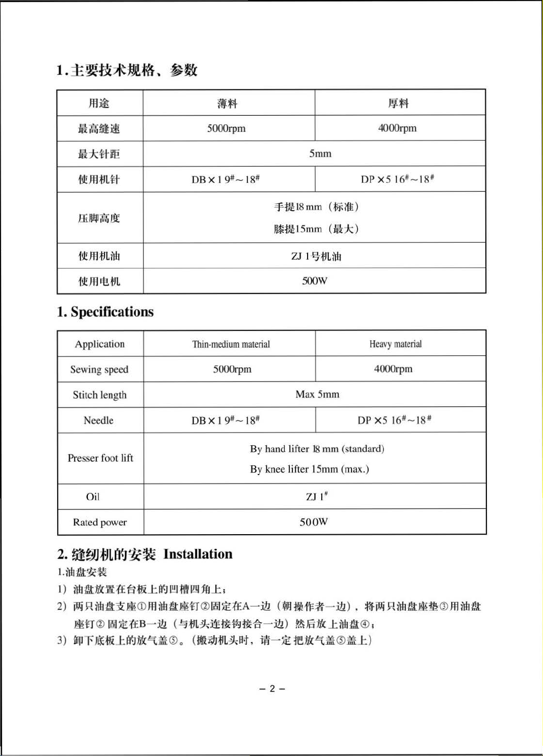
1. Specifications
Application
Sewing speed
length
Stitch
Needle DB X 1
5000rpm
DB X 1
Thin-medium
9#-18#
5000rpm
9#-18#
material
Smm
~tlt18mm
111tm:
15mm (-Ji);:)
z1
Ma
1
·
~-
m
500W
x5mm
(~(ft)
nn
4000rpm
DP
X5
H
eavy
4000rpm
DPX5
16#-18#
material
16#-18#
Pr
esser foot lift
Oil
Rated power
2.
~~Jmt¥J~~
Litl:l./lt~~
1 )
ntre.t
:It<
ft
1£
a
2)~R~~~~~Jtl~~~fl®~~~A-~(~~~~-~
~n®~~~B
3)
•~••J:~:It<
Installation
:t&
J:
atH!!l
.fltm
1ft
J: ,
- ~<~•~~~~~~
~~®o (m~m~H,a-~re:Jt<~m®~J:)
By hand lifter
By knee lifter 15mm (max.)
- ~)~Fo:tt<J:~a
- 2 -
18
ZJ IH
so
ow
mm
(standard)
),
~~R~~~~®m~~
®
,
Page 6
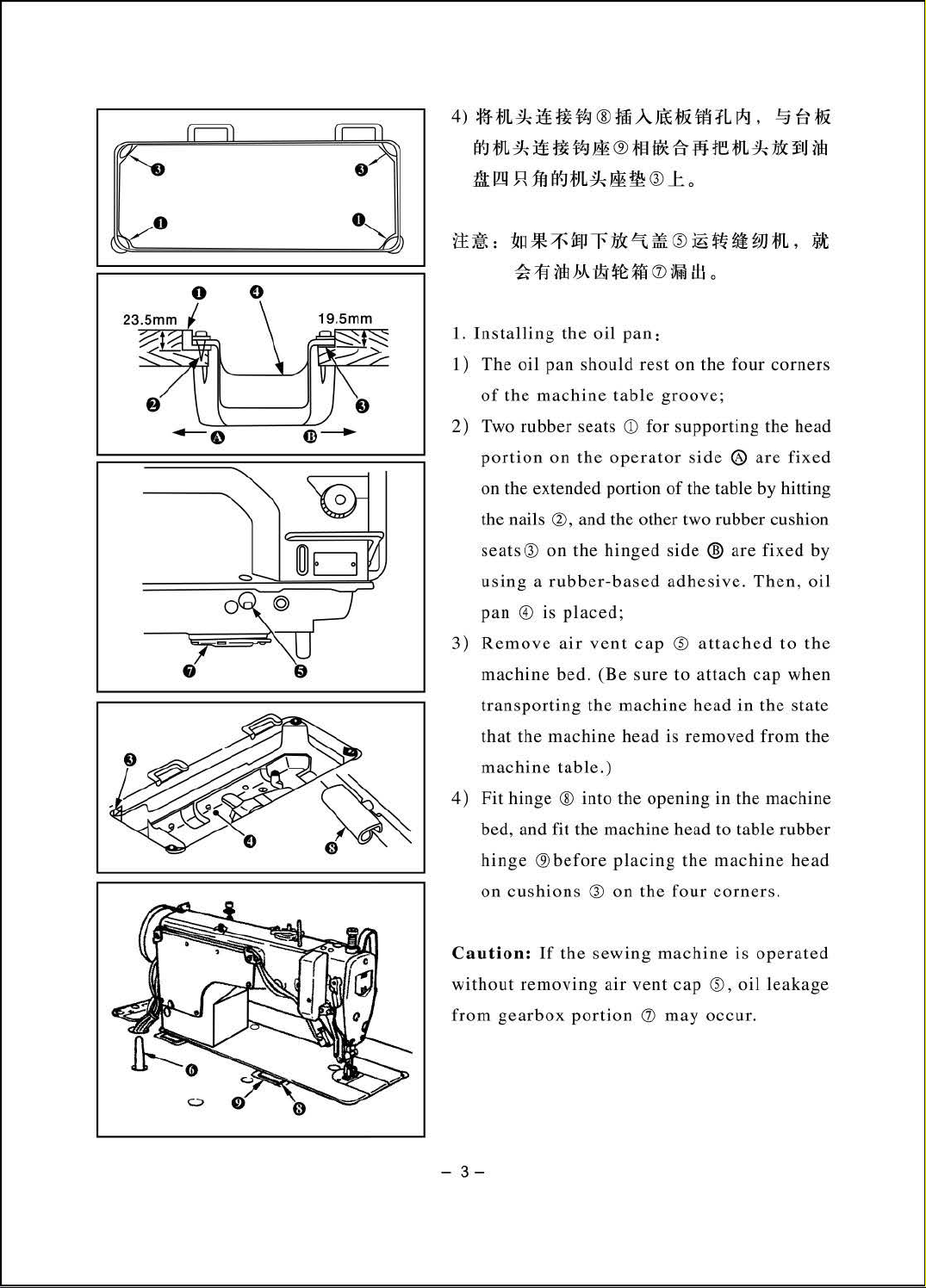
4)
:I~HJL
~
:itf
f&
fZ.J
®
:Jili
A
m;
tlHili
:fL
P-1
,
.!:§
€?
~
0
~m~:itf-~
till9
.R]M
~•:~-~~~-~-
~~~M itH
1. I
nstalling
1)
The oil pan s
of
the
mac
2)
Two rubber s
portion
extended portion
on the
the nails
seats
Q)
sing a rubber-based adhesive. Then,
u
pan
@)
3) Remove
&®a&
~tJL~&m
~~<D~tf.lo
the
oil
hould rest on the
hine table
eat
s
on
the
operator
Q), and the other two rubber cushion
on
the
hinged
is
placed;
air
vent
~wrem~•~~
Q)J:o
~~
ft•wm.a
pan:
groove;
CD
for
support
si
de ® are
of
the table by hitting
side ®
cap ~ attached to
four
corners
ing the head
fixe
are
fixed by
oil
the
d
mach
ine
bed. (
Be sure
transporting the
that
the
machine head is removed from the
machine
4)
Fit
bed, and fit the machine head to table rubber
hin
on
Cau
tion:
without
from
gearbox
-
3-
table.)
hinge ® into the openi ng in the machine
ge
®bef
cushion
If
the
removing air
machine head
ore
placing
s
Q)
on
sewing
port
ion
the
machine
vent
d)
to
attach
the
machine head
four
corners.
cap
~
may
occur.
in
is
.
oil
cap
when
the
state
operated
leaka
ge
Page 7
3.
JWi;JJi~Jl::ff-jl'~Ji:(J'1iJ.';J~
Adjusting the height
.&.
f£:lJ.
,
1>HJill:iJ!!
~
Warning:
~
4.
~?>f!IY-J"tif11&
Thrn
of
the knee lifter
J
JIJL(l'.J
:ll:~
r<i:
iii
OFF
the
power
abrupt
start
before
thread
caused
by
Installing the
J.
il11d>:iot!
ii!/.Z.JiiJ!iili'I
H\lfF.
starting
the
work
so as
to
of
the sewing machine.
I.
2.
lt.fr.,
ill'l;'l'iit~iJ!!JJ~
'lffi~
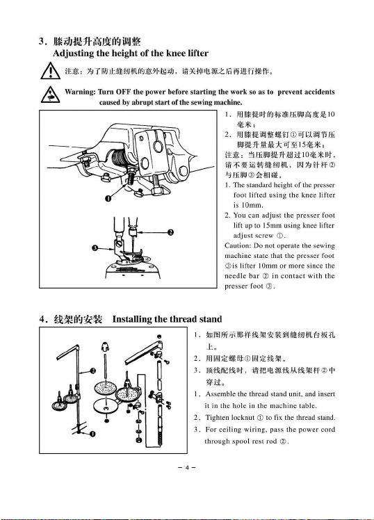
1. The standard height of the presser
foot
is IOmm.
2.
You can
lift
adjust screw
Caution: Do not opera te the sew ing
ma
chine s
@is
needle b
pr
esser
prevent
!I!I!H.lnt(l'.Jlii~
~*'
!I!I!Utii!J
l\'ll!!!trCD
~t:Hrliliil-*"'"'
~lli~!IHhllltll
())
~lillil!.
lift
ed usin
g the knee
adju
st th e presser foot
up
to 15mm usi ng knee lifter
CD.
tate
that
lifter
the
IOmrn or more si nce th e
ar
(1)
in
con
foot Q).
stand
I.
•oo•~·lf··~··iJ!!JJIJL8.R
J:
.
2.
!llllii1EI:!!JltCDiiii1EB!.I\!.
3.
••~•M.
~u.
I.
Assembl e the thread sta
it in
2.
Tighten locknut
3 .
For
throug h s
mre•••Ma•w
the hole in the mac
CD
ling
wiring,
pool rest rod
to fix the thread stand.
cei
nd
hine
pass the p
Q).
accidents
t
lli~i\l;IJ
U€
10
llJI;.(
ii!Ji'illi
1s**,
D/Glltllt
L.
IN1J\tlf0
lift
er
pre
sser
foot
tact
with
the
(l)
•
unit, and insert
tab
le.
ower cord
,
-4-
Page 8
5.
:bnifll
Lubrication
&
t:t:
~
:
t:J
T
l!lLtl:
Warning: Turn
caused
~~]mat~
OFF
by
~)'~t9
the power before starting the wo rk
abrupt
~),
start
of
the sewing machine.
TR :¥dlji
It!
i1Jj{
zm
~~~~JH
nil
m
1.
2 .
3 .
4.
¥£~:
1 .
¥I*
rr
11
~
0
so
as to prevent
JLZ.M,
9='
1Ju
nil
t~J.iH3HJL1Vti~,
:};ff
J:
0
ffll
r
1Jn
nil
o
at~
f81Ju
nil
{i£
1Ju
A
i~He
nil1Jn m ¥lh1t
it
0
TR
11
!.lf.
1Ju
M~.JAilBM~-9.1L~
~
1st
~
~
1m
IE
~m~~JHJLar,
®
m¥1JM:IH~7Fm
ff
~l
LV-
r ,
iW
:tlHr
-tt
.m
Wr
~~31m
~m
a~~~JJ;j:JLBf,
-
3soo~t7titP
m¥I1~.m
0
accidents
ti\f-~tttifE~
#st¥IHJL*x
~
<D
,
1~
.m
llfHW
ZJ
1 -5
;j:JL
nil
o
:m
®
at~
~IJ
~
111:
nilli
~
at~
-m
,
:YL
lli*,
'ffi'
1JU
ilB
at~~~
:!ln.*M
®
nn
M 0
Wt~ -~at
-I1L
o
:!if~iF
at~r~u
1iiJ
¥5t
;;g
TR9CJH:rr3ooo
f8ll-€1
~~z.
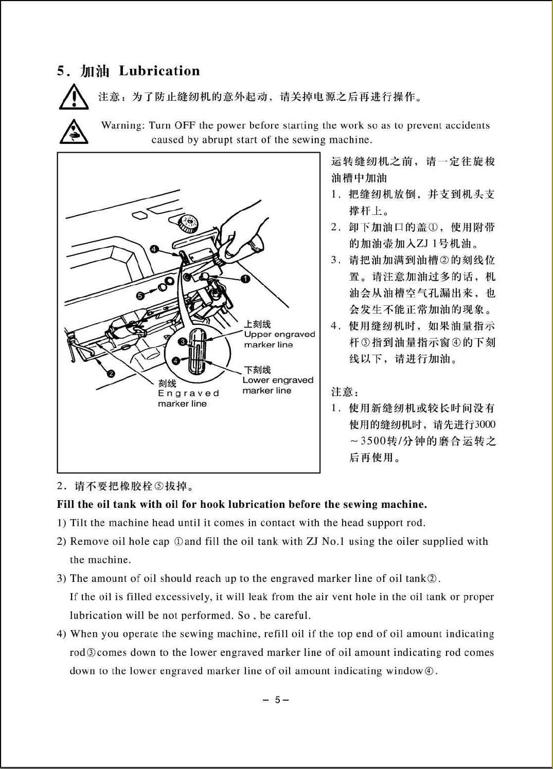
Fill
the
oil
tank
with
oil
for
hook
lubric
ation
1)
Tilt the
2)
Remove
the
3)
The
If
lubrication will
4)
When
rod® comes down
down to the
machine bead until
oil hole
machin
amount
the
e.
oil
is filled excessively,
you
operate
cap <Dand
of
oil should
be
lower
it
com
es
in
contact
fill
the
oil
tank
reach up
not
performed. So
the
sewin
g machine, refill
to
the lower engraved marker
engraved
marker
it
to
the engraved
will
leak from
, be carefu l.
line of
-
before
with
oil
oil amount
5-
the
sewing
with
the
head
support
ZJ No.1 using the
marker
the
air
if
th e top end
line
line
vent
hole
of
oil amount
indicating
machine.
rod.
oiler supplied
of
oil
tank
in
the
oil
of
oil
amount
indicating
window®.
®.
tank
or
ind
rod
with
prop
er
icating
comes
Page 9
(Caution) J.when )tOu use a
new
sewing machine or a sewing machine
after
an extended
period
b
2. Do not remove rut>bcr plng(i)
6.
••Mhl~~•c•m~~~m
reak-in
uf
disuse . run
your
Adjustin g the amount
&
~
t±:Gl:,
hniJi.ll~H1J=l1
A Warning: Turn OFF t
caus
ed
by
l
t'tJ:Q:~
he
power
abrupt start
machine
of
oil in
I
·~
·~I.
before star
uf
at
J,OOO
M
~M~)
the
hook
iti*W
the
r
!J.~l
~Jti
ting
the work
sewi
ng mach
~
#Hhi,l/11
I .
~I
]
\'i
ti·~
uma.
l;IJ)
~~hh.r.tW1>.
to
3.5
00rp
rn
for tltc
t
t}:liH
:i
l
~ft
.
•o
as to
pr
evcn)
ine
.
&i!l'l1
;\It
ilk
i.I~-W!ll!{
fit}
;:
( '"'
:t
H~iJI)
•~•aw•.w•
h!E./11
purp<>Se
accidents
'H <D:il~il',J
iilt
Ji'(
of
•,•;.
ulfri~
<~
~•
(iU!)
2. 1
SCI'C
I . Adjusunenl
in the hook ,
(C
J.
~l;!iJ~
m.
\Cm
RP
I;dl1 ( T-1-:l
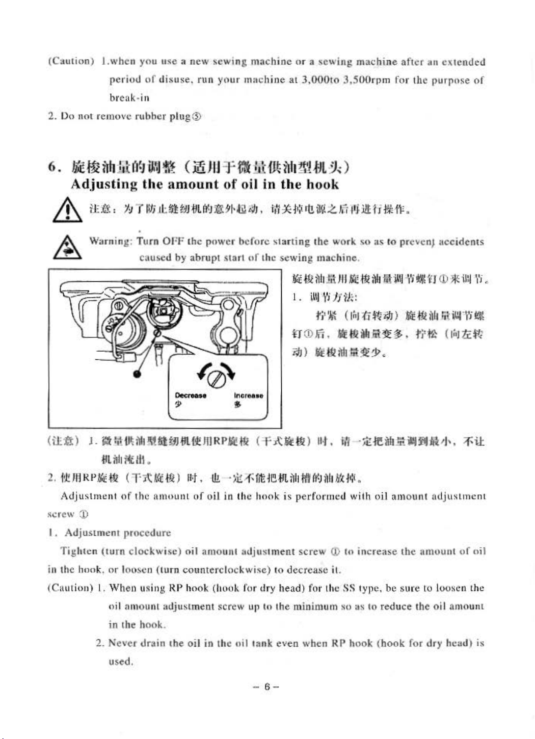
Adjustment
\\.' :I)
Tigh1cn (I
nulion)
I.
2.
ilh,.H
iHJJllla! lll
ilh
i't
Ill.
r.i
~)
of
the nmu
procedure
urn
cloc
or loo•c
When usi ng
Hi I am ount adjustment screw
in the hook.
Never
us
drain
ed.
kwise
n (
turn
unL
) o
counterc lockwis
RP
1he oil
RP
II!#I
111'. ·
l!!.
·
>k.-f;
of
oil
in the h
il
amo
unl
ho
ok
(hook fur dry head)
in
the oil
(
-f
A':JE
Ill
f,t
JB:flt
~lrh'Ht~
onk
is perf'ol'mc.d with
adjus
1ment sc•·ew (I) to i
e)
10
decrease il
up
to the minimum
lank
even when
-
6-
)
fo•·
ll·
t.
l1h
t
he
RP
lt1
·
It
IJH:i.
ncrease
.
SS
1ype, be sure to loo
so
as
to
hook (
fl!M~illfUi~'''.
oiJ
amount
the
reduce the oi l
hook
ncljusLmc.
amou
for dry hcad)
;r-iJ:
nl
uf
sen
the
amounL
nL
oil
is
Page 10
7.
Mf~t.iHrb
-§i ( ftb~)
Adjusting the amount
IY-Jim1~1Jl!
of
oil
(oil splashes) in the hook
Warning:
<D
Amount
<D
of
i!IIA(iflli1t)~i-A1t.lfl~lt
E
E
U[
l I
11...-
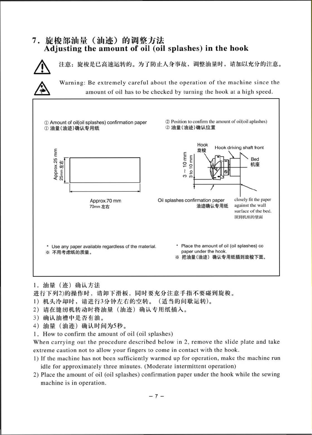
• Use any paper available regardless
*
;r-m~.tt~tt-.Jm•
Be
extremely
am
ount
of
oil( oil splashes) confirmation paper
-------!
Approx. 70
70mmliti
.
careful about
oil has
mm
of
the material.
to
be
1
checked
Oil splashes confirmation paper cl
the
operation
by
turning
Q) Position to confirm
Q>
ilb:ll
Ulbi2E>
~i-Aitl
~:k
~!
1 2 ,
(')
(')
;drit!.i.A:1Hfl~
• Place the amount
paper under the hook.
* teidlil
U!Bil!l
of
the
th
.
I
the
machine
hook
at
e amount
J;
cr
.i.A.'lt
of
H
ook
driving shaft front
h~~
~
-
'---
against
surface of
TJiJIJM(J()!lliJii
of
oil (oil splashes)
Jll~fifiitJMEUll'im.
since
a hi
gh
oil( oil aplashes)
the
speed.
~e~
ose
ly
lit
the
paper
the
waU
the
bed.
co
1.
~
li1
( ~ )
Tiff
J
iA
15
'lt
:itHi
r
~r
j
2)
~1'-J
~~It-
t
,
iff
fiji
r
i1f
:f1i
,
1m
at~
1f.
?t
11:
~=f.
j~
=l~ * ~~
I )
;tiL~
It
~
I
P·
l',
~:itt
fj
3
?t
itjl
1C
;{J
tf.J
~
~
o (
~
~
tf.J
1
~11
ijX
:i6
~)
o
2)
~a~wm~~at•~•(M~)•~~m•MA
3 )
r~ffri-A
iw
f\'~
r
t•
:f€
~ ~ M o
4)
nil
iil
1. How
Wh
en
carry
extreme
1) If t
he
idle
2) Pl
ace
machine
U\:1! ~ )
to
caution
machine
for
approximate
the
Tdfri-A
confirm
ing
out
not
has
amo
unt
is in op
at
fij]
T:J
the
amount
the
procedure
to allow
not
been sufficiently
ly
three
of
oil (oil
erat
ion.
5 fy o
of
oil (oil splashe
described
your
fingers
minutes. (Mode
splashes)
confirmation
to
warmed
-7-
below
come
rate intermittent
s)
in 2, rem
in
contact
up
paper
o
ove
with
for
operation, make
operation)
under
the hook while
!l
j
ME~
the slid
the
hook.
o
e pl
the
ate
and
machine
the
sewing
take
run
Page 11
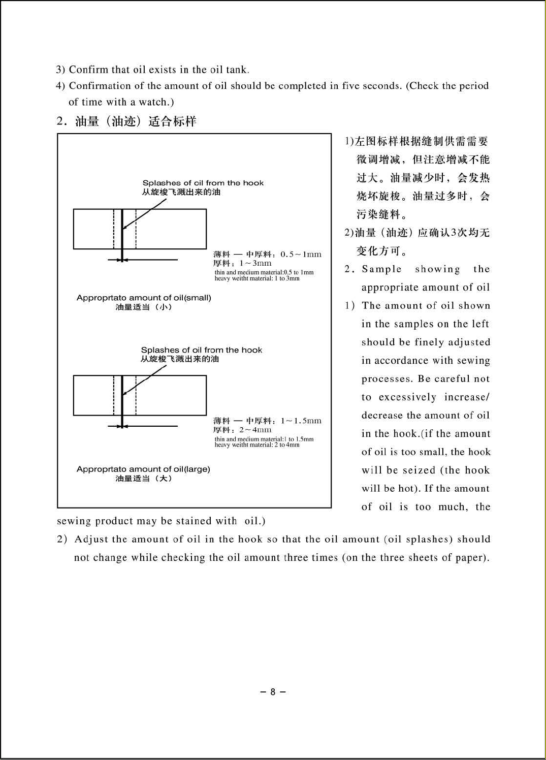
3) Confirm
that
4) Confirmation
of
time
with a
oil
exists in
of
the amount
watch.)
the
oil tank.
of
oil should be completed in five seconds. (Check the period
1
)tc
oo
t;-r-~m
:~m~
ifjfJ
-t~~
~ ~
!W
' '
: :
' '
' '
Approprtato
Approprtato
Splashes
J..A.:tE~~~tfj
of
/
)Jb
fi'i
amount
of
~~
Splashes
JAME~~~Iil
oil(small)
(Jj\)
of
/
~
:
'
'
amount
)Jbi!;~~
of
(;k)
oil(large)
oil
from
*Wlidl
oil
*Wlidl
the
~*il-
J!1*il-: 1 -
thin and
heavy weilht material: I
from
the
alf;t-•t•J!l!:f;t,
J~*il-:
thin and
heavy weit
hook
-
<j:o}!j(:jsj.
3mm
medium
hook
2-
4mrn
medium mat
htma
,
0.5
mat
erial:0.5 to I mm
to
1-
eria
l: I 10 I.Smm
terial:
2to
- l
3mm
l.Smm
4nun
mm
-VIt~~~'
U:koni:J
~
ff-
WE
fj
~~.Mo
2)
ilb
it
~1-t:IJRJ
2.
Sample
appropriate
1) The
in
the
s
hould
in
accor
proc
to
excessively
decrea
in
the
of
oil is too small, the hook
will
will
f
fl.tt~
.fl
~d>IJrt,~lt~
ttL
im
it
(
ilB ~ )
0
Ell
s
howing
amount
amount
samples
be
finely
dance
esses.
be
be hot).
Be
se the
hook.
amount
(if
seized (the
If
it~:::f'ffg
:i:t
~
1Ft
, ~
1iffriA
3
(X~
7C
the
of
oil
of
oil
shown
on
the
left
adjusted
with
sewing
careful
not
increase/
of
oil
the
amount
hook
the
amount
of
sewing
2)
Adju
not
product
st
the
change
may
amount
while
be
sta
ined
of
oil
checking
in
the
with
the
oil
oil.)
hook
amount
so
that the
three
oil
times
amount
(on
the
-8-
oil
is
too
(oil splashes
three sheets
much,
) s
hould
of
paper
the
).
Page 12
8.
lJL
*tf.J
~~Jj
r!
Attaching the needle
Warnin
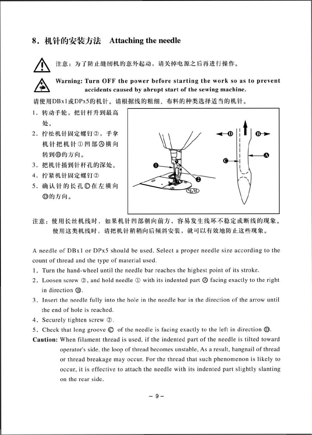
i~i!l!JffDBx
1.
~i;JJ=f~, tEHff7!-~
2 .
:JY
t~
-tJL
tJL H tE
!ffl
flj
®
3.
retJLtf
·
4.
:fi'
~
fJL ~ lili
s .
rdfJ
iA
~
1·
@1¥]
:11
it~:
~
ffl
g:
Turn
acc
idents
I
!!X:DPxSJ'f.JtJUt
~t
IE
:iE
u~
n
<6J
tJ
L
~
I·
<D
1!!1
t5
B ®
I¥J
15
,.,
J 0
M~J~t·tr:fL(J'g1~~
l
:;E
Ul
t
.r
a:>
((~
*:
:fL
©
:££
lnJ
0
*:
i~
tJL~B·t,
Rm~•m~~.
OFF the
o
IJ:lti
•
=v-
*
~
rl:iJ
-
.li:
~
!RJ
"!ell
*t1LH
mremHMm!RJ~~~~•.
power
caused
i#;fllm~a~*JHHI,
r~
1!!1
before starting the
by
abrupt start
;{Jlfi.fl~~~~~ft~
$.f}I
!RJ
flu
15,
of the sewing mac
~ ~ ~ ~ ~~7f'fj~
-~~
work
«-
so as
hin
~
a'~tJLH
~M~~®••
to
prevent
e.
o
Wtlfi~
~m!~
·
o
A
needle of
count
of thread and the type
I . Turn
2.
Loosen screw (6), and hold needle Q) with its indented
in dir
3 . Inse rt the needle fully into
the end
Securely tighten screw
4 .
5. Check
C
aution:
DBxl
or 0Px5
the hand-whee
ect
ion
@.
of
hole is reached.
that
long gr
When filament
operator's side, the loop
or
thread
occur,
on the re
oove © of
breakage
it is
effective
ar
side.
sho
of
l until the n
(6)
.
thread
uld
be used.
material used.
eed
le
the
hole
in
the
needle
is used,
of
thread becomes unstable, As a result, hangnail
may
occur. For
to
attach
the needle with its
Sel
ect a proper
bar reaches
the
needle
is facing
if
the
ind
the thread
-9-
nee
dle
the highest point
part
® facing
bar
in the direction
exact
ly to the l
ented
part
of
th e needl e is tilted towa
that such phenomenon is
indented
size a
of
exact
eft
in
part
cco
rding
its stroke.
ly to the rig ht
of
the
arrow until
direction
slig
htl
y s
to
@.
of
thread
likely
lanting
the
rd
to
Page 13
9.
~JL'ff.J:t(~JJ¥*
Setting
the
bobbin
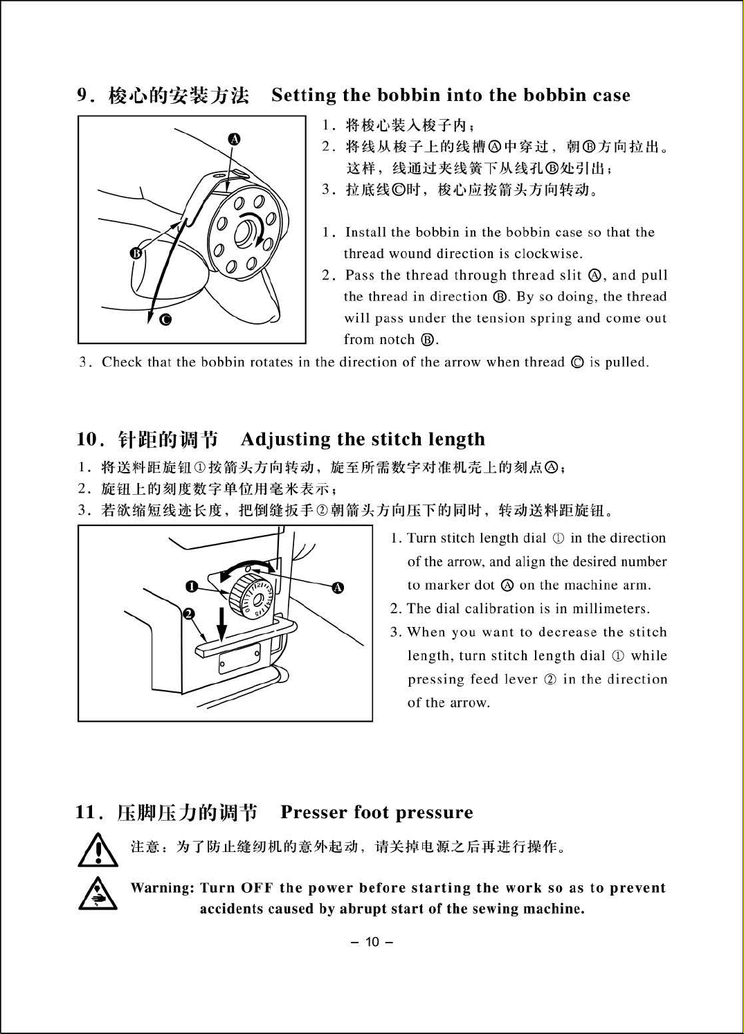
1.
¥-t~·C.\~A.~JFF-1*1;
2.~~M~~~~~~®~~li.
:i!t-f,
3.m•~©"·•~m••~n~ft~o
~:ilii:i:1*~•-rM~1L®~sllli;
into
the
bobbin
~®n~~lli
case
o
3.
Check
10.
1.
•mMm•m
2.
•m~~~~•*•~m~*~~~
3.
~---~~*~·
that
the
bobbin rotates in the
li-~eEI9iPfP
ro
Adjusting
•n~n~ft~.•¥~••*~•m~~~~A®;
re••••®~•~n~ffir~~"·
1 . Insta
2. Pass
ll
thread wound
the thread in
will pass
from notch
direction
the
stitch
the
bobbin in the
direction
the
thread
under
of
through
direction
the
@.
the arrow when thread © is
bobbin
is
clockwise.
thread slit
®.
By
tension
length
ft~mMm•mo
1. Turn stitch length dial
of
the arrow, and align the desired number
to
2.
3.
marker
The
When
dial
calibration
you
dot
® on the
want
case
so
®,
so
doing
, the thread
spring
to
and
00
in the direction
machine
is in millimeters .
decrea
se
that the
and
pull
come
pulled.
arm.
the
stitch
out
l
ength, turn stitch length dial
11.
&
A
ffi
JJ!P
ffi.1J
1±
~ : ~ 7 ~
Warning: Turn
tl9ili'3il
J.l:.
;.]]
OFF
acciden
ts
Presser
fJL
~
~
the
power before starting
caused
foot
:9Ht~
i;IJ
,
by
abrupt
-
10-
pressing
of
pressure
ilt
*Wit
start
the
of
tuit
the
feed lever
arrow.
z m
~:itt
the
sew
ing
fJ
~
1'F
work
machine.
® in
o
so
the
as
ro
direction
to
prevent
while
Page 14
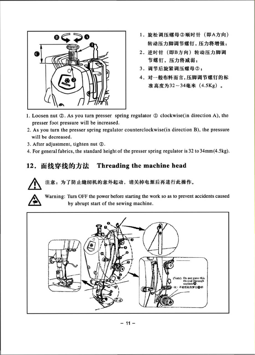
1.
ME
t'k~
.ffi
•
-at
® .lllflt
tt
(
ep
A:n
riiJ
>
$t~.ffijJ
2.~1flttt
"'WtJltJ
3.
W"'W
4.
~-tim*4ifii
$11Jlt~32-34•*
1.
Loosen
presser foot pressure will be increased.
2. As you turn the presser spring regulator counterclockwise(in direction B), the pressure
will be decreased.
3. After adjustment, tighten
4. For general fabrics, the standard height
12.
nut
a>.
As
you
turn
presser
nut~.
ifiitl~tl~:1i~
Threading
spring regulator
<D
of
the presser spring regulator is 32 to 34mm( 4.5kg).
the
machine
-~"'WtJltJ
(~B~riiJ)
t
.ffijJ~Jljj
.1511E~i"f.ffiMtHi
"B". HiWiii"'Wt~tr~~
clockwise( in direction A),
t
.ffi1J~jft~
$t~ffi1JW.
I
®
I
(4.5Kg)
I
o
the
head
Warning:
Thm
OFF the power before starting the work so as to prevent accidents caused
by abrupt start
of
the sewing machine.
-
11
-
Page 15
:n~,
A
~
:
)~S-----...-~~~
>
••~~~~*~•~~••-w"~fi•tt•;
~
t
~~
~
777777777?dtlr''77777"
B
W
~Y.
6.
~-~~••••~M.
®.~
Q)~·ll
r&JE.flJ~M~l;n®.
®~~~~
~·~*~~.
:
.
~·~*~·
®:ntn:~
•w~••
>~···~"·
8~~ij*~ft<V
••~-~~&•m.m~~•n®~•
7.
~·~~~~*~"·~~~~*~·~®*fi~··
11~
:
1.
•••~"·•a•~~~*~acvzoo~~~~~*~•~.
2.
~ana~"~-~~~~"'
~~*mf!J:il!:rr.
~~00®~~-~~*~-~tt•
~~ttll.
;
Mffl~~MM·ff~~R~~W*,
-
12-
.
~-··~~.
~~00®~~
re•~M··~
Page 16
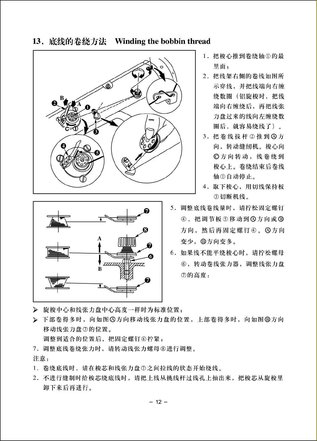
1)
Insert
the
bobbin
deep
into
the
bobbin
winder
spindle
CD
until
it
will
go
no further.
2) Pass the
stand
following
end
of
the
after
winding
coming
3)
Pre
ss
the
The
bobb
win
der
4)
Rem
ove
5)
To
adjust
th e
bobbi
setsc
rew ®.To
6)
In
case
turn
the
);>
It
is
the standard
tension
);>
M
ove
the
bobbin
from the bobbin thread tension several times to wind
bobbin
in r
sp indl e
the
the
n win
that
bobbin
disk.
thread
the
order as
bobbin
posi ti
thread
clockwise
winde
otates
bobb
the
in
the
CD
au
tomatically
in
and
winding amount
der
adjusti
the
direc
bobbin
thr
ead
that
on
of
pulled
r trip
thread
tension
the
the
out
shown
on
the
the
end
latch
direction
cut
the
ng plate ~ to
tion
of®: Decre
is
to adj u
center of
thread
from
in
the
bobbin
of
as
bobbin thr
of
not
several
the
bobbin
Q)
in
the
of C and
soon
the
bobbin
wound
st
the
the
tension disk
the
spool
figure
dire
the
as
the
ead
th e
ase;
eve
height
bobbin
rested
on
the
left. Then,
times.
thread
ction
winding
with
thr
direction
to
nly
([)
(In
, wind
of@
bobbin
ead, loosen the
the
is
thread
is finis hed.
the
thread
of®
direction of@ : In c r
on
the
of
the thr
as hi
gh
to
the
direction
on
the
right side
wind
case
of
the
aluminum
counterclockwise
the
bobbin thread with
and s
tart
the
is
wound
cut
reta
iner
setscrew ® and
or
@. Then,
bobbin
ead
as
, l
oosen
tension
the
center
of®
of
the
clockwise
the
sewing
up.
The
Q)
.
tighten
ease.
the
nut® and
disk
([)
of
the
as shown
thread
the
bobbin,
thre
ad
ease.)
machine.
bobbin
move
th e
.
thread
in the
figure
bobbin
the
winding
After
7)
To
adjust
Caution:
1.
when
the
bobbin
2.
Wh
en
needle thr
hook.
on
the left
is
excessive
the
adjustment,
the
winding
and
winding
ead
when
amount
tension
the
bobbin threa
thread
the
from
the
windi
and
to
of
the bobbin thr
tighten
of
the
tension disk
bobbin
the
thr
thread
ead
the
direction
the
bobb
d,
path
ng
nut
in
start
([)
in
amou
nt of
ead
®.
winder,
the
is
tense.
th e
state
of
thread
-
the
of®
on
the
turn
winding
take-up
13-
as
upper
the
that
bobbin
shown
part
thread
in
the
wing
and
thread
in
the
of
tension
sta
te
is
not per
remove
on
figure
the
that
the lower
on
bobbin
nut
®.
the
thread
formed,
the
bobbin
part
the left
is
excess
between
remove
from
of t
he
when
ive.
the
the
Page 17
14.
~tt~*il
f.riPd
~
Thread tension
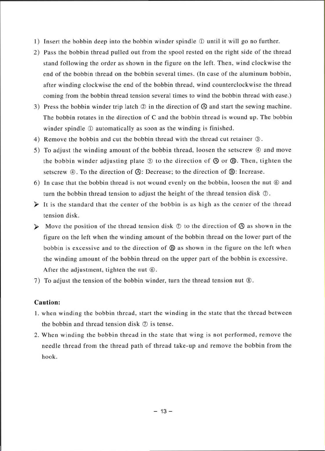
1.
ffii~5~1J
1)
fB!ii~*jJ~~HJ:CDJIID'i"#~~
frtl~~
2.
Ji\H.H~
l)ffl~*:1J~U®~~®~~~ft-.
2)
1.
Adjusting
1) As you turn
the
2) As you turn
3) As you turn thread
will be increased.
4)
As you turn
decreased
2.
Adjusting
1) AS
2)
:1J
U9
iJijJ
~
rf'iJ
tc ®
f8
:17
rf'iJ
R ~
9!IJ
~
mi
the
needle
thread
needle
tension will be increased.
As
you
will be decreased.
you
after
nut
nut
.
the
bobbin
turn
tension
turn
screw ® counterclockwise
thread
tension
thread
CD
Q)
trimming
counterclockwise
tension
counterclockwise
thread
adjust
-~*:1J~-;
o
tension
nut
CD
clockwise
will
be
shorter.
(in
direction
nut
Q)
clockwise
(in
direction
tension
screw ® clockwise
(in
(in
(in
direction
direction
<®:1JM)~i;JJ,
2)
fBffii~5~1J~~HJ:CD~at~i
(®nrRJ)
~j};
3)
fB~*JJ!t~HJ:<bl~~©~~ft
• '
4)
fB~*JJ!t~HJ:<bl~ti:©~~~
'i;IJ,
direction
@
),
the thread
@)
,
the
(in
direction@),
®).
ffii~fi9*1J~
-
~M
!ffl•.
ffii~5*1J~~!il;
ffii~S~1J~jjo
@),
the
thread
length
©),
the
needle
need
le thread
the
bobbin
oo~~*JJ
remaining
will be longer.
thread
tension
the
bobbin
thread
on
tension
will be
thread
tension
15.
~~
ttit
f.riPd
il
Thread take-up s
1.
~E~
..
fl!~ilfrtliJJil:
1 )
hiE
f'~
~
1fr
~ u
Q)
;
2)W~~~u®amM~:n~
(~®:n~)R•"·
-14-
pring
•~•frtl•~:~t•~*'
Page 18
(f!ll®!JriiJ)
4)
t~
~ ~
ij{
n
~~JA
·t,
<»
!:vJ
~
1!l~~
.
H~a~*:h~:ll:-.k
1t-t
H
11
lllJ
(
f!P
®
11
lllJ
;
)
~
J9
Jif1
3)
2.
I )
2)
3 )
,
1!l~
~ ~
re~~.u~-:n<»~~lf1#1511lJ
(
E!IJ
@
1J
[Rl
)
~
i;IJ
lf1
,
1!}~
~
Wfl'ttl~~ftthttps://manualmachine.com/j\0
1!J~~~~Il:1J
MEt~
1E
~
~
mt
.r~
~ m
~U
l!~j
t~ ~ ~JH~aT
(t1
ryll:
:1J
~~i'i:
1ft
tm
!fl
(ID
ftf:
) 1
~
n ® •
Q)
I
:m
-
~!X
<»
/J, o
a>
~
,
~
ti:PJ~
1=t
~
!®i
1t1
ft
7;tJ
11
~
~
lllJ
~~.m•~wrm.m~m~
71
'
IT:i
~
m
¥r
:ilHr
iflll
~
o
X
•
~~~I¥Ji71l::t.Ju~m,
i;IJ1'J:~tfl~M
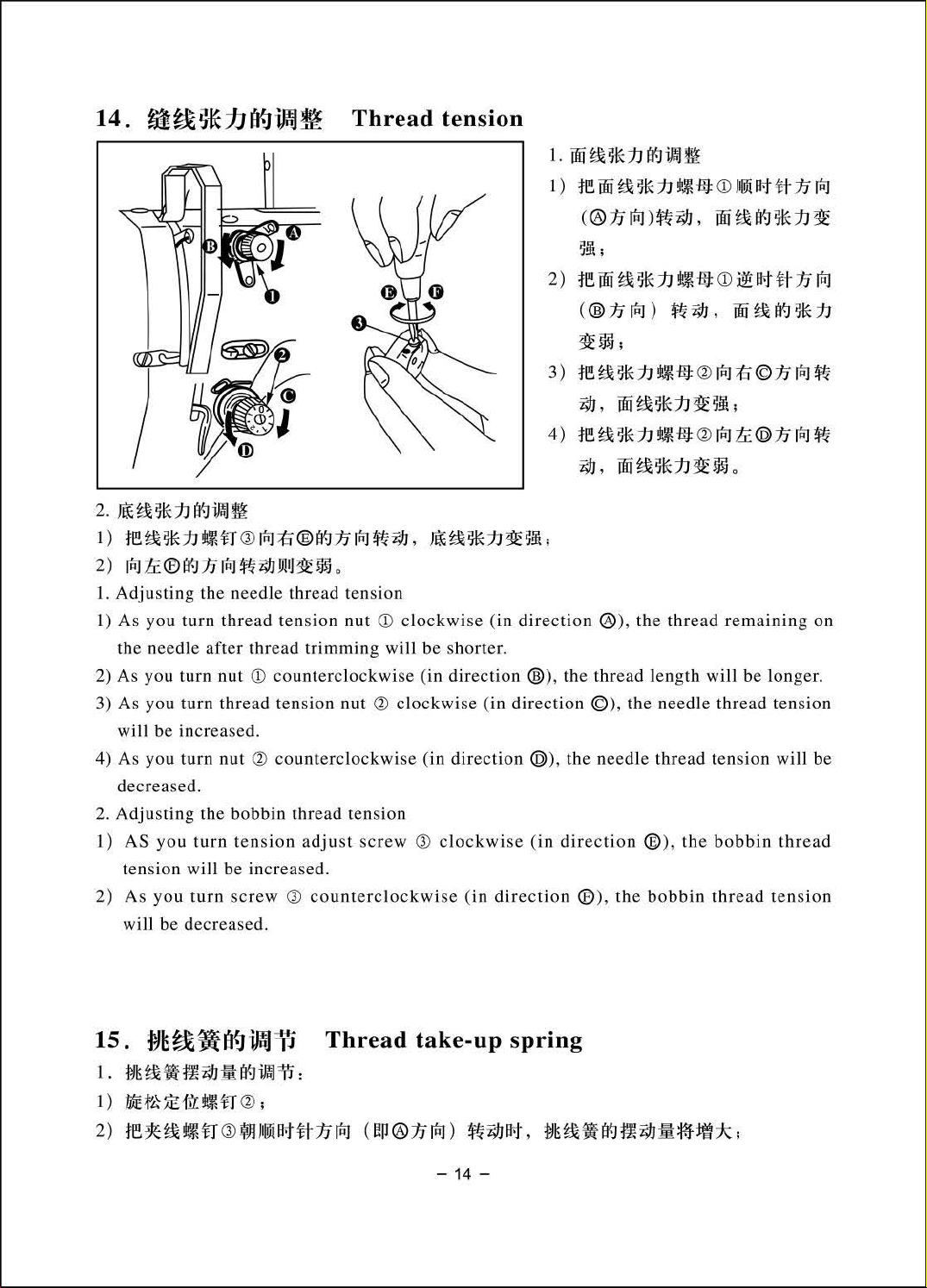
• When the
midway, thread
tens
ion
of
thre
the
•~•i1oi~~~~~~11~:•~•~•~&1J~•Mm.
•~•s~•~a~m•~nm~®~••~i;IJ.••~•~•~ffi1J
1.
Changing
1)
Loosen setscrew
2)
As
you
spring will
3)
As you turn tension post
2.
Changing
1) L
oosen setscr
2) Loosen setscrew
3)
As
you
turn
the
turn
the s
ten
be
pressure
ew
ten
troke
a>
sion po
increased.
a>,
@)
sion post
r.JT~
8 titmlli*
ad
take-up
is
fed
thread
.
.
of
st
of
and
take-up spr
thread
Q)
Q)
counterclockwise(in direction @
thread
remove
Q)
s
w•~•o
out
spring
from
moves
8
ing
take-up
clockwise(in
take-up spring
thread
clockwise(in
R~a~~*•~aMdMa~a~~t.t.
up
to
since
the
is
high
.
spring
direction @),t
<D
tension
direction@), the
~
.
•
1!J~~
m-
• The
thread
works
he stroke
),
the stroke will
pressur
0
}[i;I
J1t=f!J/&.f§
take-up
up
to
the
mw~~®n~~w
of
e will
last
o
the
spring
.
thread
be
decreased.]
be
increased.
take
.
~
-up
-
15-
Page 19
4)
As
you
turn
ten s
ion
post
decreased.
ually, upon
Us
only
while
jud
s n
ot
ge
works
thread in
In
add
work
To
pring
s
needle
performed. When it do es not
spring.
doe
the
sew special
the work
up to
ition,
of
the
the
direction
the
properly.
machine
material
the thread
la st
stroke
For
Q)
counterclockwise(in
coming
thread, it
before
of
work
of
the
general fabrics
take
-up
needle
@after
up
to the
the
thread
out, all
need
spring,
the
the take-up spri
to
be
adju sted
confirm
thread
last,
is
pressure
decrease
take-up
, a
stroke
pull
of
spring
dir
ection @),
aga
whether or
ed
out
the
thread take-
the press ure
is
excess
of
10
to
the
pressure
ng ha s be
in.
from ® when
13
en
adjusted
not the thread
up spring
of
the thread
ively small,
mm is
proper
pu ll
the
will
take
ing
has
take
.
well
been
spri
be
,
-up
out
-up
ng
16.
~~tt~fj;J~
&
tt~
A Warning: Turn
. accidents ca used by abrupt
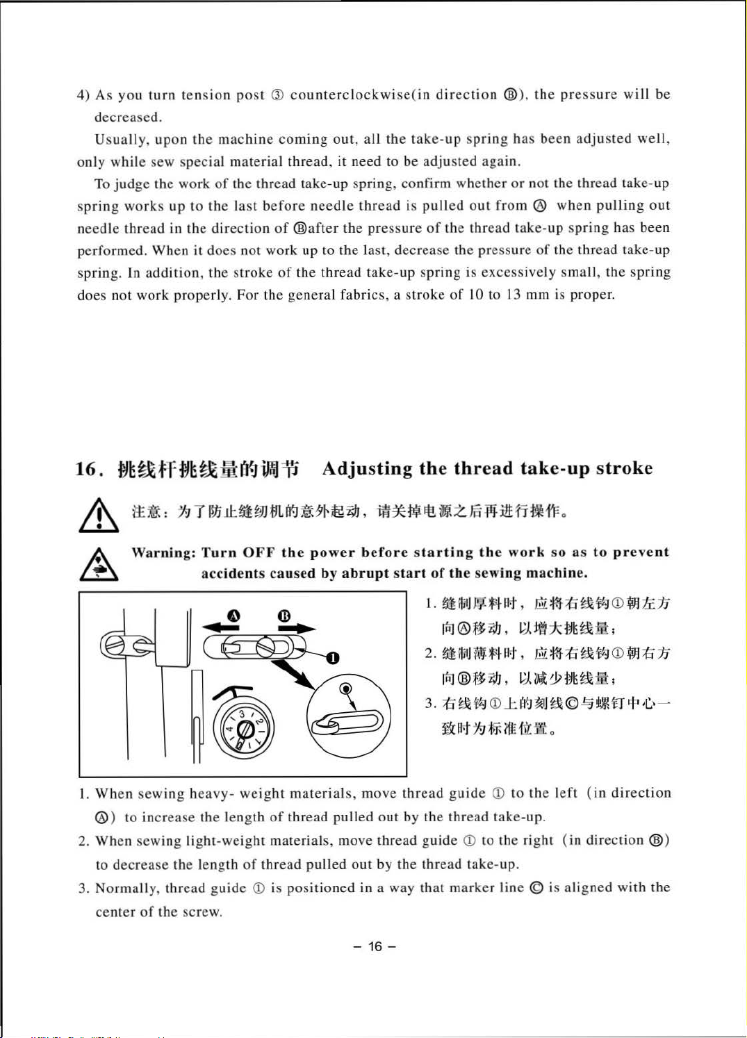
1. Wh
en sewing heavy-weig
@ ) to in
2.
When
to decrease
crease
sew ing light-we
tt:tl
:
19
Tltli
the
the length
a91JJil
Adjusting
.tUi;>JJ11Ut'~~;r~~f9J,
OFF
the
power
ht
materials, move
length
ight
of
thread
of
thread
materials,
pulled
pulled
move
the thread take-up stroke
m'*W~
befor
sta
out
thread
out
by
li:Z.m¥ll!tfi.f'F.
e s
tartin
rt
of
1.
2.
3. ;(:j
thread
by the thread take- up.
guide
the
thread
g the
the sewing machine.
~
111tJ
rRJ
®~f9J' L;l.it77c~~~fh
~
ffli
[l:ij
@*:t
~1#:1
~
IJ.t
guide
<D
wor
k so
as
to
W
~Ht.t
,
lliL
:m-
:fl
~
lf:J
J
tW
Mi
lt , lliL
qJ
,
<D
J:
JJ
:l>T-
liE
<D
to
the right (in di rection @ )
take-up.
:m-
L;/.
~9>~~
(t~ ~~ ~l
{1~
S!t
0
to the
:fl
~iiI
©~
left
~
(in
lf:J
~u
pre
vent
<D
~
tc
1J
<D
~
::S
.1J
4'
,c_,
-
direction
3. Normally,
center
thread
of
the screw.
guide
<D
is
positioned
in a way
-
16-
that
marke
r line © is
aligned
with
the
Page 20
17.
*JL!fi·W
11:
1'
$t:lt
i¥JifnJm
Adjusting
the
needle
stop position
&
~
)>
)>
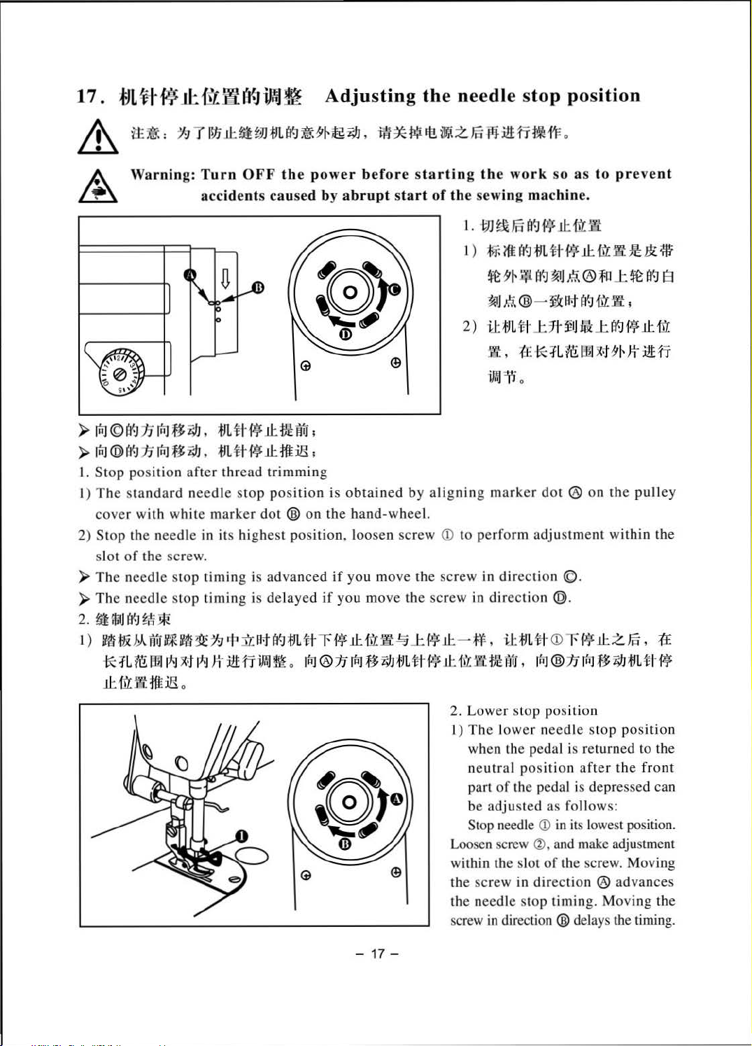
1.
I)
2) Stop the needle in its highest pos
)>The needle stop
)>T
2.
l)MfiMMaM
tt
tJ:
:
:'19
Tllti
11:
~
~JJ
m
(f)~
Warn
in
g:
~:~:e~~:at:
M ©
IY'.!
17
rfiJ
.n
~
J. m ~
riT.J@t~
St
The
cove
sl
~;fjlj(f.J
:n
rR:J
.nl;f
J. mtt~ll:tt:ilS;
op position
standa
r with w
ot
of
the screw.
he ne
edle
~fi
*nM~~m~~illfi~M
11:
-tto! m :ilS
aft
rd nee
hit
stop
*
~ ~~~
o
H¥
11:
er
thread
dl e stop pos
e marker dot
timin
timin
trimming
g is
advanced
g is de
M~mtt~~li:~W~~
tf!
ition
®o
lay
o ~®
5
ffii
5'
1-
18}
~
,
i1f
*
f!li
El!
tiff-
Z.
Fo
r'l
:i
t.H'T
1~d'F
o
::~;::::;:::a
:
~a
~t::
:
0
1.
1)
2)
s
~~
i~~o:~
WJ
~ ml'l~
~lll'f.JfJL#
~5'1-J!li'J'.J
~J
t.\
i
J:
fJ
11.
,
~ii
® -
L 'it J:
.ft
~
o
cs
h~na:
i'f
.u:
m
~
.ll:tt~:ll&:*
~~
F.i.
®lll~~
~'3c
lt-tfJ<){\t
7~ ~
IJ
Mi
:t
Ut1t:mx--
;
is
obtain
n the ha
ition
, loos
if
ed
if
you move
:n~n~mtt-Wkm~m~
ed by
nd-wheel.
en scr
ew
you
mo ve th e screw in
the
Wll:
alignin
scre
g marker do
CD
to perfo rm adj ustme
dir
ect
w in directio
- ~.~mttCD~
t®
ion ©.
n@
.
Wll:z~.~
.
~®:n~n~mttw
to
prev
JYt
~
;
J:
I'J'.J
i • .ll:
J
5'
1-
~:ill:
on
the pulley
nt wit
hin
e
nt
I'!{]
B
1ft
fi
the
2.
Lower stop posi
1)
The
lower needle st
wh
en the pedal is returned to the
ne
utr
al position
part
of
be a
dju
Stop needle
Loosen screw ® , a
withjn the slot
the scr
the needle stop timing. Moving
screw
- 17 -
ew
in
directio
tio
n
op pos
after
the
the pedal is depresse
sted as fo
in
direction
llow
s:
CD
in its lowest position.
nd
make adjustment
of
the screw. Moving
® advances
n®
delays the timing.
ition
front
d can
the
Page 21
18.
®~*iWJifnbifli
Oil
cheak
and
addition
~~1JO
&
A
.
r:t:
~
:
79
Warning:
T
l!1i
1l:Jil
Turn
accidents
~J
1JL
OFF
the
caused
~
~
jf-
pow
~
i#J
,
er
before
by
abrupt start
i1f
*~Itt
W1.
z
J5
¥J
:ilHT
starting
of
~~~~!J.J1!Lat,
iii!
m-
m-
ilb
1
J.iH~HJL
;t:JU~
2 .
:!Ill*
the
work
the
sewing
im
i'l
~
n:,@
0
1:1:\
ratE
~
rlil
it
1iti
, ~
~
9='
af.J
iii!
M
J::
af.J
IN~
'®~~M~RJ
it:Ji!:~YE,@,
!ti!T~;ffiJ1&~%ii!H~J::~~IjJ.l'
~
0
7lf
7f-
iJH~
JfJ
~~!J.J;j:JL'
E
r~K;tc$,
IN~
~
iVdt
o
so
as
to prev
machine.
i1f-~!N~;t
,
litat
~
;JJu
n:,@
t:t
liH~ ~ ~
~31
;J:JL
1:£
1t
JfJ
ilH
~ ~ ~
%li
~,'fkattE*
tt<OO;tT-
~
~lj~ 87lf7f;l!i~~1itl
~!N~·~~!fh'&~ilil
"P
af.J
l1Jc
i~
:¥€
ilb
;tT-
RJ
~
1k
-
1!f~1ftitRJlW
ilH
:ii:
1t:,@
rf'EJ
ilit
ilH
E
ent
-i;!H~%i
af.J
rf'EI
;JJn
YE,@
Bt
,
IN
~
,
:iii
ii
a~t
~ ~
~~%iiJ'EJ
~lj
'ilf
~
~
1!J!
]l
o
t~
f=€
7t
1~
,
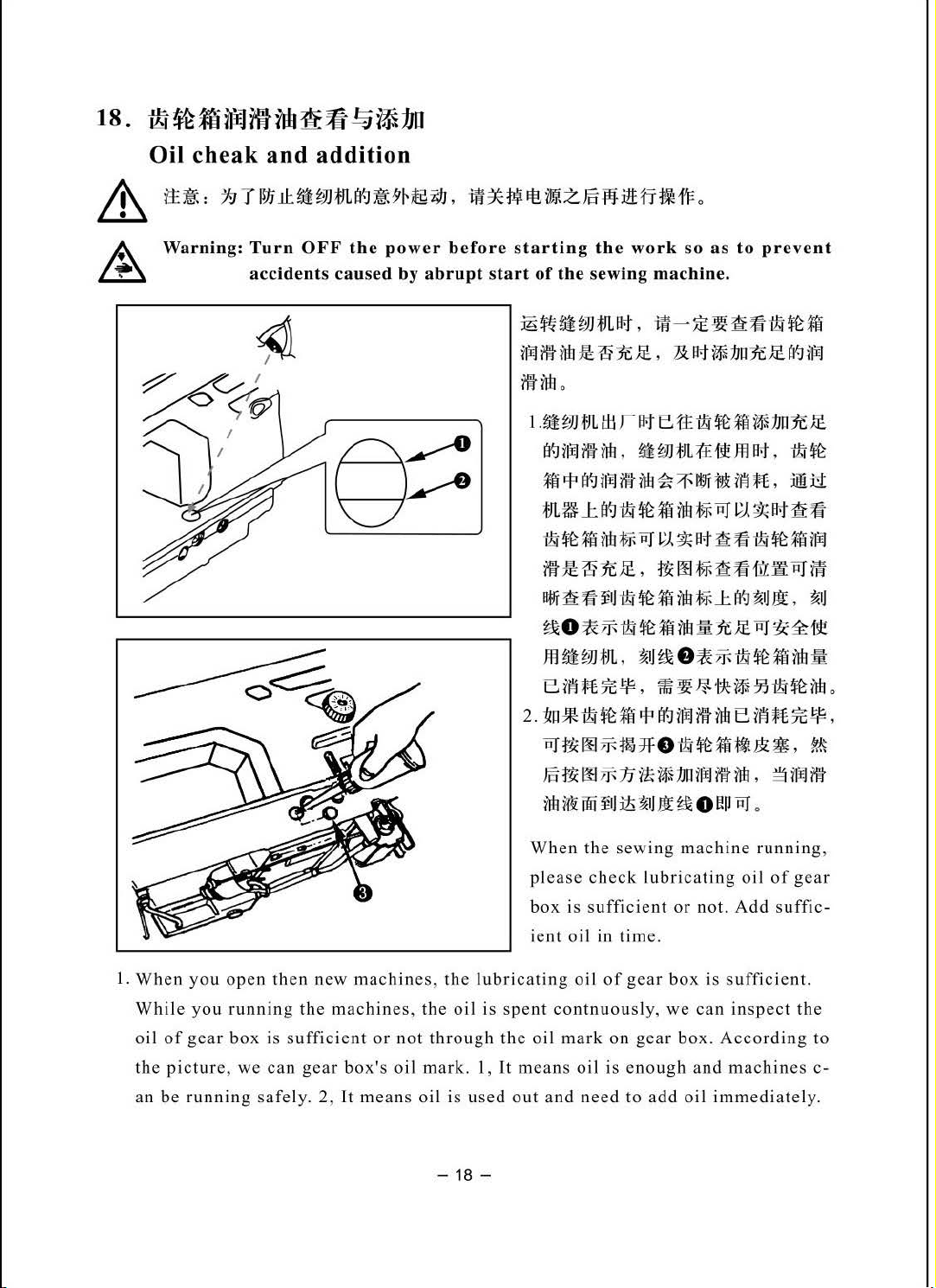
1.
When
While
oil
of
the
pictur
an
be
you
open
you
running
gear
box
e,
we
running
then
the
is
sufficient
can
safely.
new
machines, the
machines,
gear
box's
2,
It
or
not
oil
means
the
oil
through
mark.
oil
is
-18-
When
please
box
ient
lubricating
is
spent
the
oil
1,
It
means
used
out
PJf!.i:007f-mJF
J5
~
oo
7f-
nn
rr!'i
oo
fiJ
the
check
is s
ufficient
oil
in
oil
of
contnuously,
mark
oil
and
need
o·~~%i~&:~,
:n
tt
~
11u
rf'EJ
ilit
:iis
~IJ
It~
o
erJ
sewing
time.
gear
on
is
enough
to
machine
lubricating
or
not.
box
we
can
gear
box.
and
add
oil
is
sufficient.
According
immediately.
ilH
,
~
RJ
o
running
oil
of
Add
inspect
machines
r&
rf¥1
ilit
gear
suffic-
the
,
to
c-
Page 22

2. If
then
the
oil
add
is
lub
used
ica
out,
ting
please
oil, it
uncover
is
ok
when
the
the
rubber
oil
is
plug I of
up to
the
gear
box(note
scale 1 of
oil
the
mark.
picture
),
19.
&
~
2)
Loosen
if:titf..JiJJ~
~i":
:
:79TWJli::~;.JJtJ1ff.Jliit.5'~jfgi;IJ,
Warning: Turn O
accidents caused by abrupt start
adjust
screw@),
Adjustment
FF
the
power
and
adjust
the
of
the pedal
iW*tlii~mzm¥J:l£t1'ti~o
before
length
starting
of
of
connecting
the
work
the sewing machine.
1.
a*
I)
fRJ
~::k
CD
,
H<6l
2.
m~ff.J1ftlt
1)
iJWi'J:itf~Ha<:l*It
~~~ff.JJfJJto
2)
rrr~i!n111~~n
H
<6l
1. Installing the connecting rod
1) Move
left as illustrated by the arrows
so
that
and
straightened.
2. Adjusting the pedal angle
1)
The
adjusted by changing the length
of
the conn
rod
so
l-r
ff.J
~ ~
ti
1
P:J
~i;IJm~i!n111~
iJ:
fb
:it
t£
nlt-
1l~o
:ilHJ'
iJWi'J
pedal
Q)
motor
connecting
pedal
tilt
ecting rod.
Q).
as
to
prevent
fliiJ
H
CD
fll
Ji
e
P~
® ,
~i;IJ:i!*
o
to
the
right
contro
l lever
rod
Q)
can
be
freely
~
~J
r&
or
CD
are
-
19-
Page 23

20. •:Hi
lift
Pedal operation
~----
~
I @ 0
I
I
I
I--
• I
I
-k!$
::
I I
~
0
1.
~
tlii
.fl4
~.&
W!
~
I)
rt"J
HIJ4£~/ll·tlli~f~ia!~W@;
2)
.flj.~~ttiVJ!ll~:t&~~:i!~~JJ
®;
(
@.:fl'
*~€,
i§t~ 7 ~
ff~~~*z.m~~:i!
~iill~
~
*Rffia~~-mftR~M.
•m~~~©n•••••~m~~~.
~
:!Ia
ft!
(f.J
~
I
i5/J
f~rj
ft!
9='
,
t~
~
M
iWi
:iY!
~ ~JJ
Ii
.X:
f~
i~Hll
~JJ
~
rtt
~JJ
m ·
oo
;l
tJ:t
t~
~t. • J~&
~
~;.)]:tiL?-?
1. The pedal is
I)
The machine
pe
dal@.
2)
The
pedal
high
3) The
* If
you mac
1!:
machine
@. (If
speed
after
machine
{JL
~ -
operate
runs at
runs at
the
automatic
it
trims thr
hine
is
r-
Itt
?it~
d in the followi
low
high sewing
completes
eads
provided
a~~~WM~OO~~--*~·
M fill&
1ft
liD
@I
rtJ
€ m
9='
iz:
{lL
Z.
J§
,
sewing
reverse
reverse
when
with
9='
iz:
{lL
1:1
• M
~
m m
:flo
:lit!~
ng four
spee
speed
feed
feed stit
you
fully
the
Auto-lifter, an
-
i!t
.!i!IJ
;t:&
rt!
~
1TH~
7H~
d wh
en
when
stitching
depress
~m&&•M•.
~
~HJL
ffrJ
ft! tfi
>K
€
f
~
J.l:.
~JJ
:tJL:t~~fiiJ-~J
re
~
:tiL
tH·t ,
steps:
you
you
ching.)
~
•
m
jC
0
ttl
tt
Iff
Ill
lightly
further depress
has
the
depre
been
back
addition
preset,
part
step
-~ M
ss
of
:t&
the
front
the
front
the
machine
the
pedal
is
given between
o
part
part
@.
~ff
of
the
of
the
runs at
the
machine
the
is
~
If
at
~
The machine
the pedal
~
The ma
neutral pos
~
When
depre
sto
p and
back part
actuated.
you
res
seam start, the
the
ss
of
et
the
will
immediately
chine
will
ition
machine stops with its
the
back part
thread-trimming
the
peda
l ©,
and
pedal
to
its
neutral
machine stops after
perform
completely
immediately
normal
following
of
the
pedal
perform
after the
step.
The
if
you
further
position
it
completes
thread
high
needle
once.
trimming
or
low
thread
machine started
down, and
-
20-
pre
sser
foot
depre
during the
speed
trimming
goes
ss
the back part,
automatic
the
rever
even
if
sew
ing.
even
thread
if
you
up
se
you
if
trimming
want
when you lightly
the
thread
reverse
feed s
depre
you reset
to
bring
titchin
ss
the
the pedal
act
feed s
g;
back
ion.
the
depress
trimmer
titching
part
of
to
its
needle up,
Page 24

21.
ltiffim
One-touch
~mff
Util
type
reverse
feed
stitching
mechanism
1.1t.mn¥*
t)~~***ffro.•wm~~••~
2)
1£
#(
~
1¥-J
at
tal
i!H1'
f!tl ~ ,
3)
-=F-:f~*~R
P
~79IE
rliJ
.;JJ
o
3)
The
machine
2.
**A'·ljfijJj(
&
A
1)
2)•re**ID~Uz:Kfll
1)
2)
it~
Warning:
**CDfi~f=iUl:!filJ
Switch
In addition, when you desire to lower the position
in
the
back
ill
resumes
Height
:
19
can
of
of
T 1
!15
.Jl.
Turn
accidents
be
used in two
the
machine
norma
l feed
stitching
the
switch
~JHJL
ft9
~
5'Ht9
OFF
the
power
caused
~1:4!#1
~
~M.
head
by
1
-~~•wmww~~~•n~.
positions
and
191
, l#
before starting
abrupt
by turning it.
lower
1. How
1)
2) The mac hine performs reverse feed
switch
to
operate
The
moment
machine
as
long as the switch lever is held depressed.
the
moment
;Yd¥
It!.
start
of
of
base
switch
performs
the switch lever is rel
tmt
z
!a
the
sewing ma
switch
®.
lever
reverse
fll
:ill:
fi
the
work
CD,
loosen setscrew ~ located
CD
is
pressed,
fee
d stitching.
~
1
1"
o
so
as
to
chine.
~~**•®o
st
itching
eased
.
prevent
the
-
21-
Page 25

22.
f£ttff
Wiper
&
A
1±
~
: h T
Warning:
WLLI:-Jl
Turn
accidents
;.]
OFF the
fJUI~
~
)'Ht9
i9J , i13C
power
caused
by
before
abrupt
P-i!
It
imt
Z.
Ji5
.pj:
:itt
starting
start
of
l.
r
o
2)
3)
1.
according to the thickness
the
the
sewing
1£
~
;ff
(f.]
ttH.l
ff
JIJ
17
¥R
:itt
rn:JIE·~
~J
1.(
CD
JIH£
~
~~~~~tyQ),
$
*'J
;fJUt
~-ftJflt!{~;ffat,
**
Positioning
Adjust
the
fi
ti
1'F
o
work
at~
fi
1J
X1
so
as
to
prevent
machine.
1tr
~
-m:
:m
m w ;{fi
iftl
11
rn:J~i9J~~.
ifUJL%
tr.J
~IJ
*4
at~
JJ
il:~~s
.~
a>
o
;ff $ ® ffU!H.l ;ff , M
1~~5~ff(f.J.ifJ!!
r.p
,c,,
at~~~
1iJ
t~
~~
1iJ
ii3CP-i!t£~;ff
the
wiper
position
of
the
of
the material
wiper
It
Ji5
1
mm
~
tT
;
-22-
sewn.
The
adjustment
follows
1) Turn the
2)
3)
:
hand-whe
direction
marker
with marker
arm.
Adjust
flat
of
the needle to 1 mm. Tighten wiper
adjust
pre
@).
When the wiper is unnecessary, turn
wiper
of
dot
the
part
of
the
screw
ssed and
switch
rotation
CD
dot
distance
Q)
fixed
procedure
el in the
on
the
Q)
on
wiper
so
that
by
@ OFF.
normal
to
align
hand-wheel
the
machine
between
and the
the
wiper
wiper
is
as
white
the
center
is
collar
Page 26

23.
tJLtJ-
!:§~f£®=*~
Needle-to-hook relationship
Warning:
1.
~~~~.~#ff~~-~~.
2.
1iftJ~ti·ff~
l)~mDB#~,
~
{ft~~tr
2)~mDA#~,
~
1iL
~;
tr
3.
1iftl~-~{ftft
l)~mDB#H, -~~
Turn
OFF
accidents
It:
~#ff~~~~M®~$#ff~MW
00
;
~#ff~~~~M©~$#ff~M
CD
o
:
---~{ft-tr,
the
caused
pow
er
before
by
abrupt
Mfitr~#ff~•tt•~•uoo;
starting the
start
of
the
®
W®~
#~~~~.
work
sewing
~~-.
~-.
~#ff~~~~~~~~~®
5C1/t#ff~··® ~~~ffil;
2) 1
4.
machine.
MfiW.#ff~•tt
MfiW.#ff~•tt
tmDAttll>t,
-~{ftt,~tr,
1~
t-1
· tr
M@~lt#ff~MW®~
~~;
t£~~~:1\~~,
1;J
~ ~ ~
•C.\
, #
o.o4 ~ 0.1 L:kf.l)
so
~
t£
5C1?l
1=3
as
to
prevent
Wt~.=UW
:tf:~~~~'
~~
~ ~ ~ ~u
~--A~
:J:JL~H
~)
~
I=J=t
W •
~ lalfl-~
19
~*,
•~w••~•~•tr
~~
1.
~
~li:~l~t:7.c*,
2.
••tm~~£~.
;m[i'iJ~!W-'%o
l.
Turn
the
loosen
2.
Adjusting
1)
While using
bushing
hand-wheel
setscrew
the
needle
DB
®,
then
to
bright
CD
.
bar
hei
ght
needle
tighten setscrew
, al
ign
the
needle
:
marker line®
00
bar
.
-23-
down
with
to
the
the
lowe
bottom
st
:
!'13
1
~jjt:;J.c;J
..
' ~
1!1b'l·~;
~51~W~#;
fl!f
point
of its
stroke,
end
of
needle
bar
lower
o
1:i!!m
and
Page 27

2)
Whil
e using
bus
hin
3. L
ocate
1)
Whil
e us
mark
er
bu
shing
2)
Whi
le using
marker
bushing
4.
After
making
with
the
between
Caution:
1.
If
the clearanc
value, the bl
will
resu
2. Use a ho
DA nee
g Q), then
the hook
ing
lin
Q)
lin
Q)
center
the need
lt.
ok
tighten setscrew
position:
DB
needle
e ®
on
.
DA
needle, loosen
e @
on asce
.
th e
adjustments mentioned
of
nee
le
e between the blade
ade
point
of
the same
dle, align
, l
oosen
ascending
nding
dle
® .
and
the
hook,
of
hook
part
marker
the
needle
the
needle
Provide a clearance
will
No.
line © with the
CD
.
three hook set screw,
bar 2 with
three hook set
bar 2 with
in
the
then
securely
point
of
hook
be
damaged.
when
replacing your
bottom
turn
the
bott
screw,
the
bottom end
above
of 0.04
tight
and
If the cl
step
mm to 0.1
en
setscrew
the needle is smaller than the spec ified
earance
hook
end
the ha
om e
nd
of need
turn
the hand-wheel,
of
s,
align h
Omm(reference valu
s in the
is larger, stitch s
with
a n
of nee
dle
nd-wheel,
le
needle
ook
blade
hook.
ew
one.
bar
and align
bar lower
bar
lower
and
align
lower
point
kip-ping
<2)
e)
24.
~ntr.JJ!Jflfj~J!~
Change
&,
A
tt
~
Warning: Turn
E)
Moving kni
E)
374JJJ
of
:
1:1 7 ll1i
accidents cau
counter
11:
fe
C.if
fll
r3J
m
~W
OFF
the
G)Cen
e mtt.P·t'
JJ)
knife
~
:Yr
~
power before
sed
by
ter
of
need
(Parallel
i;IJ
, m
*~It
abrupt start
0
~
le
knife)
i1ff.
z
.15
w.
starting the
of
the
sewin g machine.
iJJ J J ~
F,Jr
~
Wf
~~:fit
l)
te!.fim
ZUf.J
Jllt~lf£t'I~UoJ'
2)
ttli:®:tJ
1±
~ : m m
-nrt.
o
.i1Hr
rlHI:
o
work
Jlf
0
~
so
as
to
prevent
'I:
R B·j,
·
rtf~
lf. 'till
00
©
~
~
JJ
CD
,
?~
.15
IE
TdfJ
A9
JJ
fttJ~~ifr~tt*~ltti:
;fi
@
:1J
lt.:J
n
i;IJ
,
iiJ
~
*
~;
~t.:~n~.
ll!if
~ n
-w~~~
n·t
i't!f
1±
~
1iJf
.
•
-
24-
Page 28

When the knife sharpness has
in ©
.a
nd
properly
If
the mountin g position
1)
mounting position, the thread length
2)
If
the
mou nting position
accordingly.
Caution: When re-s
hand ling
reinstall it.
harpening
of
the knife.
of the
is moved in
the kni
deteriorated,
counter
knife
after
direction @,the
fe blade,
re-sharpen
is moved in
thread trimming will be increased accordingly.
extra
counter
direction
thread length
special care
knife
CD
@ from the
will be
must
be
taken
as illustra ted
standa
rd
decreased
on
the
2s .
J£
Change
&
11
A Wa
25.1
25.2
!M)i::JJ
?JJJJ
n
f;O
~J n rl'~
of
~
:
19
T
~Ji
rnin
g:
Turn
ac
JiJf
If!
counter
11:
~
~JJ
;tiL atJ
OFF
cidents
caus
~
J!~
knife
~
~~
the
power
ed
oren)
and
moving
~
i;IJ
,
iii*
tt.i
before
by
abrupt start
1.
2.
3.
*
~~nfE
~~JJff.JrvJ-!1/Jt~
~JJA~•
1.
2 .
3 .
4.
5.
6.
7.
starting the work
:iDe
fiiJ
m
~
~~~n
f'~~~fi
lfR
r:t:JU-1-
J=IHfl
ffi
n~
r~
tJii
t'«
n
•i;IJ=t-~
:iDe
JIJ;tJ
L
~
~~~~~n~m~~~~~~m®~¥~
f!J
~fi0tf.Ji!Lfl
f'~~~fi
knife
It
Wit
z
Jfi
of the sewin g machin
0
®.
mr~~~~~®o
®,
~Iii
ttftft:ffiU
.
~oo~nM~®~•~~~JJ0o
0
1
tli
=f.
ttl
CDr
21-l.
• •
#ff~*¥Q~ff.J~~o
o
0[2
1-1.
(Rotation
:jiJ
:ilHHNd'l=
IOI~JJ0o
:
ffiil'f<J~Il&~~:ill:fi
i8Hli
Jl~
~~
~!.{
J§
0
ti.{J§~:±I~JJJ®o
o
so as
~
o
J&
ill
~-
knife)
to
prevent
e.
o
:
:ffi
0 0
*
~~
n'lt-
i#~Jm~
-
25-
iiii
P9.fl;l&.
~!it:i!Hr
o
Page 29

26.
!)Y~~IHf.J~~
Adjustment
Oren)
of
trimming
system
(Rotation
knife)
Warning:
Turn
accidents
OFF
the
power
caused by
before starting the
abrupt
sta
rt
of
the
work
sewin g machin
so
as
e.
to
prevent
<- )
!Jhlb!!!
~~1
~~ffi·~~~••®
111i m 1lf
~•n®.•*~•••~.
!\t!j.iJ
~ ~~ ~ CD-&~
·-~~®.
<=)
F9JJ
ffi·~--~.mS8~~Mfi~CD~S~illA~M~~CD
1!!1
~L
Au~.fil.Ei~JJJ
8~JJ-~ff®~~JJ®~fitrfil.Ei~JJCD~?JJ$•~.~JJCD,
~
n
®m
~
fu
~t
a9
ir.I
i'l
~HJJ
~JUf.J
CD~~
·
(:~~
~ ~
J: ~ ,
f&:
~H
~•~.
ff
:ilUJT
~ 8 ~CD
t
ff
~••®a~
,
-fit!
lJ!I
~ 8 ~CD
~~~~8~CD&•~-~.
J'
~JJ~J!tit.li'l
~
~1
J:
CD?JJ
a
i~
~ , ~
i'l m
n
ft!!ii
ff®~rwrw
P
~~Pftl-€i-0.2
l1!
tm
f*
-
0.5mm.
iiE
:££-'f.
-
M
liHI£ f!l
~~••®~~m~.
~
1!!
:mJ:
1
~~
, l
Jl·
lfli
5 mm
IH
1ifE
ll;f
•
!)J1
.•~~n®.~~~
:tl
trfil
00
Ej
iU
~
ti:
~ffil
00
n
~J
JJT
M
26
-
CDt&t9Y
ilo*~'HI®-€i,
1M'
~m
!JJf
ttrr
M
2 o 3
~1
~1M' , ~
til~
, ffi
=F
1G-
A
W~8~~
~ 8 ~
1
1i]
~J:t
CD
1:~
0.
5 m m ,
n ®
MEt~~~®,
•
Page 30

27.
~t-l-7fa9
1Wi
ll'"f~$4Jjt
Height
and
tilt
of
the
feed
dog
Warnin
J!j[~
lmm
g:
Turn
accidents caused
0.75
- 0
OFF
.8S
mm
the
~
power
by
abrupt start
befor
c=:
e s
tarting the work
of
the
sewing
l)iO.
ilit&~;ffi;fll-~~1*
~a~~HL
l.
:iti
~!M
I )
2)
so a s
machine.
:iti
*4
?f
75-0.85mm(JJ-1S
*4
7f
a~
t-r
f~
tiL'lf
<D
~}E~UQ>i;J.lit?f~~
{l7rl
•C
Af)
a>
m"-;t~JJ~i;IJ
ii~
PJ
I;J.
r&
to preve
~
1./i
It
~
~
1
ifiJt~Ti~
ri11J
~
fa
ftm
ltlrj:j!;j
iJI
Ti
a{]~
1E
"-;
<D, ®fW~!1i.
~ * ~
?f
nt
1./i
tl:l
~t
Yill
mm) ,
-*4
~
{liB
•I)
n ® ,
a{]
1./i
It
at!
W:i
faft!n#-41t,
- 27 -
3)
:ff
*~m~~i';/Jn
~®at){tjji~~:*~ift$~
4)
~!Mm, ·r.H~t-rt~~t;n
fr~~)'Eo
a>
{irl•
t)Wf
®
rw
!1!9!
(iW'1:£ft{I:
~~~rt-r
~
JEJ ..
;
n)
lllJ
~
;f'f.
l?f
(D,
Q>
,
Page 31

7:1:~:
··~•Rm-~~m~m*•~mM~~M~•.
m
Wi
tltHI'-J
tl'l
*
i2l
~
o
2.b•~~mmwzm.~M~~~~~wm~.•~~~••
tHf
~:@
~
i
:ll
)\1 o
H
eight
of
the
feed
dog
is
surface
the
1.
1)
2) Heig
3)
4)
Ca
1.
2.
by
0.75
material
Adju
Loosen setsc
screwdriver.
For
to
the
After
state
uti
on:
If
the
Be s
Movement pos
of
the shaft.
movement position.
to
be
sting the height
rew ~ in feed
ht
and
tilt
the
relation
figure on
the
adjustment,
that shaft
ti
It
of
the feed
ure
to
adjust
At
to
0.85
used.
of
between
the
s
CD
it
ition
this
adjusted
mm (1 mm
and tilt
bar
the
feed
the
left.
securely
and
Q)
are
dog
is adjusted with
with
both
of
the
feed
time
, l
oosen setscrew Win
dog will
rotating dire
for
of
the
driving
tighten
pushed
shafts.
dog may
so
that
Hea
vy
feed dog
shaft
change
ction
the
against
one
be
mMw~~-~~~~.~~-
the
feed
dog
protrudes from
type).
CD
setscrews.
shaft
shifted
Adjust
and
setscrew
by
turning both shaft
of
each shaft
(Tighten setscrew
the
hand-wheel side.)
only, the height
depending
feed
rocker shaft
the
height
@)
and tilt
-~
m
~-~~nw.~m~
the
throat plate
in
accordance
in feed
on
of
the
the
arm
bar
rocker
s
CD
and
of
feed
s
Q)
feed
adjusting
00
and
Q)
bar@,
and
dog
adjust
shaft
wi
@)
in
changes.
position
~
with
Q)
th a
refer
the
the
28.
&
1.
2.ft~~~8~CD.a~~~I~~~~W"~o
~
~
~tfi(f~
it~:
Warning:
!....
,
-
~~~~8~
~
M
in.l
jD{ff~~m.m..
reM~AAM~~-
fliJ
( + )
flil
( - ) n
ff1j
~
Adjusting
19
7 l
lfi
JI:~~JJtJLfl~~j~Jm~,
Turn
acciden
CD
~~~~-.-~~~~~M~~W"OO
W
~~:riPd
~
:1J
~:
rrr~ta~8~CD~Wi~~}E~tr~;
Q)
:15
flil~~ffi~8~
fl1l • i;IJ
1#
the
OFF
the
power
ts caused by
~-~~-~~~
CD, J:rta~~IRJWB·tlal~tJb
~ 8 ~
CD
, J: r
feed
before starting t he
abrupt
®
ta
~
-
28
timing
i1f~~lt!.
start
r19
~
-
itiitZ.mfl}lttft~
of the sewing machin
o
w"
1
a1
~ ~
0
work
1
'F
o
so
as
to preve
e.
nt
Page 32

~m:-&Mm.•re~~®~~~mm~~
The
feed timing can be
changing
eccentric
How
1.
Tilt
loosen two setscrews
cam
2. Turn feed eccentric cam
the feed timing.
Align
driving arm with engraved
@)
on
);>
Turn feed eccentric cam
direction
timing.
);>
Tum
of
Caution:
the stop
cam
CD
.
to
adjust the feed
the
sew
ing
machine
CD
.
grad
uation ® on
the feed driving shaft.
of
( +
)-tlncreases
feed
eccentric cam
(-)
-tDecreases
For general use, use the machine
with the engraved
changed
position
a>
in feed eccentric
CD
the feed timing.
of
timing
head
CD
to change
the
feed
marker
CD
in the
the feed
in
the direction
marker
by
feed
and
bar
line
in
line.
o
the state that center
of
graduation ® is aligned
29.
•[ijt*JL~
Thread
&
7£
A, Wa
~
:
rning:
tension
19
T
l!1i
.t1:
Turn
accidents
release
~
;.]]
tJL
OFF
~
~
the
caused
releasing
~HI:Q
i;JJ
,
i~
pow
er before
by
abrupt
~m~~•~m~.
-
t!!.~t~~o
~li~JR$.
l.
~i~177t
I)•~•wm~•~.
3f~~~trCD;
2)ffl~trCD~~~~~~~~<bl~~L~o
~~ffi·M~SB~~~S.
t~!M!!
-
29-
mechanism
~W-It
start
tl
z
J5
-Pl
ut
rr
~
11=
o
starting
of
(JJ~~fi!fi~m
the
work
the
sewing
fffi~s~JJ~~1t)
so
as
to
machin
~~~~~~•~m~
e.
lf~i;IJ-~
BSJI:J4!,
m~~~-·~~~~
ffiS*JJ
(
,R1:£"W~M1E~B;tt~~)
prevent
iJ:
E
~~
Page 33

~m:
without
sewing. (Ev en when
knee
1. How to rel
1) Remove the
2) Fix screw
Ca
30 •
~n
~ ~JHJL
By
mean s
slac
lifter
, this mechani sm
@ us
ing
isk
doe
d
loosened.
ution:
Do
thread
bottom
frlbi!J.li
m ~mw.
tl\ ~ R·t
of
the
kening
ease
cap
a hexagon wrench.
@ on the top
s not rise even when the
(The
thread
not
use
ten sion rel
position at the time
JJ1P
Micro-lifting
Rn~~~-~~--~~~~~~~~.
1m)£
1£
S:
~
1lr
l!i:
o
thread
the
in the
~
ten sion
the
sc rew
needle
press
thread
er
can
machine
of
thread t
tension disk rises
CD
at
ease changeover plate.
*
mechanism
release
foot is
prevent
head
ension
presser
any posi
of
releasing
tension
slightly
the
thread
and
loosen thread tension release
release
foot is lifted,
only wh
tion other
delivery.
of
the
mechanism, s
even
when
lifted
ten sion from bein g
changeover plate
en
The
presser
~
ewing
th e presse
at
the thi ck overlapped s
and
the need le thread tension is
thread
tha
trimming
n the top or
screw
has
r foot is
chang
Q)
bottom
been
foot
~&w~nRmo
can be per
ed.)
changeover
. The
thread
is
performed.)
posit
factory-set
lifted
ection
ion f the
formed
dur
by
screw
tension
to
ing
the
not
the
& tt:
A
~
Warnin
~
:
19
t
g:
Turn
accidents cause
Appro
x. 11 mm
i~11mm
IVJ
.1l:Ji
~JJ
~
~ m ?-~~
OFF
the
r
pow
d by a
Z9J
,
~
* ilii
er b e
fore
brupt start
Q
0
J:l!tliitZ.
st a
rting th
of the sewin
~ m
iiJ
tvH~io
~-M:fT~~;'&HffiJ~t!fi-~'-UCD,
ifni~
71-~nrN.
~~:
not
~
JHJL
~m::fttJLft:Jm:fl-
fm)J~~ijij
m
~itt
fT
t:
¥d't=
0
e w
ork
so
as
to
prevent
g machin
~lfit1t~~
~-r· J.lin~JtJ!fl-
~~1~~.1SHililfli,
1-E
ij-~
1lJ:
®
¥11
~
fl
~
r~.m~~~HJ:
~i'iJ.iJtl41tJt71-mtt.J~Rm
•
i:t'1
tE-
~ n
t:i
r.J
I I m m
0
e.
~
~95·~~*4aot,
~u CD~-~
~~~*4~
:fT
;f~
~
:1-R
~ ~
I -
.1S~
~
iJ:
ffi
Jtl4l
V\t
ii
~
®
l'lil~.
CD
f@i
J1r
iJl
~
¥~J
lt
~
((.]
1
rr
:'lt o
~
ilk ffi
Fn~~JJ~(I'.J*1fi
-
30-
Page 34

When sewing velvet
reduc
ed by
using
Gradually tighten screw
adjust
and
Caution:
31.
the
presser
fix
it
with
nut
when
the
screw
If
working, s
<D
the sewing
~OOfJI.f.JWHE&iiiJIH:~$~
Caution
or
screw
foot
to
@.
presser
so
that
machine
uf
ficient
when
the like which is fluffy, slippage
<D
for
presser
<D
for presser foot micro-lifting in the
the
position
foot
it
is
higher
is op e
feed
carrying
foot
micro
where
micro-lifting
by
approximately
rated
in the
force
cannot
or
placing
-li
fting.
it
is fin ely lifted until it
mechanism
state
be
obtained.
of
11
tha
the
1.
~
is
t th e
material
not
mm than
sewing
tM~.n*
il!f
or
damage
state
that nut
matches
used,
adjust
the
micro-lifting mechanism
of
<1)
the mat
the
sewing
machine
~
.lffl
III
~
~~
¥-¥
,
material is
is loosened,
eria
height
machine
El3
W>l
A
:>IH:fR
of
is
l,
.
\
r:~:~:
2.
~t
3.
two persons as shown in the figure.
Caution:
4.
thing such as screwdriver or the like
on
machines
ll!f::f~1~7fi
1tc~
~
;>JJ
tJL
·
i~
::f
~
1E
t"«
~
;>JJ
m
a~
itt!,
How
to
machine
Carry
the s
Do
wheel.
Caution
sewing
Do
not
the
place
is
when
machine
place
set
Et~H~*m~
It-t
fl':l
1±
~
$
~
JJ
~
1.F-
.n
0
carry
ewing
not
hold
placing
any
where
.
the
machine
the
protruding
the
W 1ft
!iii
fi
J
Jit
sewing
wit
hand
the
sewing
h
-
-
31-
Page 35

1 ,
;f;JL
1*
if!H4
MACHINE FRAME & MISCELLANEO
4
US
COVER COMPNENTS
.>
54
20
-1-
43
L42
51
50~
b
41
.1
Page 36

Jf;%
REF.No.
flf
Part No.
217GR103
I
2 GS300-8
3
GRI006-8
4 GS300-8
280GRIOJ
5
217GR109
6
7 217GSI07
2!7GRI05
8
217GR113
9
217GR104
10
11
2!7GSI03
GC5580·D3.
GS338-8
12
GC5580-D3. 1-9
217GMI01
13
Zl
5580-5-D3. 1-
217. 1-23
14
GWI67/4-8
15
280GOIOI
16
17
280GRI02
18
GS300-8
19
240GBIO I
20
GR583-8
GR604-8
21
GS313-8
22
217GSIOI
23
GS373-8
24
GR724-8
25
GS316-8
26
27 GR603-8
GS313-8
28
217GR 106
29
217GRIIO
30
217GS102
31
32
GR605/I I-8
Zl5580-5-D3. 1-2
33 217GSIOS
218GDI53
34
35
218GDI56
218GDI57
36
37 218GD152
38 218GD I
39 218GDI54
40
218GDI
-13-
~
**
Fo~t&
m~w~n
Jt!.~ffit&
tt~fflmtf-'~~n
tt~ffll!ib'>ii
ttlllit*
~)
12
+~~~ii!'-'f:B
ttlllit~
<l>
8
~ff
J::~tt!Jlll*
tt!Mt~
<l>
13.5
itt&'-'f:B
1-8
itt&~t1
~t&'-'f:H(
tt-t&~4\tr(
t'tt&
2 tt·t&
1t;f
ttt&~!l.¥1=
mit&~
Ifiit&
iiiit&~tr
illit&~i'fli)l!l!
i'fiit&tt!!BC~
ft~~
ft~~flil~~l1
iitrx~~~n
IIFHll:f:in
m1
~ ~iJ
15~~
;(j~~~~~B
~~it'f;t~
"lti~~~t~
·
r&~~IH'&t~tr
~~m¥1=
~~ffif!
ilbi!llflil~
f*~;JEt:~llJt&
*~**'~*
~@.**
~~+.'f:tr
55
~@.**x~
f!fd
51
"*~**~
-
*:ik)
-!¥
:ik
)
~~ifi.J;f)
J;
~tr
ftf:ln
W\'i
.!t
~
~~tr
l:
~n
~7f*x~41l
l
Name
of
the part
SIDE PLATE
SCREW 3/ 1
CORSHOLDER 2
SCREW 3/
THREAD TAKE-UP LEVER COVER 1
RUBBER PLUG
SCREW 11/
RUBBER PLUG I
CAP
RUBBER PLUG 1
SCREW
SCREW
SCREW
SCREW
THROAT PLATE
THROAT PLATE
CEAR BOX FLOATERASM.
SLIDE PLATE ASM. I
FACEPLATEPACKlNG
PACE PLATE
SCREW 3/ 1
PLATE I
RUBBER PLUG 0 = 12
ARM THREAD GUIDE
SCREW
SCREW 15/
SCREW 11/64- 40
RULER STOP SEAT
SCREW 15/
ARM THREAD GUIDE A
SCREW 11/64- 40
GEAR BOX PACKING
GEAR BOX COVER
SCREW 3/
THREAD
THREAD TENSION ASM. I
SCREW
SAFETY
SAFETY
SAFETY
SCREW
SAFETY
SAFETY
SAFETY
6-28
16-
28 L= 9
64-40
11/64-40
11/64-40
11/64-40
11/64-40
6-28
11/64-40
64-28
64-28
16-28
TENSTON
SWITCH
SWITCH
SWITCH
SWITCH
SWITCH
SWITCH
L= 9
D=
12.5
L= 4
L=7
L= 8.5
L=8.5
L=8
. 5 I
L=
8.5
L=9
.5
L= 4
B.
L= 6
L= 9 2
L=S
L=7
L=6
L=IO
ASM.
HUT
BASE
CORD ASM
ARM
ARM
SHAFT
SPRING
~:;;;
Qty.
10
j#.jl'f
!fJJ*4
I
7
*
J'j(
*4
*
I
*
*
I
1
*
*
*
2
*
*
1
I
*
*
*
I
1
1
I
*
*
*
*
*
I
1
3
*
*
*
*
2
1
I
*
*
*
*
2
I
I
I
I
I
1
*
*
*
*
*
*
*
*
I
*
*
4
I
1
I
I
I
1
I
*
*
*
*
*
*
*
*
*
- 2 -
Page 37

.1¥%
REF-No.
41
42
43
44
45
46
47
48
49
50
51
52
53 IOIBJII4
54
14'
Part
GRI006-8
217GSIOI
217
217GRI07
10lGRl03
217GR108
2l7GFIOJ
21
7GFIOI O'@IIM
GRI013/
211-0320
217GS150
GQ196
28081101
~-
No.
GY501
5-8
-8
12
;ffj\
CORSHOLDER 2
SCREW 15/
BEDSTUDB 1
RUBBER
AIR-DISCHARGING
AIR-DISCHARGING
RUBBER
RUBBER
THREAD
REVERSE
SCREW
SAFETY
BOLT
PULLEY COVER
~
lt!.~ffif)j
m"'RP-f:f)j~~t:e.n
Fo"'Rt$f)j
~~t(!;
<1>
~&:.m
*l~~
~;j
0~1!1
;J-:)JH!H!I.'I!f
lllltfiitt~
llafiitt
~Jf-;fif,AA!
.m.mt~w
r
.Fo
.i~H
ll
¥1'
Name
PLUG
RING
RING
TENSION
LABEL
64-28
FEED
of
the part
L=9
CAP
GUIDE
LEVER
STOPPER
~ill
Qty.
2
I
l
I
J
l
1
1
l
J
4
l
l'iU4
<PJ!li*4
*
*
*
*
*
*
*
*
*
*
*
*
*
*
w.
tJf
-
3-
Page 38

2
~
J:
Wlt!Hlf:
MAIN
SHAFT
& NEDDLE BAR COMPONENTS
-4-
Page 39

}¥~
REF.No
flf
~
. Part No.
~
#i>
Name
of
the part
~!!
Qty.
iit4
apJJ.jS~
f'l.
*-4
I 218GZIOI
217GHIOI
2
3 GS305-8
4
GS307-8
5 GS371-8
6 217GUI02
7 217GOI06
8 217GS!07
217GOI05
9
10
217GUIOI
II 217GPIOI
12
27GEl01
13
218G0
151
14
50IG
BII8
218GOI52
15
16 218GDI62
17
101BJll4
18
218GP149
19
280GPIOI
218GSI05
20
218GDI58
21
22 218GDI59
23 218GDI60
24 218GK150
218GKI49
25
26 218GK1
27 2 18GDI61
28
29 217BJ
30
31
32
33
34
35
280G0
36
37
38
39
40
217BJI
50
282.2.2
108
217GKI
OI
217GSI08
2I7GK102
217GUI03
217GZ103
GS308-8
102
GR598-8
GS31L-8
GU152-8
21700104
282.2- la/b
51
J:tdf
tf-;fffl!I;Wj
t:JHlUltJWi~~~UT
tt-ff
~~~~~,~~~n
tf-;ff
11!1Wi~Ut:~i;1
J::
tdlfiii*dl
.
J::*dliiii*dl·~
J::
*Wilii*W•
_1
:
*dl
J
::
*dl
J::
tliiiRJ
"l&ff*W
..tWI~tlll~
J:
·.WJf!fi;JJ~~:j:j~*
fl!mtmiHII!~
fl!m
J::WI
J::~~m-f!l:
J::~t
J:~~l!l~tr
-r~ro:w
~-:!~Jt
J::~Ut:Jt
~Jt
~~'!'I!Jt
-t-·mJ
Ei.:i'ttr
m~miHif
Mi~ff~IHIJ:
m~m:tHif
Mi~ffmlilf
Mi~fftllitW!f:llm
m~ff~ittlllf=lmJ~n
lf6~tH51iiHibllat~IJjj(~lfil
:J!Jt~tftllitW!il
t:JH!tff~ittlb
Mi~ff~ittlb~I!J~i;1
tf-;ffJ::~
tl·ffamtt
tt--H~~tt~tr
tf-;ff:itf~.ttrllt*
ttffr~
tt-trr~
~~n
Fo
*'b.~
Fo
*dl.
Bt1&J
f*W~
It!.
:fJL~fHil
i
lf
tttllllf.c
MAIN SHAFT I
COUNTER WEIGHT I
SCREW 1/
SCREW
SCREW
BEARING
MAIN SHAFT BEARING SUPPORT I
SCREW
MAIN SHAFT BEARING SUPPORT I
BEARING
SPROCKET, UPPER I
TIMING BELT l
COUPLING l
SCREW l
COUPLING
MOTOR
BOLT
HEAD
HEAD
SCREW
DOWN
SEPARATE
HEAD
WASHER
WASHER
E-RTNG I
GLISTEN
T H
REED
THREED
THREED
THREED
THRUST COLLAR
SCREW
BEARING SUPPORT
BEARING
THREED TAKESCREW I
NEEDLE BAR METAL UPPER
NEEDLE ROD HOLDER I
SCREW J
SLIDE BLOCK
NEEDLE BAR METAL LOWER
NEEDLE BAR METAL LOWER
4-40
9/
32-28
9/
32-28
M6
WHEEL
WHEEL
GO
TO
PARCEL
GO
TO
PARCEL
TAKE-UP
TAKE-UP
TAKE-UP
TAKE-UP
L = 8
UP
L= 6
L=
16
L=
16
ASM
PARCEL
PARCEL
ASM
ASM
ASM
ASM
CRANK SHAFT I
*
2
I
I
I
*
*
*
*
*
6
*
*
I
*
*
*
*
*
I
I
4
I
I
2
I
I
I
2
I
I
I
I
I
I
I
I
I
I
*
*
*
*
*
*
*
*
*
*
*
*
*
*
*
*
*
*
*
*
*
*
*
J
*
*
*
I
I
I
*
*
*
*
-5-
Page 40

.1¥~
REF.No.
f!f ~
Part No.
~
f;fJ\
Name
of
the part
f_{:fit
Qty.
i1J*4
9>1J*4
w.
n
GR909-8
41
42
217GZ
102
282.2.1.1-
43
GS467
-8
44
GR904
-8
GC5600N
L.3-4
45 217GU101
2l7GC151
46
47
217GC152
tt:t:rr'~7H!t1;J
ftff
1
alb
ft;ff NEEDLE
xtt-~n
ftff:i1~:q;
ft~Ht~:q;
:f1LHDPx5 14#
~'tt-J(~!JMi;l]~
!>'tt&
.
~~~i;IJ$Hf:B
NEEDLE BAR THREAD GUIDE
NEEDLE
SCREW l
NEEDLE
NEEDLE
NEEDLE
BOBB
SCREW 2
BAR
BAR
BAR
THREAD GUIDE I
BAR
THREAD GUIDE 1
LE
WINDER
DRNING WHEEL I
I
I
I
*
*
*
*
*
I
*
*
*
*
-6-
Page 41

3 .1
-
F$lh~'*iff5f4
HORIZONTAL FEED & VERTICAL FEED AND
(
~
JJ)
HOOK
DRIVING SHAFT COMPONENTS (Prarallel knife)
42
~15
L,.
-7-
Page 42

f4
!¥~
REF. No
I 21
2
3
4
5
6
7 21
8
9
10
II
12
13 217GZ1
14
15
16
17
18
19
20
21 217BJI
22
23
24 217GRII4
25
26
27
28
29
30
31
32
33
34
35
36
37
38
39
40
41
42
43
44
:
~
. Part No. Qty.
7GX105
2
17GHI
GS336
-8
GS335-8
GR646
-8
GM192-8
ZJ558{}.5-D3.6-
7GH106
GS337-8
217G0108
GR589
-8
GS305
-8
217GK104
05
GS328
-8
GR631-8
217GFI04
GS338
-8
217GHIII
GS334
-8
GX208
-8
I8
GS3
16-8
217GX106
GR640
-8
217GH
IIO
GS333
-8
GX204
-8
217GCJI6
217GSI07
21
7GU
110
GS31
1-8
217GR115
21
7GI-I109
217GFI03
217GU109
217GTI02
GS308
-8
217BJII6
SS
-7161040
217GZ104
217GFI02
21
7GU107
217GOJ08
il
.!f~JM{.Il.
H,•tn
07
..!f~~
3f
~.!'IH.Ii
H)
..!f~~~~j!f:tJ
..!f~~:lt\mt
Ui~f.!f
l
Ui~%·
..!f~
Ui~%·t:~1'1
Ui~f~U'
lll
*~~f:ilm
Ui~!llllf=ilfU.'«tl
*~~T-Im
*~!Ill!
!Jf~~m~!!J«tr
!Jf~~{Jl:1;)
Ui~!llii~U-t
Ui~fFRrtllWitn~~!!J«tr
m~mrtllfl!i
Ui~ffirtllfl!i~k:
m~Foillrll!itn
*~H~i';/J1l.i~m
:iZS~HJH;IH•IHti
m
-*H
!i;/J~flli
Ui~H~i';/J~Wi:J'
*~H~i;IJ~mij!~t&
m~mi;IJ~*ij!~t&
Ui~
f ij!
f:iHill
*~~fftl!i
ttl.!f
!llllli'll
ta.!f~IPJ~
ttl.!f~ffi~jji;
m~flii
.C.
·~~Jt~tr
*~f!ii{,·~~Jt
Ui~HN!i';IJ:iiff
tl.!f
~
Fo
m:ffif.liH)~tMi·~;iJi;
*~HQ.C.•$t
:iti~f.liH)$t!!J«t1
ttl.!f~~llti~
tf:l!f!llll~
f
ta.!f!llll
:j'f:J..!f
~ilii
iitl
ta!f!llllillll*
ttl.!f~~·~
ffj\
FEED ROCKER
FEED
flli
~
:;i!!!J«tl
~
~
.:«tr
i4
~
k:!!J«tr
L
tllt~
!l.'«tl
~t!Hf:Hi1~
·
a&%<~1HHnr
ilb
!>t
llHUt~¥J
t<t
SCREW
SCREW
WASHER
FEED
FEED
FEED DOG
SCREW
FEED
MAIN
SC
BETAININGRING 13.8 I
FEED
SCREW I 1/64-40
BOBBIN
OIL
SCREW
FEED
SCREW
W
ADJUSTING
SCREW
ADJUSTING
RUBBER PLUG
CONNECTING
CONNECTING
SCREW
W
LOWER
SCREW
BEARING
OIL
SCREW 9/64-40
FEED
FEED
NEEDLE BEARIN
FEED
SCREW 15/
GEAR,LARG
SCREW
FEED
OIL
BE
BEARING
Name
of
the part
BASE
SHAFf I
ROCKER
BASE
BASE
ROCKER
SHAFT
REW
ROCKER
SEAL
ROCKER
ALKfNG
ALKfNG
SEAL
ROCKER
ROCKER
ROCKER
DRIVING
SEAL
ARING
BASE
ARM
11
/ 64- 40
3/ 18-
4.8x8.4x0.8
1/ 8- 44
1/4-40
CASE
3/ 16-28 L=15.5 I
FOOT
LINK
LINK
FOOT
SPROCKET
M6
64-28 L=l0
E I
1/ 4- 40
SUPPOR
L=7
28
L=
l4
L=6
SHAFf
METAL
THRUST
COLLA
L=6
SHAFf
METAL
L=
9.5
HOLDER
ARM
PIN B I
ASM
ASM FULCRUM
LINK.B
LINK
,A
PIN C I
L= 8
L= 6
CAM
PLA
TE
ROD
G
CAN
PLAT
E I
.5 2
L=IO 2
SHAFT I
T I
R
~:!f!
wm
""~*""
I
I
I
I
I
I
2
I
I
2
I
I
I
I
1
I
I
2
2
2
2
2
I
I
2
I
2
I
I
I
I
I
I
1!;:
*-l
*
*
*
*
*
*
*
*
*
*
*
*
*
*
*
*
*
*
*
*
*
*
*
*
*
*
*
*
*
*
*
*
*
*
*
*
*
*
*
*
*
*
*
*
*
-8-
Page 43

1
.No.
1f
Part
282.
GS336-8
217GX104
7GRll4
GS311-8
217GZI04
GS319-8
217BJll2
SS-611
217BJIIO
HPT-IH
227GB I
-*~
REF
45 GS319-8
46 217GTIOI
47 GS308- 8
48
49
50 217GH108
51 217GKI03
52 217GU 106
53 21
54
55
56 217GC I03
57
58 217GOI 12
59 217GF1
60
61
62 227G0103
63 227G0104
64
65
~ ~
No.
3.1.1
064C
~
ta3f~~7MUn
1
ti3f8~
-1
1
€i3f8~
tti3f8!te:
t#
tft 3f
tti3f
tti
tft3f8~1UtH
tti!if8~r:it&
tti!if8!fe:r:it&t'.¥.i:l
r~
-~-~*lt!r~
r
r~m~~
05
rilhm~~l'l:ht;t
r
IHlhffi~7M~~r.r
r~iltr~~
~
i'E~~
3f
llll
:fi!ifi
H)
lib
1\!if.li.H)l!!J
lll!
:fi!i
3f
8
~~
tU
tHthiM~
4lk
*'·li!H
H
~n
$ib~$ib
~~m¥F
fili~
il!
~
r$ibiltr$ib*Mt-t
1bfWm
1!f
t$Uum
1!f
50
r4llll~&M~
EL
¥F
ffli
r
~~t:
I
~
Name
of
the part
SCR
EW
FEED DRIVG CAM
FEED DRIVG CAM
SCREW
SCREW
FE
ED DRIVG BASE
FEED DRIVING BASE ARM
FEED DRIVING CAM
BEARING
FEED DRIVI
SCREW
HOOK
GEAR
SCREW
HOOK
HOOK DRIVI
BEARING
SCREW 2
HOOK
OIL
SEAL
HOOK ASM
HOOK
OIL
SEAL SCREW
NG
SHAFT
SMALE
SHAFT
SUPPORT
SHAFT
ASM
CAM
REAR
NG
SHAF
MATAL
SHAF
T
THRUST
PLATE
METAL
T OIL SEAL 1
ASM
COMPL
ASM
BU
:IE
Qty.
2
1
1
2
1
1
1
2
1
1
2
I
1
2
1
I
1
2
1
1
Iitt
~W:
*'f
*
*
*
*
*
*
*
*
*
*
*
*
*
*
*
*
*
*
*
*
*
*
r
:t
**
*
-9-
Page 44

3.2
r41h~MtiH*
Olin)
HORIZONTAL FEED & VERTICAL FEED
HOOK DRIVING SHAFT
COMPONENTS
AND
(Rotation knife)
-10-
Page 45

3.2
r$Jiil&~
-
Hf1Hlf:
CMf
n)
I¥%
REF.
f!f
No.
Part No.
I 217GX105
217GH107
2
3 GS336-8
4 GS335-8
5 GR646-8
GMI92
6
ZJ558Q..S-D3.6-
7 217GH106
8 GS337-8
281.3-1
9
10 281.3-5
II
8.2-5
12 217GK104
13
281.3-2
14 308.3-5
15
GC999.2-4
16
217GFJ04
17
GS338-8
18
217GHIII
GS334-8
19
20
GX208-8
21
21
22
23 217GX106
24
25 GR640-8
26
27 GS333-8
28 GX204-8
29
30 21
31
32
33
34
35
36
37 217GT102
38 GS308-8
39
40
41
42
43 217GU107
44
7BJII8
GS316-8
217GR114
21
7GH
217GC1
7GSI07
217GU110
GS311-8
217GRJ I5
21
7GH109
217GFI03
217GU109
21
7BJ116
SS-7161040
217GZ104
217GF102
217G0108
~
-8
110
16
~
lf~~{li.HA
lf~~
!if~JJIH.IiH,•flli~:<E~tr
lf~m~m>:E+.r:n
lf!-1!~~1!
m~flf
I
~~lf
.lf~
:iti~!ift:!!lr
m~f~~~~
m~~f=lmt
:iti~~f=llm~tr
m~~-Fm~
ill~~
tbf~%m~~a
Mi~:iE{:V.~
:iti~~MM
m~f€rtl1Witt~~~~n
m~mJIIIWi
:iti~€JI!!Will!iJ~jl.~t1
m~f€JIIIWim
ill~H!~jjj~tlH4
~~f:l~f;IJEIH
m*Hll~mm
:iti~tt!f;IJ~
m~ftt~~~m~~t&
m~m~~*lm~t&
:iti~iit§Hi!J~tr
m~fitff!ij!j
ttl?.l'~li'\l&tKr%::JH~
tflHbinltJi'
m!if~m~~
m~ffliH.·~#iJl
ill~f.l
i
H)~~Jl
:ili*'ftlil~iiff
t'ti.lf~mll!lilt
jZi;(fjf.lij{
,·
~iatl·~~
ill~Hiii.C.'~
~~
ff.
!ii.C.·~~n
ttl
!if~t-+1&~
tf:l
?.f~~Htl~t:!!f!
ttllf~
ttl.lf ~
iltr
iiiJ
ttl?.!'~~
ttl.Jf~~
~
~
~~
#I;
'i
~i
I
~~
:<E~tr
1
nHL.tt!!li:~
·
~N%'1W~jl,
45
so
51
52
53
54
55
56
57
59
14
GS319-8
217GTIOI
282.3.1.1-1
GS336-8
217GXI04
217GH 1
217GKI03
217GUI06
217GRI I4
GS311-8
217GZI04
217GCI03
GS319-8
217G0112
217GF1
217BJI I2
SS-61 1
.3-3
227G0104
217BJIIO
HPT-IH
227GB I 50
281.3
*-15-
REF. No. Part
46
47 GS308-8
48
49
58
60
61
62 281
63
64
65
66
~
No
05
064{
-4 r
il
.
tt;.!:f~~;IJ(~\UT
fti;f8~
tfi;f8~
fti?f8~~Jl!~l1
tti ;tIll!
WHi.HAi~
ttl
?fIll!
:fl1if.li.HAJ!i
08
fti?fllllw.J
fti?f8~mtt~*r:~tet
tti
;f
8
4t
~
tti?f8~~~
tt;;t8~f:\!~~~n
r~
r~*'+&~
r*tb~f
I!H~
r~mfm7f<
r*tllffi~jj(nil~
r*tllFo*tll*~m¥1'
rt1hFo~*~~n
r~liu~~
r!ii
biltr~*iliiM
~~mf!f
~~ffi.1lf
r
*t!JjqjtMm11f
*tlliltr~
~iltrnht-t
~
tl·
~7~
~fJ
ffj\
Jl!
~~ff
Name
of
the part
SCREW
FEED DRIVG CAM
FEED DRI
SCREW
SCREW
FEED
FEED DRIVING BASE ARM
FEED DRIVING CAM THRUST
BEARING
FEED DRIVING CAM PLATE
SCREW
HOOK SHAFT
GEAR SMALE
SCREW
HOOK
HOOK DRIVING SHAFT OIL SEAL I
BEARI
SCREW 2
HOOK SHAFT MATAL COMPL
OIL SEAL 2
HOOK
HOOK
OIL SEAL SCREW
OIL SEAL
VG
DRIVG
SHAFT
NG
SUPPORT
ASM
ASM
CAM
BASE SHAFT
BUSH
REAR METAL
ASM
ASM
~·
Qty.
2
I
I
2
I
I
I
2
I
I
2
I
l
2
I
I
I
1
J
I
I
lWfl
4'~*4
*
*
* *
*
*
*
*
*
*
*
*
*
*
*
*
*
*
*
*
*
*
*
*
r.f,
'*
*
-
12-
Page 47

4'
ff1l.lill.JiffiS14
HA
NG
~
LIFT
·
3
'
ER & TENSION RELEAS E COMPONENTS
12
~
~
·
s
" .
........
.
~
......
•
I 9
··
~
.,~ ~
-9
-
Page 48

J.f-
lj
l't-
R~l
P;ut
'.l\"o.
I
(:R619
CSJ:!2·N
2
(;
n(,li·S
J
C
l(62f»2·~
•
OSJ2).g
s
<JR6l~·S -~
G
.,
2
1"1(
2J?c.":
"
Q
CK
62H
I()
l l7RJJ
II
21
7C
12
217GSI
13
:ZIWS
14
2J7<.ii.IOI
1.<
!I'Ko
16
:!
17tiS 11l
l17011JI(,
17
IX
l
17(lHJI~
19 217C
2()
217()fl06
21 2t
22
2~
l4
25
2f
27
28 2170$106
29
JO
Jl
)2
J~
34
35
~()
?CS
OS.1~
GWJ$'.).~
2 I 7GX 101
CiWIIt
o
217llJ 126 t
2 1'7GI)UII
217GSIIO
l 17(i1)1(!.'
l i
?C
(ll.
OR613·.S
(;WI~l-~
(iR(II
(17.2~
:n US319·
.
1a
CS~20-~
:\
IJ
UKbl5·~
217C11) 11<1
·10
41
(:S)2
CJMI64JS·K
•l
4.1
218CWIOI
\'
'
f\
o.
·S Jf..!U
.iS
I J6
lllll~
2K
IIII
7
I5
IM
l..:: lOS
II
11
;l
i t:' I
1 ·
k
S·I\
..
<illl
lf>I!
·K
•MI
1-8
i(
1·8 !
:l:
il
.'olt!nl'l'
'
UT
Jf>llll
lli
N·
f%fr
f~ill!
J.+.ft
q~¥J
f(j:
il
~
ll<
f KANIHJ
llil~~1
H
llil'll¥.ff· ll0~$1a
l.li'lMT lllll'l
,·,;JlJ:Hii
h
·111
i!i
ltitlll;.~f
.. J,i1l.ffl
ff;
ll'ill~
r.'f.
&i
1i01£H~
lfl
llf!i'i!!l.\MF
J~ff~
£(
1\
lfl!llfl
t'l
rt
'I!
!!I
lfih:ll-
~f~I
~Kif
IU11'lH~JI·I~tf
~JI·!C\11.~
wu;l
l'lllilil t O
.VI·t(
~;<IJi(f.H
i<.!~f
f..
H>Ih
~~t~rulllW~~
t}
~t~~rr
1
~~
~
~fi
, ,
·)1\
fiuiq•ou:r.t:m
1!/.!.~L)I
~~
I~~~
Vol
;i!
II<
U
!illol
;\: 'J!Q:'il
IIIIUI!itlillt,;
il'lffill\fl
il
11
~
II:
I!J
lkl/! H'
J'I.'III
lliH911·il!
!ii:ll!~I'Jil
1i1.H'f
,
1
Jliff#·
~1~t:r
Ult~
ijtl.j'j'
"kf!l'q
Jl~·.=
p;t(~
,f;ffiWIIil!IH SC
J~.W!Uf'l'
lliH~~
Na01e of
I'
llllt
SCRIJW
Rt:BOER RING
HANI>
W'Illl< C
LINK SIIA
F.-JUNO 7
SC
PI,ATF.
UI'I'J
LIPI1NCf I.INK COM
I.
IFnN
II
INGC
BOLT
N
CI"
WASUF.R
fliNG
LU
CO~NECTIN
CONNJ;ei'JNG
WASH
SCRE
·rE
Tt;~SI
TENSION
TENSION
KN
Willi::
SC.R6W
SCR!>
SCRE.W
I
~
N~T
PR
J.JR~:SSL\K
PR
l'llCSSL:
SCR
SC
PR
Bt:SHING
PRF .
PH..t!SSt:R
P'l'
REW
NU
PLAT~
C l,f.VER CONI"UCT
SCR
EW
S<'I(IJW
•"T
IXG
LEVF.R UNK
F.R
W I
XSI
ON
HW.I~,\SI
ON
l<
Cl
R ~
REJ.F:,\Sfi J'IN
f.EUI'I1~C
Ht>LJ>t-
"W
SIII(INU IUXil!I.ATOR I
F.SSF.
R
()lfll)
Sl'fUN
F.SSf.
R IJAK
K UAit I
RW
KEW 2
ESSER I
Mft 'ntltRAI)(;UI
KUW
..'iSF.R f{JOT
Sl'lUN
the
pout
AM ASM. I
Pl..
ROO I
C
J(Q() I
KOI)
CHIIDF.
~
Sllr\lrl'
1
RI
~
UKA
1
SPRING I
.SPKINti
>.F.ASF.
M<li:OI.~
CKJ
IJJ:o:
;J'
..
H,\SilKHTU R~
l
..
~ASM ~UPf'OftTJ:\G PI
'
fi>.'SIO;J
:R A
ll 01\K I
Ci
(;UIO
t\.S~
(i
·ttii!
Ql
~
~~~
~
y.
I
* *
I
*
I
*
*
2
tc
* *
I
tc
I
* *
I
f J
I
*
* *
I
"It
I
"'
I
* *
I
"'
I
*
I
*
*
I
....
I
*
*
I
*
>
~
f(
I
I
*
I
*
I
*
I
*
I
1r
I
* *
*
I
*
* *
I
*
I
*
"'
I
* *
i<
I
*
I
* * *
I
i<
I
*
I
- -
xllll
lltl
~·m
t
n
*
"It
tJ
* *
tJ
*
"It
*
*
"'
*
'
~
....
*
*
*
tc
*
*
*
*
*
n
"'
"'
*
it
*
,,
*
*
*
Ill
If
illl<ll
n
*
"It
*
*
....
'
~
*
*
"It
"'
"'
"'
n
*
*
*
*
"It
*
*
n
n
"'
n
*
"'
*
*
"'
'!<
*
-
,,
*
*
*
*
"'
*
"'
-
10-
Page 49

s
~
fftl~
t
iHt:J:
FEED ADJUST MECHAN
ISM
COMPO
NETS
-
15-
Page 50

1¥%
REF.No.
flj:
Part No.
I 217BJ131
GS332-8
2
3 217GH121
4 GR625-8
217G0115
5
217GF107
6
7 217GKI06
GS305-8
8
217GZ106
9
10
217GHI24
II GS334-8
12
217G0116
13
217GL103
14
217GXI
15
217GH125
16
217GWI02
17
217GX112
18
217GLI04
217GX110
19
20
217GH 126
21 GS311-8
217GO
22
23 217GKI07
24
21
7GSII7
25 217BJ134
GS334-8
26
217GWIO I
27
28 21
29
30
31
32 217BJI29
33
34 GW191-8
7G0117
217GZ107
217GHI
217GSI07
GX211-8
~
II8
~
~.»mi>'Jmiiillll!mmf'l:
~.»mi>'JJliHiiillH:fi!i~B
:iti:ISH~lJ;JJ§H'l!J;fJ:iff:fti
~*'1-flJ;IJ!~Iil
m~i/ill'i'i~hiiil~
mei/ill'i'i$lbil:lltt
me
i/illl'i
me
lP.Il'i
H~~i/ill'i'i~h
~.»mi>'JmJa-lll!M
:iti:Mtt!J;IJ.!lli.la-lll!:fi!i~fi'
tl·~~
iJilJl'i
lilJ;JJJ.Uilll!
II
~»mllllli15tlllti'i~~ft!l
mei/illl'i:ifft&:fti
1illili-*4~l'iJi
iJil!.~tH~
~JHHJll
mei/illl'i
tUelP.Il'iffi
'llMei/ill'i'i~~n
~tuem$ib~
mei/illl'i.!lli~121
t~·
~e
iJilJ
l'i
ffll~*4-
t&=FIIl!fl!iillf!f
1ill~*4tlll:fi!i~l:'J
1ill:iti*411l!:fi!i~
1illili*4t&
f
fll~*4$ib
20
ffll~M:t&=F
ffllj2i*4$i!J~:JE~n
tue~r-t.\tm
tUe.I$Eff!
~t~e.I$Em¥m~
~f!\
FEED CHANGING SHAFT ARM. A I
SCREW
ADJUSTING LINK CONNECTING LINK I
itfft
:Jllift!j-fi')W
$lb~
121
~¥:!
R!l
tur
~.Ia-~
.
Ji'i~~ft!lt:ll-BJ:
iJt~
HJ:
m.c.,~f'i
ffi
¥=~
lil
~
=F4lll4lll~
f
!f
tPiUI
E-RTNG
METAL.A I
FEED CHANGING SHAFT OIL SEAL I
THRUST COLLAR I
SCREW 1/
FEED CHANGING SHAFT
FEED CHANGING SHAFT ARM,B I
SCREW
METAL,B
NUT 15/64FEED CHANGING SHAFT ARMB PIN I
FEED ADJUSTING ROD I
FEED ADJUSTING SPRING I
SPRING SUSPENSION I
NUT
FEED ADJUSTING PIN I
FEED ADJUSTING BASE I
SCREW
ADJUSTING BASE SHAFT METAL
COLLAR ASM D=
SCREW
n
FEED LEVER ARM ASM I
SCREW
FEED LEVER SPRING
FEED LEVER SHAFT METAL I
FEED LEVER SHAFT
FEED LEVER I
SCREW
FEED DIAL ASM I
PIN
SPRING
Name
1/ 4-
4-40
3/
16-
28
ll/64-40
64-40
9/
l/
4-40
3/ 16- 28 L=1
M6
L=8
of
40
28
the part
L=ll
L=6
L=
L=6
II
. 1
L=3.0
5.5
l5.5
W= IO
~it
Qty.
I
I
2
I
I
I
I
I
2
I
I
2
I
I
I
2
I
I
J!f.
lilfl
.:P~*+
"'
*
*
*
*
*
*
*
*
*
*
*
*
*
*
*
*
*
*
*
*
*
*
*
*
*
*
*
*
*
*
*
*
*
*
-
16
-
Page 51

6~
MtlDHJfif!Hlf
UNDER COVER COMPONENTS
- 1
7-
Page 52

J¥%
REF.No.
l 2L7GRII6
GR683-8
2
3 GR689
4 GS358-8
GR690-8
5
217GZ!08
6
7
GR688-8
217GWI03
8
GS356-8
9
10
GS357-8
II
GLI70
12
217GH130
flj:
Part
-13-
No.
-8
-8
~
illttl.t
;f!L:§k~~
tiW.:ff~:§k
~:#-~:ti!
tiW.:f'f~Htf:
:tftffii!.!P$ib
~ml
1lirr~Wt
~(oi]
llll:t!G)'E1fr.~U
~(oi]llllmilli!1l'r.~i'i~tt
~Jn]
lillmll!i!urtA1liJ~
~t£illi!1f£~
:M;
"ffl:
UNDERCOVER l
HEADGASK
BRACKET I
SCREW 2
KNEEPAD PLATE I
KN
EEPRESS ROD
E-RING
SPRING I
SCREW I
SCREW
NUTM6
BRACKET I
Name
of
the part
~it
Qty.
I
l
l
2
2
lWW
rf'l/JtW
*
*
*
*
*
*
*
*
*
*
*
*
ll"t
*4
-
18
-
Page 53

7~
~~{f{Hlf
BOBBIN WINDER COMPONENTS
---------
: 2
01
19~
3
~
5
8
,
2
g 7
_,
i-~-
-~J
I I
I
261
I
251
I I
I
~
1
21 I
_j
~3
~
22
1
30
I I
I 24 I
I I
I
®--
L_t-__
•
!
I
28
4
. /
~-/
/
/
-
19-
Page 54

1¥=-%
f4:
REF.No. Part
280Bll03
I
280GB103
2
3 501GSI09
4
l01GWI02
501GKI05
5
6
lOIGFII
7 501GK102
501GKl04
8
501BJI02
9
GR2058-8
10
II 501GB112
12
50JGWIOJ
13
GR2059
14
501GFIIO
15
501GWI03
16
280GZI02
l7
501GK105
18
004535
19
280GBJ
280GSIOI
20
21
IOIGSI20
22
501BJ103
23
GL236- 8
24
501GW104
25
501GBIOI
26
50lB1l04
27
501GLI04
28
I
OJGSII9
501GB107
29
501GBI03
30
501GSIOI
31
·%
No.
.1£
m~~
:Ulm=F-Wi
~tr
$!1l'L~'W-~
m~~m~8$e:!ftb~mt
5
ttl~$e:
ffF
:¥Em!ftllm
~Wmn·
~·C.·:¥Em
t'H~
P.lllitJt&
$ifl'L¥:0W.ft
- 8
m~8$e:!ftll
~~!ftbO~Ifil
f.
·
W~[
1*
:ii!
i!l
JiR
lll:tr-~~
#lm:¥Em!ftll
m~~mil!Jt&!ftbt~mt
m~~~n
02
~itiJI,Ji'i.ffi
~:!i
h~l'i'i;f:!i
joJtf
m~~~n
m~'!IE~~
¥1J*4~~~-ffj:
~~~
~~t&
.P:ii~.ffiffi.flt-
'!IE~+$.-HJ:
-tJJJJ~t1
m~I!JJJJ
J::ii~.ffi
J::
i:J:~:f1iiJtf:B
Name
of
the part
BOBBIN DEVICE ASM. I
BOBBIN LEVER
SCREW I
PRESSUR FOOT SPRING I
E-RING
RING I
CUSHION I
WASHER I
BOBBIN FITTING BASIS COMPL.
BOBBIN CAM
ADJUSTING PLATE I
SPRING 1
BOBBIN CAM
RUBBER RING I
LATCH SPRING I
BOBBIN WINDER
RETAINING RING I
SCREW 1
PLATE
SCREW
SCREW 3
BOBBIN THREAD TENSION ASM. I
THREAD
THREAD TENSION SPRING I
BOBBIN WINDER TENS ION DISC 2
BOBBIN THREAD TENSION ROD ASM. 1
NUT
SCREW
THREAD CUTTER I
THREAD GUIDE PLATE l
SCREW 1
TENS
SHAFf
COMPL. I
SHAFf
COMPL.
SHAFf
COMPL.
I0 1
NUT
~;!;:
Qty.
ljl~*4
I
I
l
I
1
I
I
I
l
2
lilJ*4
*
*
*
*
*
*
*
*
*
*
*
*
*
*
*
*
*
*
*
*
*
*
*
*
*
*
*
*
*
*
*
J!i
...
-20-
Page 55

8
..
iitl~tiSf
THREAD STAND COMPONENTS
l
J:
0
1-
12
.
14--®
-
21
-
Page 56

J¥~
REF. No.
f4:
Part No.
XJ2.00
I
2 XJ2.02-02
3 XJ2.02-0 I
4
GB'f'97.3.76MSX
GB97.1-85-5
5
6
GB6170-86
XJ2.01-02
7
XJ2.01-03
8
XJ2.01-0 1
9
)(}2.03-01
10
11
XJ2.05-03
12 XJ2.05-01
13
XJ2.05-04
GB6170-86
14
15
XJ2.06XJ2.06-03
16
17 XJ2.06-02
XJ2.06-0I
18
19
CJBIT9m~15Xll
20
XJ2.04-01
-
~
.ts
=
~~~IWI'
t-It~~
~~J:m~
I4
J:i:!:~~~rr
J:i:!:~~!'UI
MS
..l:i:!~~
:i:.t~'lff
:i:.t~~~
J::i:.t~~
!*"B'~
~~rJ;$~
~~rt-~t"'!f~mlt
~tm
MS
l':i:.t~~~·
04
~~
~:1.\t~t;J.ffi~
~fl:~:m-
~fl:
r:i:.t~~~rr
r:i:.t~~
lit~ifj:
HJ:
~~
ffj\
THREAD
COLUMN
COLUMN
SCREW
WASHER 2
NUT
THREAD
THREAD
THREAD
COLUMN
COLUMN
WASHER 2
WASHER 2
NUT
SPOOLPrN
SPOOL
SOFT
THREAD
SCREW
THREAD
Name
STAND
ASM.
CAP
PIPE
(UPPER)
GUIDE
PIPE I
GUIDE BUSHING
HANGER
PIPE
CONNECTOR
PIPE
(LOWER)
CUSHION
CUSHION
OF
PLATE
HANGER
of
the part
(2
SPOOLS
THREAD
(LOWER)
TUPE)
PLARE
~~
Qty.
I
I
2
5
I
I
I
I
I
2
2
2
2
I
I
i11ifl
9"/f*f
*
*
*
*
*
*
*
*
*
*
*
*
*
*
*
*
*
*
*
*
JFf.
"~
-22-
Page 57

9
~
~
l;b
fftl
~nHflSfll:
AUTOMATIC REVERSE FEED COMPONENTS
r---
-----------
L---------------------_j
-----~
I
I
I
I
1--15
I
I
I
I
I
I
·I
I
I
-23-
Page 58

n;-~
REF.
'flf
No.
Part No.
I 21
2 217GDI12
217GSI80
3
4 21
217GD150
5
217GD151
6
7 217GK150
8 217GK I
217GK152
9
10 217GSlOI
217GHI31
II
12
21
13
21
14 21
IS
280BJI04
280GKIOI
16
%
7GD111
7GDII3
51
7GSII9
7GLI50
7GXI52
~=~
m
~
~n
t!'Hl~
;ffJ\
REVERSE FEED SOLENOID BASE ASM 1
f
.!f
REVERSE FEED SOLENOID BASE ASM I
SCREW
REVERSE FEED SOLENOID BASE ASM I
PIN CONTACT 2
REVERSEFEEDSOLENOIDPLUNGER
RUBBER PLUNGER I
WASHER 1
E-RTNG
1!1
SCREW
REVERSE FEED ARM
HINGE SCREW
NUT
f.m
HJ:
PLUNGER ARM PIN I
OPTION SWITCH ASM
REVERSE FEED SWITCH BASE
Name
of
the part
11/64-40
7x30x3
12 1
15/64-28
11/64-40
D=9
L=7
L=9
. 53
~
~z;~Jm~~tTilil<l9im
ffll!.lt~trllll9ix~
f
fllfi!lt!.Tilii<~~)'E~~H
fitl!illt!.Tilil<~
ffll!ili'J:I.
.
Ti/il(~~::ii-
ffll!it
lt!.Till~l91$
fitlfi!lt!.Tilii<~~J!Sd'll:
fitl!illt!.Tilil<~l\11!1
f
fll!illtt,!i!l917F
ffll!itlt!.Tilll9i~B
fjtjfi!:J!-I!f
fitl!ilm-l!f
fill~
ltt,Tilll9i:it
ffll!itlt!.Tilll9i:it~¥il!
,o~z;iJ:iS~EJf=*ffi.i.!f
F..\i;IJ:irsf47F*~
H=l5
~:!fi:
\W~
Qty.
4')!?~
*
*
4
*
*
*
I
*
*
I
*
*
2
*
I
*
2
*
I
*
*
I
*
I
*
)!/.
n
-2
4 -
Page 59

10
..
f£~fjf)flj:
WIPER CO
MPONENTS
- 25 -
Page 60

ff;%
REF.No.
flj:
Part No. Qty.
I 217GDI24
GRI070
2
3
GB818-85
4 OS532-8
GLI86-8
5
ORI081 -8
6
7 21
700125
GS531-8
8
00375-8
9
10 GW240-8
II
OLI85-8
12
ORI072
13 217GD131
14
GR625 -8
IS
00374-8
16 GSS30-8
17 GRI071-8
217GOI29
18
19
217GKJ08
20
GX258-8
21
00376-8
22
GRI073
23 ORI074-8
24
21
7G0
25
21700150
21700
26
27 217GOJ51
28 21
29 GS300-8
7G0152
~
M3X6
-8
128
126
~
t!<~5HIHtf:
-8
t!{~~lll
t£t&~··ru.nr
1~~t&41ll1l'L~U
:fiLff41llift~rfl'f:Hj:
t£t&t~Z>'l~
Ult&trff
trff41ll1U\rr
41ll1l'l~WE11'1:~
1~Z>'Jt&~flr~
1~ii!Jt!.ii41llflr~rfjl,'-ffl:
t&t:Jtttff41llr:ill!l
t!<t&!ll!i>'.l~hmwt=
t!{~!JI!Z>'J*tll~ll!l
f:tll!T~Il!l
Wt:Mf~llii~U
W~ff
m~JtJ.m~st~m.
~~~rH'tl:lm
t<Ji;tr.W~ti!l
1-!ti>'J~i1Ut
-8
~;!r.~flr~
~1i;!r.U!J.!d'~
t!(t&~ftl.li!t'Ji
t!<t&~l'@.~
t!{~fF*
~t&~
ftl.t&~+-
t!<
tlt'lHIHtf:
leJ
~
fJl)
i
4
~U
Name
of
WIPERASM.
WIPER
COVER
SCREW
HINGE SCREW
NUT 9/64-40
WIPER LINK A
WIPERLINKB
WIPER LINK B, HINGE
WIPER HINGE SCREW COLLAR I
WIPER SPRING
NUT 11/
E-RTNG
WIPER SHAFT ASM. I
B-RING I
BRACET INSTALLING COLLAR I
SCREW 9/64-40
WIPER I
WIPER BASE ASM. I
SCREW
WTPER
WIPER
WIPER RUBBER A
WIPER RUBBER B
WTPER SOLENOID I
ELECTRIC WIRE 2
POWER SWITCH
2-CORD CABTYRE CORD I
PIN CONTACT 2
SCREW
M3
D=6.5
64-40
2.5
L=5
SOLENOID PIN I
LINK
COLLAR
3/
16-28
L=9
the part
H=3.0
SCREW
.0
lW*4
~:!it
r.fjl}:~
I
*
I
*
I
*
I
*
I
*
I
*
I
*
I
*
*
I
*
I
*
I
*
*
*
*
I
*
*
*
3
*
*
1
*
I
*
I
*
*
*
l
*
*
*
2
*
J
*'I
'l-
-
26
-
Page 61

11.1
~i;b~txtl~f4:
THREAD TRIMMER COMPONENTS (Parallel knife)
6
C1f
n)
I
'
·~
-27-
Page 62

J¥%
REF.No.
flj:
Part No.
I 217G0109
282.8. 1
2 217GX113
GS340-8
3
4 217GH 132
5 217GS I23
217G0136
6
7 217G0138
GS333-8
8
9 GX254-8
10 2170S120
II
217G0121
12
2170Sl01
13
217G
14 217GS124
15
GTI65-8
16
OS305-8
17
G0360-8
18
GS330-8
19
217GBI 60
20
GR1058-8
21
GS33
22
GW239-8
23 GX256-8
24 GR1028 -8
25 217GL106
26
GR1053-8
27 217G HI34
28 GS522-8
29 217GXI I4
GW237-8
30
31
217GOI18
32
GL182-8
33 G0366-8
34
217GH133
35 GX254-8
GS336-8
36
37 217G
217GR117
38
39 2
17GDII5
40
217GS101
~
PJ0
il
!ij~JJm~1w1:
~~.JJ~t:IH4
J]f;f~
~~~)]~~
1;1JJJ~ff
i;JJJJ
:1m
ff
*til
¥:1~1*m¥t-
t~~~
stmJH4
+f:D
f:I~:Jmffij!j
stif~tr
~
iiJJlm~ltfilif.Hill14
!ij~l'f!iil£1B!~~D
2
~~~!JI&iiJJ~
r:llm~D
lm~8~
!ij~8~~D
~~~8~i'Jll!l
!ij~t!:'~~i'Jliii~D
~~f&
8~1M!fl1WI'
K.ffixt$~
:JUistf{(~
ff;.ffi~
{i'rlfi
ff:.ffist~¥i'l
-tim
i;JJJJ:Jmff~-/:3:
m-€i~¥:J~~~
~9~!JI&iiJJIIbtili
f:I~~~~~D
iiiJJJatiHi'l
!ij~001;1Jdll:ft!i~{i'rlfi
~
-€i
~ ffi:f4
r:~~~~ff~m¥i'l~Ht
:lt!:lm
r:J~~:fi'Lff
ttf&~tilffam
!ij~~fii:flHP.ffi~D
WI04
lm~Jli-€i~~fii:~
!ij~~{i'r~tft.ffi
~9~00iiiJ~m14
yg~,
~~!HliH"t-IBI~~fJ
{i)J!tl
~
j~,~
~
jl,~
ffj;
l!
KNIFEUNlT
KNIFE UNIT 1
PIN 1
SCREW
HOVING KNIFE LINK I
HI
PICKER ARM 1
THREAD TAKE-UP PICKER ASM I
SCREW 1
HI
BElT COVER SUPPORT B 2
SOLENOID ASM. I
SCREW 15/64- 28
DRIVING BLOOK
SCREW 11/
THREAD TRIMMER CAM ASM I
SCREW 1/ 4CAM COLLAR ASM. I
SCREW 11/
PICKER LINK I
ROLLER ARM BRACKET I
SCREW
ROLLER RETURN SPRING 1
ROLLER FULCRUM SHAFT I
E-RING 4 2
NUT 15/
E-RING
KNIEE DRIVING ARM ASM
HINGE SCREW
MOVING KNIFE LINK PIN
DNIFE RETURN OPRING,B 1
CLUTCH PLATE ASM. I
NUT
WASHER
PICKER LINK 1
PICKER LINK PIN I
SCREW 1
CLUTCH SPRING I
DRIVING ARM STOPPER 1
BASE PLATE ASM. I
SCREW 15/
Na
11
/ 6
NGE SCREW
NGE SCREW
9/64-
64-28
6
15/
64-28
1/64-40
64-28
-
28-
me
of
the part
4-40
L=7
D=6
H=3.2
D=6.
35
H=3
L=9
64
L=7
40
L=6
64-40
L=
4.5
40
L=6
0=6.35
H=2.7 I
L=7
L=9
jWf}
~!ii
Qty.
.PW.~
1
*
*
I
*
*
I
*
*
*
*
I
*
*
*
2
*
I
*
1
*
*
2
*
*
2
*
*
*
I
*
*
*
*
I
*
2
*
I
*
*
I
*
*
*
I
*
I
*
*
*
2
*
*
*
*
2
*
f
fl.
fl
*
Page 63

11.2
~
#J~~fflH!f
THREAD TRIMMER COMPONENTS (Rotation knife)
(lJEJJ)
--
--
---
-2
9-
---
--
--
---
_...J
'
Page 64

ff:.\5
REF.No.
14
Part
I 220.5-4
2 220.5-3
3
GC999
4 220.5-26
5 220.
6 205.1.5 -3
7 281.8-8
281.8-5
8
B.2-5
9
lO
281.8-6
I I
281.8
12
220.5-10
13
281.8-9
14
B.l-27
15
281.8-12
16
8.5-55
17
281.8-3
18
220.5-8
19
220.
20 281.8-1
21
220.5.2-4
220.5-1
22
23
201.2.8-3
24 281.8-ll
25
281.8-4
26
B.2-5
27
281.8-
28
220.5-
29
281.8-7
30
220.5-20
31
220.5-17
32
281.8.
GBff8%-86-5
33
34
281.8-13
220.5-21
35
220.5-18
36
281.8-14
37
220.5-22
38
GB617~M4
39
281.8.2-1
40
41 281.8.2-2
42
220.
43
220.5.3-2
44
220.
5-5
5-7
5.3
5.3.
%
No.
.2-5
-2
10
19
1
-3
1
~
~JJ!al~~ff
~JJ
7HlHl~~.At~ff
1H!Ul~~~~t1!1±
7}~~
·
!'JJ~
.
~~rllrft!i~ff
iJ.J~~~JtiJM
·
!'JJ~~f>'JrthWi41ll4ilt~
·
I!JJ~~f>'Jrth:ftli41ll4ilt~~ff
iJ.J~~~IIbWi~Mi.R~
JJ41lliiff
JJ41lliiff~tr
iJJ~!JIKf>!JJlltWi.tl::f>'r~
m~8~t1hmm~lal~~~n
-f;JJ~
.
8~Jll!Witfi~~~~j
JJ~lli11ii~t-r
J
J!ll1ffi11ii
f>'JJJ
l1il
:;£
t!~
tr
~JJ
1i/JJJ!ll1
JJ*tlliifFJ:d!Hj:
~~8~
~~8~~ff
iJ.J~8~JlltWi:Ji'I~
-f;JJ~001ill4l!t4l!t~
i;JJf&00~4Ut4Ut~
ffi~r,/.li.\'i!1±1!1
m~r,/.ll'&t
·
!'J.Jf&~i;fJJtiJWi*tll
!J¥~.1t!..~~i~1JJ:'J!i!.~
VJ~8~Jll!Wi~~~H
VJf&8~JtiJWi~IHti'
i;JJf&~i;fJ*HJ-f<-~
i;JJf&~~*tll!/:\1!1
i;JJf&~~~~~~
i;JJf&~i;fJ*tlJ
f~f&ffi
1iJ/f&Jt.~~~~ffi~aJ~~n
~Hj:
ijj~Jt!.~~~~~
i}jf&Jt!.~~:itl3i!i*
~:r&t~~~~~
~i'Mmtm
~~~:rill~
f/J;
1
!1
t.~ff
Name
of
SCREW
CONNTER
SCREW
WASHER
DISPART
SCREW
TRIMMING
BUSHING
SCREW
SHORT
KNIFE
SCREW
BLOCK
SCREW
FIXED
SCREW
KNIFE
SCREW
ROUND
ROUND
NUT
THREAD
SCREW
SPRING
BU
SCREW
WASHER
SPRJNGCVER l
T~GCRANKSHAFT
SPRING
SCREW
TRiMMING
WAS
WASHER
WASHER
T~GSHAFT
LOOSING
SCREW
NUT
SOLENOID
SOLENOID
SCREW
SCREW
THREAD
KNIFE
THREAD
CRANK
BUSHJNG
SHAFT
PLANK
HOLDER
KNIFE
KNIFE
TRIMMER CAM
SIDG
CAJ'v1
HER
PLATE
BASE
CONNECTING
TRIMMER
the part
SHUTTLE
CRACK
BRACKET
CRANK
SOLENOID
ROD
ASM.
SHAFT
iiJM
~ilt
Qty.
9='!¥M
I
*
I
*
1
*
1
*
I
*
I
*
I
*
1
*
1
*
I
*
I
*
2
*
I
*
2
*
I
*
3
*
I
*
2
*
1
*
I
*
I
*
J
*
2
*
I
*
1
*
I
*
I
*
*
I
*
1
*
I
*
I
*
J
*
1
*
1
*
1
*
J
*
J
*
2
*
I
*
1
*
I
*
I
*
I
*
~
~
-30-
Page 65

J¥%
REF.No.
45
46 220.547
flj:
Part No.
201.5
.9-2
37
220.5-23
~
~
li!il~~n
t~~!H
:i'l
~~
t~~~l'>l!rr
#i;
Name
of
the part
SCREW
SPRING I
SCREW
~j!
Qty.
I
I
ifjSf
"i='W-*4
*
*
*
J
tif
!j:
-
31-
Page 66

12
~
ilij
OIL LUBLICATION COMPONENTS
&---·24
ltHff
H~
25
26
35-
;
-
~
--~
I
~
•
I .
....-?'
L}-
I- 29
1-
©--
28
30
3 1
9
8•
1
3
- 32 -
5
Page 67

ff;-%
REF.No.
1lf
Part
1
101
2
l01G
IOIGBI89
3
IOIGWI
4
280.
5
227GBI08
6
IOIGRI08
7
8 IOIGBI80
227GBI07
9
10 227GB118
ll
227GB I 19
12 GS300-8
13 IOIGFI28
14
IOIGSl75
15
227GB!l4
16 227GB I 10
17
227GBII3
18 227GB I 14
19 227GB
20
227GBI04
21 227GBI05
22 227GB106
23
227GBI07
GR678-8
24
25 GR676-8
26
227GB!l7
227GBll6
27
28
IOIGXII6
29 IOIGW112
30
IOIGSJ59
IOIGF122
31
32
JOIGBI78
33
227GBI07
34
280. 12-2
101GBI72
35
36
101GW!l9
-%
No.
BJ139
F127
12- l
IOJ
+$.
1§'
fT
~;
FLOATER ASM. I
RUBBER RING I
FLOATER
PIPE STOPPER A 4
PIPE STOPPER B 3
VINYL
TUBE
OIL SIGHT WINDOW I
OIL L
NLE
VINYL TUBE, WHITE
WASHER I
SPRING WASHER
SCREW
RUBBER RING 2
SCREW I
TUBE
TUBE
OIL WICK I
TUBE
OILTANKASM
OIL
WICK
OIL WICK SUPPORT I
OIL
WICK
SCREW
OIL FELT PRESSER 1
OIL RETURN FELT I
RUBBER RING 1
OIL ADJUSTING SCREW l
PLUNGER
PLUNGER SPRING I
PLUNGER SCREW I
RUBBER RING
LUBRICATION CONNECTOR 2
TUBE
PIPE STOPPER A 4
DISTRIBUTOR l
PIPE
STOPPER
-
33-
~
l)lf:jij;
l~UOJ~I!I
1i!JU
18
,J ,
M1§'~1l!lf~
:kM"itH~Il!ll~
l~U*ntl~
1i!J:f;'F'PA!
:IJUMU
.~.
:ilUit~
:Ul:Jt
~CJ!.~fft}f
Mftll!lf:Q!~H
li!JSO~Im
li!JS~~tr
lillftlt'IS'
;J:JL~
l1ll
riHlJ
Tfiill!l.f1l<lill~
lillM~
lillii
Tfiimlilll~t&~H4
Tfii$Ml~t!ii
i1iilltll~~
iDi'il!lli!J~t!ii~tr
lillMlS~
lillli!JWl<~.fli
li!J:!it~iJ~trO!r.!lll
li!J
!it
~
i1
t!*
;tt~~
;tt~~fr
tt~~tr0%1m
lill1§'~~
.~.ill:Ml
~
tJ-iiii'B'~~~
lillu=:~#,mi4
*M'B'~Ial~
Name of
CASE
SUPPORT ASM I
the part
, WHITE 1
B
fd!
Qty.
IW*+
~W:*'f
I
l
I
2
2
I
1
l
I
1
l
1
l
I
3
n
n
*
*
*
*
*
*
*
*
*
*
*
*
*
*
*
*
*
*
*
*
*
*
*
*
*
*
*
*
*
*
*
*
*
*
*
*
Page 68

13..
~Hi't
;.
ACCESSORIE PART COMPONENTS
r
________
I
I
I 4
I
I
-
r-r
1 2 3
I
I 7 6
I
I
I s
I
L--
-
---
r ______ L
1
l ________ ,
0
-
-
_ ,
}-
-
1 6
[ ]1
~
II~)-
------------~
1 0
____
~~~~
I~
I I
1
12 13
!
~ I ~
L
___________
15 1
I
!
__
I
c:::x:====l
17
9
I
8
=a:::=::;)
1 8
1 9
I
~
- 34 -
Page 69

1¥%
REF.No.
flj:
Part No.
I 217GB190
2 217GH128
GRII23-8
3
4 GF216-8
GR701-8
5
GR702-8
6
GR610/S-8
7
GR700-8
8
lO
9
10
GF215-8
II
GR697-8
12
GR687-8
13
GBX141-8
14
GR696!2-8
15
GR686-8
16
GNI39
17
201-2630
18
GR703/3-8
GVI32
19
-15-
IGRlll
-8
-8
~
~fHtf:
ffiffiJI!PT.iil:f'T
tJL:ik3'l:tt
~f!HJZID
t::t:~D
J(.P
t::t:~J
JVJ,
:i:l:~fHJlf!J'
t::t:~JJ(*)
~JL::ik.!li
~fl!-Wn
tJL:ik:lrf~~~
illl:tltxffi
tJL::iki!E~~~B
fJL:fk~~~fflWF
illl:I!J:~~
:ttl•!)
'''l)H~
))H~
Wtt
)
)
*jj\
ACCESSORIE BAG ASM l
KNEE LIFI'ER PRESSER
FRAME SUPPORT BAR I
ACCESSORlE BAG I
SCREW DRIVER, MIDDLE 1
SCREW DRlVER, SMALE 1
NEEDLE THREAD GUIDE ASM 1
SCREW DRIVER, LARGE 1
FRAMEVINYL COVER l
RUBBER HINGE ASM
RUBBER CUSHION 2
OIL RESERVIOlR SEAT 2
NAIL
HINGECOMPL
OIL RESERVIOlR CUSHION 2
BOBBIN 3
OILERASM
OlL
NEEDLE 1
Name
BOTTLE WITH
of
the part
OlL
ROD
~!it
~**
Qty.
rp~jl>f
*
1
*
*
*
*
*
*
*
*
1
*
*
*
6
*
2
*
*
*
1
*
I
*
*
1'1
.
tt
-35-
Page 70

QJIII·QJIII.DIIII&fA
ZOJE
SEWING
lelt:
lfiiU..II';I;:liUHf.l&
ADD:DAMAIYU
~Jti!fifllli!:
ZONE,
TEL
MACHINE
YUHUAN,
ZHEJIANG,
:BQ0-857-6715
317604
...
CO
CHINA
~61
.,
L
TO
.
 Loading...