

Page 1

1.01
1.02
I .
03
~~..........................................................................................
~-~~~~··············································································
I
fj:;cp(tg~l'!li!±;Jll.:!Jl::0[
fltlli:E'i'i!i-
· · · · · · · · · · · · · · · · · · · · · · · · · · · · · · · · · · · · · · · · · · · · · · · · · · · · · · · · · · · · · · · · · · · · · · · · · · · · · · · · · · · · 2
...
...... ......
...
...
......
...
...
...
...
......
...
......
... ...
...... I
I
I
I
~
'
i
.J
,,
1,'
1
'
:I
. '
I
!
II
. '
''
:i
i I
'I
,,
''I
!;
:<,-1
!
:I
'
'
!,;
·I
11
,,
I
,,
II
,
:I
:
I
'
'
:I
''I
I.
'II
:.!1
,:
I
I
''I
''!I
!
2
3
3.01
3.02
3.03
4
5
5.01
5.02
5.03
5.04
5.05
5.06
5.07
6
6.01
6.01.01
6.02
6.02.02
6.02.03
6.02.04
6.02.05
6.02.06
6.02.07
6.02.08
6.03
6.04
6.05
6.06
7
7.01
7.02
7.03
7.04
~m•~
tlioil:~t\S
ZJ9625,
#fo~
~mmll'9m~&~m~·······························································
Ifl=OO~
J%!
ft
:7C
ff1:'kt~l!i!(f3(ffl"f~'it:fl-D3il'9:1JLl*)
orrtxi1EH~J}Jflgll9:~t~.c.,~J5!iM<*
~t&
&i~ffiiJ!jljji
il*Ji%ff
~i1E·I-':li:i9;'i!i't:!CI!I!
m~J±IJ!jl~oJPH;7l!J
~'itfollt$
'ti:'it .......................................................................................
~&ali:ll9oo•········································································
~~~~
~~llfJ:'iHi'<ll&
'ti:~mat?\11.
'ti:~1ll'"*~il'9fl'!.7l!J:fMH:I;t&J:
'ti:~1ll'"*~il'9fl'!.7i!J:IJL¥U:IJL<*J:
'ti:~t!;J:*lt*fooo•&:**fl
*~*"*~fl'!.7i!J:IJL!l9&:1ll'll0JP-'Ii
it~'ti:~:Jf~
"\Jt$
ll:ll#lil9x**
~t&Mill1lf.il:.R.
'ti:~~fli
mai1Ei\1r
1±ZJ9625fOZJ9610:IJL~J:'it:IJL#
1±ZJ9620:IJL!I'IJ:!\t:fMt ... ... ... ... ... ......... ... ...... ... ... ......... ... ... ... .........
~#lb~,
Jf!tl±l/~.A.:ft''Jt
················································································
...
...... ......
ZJ9620, ZJ9610 ... ... ... ... ... ... ... ... ... ... ... ... ... ... ... ... ... ... ...... 5
....................................................................................
...
...
...
...... ......... ...... ...
... ...
...
... ... ...
.........
... ...
4
5
5
6
... ... ... ............... ... ... ..................... ......... .................. 6
f'f
.. . .. . .. . .. . .. . .. . .. . .. . .. . .. . .. . .. . .. . .. . .. . .. . .. . .. . .. . .. . .. . .. . .. . .. . .. . .. . ..
. 7
...... ... ...... ... ... ...... ... ... ... ... ... ... 7
...
...
...
... ...
...
... ... ... ...
...
...
...
...
...
...
...
1
....................................................................................... 8
'¥
.. . ...
.. . .. . .. . .. . .. . .. . ...
.. . .. . ...
.. . .. . ...
.. . .. . ...
.. . .. . .. . .. . ... ... ...
8
.................................................................................... 8
...
...
...... ......
...
...
...... ......
..............................................................................
.................................................................................
... ...
... ... ...
...
...........................................................................
... ... ... ...
··············································································
.....................
...
...
......
....................................................................................
OO"'J#Ib~il9fJJMI*fl
c
..........
...
...
...
... ...
-t
................................ ·
...
...
...
......
... ... ...
...
...
...
...
... ...
...
... ...
...
... ...
...... ......
...
...
... ...
......
...
...
... ......
... ... ...
... ...
... ...
... ......
... ......
... ...
... ...
... ...
...
......... ......
... ...
......
... ... ...
...
...
...
.........................................................
.. · ..
· ..... · .............. · ........... ·
...
...
...
......
... ...
...
... ...
·..........................................................
...
...
...
... ...
...
...
......
...
......
... ...
...
... ...
...
...
... ...
...
......
... ...
...
... ...
... ... ... ......... ... ... ...... ... ... ...... ... .........
... ...
... ...
... ... ...... ...
... ...
... ...
...
... ...
...
... ...
...
...
..
· ..... ·
......
...
......
... ...
.........
...
... ... ...
............
... ...
...
... ... ... ... ...
......
...
...
... ...
...
... ... ...
... ...
...
... ... ...
...
... ...
......
...
..
·..
.... 13
... ... ...
...
...
...
...
...
...
9
9
to
10
10
11
II
12
12
13
14
14
15
15
16
16
11
17
18
19
20
I
! "'
Page 2

I I
:!
I
i
' '
I
···I
''
'
i I
''
'i
; I
7.05
I
7.06
7.07
7.08
8
8.01
8.02
8.03
8.04
8.05
8.06
8.07
9
9.01
9.02
9.03
9.03.01
9.03.02
9.03.03
9.03.04
9.03.05
9.03.06
9.03.07
9.03.08
9.03.09
9.03.10
9.03.11
9.03.12
9.03.13
9.03.14
9.03.15
9.03.16
9.03.17
9.03.18
9.03.19
9.03.20
9.03.21
9.03.22
9.03.23
9.03.24
9.03.25
9.03.26
~'J!E'!if
;ff:ZJ9625]il:ZJ9610tll.i!X!I...t.!fi't~:lt!ffil1Jiil
;f£ZJ9620;flli!X'J._t5f~HHFiJiill11ft~
i;!:j[!£:12l'-h':&
#itif'
fit1:!l'
~$'2:4:/J!tli!il-m/ililii't~i¥J:i:tlfc\li'<J
~it···.......................................................................................
ff'intf~!JU
ntf~WJ
ff'i~ililii't*~i¥1"11!!][iJOilll·
~ii"~i&4101!tliJ"ili1't···......
if.J'M··· ... ... ... ... ...
xtif.J>MifF1'19:l!i'o:if-········································································
IJ!t..
iJlilllt¥liill;fil~············
tEZJ9625;fllZJ96IO;flli!X'J._t,)!JJ!m:!JitJ_tt[;fll~ti¥Jffl:j[··················
tEZJ9620Vl.ll!/..t.h!.~i'3.J::IJ
1m
tEZJ9625Vl.ll!/_t
tEZJ9620;flli!X'J._t
tEZJ9610;flli!X'J.I.fti¥JI.3t,
::{:£ZJ9625t!Li!X'J.I.h!.@
::{:£ZJ962omm..t.».¥1ir~~!JJ::I1itJtrmtti¥1ffl:'i':
::{:£ZJ9610t!Li!X'J._t})!.;jjj;
Tf~~i¥J~J'!(;fl11l'T"il
:tE
::{:£ZJ9620t!Lil!!I.:i£ff'i410~JJ!'I'I(]if.jli![
::{:£
~;l2l'f(;JJ!'~illtl
~Jm>f(;JJ!'ttl)'!(:lll.:if.Jli!!:
ff:J:it
ff
~&
1&410ffilli!Ji)lijli![
J'i(~Jm'
.410J±Ili!J;fll:i£ff'i4101'19~&7if.J······················································
ffit-J.ff( {Jl.ZJ9620t!Lil!/;t:ff)· · ·
MHJ!ff
!ft~t't:~if.Jli![
t:it
t:Jt~~if.J-(ZJ9620tfLil!/)
iilV
if.Jl113HA:~
. . . . . . . . .
~ill~
/VilJ11'2:"1;J±J'J ·· · · · · · · · · · · ··· · · · · · · ·· · ·· · · · · · · · ···
Zf7iJlil'flHti¥J
z;
9625tJL m _t
Z J
96IOtJLIJ!!
ill!
:tit
!lli
410
1±
~~if.J.
. . . . . . . . . . . . . . . . . . . . . . . . . . . . . . . . . . . . . . . . . . . . . . . . . . . . . . . . . . . . . . . . . . . . . . . . . . . . . .
il!i
· · · · · · · · · · · · · · · · · · · · · · · · · · · · · · · · · · · · · · · · · · · · · · · · · · · · · · · · · · · · · · · · · · · · · · · · · · · · · · · · ·
i1'tilll
][
· · · · · · · · · · · · · · · · · · · · · · · · · · · · · · · · · · · · · · · · · · · · · · · · · · · · · · · · · · · · · · · · · · · · · · · · · · · · · ·
:!iHJil;f11~1:':1i!JJlill'~i':4···
r~JJ'!(
_t
l'l(]i@j,c,,J'!(l,lljm:
ffl¥1J
:i£fff4106(]
ffl¥U
I&
410
lli!I
;fl1
J£
ff'i
... ... ... ... ... ... ... ... ... ... ... ... ... ... ... ... ... ... ... ... ... ... ...
f(;Il!'
trJ
JJ!':Ill.:
·········
···
. . . . . . . . . .. .
(ZJ9625;fll
1¥1
~IUJ
· · · · · · · · · · · · · · · · · · · · · · · · · · · · · · · · · · · · · · · · · · · · · · · · · · · · · · · · ·
..
. . . . . . . . . . . . . . . .
.. . . . .
..
. ... ... ... ...
· ·
··
· · · ·
..
. . . . . . .
......
'*1:1
..
···
··
.. . .. . ..
... ... ...
~j(f.jJ
···
..
. . . . . . . . . .
· · · ·
··
. ... ... . . .
...
··
· · · · · · ·
. ... . . . . . .
......
···
·········
· · · · · · · · · ·
.. . ..
···
. ...
..
··
· · · · ··· · · · · · ·
..
. . . . . . . . . .
·· · ··
· · · ·
···
..
. . . .
..
... ... ... ... ...
··· ··· ··· ··· ··· ···
· · · · · ·
··
. . . . ...
..
··
.. . .. . ...
··
· · · ·
··
. ... .
..
. . . . . .
......
· · · ·
. . . . ... . . . . . .
· · · · ··· · · · ··· · · ·
.. . ...
· · · · ·
... ... ...
··· ··· ··· ······ ··· ·'···· ··· ··· ··· ··· ··· ········· ··· ··· ···
...............
li>T!Hil/f"!·l'l(]{fl:'ill':
· · · · · · · · · · · · · · · · · · · · · · · · · · · · · · · · · · · · · · · · · · · · · · · · · · · · · · · · · · · · · · · · · · · · · · · ·
fti¥JI.:Jt,
lfti¥J
J£
fff
:i£
ff'i
1±
lli!J
410
z.rEil
1'19
············
ntf~3i!JHI'i9
I.3t
,
ntf~¥1J
ntf~¥1Jtti¥Jl'Elill,
1i
'fi!ilWJ::IJ
1[
'f~t-)]::11
... ... ... ... ... ... ... ... ... ... ... ... ... ... ... ... ... ... ... ... ... ...
410
"'"
!l'
410
i"'J
JJ!'
i¥J
. . .
..
. .. . . . . . . . . . .
ftz;tJiJliJm:
1'19
1t
z;tJ
if.J
1'19
liE
Jill
t~
~{![
if.J
···
..
. . . . . . .
ZJ9610t!Li!X'J.)
·· · ··
···················································
· · · · · · · · · · · · · · · · · · · · · · · · · · · · · · · · · · · · · · · · · ·
liE
Jill,
i!ti¥J~
lfti¥1
l'Elill,
1ft
fti¥J~J'!(;flltplftff·
ft)
tf;fll
tt
1¥1
ft)
tit!Ltt
1'19
VilJ
li!!:
if.]
li!!:
...
..
. . . .
. . . . . . . . . . . . . . . . . . . . . . . . . . . . . . . . . . . . . . . . . . . . . . . . . . . . . .
li!!:
· · · · · · · · · · · · · · · · · · · · · · · · · · · · · · · · · · · · · · · · · · · · · · · · · · · 4 9
i¥1
ffl::ll· · · · · · · · · · · · · · · · · · · · · · · · · · · · · · · · ·
. . . . . . . . . . . . . . . . . . . . . . . . . . . . . . . . . . . . . . . . . . . . . . . . 4 3
··· ··· ··· ··· ··· ··· ··· ··· ··· ··· ··· ··· ··· ··· ··· ···
· · · · · · · · · · · · · · · · · · · · · · · · · · · · · · · · · · · · · · · · · · · · · · · · 4 5
..
. .. . ...
..
.. . ..
. . . . . . .
J'!(;fll!Pft~·
i¥1
,<0
J'!(;fll!Ptt~
{:\l:l!t
· · · · · · · · · · · · · · · · · · · · · · · · · · · · · ·
... ... ... ... ... ... ... ... ... ...
. . . . .
.. ..
. . . . . . . .. .
..
. ...
..
. . . . ... . . . . . . .. .
· · · · · · · · · · · · · ·
· · · · · · · · · · · · · · · 3 5
· ·
..
. . . .
· · · · · · · · · · · · · · · · · · · · · · · · · · · · · · · · · · · · · . . . . . . . . . . . . . . . . .
1/i!fii~lm'
··
·····················
· · · · · · · · · · · · · ··· ··· ···
f(;ll{ · · · · · · · · · · · · · · · · · · · · · · · · · · · · · · · · · · · · · · ·
· ··· · · · ··· · · ·
..
. . . . . . . . . . .
··
· ··· · · · ··· · · · ··· · · · ··· · · · ··· · · · ··· · · ·
···
·················· ···············
..
... . . .
.. . ..
. . . .
..
. .. . . . . . . .
· · · · · · · · · · · · · · · · · · · · · · · · · · · · · · · · · · · · · · · · · · · · ·
·· · ··
· ···
·· · ··
· ··· ·· · ··· ··· ··· ···
·· · ··
· · · ·
. . . . . .
·· · ·· · ··
.. . ..
. ...
......
··· ··· ··· 30
·· · ··
· ··· ···
.. . ..
. . . . ...
..
. . . . .. .
.. . 47
..
. ...
·· · 54
..
. . . .
..
. . . .
20
21
···
22
..
. 23
24
24
..
.
25
25
26
27
·
27
.. . 28
29
29
29
30
31
32
33
37
39
40
41
42
44
46
48
5o
51
52
53
55
56
57
58
Page 3

.
''I
i
,,
':'1
''"l
,(
''··''
I
I'.·,
h
I :
: i
l,;J
il''l
I
I i
I
''I
I,
''
',
]1
'
i '
9.03.27
9.03.28
9.03.29
9.03.30
9.04
9.04.01
9.04.02
9.04.03
9.04.04
9.04.05
9.04.06
9.04.07
9.04.08
9.04.09
9.05
9.05.01
9.05.02
9.05.03
9.05.04
9.05.05
i
9.05.06
•••···················································································· w
m~ffJl!1Ja{]ffniJlll~
i~i'Jit"""
*~a•••~········································································
·--~~-~···························································
rn-Ttti'F~iit
···-~~:i'i)ll!~·······························································
···~*&~~~·····························································
···~·jj,lj~·····································································
mn~•~mnffn
•.
'f-4!1
~••r~•
~:k4!Ji'ftfii.J~(llCZJ9620tJl'Jll:fj')
i),lJ~1l!tl~f!L;jtJ-D3
f!L#tEWfL'i"~~'ii
rn~ff-~4!1&'ii~•••oo•················································
j1!j(t~~~4!J&li~4:"&~
4:"&~liiUfBllf~jj,lj~(tEZJ9625~ZJ9620fJL"!l'J:)
nHfr~~~4!J&li~4:"&~00·(tEZJ961DtJl"!l'J:)
4:-&~Jiil]fii]
... ...
Ga~M··
~
Mb.tfl£;
.. . ... ... ...
ll:~:i'/riili'J
......
llJJijj,lj.(t£ZJ9610tiL~J::)
... ... ...
.. . ...
......
... ... ... ... ... ...
""~~1£
...
... ... ... ... ... ... ... ... ... ... ... ... ... ... ... ...
......
... ... ...
rliJ
~~too~
......
..
· ..... · ..... ·
...
......
.. · ..
... ... ...
·.........
·······························································
................................... : ................................
.. · .. · .. · ..
· ..... ·
.. · ..
· ........ · ..... · ..... ·
..................
... ... ... ... ... ... ... ... ... ... ...
(lJC)(;j''fZJ9625'fQZJ9610fJL'Jll)
............
... ... ... ... ... ... ... ... ... ... ... ... ... ... ... ... ...
(tEZJ9625'fQZJ9620fJL'Jll.l:)
........................
... ...... ... ... ... ... ... ... ... ... ... ......
..
· ..... ·
.. · ..
· ..... ·
......
...
..
. ... ... ... ... ... ... ... ... ... ...
.....................
..................... · 75
... ... ... ...
.........
... ... ... ... ... ... ... ...
... ... ...
61
...
62
~
...... M
64
M
M
~
68
®
..
· ...
70
......
11
72
73
73
~
76
77
78
I "'!
I .
II'
! I
I
I
j
'i
I: , I'
I
:1.
! '
I • I I
I
·,
''
I
.
'!!-:I
ll
I
1
''
't·
i
I
I
I
!I
11
'
!
i
I
Page 4

,,,
j:
'"
i
,,
i
'i
1
1.01
1.02
1.03
2
3
3.01
3.02
3.D3
4
5
5.01
5.02
5.03
5.04
5.05
5.06
5.07
Safety
......................................................................................
Safety symbols
Important points for the user
D,anger
...............................................................
Proper use
Specifications
ZJ9625, ZJ9620, ZJ9610
Needles and threads
Possible models and subclasses
Explanation
Controls
Keys
on
the machine head (only for machines with -D3 )
Bobbin thread monitoring with stitch counting
Pedal
......................................................................................
Lever for lifting roller presser
Knee lever
Key for setting stitch length
Swing out roller presser
..........................................................................
...........................................................
.............................................................................
..........................................................................
....................................................................
....................................................................
.....................................................
of
symbols
........................
..............................................................
·'
................... , ..................................
...................................
........................................................
................................................................................
...........................................................
..............................................................
····················2
.....................
..
J
J
J
4
5
5
5
6
6
'I
':/
'I
8
8
8
9
9
6
6.01
6.01.01
6.02
6.02.02
6.02.03
6.02.04
6.02.05
6.02.06
'i
!
,!'i
6.02.07
6.02.08
6.03
6.04
6.05
6.06
7
7.01
7.02
7.03
7.04
Installation and commissioning
Installation
Adusting the table height
Fitting the reel stand
Fitting the tilt lock
Fitting
...............................................................................
.....................................
..............................
.......................................................................
th.e
machine cover
Mounting the flange motor to the bearing plate
Mounting the flange motor to the machine
Mounting the toothed belt and adjusting the tension
Mounting the belt guard
of
Connecting the safety switch
Commissioning
Tilted
work
Table top cutout
Mounting the table top
Preparation
......
...................................................................
base
......................................................................
.........................................................................
................................................................
...........................................................................
Inserting needle on model ZJ9625 and ZJ9610
Inserting the needle
on
model
.................................................
'
........................
,
.....................................
.............................................................
..................................
............................................
................................
the flange motor
........................................
..........................................................
......................................
ZJ9620
.............................................
Winding the bobbin thread; adjusting the primary thread tension
Removing/Inserting the bobbin case
................................................
................
-10
·10
·10
lJ
lJ
-l2
·12
lJ
lJ
-14
-14
·15
·15
-16
-16
··17
17
··18
-19
··20
'i
Page 5

I
I
I
I
I'
I
I
I
,.
"
i'
I
I:
I,
jl
I
I
I
I
I
I
I
I
'
I
1
i;
I
I,
I,
I
I
'
I
I
I
I'
jl
j
:
I
I
I
I
I
I
:I
'i
.i
I
i
i
!
'il
:':i
:·I!
•I;
i
i
I
I I
iII
':''
,I
,I
.I
'I'
i
I
'
:!.I
I[
' ~ I ' I
'1
1'·:
':;J
1''·,
1:
!
~
,,
::.1
I
..
I,
,,
,;ll
H
Contexts
7.05
7.06
7.07
7.08
8
8.01
8.02
8.03
8.04
8.05
8.06
8.07
9
9.01
9.02
9.03
9.03.01
9.03.02
9.03.03
9.03.04
9.03.05
9.03.06
9.03.07
9.03.08
9.03.09
9.03.10
9.03.11
9.03.12
9.03.13
9.03.14
9.03.15
9.03.16
9.03.17
9.03.18
9.03.19
9.03.20
9.03.21
9.03.22
9.03.23
9.03.24
9.03.25
9.03.26
Threading the bobbin case/ Adjusting the bobbin thread tension
Threading the needle thread and regulating its tension on model ZJ9625 and
ZJ9610
Threading the needle thread and regulating its tension
Setting the stitch length ..
Care
Checking f-\,ljusting the air pressure
Cleaning the air filter
Cleaning.. . ..
Oiling the
Oil bowl for hook
Filling the oil reservoir
Lubricating the bevel gears.. .
Adjustment
Notes on
Tools, gauges and other
Adjusting the basic
Needle position in sewing direction
Needle position in sewing direction on the
Preliminary adjustment
Needle rise, hook clearance, needle height and needle guard on the
Needle rise, hook clearance, needle height and needle guard on the
Needle rise, hook clearance, needle height and needle guard on the
Needle position crosswise
Needle position crosswise to sewing direction on the
Needle position crosswise to sewing direction on the
Height and stroke
Height
Height
Height
Stitch length control eccentric ..
Stitch length scale disk ..
Shaft crank to feed wheel drive
Shaft crank to roller presser
Clearnce between roller presser and
Roller presser . . . . . . . . . . . . . . . . . . . . . . . . . . . . . . . . . . . . . . . . . . . . . . . . . . . . . . . . . . . . . . . . . . . . . . . . . . . . . .
Stitch length on stitch length scale
Synchronization
Retainer( only on ZJ9620)...
Knee lever . . . . . . . . . . . . . . . . . . . . . . . . . . . . . . . . . . . . . . . . . . . . . . . . . . . . . . . . . . . . . . . . . . . . . . . . . . . . . . . . . 55
Needle thread tension release . . . . . . .. .. . . . .. . . .. . .. . . .. . . . ..
Thread check spring (ZJ9625 and ZJ9610)
Thread check springs (ZJ9620)
..
..
..
..
.......................................................................................
on
model
ZJ9620.........
.. ..
..
.. ..
.. ..
.. ..
..
..
..
.. .. .. .. .. ..
and
•naintenance . . . . . . . . . . . . . . . . . . . . . . . . . . . . . . . . . . . . . . . . . . . . . . . . . . . . . . . . . . . . . . . . . .
......
... ...
...
of
the
air-filter/lubricator....................................
.. .. ..
..
.. .. . .. . .. . ..
hook
..
..
..
.. .. .. ..
lubrication..................
of
..
. .. . ..
..
.. ..
adjustment.........
machine......
of
of
the bobbin case opener
of
the feed wheel
of
the feed wheel on the ZJ9620 .. ..
of
the feed wheel
of
roller presser
. .. . ..
..
.. .. .. .. .. . .. . ..
..
..
.. .. .. .. ..
the thread lubrication
.. . ..
. ..
..
.. .. . ..
..
..
.. .. .
accessories................................................
the needle height
to
sewing direction
on
the
ZJ9625......
on
the ZJ9610
..
..
..
....
..
.. ..
drive......................................................
and
...... ......
.. ..
..
. .. .
.. . ..
..
. .. . .. .
..
.. . .. . .. . .. . ..
..
..
..
.. . ..
on
the
..
......
..
..
..
..
..
......
..
....
.. ..
..
..
feed
wheel ..
..
.. ..
.. .. .. ..
feed wheel
......
..
.. ..
..
..
..
. ..
..
..
..
..
..
.. . ..
. .. .
..
. .. . .. .
ZJ9625
ZJ9620..............................
..
..
.. ..
on
the ZJ9625.. .. . . . . . . . . . . . . . . . . . . . . 39
.. ..
.. ..
....
.. .. ..
..
.. ..
.. .. .. .. ..
..
....
.. .. .. .. ..
.. ..
..
.. .. ..
..
.. .. .. ..
......
....
..
..
.. ..
..
..
.. ..
.. ..
.. ..
..
.. .. ..
...
...
... ...
......
... ...
. .. .
.. . .. . ..
. .. . .. .
.. . ..
.. . .. . ..
..
.. ..
..
..
..
..
.. ..
..
..
..
..
..
..
..
..
.. .. .. .. .. ..
unit..............................
..
.. ..
. .. .
.. . ..
..
..
.. . ..
. .. .
..
..
..
.. .
..
. .. .
..
..
. ..
..
.. ..
. .. . .. . .. .
.. . ..
..
..
..
and
ZJ961 0 .. . ..
..
.. ..
..
ZJ9620.....................
ZJ9610........................
..
..
.. ..
..
....
.. ..
..
.. ..
..
....
..
....
..
.. .. .. ..
....
.. ..
....
..
.. ..
..
..
.. .. .. .. .. ..
..
.. ..
..
.. ..
.. ..
..
.. .. ..
..
...
..
..
....
...
......
...
..
. . . . . . . . . . . .. .. .. .. . . .. . . . .
....
.. ..
..
..
..
..
.. ..
..
.. .. ..
.. . ..
. .. . .. . ..
.. ..
.. .. .. .. ..
....
..
..
..
. .. . .. .
..
..
..
..
..
..
ZJ9625......
ZJ9620 . . . . . . 35
ZJ9610 .. .. .. 37
..
..
..
....
..
............
.. .. .. ..
.. ..
.. .. .. ..
....
..
..
.. ..
..
..
..
....
..
..
..
.. ..
..
.. ..
.. .. .. .. .. .. .. .. .. .. 52
...
. . ..
...... ......
....
......
..
..
.. .. .. .. .. ..
..
..
.........
.. ..
..
.. .. .. ..
.. ..
. ..
..
..
..
.. . .. . ..
....
..
..
..
..
..
.. ..
......
..
..
..
..
.. .. ..
..
.. .. ..
... . ...
...
.... ....
. ..
.. ..
..
..
.. .. ..
.. ..
.. . ..
..
..
.. .. .. 42
..
.. ..
......
..
.. ..
.. . 26
.. . 27
..
..
. 29
. 30
..
.. 30
..
. 32
.. .. 44
.. .. 45
.. . 46
..
..
..
..
.. 53
..
..
..
. 58
20
21
22
23
24
24
25
25
27
28
29
29
31
33
40
41
43
47
48
49
50
51
54
56
57
Page 6

i
I.
9.03.27
9.03.28
9.03.29
9.03.30
9.04
9.04.01
9.04.02
9.04.03
9.04.04
9.04.05
9.04.06
9.04.07
9.04.08
9.04.09
9.05
9.05.01
9.05.02
9.05.03
9.05.04
9.05.05
9.0SM•
Bobbin winder
Pressure
Lubrication
Re-engage safety coupling
Adjusting the thread
Resting position
Position
Distance between thread catcher and need!e plate
Position
Knife position and knife pressure
Bobbin thread retaining spring
Manual cutting test
Releasing the tension
Linkage rod (only for ZJ9620)
Adjustinent backtacking mechanism-03
Needle
Coupling for roller presser drive
.............................................................................
of
roller presser
.................................................................
................................................................................
..............................................................
trimmer-0
of
the roller lever/radial position
of
the thread catcher holder
of
the thread catcher
........................................................
of
the control cam
...............................................
...................................
..................................................
.....................................................
.......................................................
....................................................................
............................................................
........................................................
...............................................
in
needle hole( only for ZJ9625 and ZJ9610)
...............................
........................................................
Bever gears for feed wheel drive (on the ZJ9625 and ZJ9620)
Bevel gear play( on the ZJ9625 and ZJ9620)
Bevel gears for feed wheel drive (on the ZJ9610)
Bevel gear play( on the ZJ9610)
..........................................................
.........................................
..................................
........
,
,
.......
....................
.....
. 60,
61
.
. 62
. 63
.
64
.
64
. 65
.
65
.
67
. 68
.. 69
. 70
.
71
.
72
.
73
..
73
. 74
.
75
. 76
..
77
.
78
'
,,
Page 7

J
II
,,
'
I'
d
'i
i
~
1.
't7:1t
Safety
~1t
Safety
I
I
I
I:
'
i
I
I
i
::
'
~
: i
'I
1i:
;
~
il
'I
i
!I
j
~
I
I
'
'
II
!
II
:I
1,!!
:i;l
,
'I
! '
'I
;
'·
:!!
,,
'
:1
I
~
"I
j '
~
I
, I
I
~ ' ~
'I
:l
!
'
,!!
,I
'
'
!
1.01
1.
02
¥=t~'t7:1t00~
Safety symbols.
A fe;llfr{;L'i"[! Danger!
~
I
1'1"
'F
ff.J
*fJ?!<¥=1::
Important points
e 1!ffl
•
e
e
•
e
tll,
aJJ
4>
i'E
tll'IJ\1-J.\$
'16~~Jil.M!l¥!1t
tiL~
ff<J
flffl
i'JL
1m
il'-J
1:leffl1lf
t!L
~
il''l
1!ffl1lf
iilHJ:I:JJii
for
the
user
Jill
-f-tJlA/5-,'f~:Jl-.
i/ffJ
~JJ:z
lltr.
'16,
A
9'!
A
-'7
!il'AJJU!t1fl'f::X:tJL
~1'1
P,
1±1!iH!EtJL
'16,
;m
+IHJE
:rv'F
'16,
50
ii
it,
Xl)i
I)IJ
*i:tl:
~
JUt
it11H1t\C
12'1
Jitl*1t
v11tffl
fHnr
ill,
IE
'Ill'
I¥J
1<'-i:':\iltlll'l!IG
8'J
A.W
fl}j
R~
7G
e This Instruction Manual is a component
the operating personnel at all times.
e The Instruction Manual must be read before operating the machine
time.
e The operating and specialist personnel must to be instructed in the safeguards
the machine and safe work methods.
e It is the duty
e It is the obligation
removed or deactivated.
e It
is
the obligation
work on the machine.
of
the
user
to operate the machine
of
the
user
to ensure that none
·•
of
the user to ensure that only authorized persons operate and
'1\f:llUi'l:~.l':lo
xt!l\idt A
Danger
specialist personnel!
Do not operate without finger guard
and safety devices.
Before threading, changing bobbin
and
needle, cleaning etcs witch off
main switch.
'16~~Jil
!illHt"f
Points to be observed
filA
1<
!il'A
9Hf
~131
of
injury
for
operating and
~llii.ffl
o
ts 0
Ef.J
IIIJJ'?'t!El!i'A3C:'i'.I1t"1JOO
1'01~~i:k
A
of
i&i
TiE
11'
o
itt:
1fl
'X);:!I:
o
9'!
i±t!Ll*
the machine and must be available to
...ti1t
in
perfect running order.
of
o
the safety mechanisms are
Ef.J:I'ifiJII
for
the first
ie;
o
llfr !
of
1
Page 8

1.03
Safety
I
I
I
I
I
I
I
I
I
I
'
'
I
I
!
'1:·1
::1
'
'I
'
!I
:·:i
'I
)
:
•:I
i
'
'
I
:'
i
'I
'
I
'
I
I
: !
' i
'
~
,J
i I
:,:
!.
1
J
~
I
!.
ij
tJLn@i'i1~'i1
!i:\Mfa•J±J!!.,
A working area
the machine
:tE£i~JM~'il'P.
Never reach into the sewing area while sewing! Danger of injury by the
needle!
iJlilli!~::Cfti1~'P,
fi~!
ctr;)}!(IJYTi5L
Never leave objects on the table while adjusting the machine settings!
Objects can become trapped
::fi:'f:ffz;/J~'A3!i:iM4
)§Ill
il'~
Do not operate the machine without support
sewing head! Machine can
'P,
~·~iili'E:ffll*ft'Jlltr
::f'lt~ll.J.J!!.~:i.t!:tfLi!~o
of
1 meter
in
operation so that the machine
::fiif1:E£ii'Jlti!R~xill\l{!(
is
::fiif:tEI ftil'
'i.894t!l~fjji'i;:8{]fit~il!
1
8{]tJ1Am!
89
fit
llfr
!
2
IB
~{!¥;
l1ii
1 m
fi<J
§ EI3I fi'm
to
be
kept free both
f:EfoJE<illi!
J:$:fff"J4t!J~~!
or
be
slung away! Danger of injury!
lt'Jf,):ffl*~~·ij\":!!l:.
tip
over backwards when tilted!
in
is
always easily accessible.
1HEi~HLfE89fitllfr!
4t!lo"off;)}!(-Fft:Dt;)}!(:f!i'JE(J{_JO]"
31nJJ§f~*411t.
1!
Danger due to topheavy
l'lll,
front of and behind
~
i'f:ilEA
tJLlmfl"lnJ
.,
'i
,,
,,
I
i
'
'
'
i!
2
Page 9

t<~
1:Ert.JJ§fijjj;J<4HL~~iJIJ:Jtf.dl,@Tf:A!
'fHltrt!LilUi!:>'Hi!lil'!lfJJi9Ji'i81~1l&!
Switch the machine off before tilting it backwards!
Danger
of
injury if the machine is started accidentally!
Safety
71'i'r7f?,}]~
11r&ti~~Mf1Y~?,}]itfnilia<Httll&!
Do not operate the machine without its take-up lever guard 2!
Danger
'Iff
fi
t~
'll=*
On machines with thread lubricator, only operate the machine with the eye
guard 3
from the thread lubrication!
7Gi!f7fr}J~tr
W1BiEkt?'
Do not operate the machine without belt guard 4!
Danger
.'fit7f41J
B'
:tEtJL
Do not operate the machine without tilt lock 5!
Danger
'!lt!E~#JP
of
injury due to the motion
niJ
ll'H*
81
f)
El
~il'iJtetEJ'>Jii!IV'iJ[t!i.iJJi'f
lowered! The eye guard 3 protects the eyes from oil particles
!±
wlliHP~4(J{JtJLllt'!
81
~!Zi;JJ
&Jll'f%
of
injury by rotating drive belt!
~IFF!
li'MtiJl?
:\l;~uttrlkz
of
crushing between sewing head and table top!
'i::L281f!L<l~
L@
71'
i'f-i±
1!.'
(J{J~
!Jtl5
81
tiL~
l'fiJ
'IMJ\'iJJ
!
of
the take-up lever!
HIR~E'
0
I!&
Ei<J
58;
!
!
I!&
3
!
t!CFlltr
Tf?,}]
!
1?
H&
~:1!3-f*JP
H&lll1i
:!ll
. '
; ;
, I
I
I
I
•
I
3
Page 10

i
-;,;1
: I
~
I
'I
I
~
I I
"
!l
MJIHJ\!~
2
ii\ZJ'fHli\JE
Proper use
Proper use
ZJ9625
ZJ9620
ZJ9610
J!
!t~tJl~
The machines are used for sewing lockstitch seams in the leather and upholste-
ry
industries.
Mlf'-#,
,f}l
Is a single needle, high-speed post bed sewing machine (post to
the
and synchronized
:li!:Xltit, iflil£,
Is a double-needle, high-speed post bed sewing machine with driven
feed
M.>¥'-~1,
tJL
c
Is a single needle, high-speed post bed sewing machine (post to the
right
chronized
Rlr
Slif
r~J!l.
'ffi'1HJ!i$J:iS*'I-1t,
m1tJJ'Il!ill'fP
IEJZJ'ifi·ErtJttJ't!i(l';:flii~i'JJ
(ttj'\;/i(l';:fliii'E#Li:Jll) 0
left
of
the needle) with driven feed wheel and roller presser
needle.
11Hl:fi!U;IJJ2<t41t,
wheel and roller presser.
;%)
tJul~~tm
Specifications
3
3.01
15Uf~~W.
Specifications
ZJ9625, ZJ9620, ZJ9610&
&l<iiE:!IJ!*
t£1-#$tffi/l!ill'iB!:i::tii:il.t Clearacne under roller presser .. · .. ·
'£fa]
"i':fBlii'iiJt
.f±:>\;!l'!::~ii'ii
fJi&JltJUfl/k.R.
-K:l.lt
:00:/t
?.1IJ
/t(
Jlttlit.R./t
~ii'ii:iai!t
ZJ9625, ZJ9620, ZJ9610
ZJ9620,
Nli&l<~li.S
I
f'F
JIJt**EJfJJJJ¥ Max.power consumption
fliH"r
Stitch
type···
.. ·
........ · ........
:lt.!lt
Clearance width
Clearance height
JJt
Post height
>t
Sewing head dimensions
Length .. · .. · .. ·
Width · · · · · · · · · · · · · · · · · · · · · · · · · · · · · · · · · · · · · · · · · · · · · · · · · · · · · · · · · · · · · · · · · · :;ld"J/approx. 240
........ · .... · ............
...........................
...... · .... · .............. · ........
............ · .............
E'tlit:LI:) Height (above table) .. · .. ·
Bedplatc
Max.speed
ZJ961 0 C:!IJ!/Modcl .. · .. · .. · .. · .. · .. · .. · .. · .. · .. · ·
Connection data
~ffi
Operating voltage
H Fuse protection .. · .. · .. · .. · .. · .. ·
dimensions"
A+
Bi\~!/Model
.... · ............ · .............. · ........
.... · ..........
· .. · .. · .. · .. · .. · .. · .. · .. · .. · 30 I
..............
· .. · .. · .. ·
· .. · .. · .. · .. · .. · .. · .. · .. · .. ·
..............
· ·
....
· .. ·
...... · .........................
.............. · .............. · ..................
........
· .. · .. · .. ·
.............. ; ............
···
.................................
· .. · .. ·
· .. · ·
....
.............. · ........
....
· .. ·
...... · ........
(%1*&1<~/lockstitch)
....................
)d"Jiapprox.
· .. ·
*t"J/approx.
· 3000
........
· 2000
· 230 V ± 1 0%, 50/60 Hz
1 x
· .. · .. · .. · .. · 7
· 518 x 177 mm
&\i;~/5}/spm+
https://manualmachine.com/7}/spm•
16
A,
245
115 mm
· 180 mm
615
500 mm
1.2 kVA
pg
J;Uinsert
mm
mm
mm
mm
II
i
I I I
II
i
I '
3.02
tJLil'J
A
B
c
Model
A
B
c
Needles
f<!Hffit/!-"""
:®:*:•
A.:iili:HtiE!ili\
Thread thickness
(Nm) max.
Synthetics
60/3
40/3
15/3
60/3
40/3
15/3
(N
m)
and
threads
q~Jll*lt
t(i.{iL 1/1 OOmrn
70
90
120
"""Needle
thickness
1/100mm
70
90
120
ZJ9625
tfltl
~!:IE
134
134
ZJ9625
Needle system
134
134
ZJ9620
t!WI~Ut
134-35
134-35
ZJ9620
Needle system
134-35
134-35
ZJ9610
t!ltt~!:IE
134
134
134
ZJ9610
Needle system
134
134
134
5
Page 12

tt71tficfm
.A.
.A.
Specifications
.t!lG
ftffl
or
similar strengths
itllJI: A
Jl.'lf
IPl
:W5ii\JJ't
ll¥1'4
't'i$*4 B Medium-weight materials
B
C
W:¥4
(lfJ
:Jt
'to
f'i'"R
IY-1
~x
of
other types
Note: A lightweight materials
•
of
thread
C Medium-heavy materials
3.03
4 I
"TfJ!ifft~tJLM&7tVLM
ZJ9625, ZJ9610
A
11'1
··
· ··· ·
··
· · ·
·· · ··
· · · · · · · · · ·
ModelA····························································For
ZJ9625, ZJ961 0
B M
..............................
Model
B··
· · · · ·· · ·· · · · · ·· · ·· ·
ZJ9620, ZJ9610
c
11'1
································· ··· ··· ········· ··· ··· ··· ··· ··· ··· ··· ·········
Model C · · · ·· · ·· · · · · · ·· · · · · · · ·· · · · · · ·· · · · · · · ·· · · · · · · · · · · · · · ·· · For sewing medium-heavy materials
flitiJQi!it
71-
Subclass-D·· · · ·· · · · · · · ·· · · · · · · · · · · · · · · · · ·· · · · · · · · ·· · ·· · ·· · · · · · · · · · · · ········Automatic edge trimmer
~Additional
t!l11'!
-D · · · · · · · · · · · · · · · · · · · · · · · · · · · · · · · · · · · · · · · . . . . . . . . . . . . . . . . . . . . . . . . . . . . . . . . . . . . . . . §
equipment
?1-mmm····································§ZlJ:JM!'X'\!1•.
Subclass-D3
-ft.~~
~*1tffl*~~op.
J!!f1~ffl
In
this Instruction Manual, work to be carried out
is accentuated by symbols which have the following meanings:
······Automatic
Explanation
m~mfi(lfJI~~-~MA$~~~(1fJE5-~.
(lfJ
E
t.ii'~WT:ftl1l';8::
Possible models and subclasses
·· · ··
· · · · ·
··
··
· · · ·
·· · ·· · ·· · ··
··· ............... ··· ..................
···
· · · · · · ·· · · · · ·· · ·· · · · · · · · · · · · · · For sewing medium-weight materials
edge trimmer, automatic presser foot lifter, backtacking device.
of
symbols
· · · ·
·· · ··
· ·
··
· · · · ·
·mffl
sewing lightweight materials
mffl+§JUJJ'i''1!iWI'l!t.t1'4
§~~ffi••~·•~••
or
important information
+~~JJ~lifl:11'!;f.H.il
mfflr;~iiJJJ'H.tt4
Z9J
!Jj
!3t
'1!11:
[I]
~
flt;ij:;.
mii!i.
rit?.
Maintenance, repairs, adjustment, service work (only to be carried
out by technical staff)
-r;:r
.m
1~~
1t:*.l'l!.
i.!ll~.
Note, information
Cleaning, care
Lubrication
r1i'1t:*
c.Rilb!J1f\[Jc.A.V'\%Ji'Z(IfJI1tl
6
Page 13
1*1'Fnflf
Controls
5
5.01
5.02
Controls
tJldld'li:i'M!
(
-&Jfl
-T~~
'8
-D3i'J(J1'JL~)
Keys on the machine head (only for machines
;lm
~-
=~-.
I
(\)
~-
:
\
•
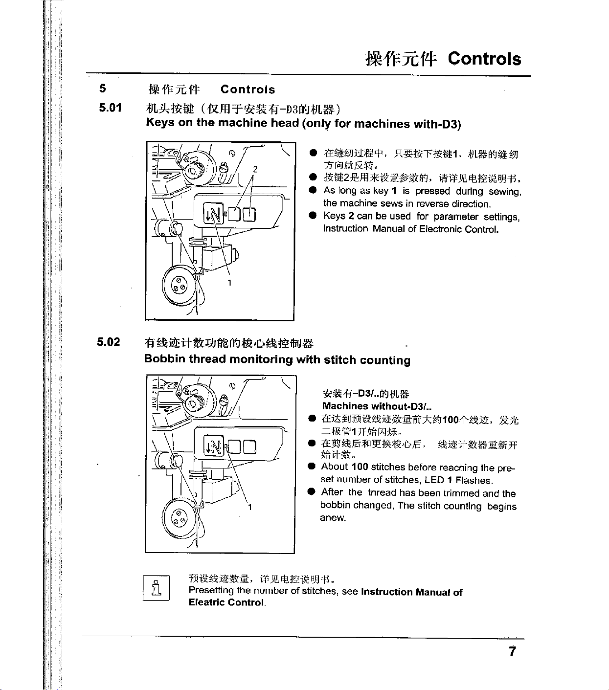
:tt~l'JJu1'1l'P.
7fli'iJ,Sf}tJX~o
•
jg<mam*i&:jf.~g&i¥J,
e As long as key 1
the machine sews in reverse direction.
e Keys 2 can be used for parameter settings,
L
Instruction Manual
JUl~ti.rrjg;'m1.
is
I
1f
~:i!mi.H&
Bobbin thread monitoring with stitch counting
J1Jfil3
1'8
~
•C.•
~
t5!
lliiJ
~
with-03)
m~i¥J;ii
iWWJI\Efi.t£iJIJlJlflo
pressed during sewing,
of
Electronic Control.
i'JJ
:'
,,
i', i
; , I
·•I!
'!'
i
; i
\
'ti:~:fl-03/
Machines
e
:tfiis:jUJ'N
=-
;j,!Z',§l'
e
tE~~J§'lP'l'i:J~;j)H,•J§',
~ilrl
g&o
..
[){Jt!L~
without-03/
i&:
iiJbi'£
1
7f
ftili:Y
..
g&:i:frr:k~'-1
t'l<
0
1
oo-t-~JiE,
~J1Eitg&llli]!l:ili1f7f
:&7't
e About 100 stitches before reaching the pre-
set
number
of
stitches, LED 1 Flashes.
e After the thread has been trimmed and the
bobbin changed, The stitch counting begins
anew.
I
fmi&:~J1Eg&~'
Presetting the number
Eleatric Control.
'i
w
Jl\
Efi.t£iJI.IlJlll
0
of
stitches, see Instruction Manual
of
7
Page 14

"'
'
'['
,,
~1'Fnft!:
5.03
'
'
Controls
ll;!il&
Pedal
/
-:;:--' ~ -
,,
=
0=
ilttll:{iL:li
=
!Jii?JJ
1
2=
tilililiff~tlliH!IJ
Raiser
3=
~~-
Trim sewing
Neutral position
Sewing
C{:[ji:~i'f
roller presser( on
({:E'JO<~i'f-D
..
Il{];l)li!i'iJ:)
threads
-D3
machines
(on
machines
..
1¥JVl<tLU
with-03
with-D
!:;zG,~,:p;,o,-;;!}
2 3 .
..
)
..
)
'
5.04 Lever for lifting roller presser
•
OJ
(!..(Jmjj:~i9.JJJR¥
e
The
roller
presser
turning
lever
1
J"ili!fl!:R$&Jli)jj;jJ
can
be raised
1.
0
by
' '
·
•. · ·.
:
~
' i
1
5.05
8
JJ;fJHf
~~~
Knee
~Y,
lever
I
~~
f--"1/
~
-
J
I
e
PJ
(!..(
JillJ::tloJ
:li<:J"ilii9!:R$&
e
The
roller
pressing the knee lever 1 in the direction
of
the
presser
arrow.
ll1i
~J!Jf7k1:f
lliH!IJ
0
can
loJ
fiHtJm'j;'jl,;ff1,
be raised
by
Page 15

!fd'J:::JC14
Controls
5.06
5.07
~~*11ri5tll~i@
Key
for
setting stitch length
-
)
'\
i
e
I--
~
I=
~~
lliJl!l!
Swing
/
rliJ
out
7H~
z;JJ
roller
presser
~~
=::>
e JmiiitCFtl<m 1 #
IJf.
(
1$
}Jil.~7.08~
e
The
stitch length is set
and turning the balance wheel (see
Chapter 7.08 Setting the stitch length).
PJE~-'l'-!i!i*11!:JI[~J11¥:.
"\!!:JI~~*!Jf''
by
pressing key 1
) 0
e
~
fi
e
When
.
can
downwards.
~
't::
be
!iii
Jli
,
f~
the
swung
HtiJ
1il
Jt
lnJ
roller
/t9
,If, ,
7H1ll
presser
out
PJ
$1
by
[;.(
JHi
o
is
pulling
li
lnJ
raised,
it
lightly
T
~
it
9
Page 16

~~;fiJiA$
Installation and commissioning
6
6.01
-.t:
~
;to
iA
:$
Installation
Rfei'f~~f!\8(]AJJ:ixtiJL4l~Jtt1r'ii:':\i!itn\Jct$!
13:!1'!.
Lh
'.t:
The machine must only be installed and commissioned by qualified
personnel!
All relevant safety regulations must be strictly adhered to!
·
!zp
!iiHiit~Jl
~:fJL#'fP
~~~~fi~B(]J§l~~~~~$~W~~JEo
If the machine is delivered without a table, be sure to use a otand and
table top that can hold the weight
It is very important to ensure that the stand of the machine
steady, also during sewing.
~
Installation
~i'Jl.#'ll:~Ji!Jr.\1:,
~:tn.M'll:&Ji!Jr.\1:,
The site where the machine is installed must be provided with suitable
connections for electric current.
It must be ensured that the standing surface
firm and horizontal. and that sufficient lighting is provided for.
&:,
and
{il!
commissioning
:ilt
'if
PIT
1f
l'l
:X:
R'JJ
tJVf 'lll'ifi'
>t\tJl.
fJj(
#tilt •
B(];ll!jl:
o
&;'§l)j~
~-~~-.-~B(]Ji!JOO,
!
3l:
.!£
~Jll
JE
!
mn
1'P
a1
J'JI
ffl
a<J
tJl.~lll
of
the machine with its motor.
~tJl.#t§:(q:B(]
>t\i1Jii:J3:!
a
Q 0
~&~*B(]R~.
of
the machine site is
f.lj(&;,~91
1!lHIU~i!t
is
firm and
ffi
··'i
.•.
:1
' '
:::;'j
: I 'I
'
:'
'
~
6'
0 1 . 0 1
~~~-lll~-8(]-~.
For packing and transportation reasons the table top is in the lowered
position. The table height
€1'
1:&
m;
13£
Adjusting
LJ)
·--
1¥1
iffill!I1E
the
table
u
,--,--J--J
I
'')-,
height
I
J§lf.lj(f~.
is
adjusted as described below.
e tc7t'i!l'HHn2.
Jl_
!,...-'
•
e
e Loosen screws 1 and 2 and set the
J§lf.lj(
]WB(]i@JJJ[
:ltr~H1$1'1ij±i!!fi'~.
i%-Jil'l\f.lj(.'i'f!TlmB(]NJC.
H2tT~.
table height as required.
e Firmly tighten screw 1.
I
I
L_)
.•.
.,_,
10
'
:''
e Set the required pedal position and
'
tighten screw
••
0
B(]
••
~TPIT~o
:Ji'~41§lf.lj(•m£PJT
:lf.A.i%-t~
2.
Page 17

~~:flli:tt$
Installation and commissioning
'
,·
I,
'
I
:
I
I
'
,
:·:i
:i_
l
;
'
'
'','(
"I
:I
'"
1
lj
:j
'I
,;'!
1
.1
!
6.02
6.02.02
$:~~~
Fitting the reel stand
•
e
e Fit the reel stand as shown in Fig.
e Afterwards insert the stand
'ti:~llill$1d%1l&
Fitting the tilt lock
~
l!n
OOJ'JT71'1<~!%~
i'!.\
JB
:11fi%~1ill
A
~
o
;j;i
EfHL
'I' ;!i
ffl
JlJ1i
1lJ
1¥1
t'lUIJ:
Ji'Ht!!fliJJEo
in
the hole
table top and secure it with the nuts provided.
e
a
ffl~ii2[]I;IiEliJJH'1Jtl~'V:l
::nt3fz;JJi:~t'fJ'llllH'1%~1fi<J;fJL~!
:Y-:
;fU
Jfl;j;il:
fBJ
1JliF'f{t
<
00flft141.!Uii
8<J
:r.;
Pif
!
of
the
l o
l'fi'±f!l.
l'iJ
a Switch
;i
'l_li
:
: 1
~
I
'I
;1:
i
Danger
is the started accidentally!
e Screw on the
in accessories, using screw 2.
a Do not operate the machine without
~
tilt lock 1.Danger
sewing head and table top!
of
the machine!
of
injury if the machine
tilt
lock 1 provided
of
crushing between
11
Page 18

,,
i '
' '
I,
::
'i'l
l
l! ( ,.
!
~~~iJ\$
Installation and commissioning
I··~~~
I
I
I'
:1'1
I
i;
I,,
I<
,:
I I
!•
,f.
'I
i
:_·I
6.02.03
6.02.04
~'IU1L~1P"'ii-
Fitting the machine
4
~~m'¥*-"-1¥1
Mounting the flange motor to the bearing plate
cover
•
:tEt~n2
J:),
4
J£,
• m
2
e Slide the slots
cover 1 behind the heads
attach with screws
2 through the
&g
*l1~
sl!li
<t~
H2rw5ttr:tE
:ltrt?
~1;'{}
Tll1Jff(Jfi!!fll'f
~Fn:ii!iJi:ii!iJLrr~!I!!H2o
~~
n
41l\l
J£;t;:.ti
J!ll
ll!l
?J-t?
of
the lower section
3,
then tighten screws
holes.
e Attach right and left cover sections with
screws 4.
Ff:!.7i!JfJL~IJ'm:fil:
e
J!nOOJ'JT7J',
;fJ[2_.L
e
}y\
ltlziMJUill4_t;f$1;1$111to
•
ffJt~;li6[ll!J
e
"Jt~·:ffti!
H
I¥J
~$
• ¥J-!I!!#srr
FH~fi3¥l'-:t/':W11IT!J.€3i~EI'.4J
JE:iiJ
.±J'll:5o
&g
&:
'<ll':'ft?f~
'll'
IE
1>'!:
A3i~~Wl
'f
El'.i9J
El'.i9J
Wiillli''l l"l
"P,
{!
L3'C
AJH!l~H31IT!
~ 0
of
the
of
screws 2 and
t!L'il!IH. ,
fi!!f
t;
'P o
'
e Attach bearing plate 1 to
motor2
with
screws3
e Remove the wedge from motor shaft 4.
e Attach angle bracket 5 with screws 6.
e Fit toothed belt wheel 7 to the motor shaft 4,
located in the the groove
e Screw threaded stud 8 into the bearing plate
12
of
motor shaft.
as shown in Fig.
so
that the point
1.
of
the screw
is
Page 19

I
I;
I
·.
I 1
11
•.
I .
I
·.
''l
i'
!·!i
i'
.!:
1
·:•:11
.
I
I
!
i
i '
rljl
I I i
j:i.
i,!,
.
1
1
1
..
;I
I,
:i
I!
:1
il
~
.,
~~.flliJt$.
.
6.02.05
~
~
'111¥* , ,_
Mounting
iY-J
the
/
2
Installation and commissioning
~
#rf'JLf!J
flange
fJLff:
J::
motor
to
the
machine
:fR
111'!1
J.E!EU
:ffl#9Hi':.l. c
'l!tt~t±3)
Attach bearing Plate 1
to the machine case with screws 3.
(Onely tighten screws 3 lightly
0
.R
of
:li!o:l£1ii.Htlrti'
motor 2
).
lr
I!·
I'
i
I
I
I
j,
I'
I,
I
'
I'
],,
1::
I'
,
'·
1:
]!:
i''
i
I
I
::
..
'
·t
;j
~
11
irj
::1
:
. I
. I
(I!
'
,.g
:111
• I
!
:1
i:l
; '
'··l
'·i
,I
i
~
I
!)
'j
•I
. '
! '
''I
I'
..
6.
02.06
~~itO~
E!e:W
Mounting
;fo
the
iffil i!llf
Et
{fHIUJ
toothed
belt
and
adjusting
•
:tti3:1'lli.lll'1<~tllmltw1
•
mi9J
lt'liL
•
1'Ei3:
the
tension
El'.i9J m li'1
1't'L
lll'JT
0
~.NJii2,
'l!t~~3
iiH!i:
0
'lit
ilim
e In this position fit toothed belt 1.
e Swing the bearing plate 2
e
In
this position tighten screws
i I
I .
~
~
'',,)
'.1
of
the motor,so that the toothed belt is tensioned.
3.
13
Page 20

~~::fllit\:$
'
'.
'
6.02.07
'ti:~**u.
Mounting the belt guard
Installation and commissioning
ftl.~:f!Lff.Jlli:'lffi!Jit?~
of
the flange motor
e
F!l~H2li13[1!JJEE'l'lil'il1JJP"ll
1o
e Attach belt guard 1 with screws 2 and '3.
~i!!H3JVlfJL.'k
m~M\ilJ,
When the sewing head is tilted back, the safety switch prevents the
machine starting when the main switch is
!OJJ§'i~~4at,
:ff,fJL~,ffi,lf~t'll'Jl!HJiJ·tl'flJI.
14
'
:l
:j
on.
r,
~:i:lf~;J{r-llif
11:
Page 21

, I
i I
...
,1
'i
il
• i:l
il
'
.,
. I
I
: I
~
·
.. · .1··.:1
II
::
. : I
~
I
'.';I
. I
' i '
~
l
6.03
~~flliJ\$
"jj\'f
e
•
•
Commissioning
#11'ttJL1ltifiloi'i:t!1fflW,
WJrn<~i'litJL@,
rn
~
\[]t_J\
F-r
til:
±l!J:ffti§ii£:;1[.!!!.
Installation and commissioning
!f!fJlrJfilo
~rn~irtJE;)(;:JJQirtl
il: o
tJL
1*
=it~
o
1'Ef±foJ:tJ
'~SJ!i~:t!7Gtffli;F
<
iw*
i¥l
>jj.41J
rJL.12
i'i
ft
:±l
Ai¥J't¥i
illU\"1
+'f
JtJ
B 'If
i5G
T,
o
nl
"£MI'~'f*~"
i¥J
Ft\
i1!t
t!c:cf
i!f:FF$ o
>tllli
\!13:
ii!J
)
,
e Check the machine, particularly the electrical wiring for any damage.
e Clean the machine thoroughly and then
and maintenance).
e Have a mechanic check whether the motor
available power supply, and that the motor
the
tion box. If there are any discrepancies.
under
any
circumstances.
oil
it
or
fill oil
of
the machine can be operated with
is
the
machine
in
(see Chapter
correctly connected
must
not
>tliilrtfl.;ll[:i'f
in
be operated
IE
11
Care
the junc-
liffl
'·
. I
1.:;
. '
i
'.'JI
:I
~ : ~
i!
II
!I
''l
6.04
~
~
•
e
e When the machine
tJL~.RftiifWtEWJ~±l!l~I¥J.Jill)'ji;..t!
The machine only be connected to an earthed socket!
tJ1AllilE1rllt,
X>Jw:ft
;!;]
4.41J~]l[i¥JtJL~,
6 bar o
If it does not, the motor connection must be changed by a mechanic.
¥~t-G,;911<iJ1*fFJ\9.\::-?I<DiiJE~
-G,;iJ!~tJL~tl<..tlliml~4;
Jrp
:ll<:tffi~,
urmt
m:itt1TiWJ'li11(
is
running, the balance wheel must turn towards the operator.
o
Jrn.ll1)f'X>J,
t~*
Jlii.Ul"
83~\[]t_J\!J.\~fti.>i!rtfl.'Wctli!o
t-U<BZ*ii!E
s.o1
o
1>
"1\\'zi!l'/~l>~"\ffin"
1li.7J~BZ~ilfr7.J'J±.7J
) ,
e Machines with pneumatic equipment must be connected to the compressed air
of
supply. The pressure gauge should indicate a pressure
8.01
adjust to the correct setting (see Chapter
ssure).
ftm~H8x~~
Tilted
"
work
"
113
base
3±0
1
340-5.2
339.6±0
3
Checking
F
"'
~
6 bar. If necessary,
Adjusting
the
air
pre-
A
'i
II
r.
i''
:1
Ill
[)!
··'
~
..I
,..._
"
"'
~
~
@:·
15
Page 22

,
:.I
'II
il
'
I.
J,
J,
, .
:'
I'
' I
!
·
....
11.1
'I
''I
'I'
';I
[!
';
''
i i
ri
'
ii
lj
.
il
!I
~~~1-A$
6.05
E?t!.Hf;ft!lffMfi:R
Tilted
work
Installation
-t
base
and
commissioning
I•
1:
~
I;
;
•.
' ' f !
, I
lj
'
!I'
"
1
,
I
,
'I
l:!j
1,1
'·:1'
iJ
6.06
~~€rttit
Mounting
~
the
table
top
~
""
--"'
-1
__
¥
i
i
i
J-':<1
l.4
~J
3-fl135
~
..
·-·
~
i
I
I
'
~
·~
'
ej
170
'""'
'
II
16
:j
I
II
Page 23

I
I,
,,
i
':
I
'
,i
I
I
I
ii!
}I
·,·I
I!
7
fJL~(f£~
Preparation
'.IZ,cl!Ji:iJ:'il"
!1\J!JliJ
All instructions and regulations in this lnstrution Manual must be
observed.
Special attention must be paid to all safety regulations!
:<$:i.lliJil""'
%Hi:;\!!;
FIT
'I"
PJT
11·
Ef1~!\!Jt:.fnm7J'"
1J
81
~:'E:~.m'iE
!
rJL~fliT
Preparation
~
I
,I
t•.l
J'Mf1Jl*lif!E.Ji'r
:f:EM
irA'~
1ill); '
All setting-up work must only be carried out by personnel with the
;
I
7.01
,f:EZJ9625
disconnected from its power supply by turning off the on/off switch,
1;).
appropriate training. For
removing the plug from the electric power socket.
;fll
ZJ961
I
fe
Jl. ft.
i'F
El3
'll:uffiJ!IZJ\'fiJII
m
*!ill£
.Ji'r
I
it
at.
16·
~m:illiu~
~
i'JlAlli
Iff
<11
0
all setting-up work the machine must be
O,j:JLlli!J:~fJL'ft
81 A !JlJ'G!iJZ
10JJ
.~.
:JT~!l't1!r
o
JA
<11
iJJ:tili
mLt
tltl'lji
or
Inserting needle on model ZJ9625 and ZJ9610
&
~ffit!l*li<fliJJ!
Switch the machine off! Danger
accidentally!
~*B<rfl*li£7HI!!jlj)z;IJ1JJ'lll'Ef1:f0;1t\Z!
of
injury if the machine is started
.R
~ffl134~mB1:mtt
Only use needles
•
Jil'jlj)~!fj);Jlijjlijl
e
t£H*fr2;)!'~
1
;)l'~;l't
"fli~i**l!!:tiliA:f!L#
xtZJ9625:1Jl'tl'i,
xt'fZJ961
e
tf~*H2;1l'~~~tllii!Jii!~@!~Uffii:i\rji'o
Otflll'i,
o
of
system 134
luJ
7'H1lz;/Jo
*
#;fl!!i
*#;fl!!i
o
'.IZ·~Nl!illul
'.IZ·~j)jl!i]luJ
:ti:iil,
Li:::iilo
e Raise the roller presser 1 and swing it out.
e Loosen screw 2 and insert the needles as far
as possible. The long groove must face to
the right on model ZJ9625 and to left on
ZJ9610.
(-:_
model
111111111~
e Tighten screw 2 and swing roller presser 1
back to position.
I
:.
1
,;
I
; t lo
!
Iii
II
'II
'·'i
: i
'
tJL#Ef]Jlliffll[l(
~"
)
The Choice
thread and material used (see
t!<'f:IJl*!iEfJ't\'1
of
needle depends on the model of the machine and the
~,
i::li.fOJ'Jrg)f§g]Ef]M'if4
Chapter 3.02 Needles and threads).
C *
!Jii.~3.02'P
"~Ho
17
Page 24

,
IJ
:1
;t;JL~ft-il-
'
!l---------------------------------
Preparation
1
!I
!J
!
IJ
:I
i'
i
7.02
:B:ZJ9620;t]L~J:~;t]L#
Inserting
/.::...
~
the
needle
~PfltJL1*El'l.ilill'
Switch the machine off! Danger
accidentally!
on
model
ZJ9620
~tBLtn1*~7rrl!!iti:\MiJJ'ill'A'Jfi1~ft'
of
injury
if
the machine is started
:I
'
il
I
il
,,
il
:J
9.1tJFJ
Only use needles of system 134-35.
134-35-*iiitl't-:rlll
e
Jiliti:\~$&£&1!!11
e
;f',{Jf~H2f\'jjlj.AtfWI>
e
rr'lltt~H2:Jt:m~$&llii!!1J~@l~rJ!liiffl:lli'o
1
:Jf:mJt.:
# o
l'il
YH~M
o
f~E::illtiL#i¥J-jj;;#:ft\llli'i
l'il
;t;:lll,
e Raise the roller presser 1 and swing it out.
e Loosen screws 2 and insert the needles so that the long groove of the left needle
is
!I
facing right, and that of the right needle
e Tighten screws 2 and swing roller presser 1 back into position.
is
facing left.
'i
!!
'l
;I
I
I;!
,,
l
l
''
'!1
'
I:
,•
18
,j
:I
'I
;fJL#
I¥Jil!1fll
~" )
The Choice
ad and material used (see
l{JU:k:rtfL
of
li*I¥J
needle depends on the model
1\'J
'%,
Chapter
~.fO
?Ji~tJJ
3.02 Needles and threads).
;t':lll;fJL#I¥J
-jj;;#:ft\lilii
l¥ltt:f4 C $ !A'.m3.021'
of
the machine and the thre-
l'iJ
E::ill o
"lH~
Page 25

' '
'
ill
:i
..
I!.
'
:,!
~.·
·.:
...
11
~
' I j
•.
i ! .
•.i!l
" ,'1
. '
.i
':I
,,
Ill
,,
,·'1
r
'i
I
i'
'I
i
!:
'i!
!:
!i!
t:
) I
·:
;II
II·,!
I i
'I
II
11
7.03
~.r,,~;
lJili-'P~·L.,~f8MIJil'J~1J
;tJL~<l~
Preparation
Winding the bobbin thread; adjusting the primary thread tension
e i'J-1-2i¥Jt.!N.•1
e
j!Q
00Wi?J'9-03~i'3N<"~l'
•
"3
~
1!1lli
r
'k'lUumt\!~1l!i2_L
tl!, ;lf#ft\!JI[i)ii!1#1J
m~:l!*!i1lli25fllt_[ff3,
!il
Z)l)~tl!*li
loJ
:tE~·C.·
0
J:mJL
1m
o
e Place an empty bobbin 1 into bobbin winder spindle 2.
e Thread the bobbin as shown in Fig. And wind it clockwise around
bobbin
e Switch on the bobbin winder while pressing bobbin winder spindle
2 and lever
:tE~t'JHif11'i",
The bobbin is filled up during sewing.
•
:tE~
•
~~·C.·~iii!it\!J§f,
e The thread tension
e The bobbin winder stops automatically when bobbin 1 is full.
.!In
If the thread is wound unevenly:.
1 a few times
,c,,
1
J::
5!HJI:
!1Vf
3.
~-C.·t~~
i¥J
tl!
l'l<fr'oJ
t~t\!~HJZ)I)f-$rl::,
of
:ISJ
?J
,
0
~ m i!'l::ll:J•~
bobbin 1 can be adjusted
tt
4J£1riJiiJ
'lli:
o
by
knurled screw 4.
ill
i
1:
i.'l'
,,
I·
,.
!:
' I
i;
·i
I!
I
I'
ill'
!:
:I
li
' I
" '
,I
!,,
i
• t::JH.!\
e
;ffifS\Ztlll±i!!~Z)I).\'J't\!{R6o
•
:JT'l!U~U5,
I
El5o
Loosen nut
Turn thread guide 6 accordingly.
Tighten nut
5.
5.
·j!
19
Page 26

;ffl~£~
Preparation
'
'
i(
''
:',.1
'I
I
\!
:1
I
,I
'I
i::
:1
,_,
I
,-It
,I
:l
irrJ
1
11
;,i
lj
I'
'
,,
'I
'
!f
ji
lr·,
I
7.04
lliU±!
/~A.t!t
~
Removing/Inserting the bobbin case
/J;.
L.l:!l.
~I'll
t!lo$
EE\iJ;~
!
iHJ.IltJLllli
Switch the machine off! Danger
accidentally!
tt
5Hill/8lz;JJ
J{)(
til
Removing the bobbin case:
•
tr:Jf:l±:i~Jti:j;R~\jl
•
1i't/E9:!&
of
injury
:!&
:]\\
1'11"'1 1 Jl'l!lC
e Open the post cap.
e Raise latch 1 and remove bobbin case 2.
•
e
e Insert bobbin case 2.
e Close the latch and close the post
X1ZJ9620i'!l1l'!li"JW1fi:'Jm
ZJ9620 is shown in Fig.
~
1'7f71'
511lA:!&
Inserting bobbin case:
~Af&%2o
~I'll:!&
e
•
•
•
e Insert the bobbin into the bobbin case 1.
J'L'
I'J
o
:#1-:l&•l):li<A:!&%1
iifrx'!l"rt5'll~2TiiiiJ*t!'l'l'
:f4f
tx
"J'
imii~Z9l~'iJ3iJ!J'll:l&>C.,~i)k.1J
e Pass the thread through the slot under
spring 2.
e Pass the thread through the notch.
e Adjust the thread tension by turning
screw
fJJ
*'
fi<J
fii;
llfr
!
if
the machine is started
'
0
tll:!&%2 0
j'=J
::If
llHn
il\Lt.f:l'J'\:Jl\'Oj;R
'Po
rt
L"J
o
l1L
3.
~ o
o
0
:::1
i-!
,,
'
I!
,;
I
~
i
Iii
I
"
'
I
·I
I
I
:!
.,
'
'
:i
20
~~~M.
When the thread is pulled, the bobbin must rotate in the direction
arrow.
~~~---~~~-~0
il
II
of
,.
the
Page 27

rJL~at-11i
Preparation
7.06 ZJ9625,&ZJ961
Threading the needle thread and regulating its tension on
model ZJ9625 and ZJ961
:k
PJ:i
til ili\ It\
f!f:Mitn.
Switch the machine off!
Danger
e
rt:J.L;f~z;!JJI'§IR"!l.J
•
izp
e 1'EZJ9625W1U:..
#~M/Atcr~J:tl'!¥
e
Jl!ii:t~i9J~1tt!l\fi2iiW'iHH2lHi<J~lt:iJ
e Tilt up the eye guard 1.
e Thread the needle thread as shown
e On model
left, and on model
e Adjust the needle thread tension by turning milled screw 2.
O:!'JLlli'J::l"iftt~:.ff:
im!
iHt~91UJ
0.
iUlt
!
l!li
:&
5'Ht!l~r)J1JJ
of
injury
l'!l
Jifr
71'
v
1t
ZJ9625
§
il'~
m;
I!&
!
if
the machine is started accidentally!
o
~
0
'ft~Jl!,hl,:brt:Jli:V,
0
the needle is threaded from the right to the
ZJ961 0 from left to the right.
ililtEZJ9610tfl.gli_t,
o
in
Fig.
21
Page 28

.''
I
~~·-
'•
;I·
I
il
:t:i
i,
:r.l
1:11
i:
·,·II
'I
1
ll1
'1'.1.11
tJL~<l~
7.07
,':!I
I•
,.
·'
'·[·
i
'I
I '
' '
I
''·
'1.
I "
II
I·
i·r
ii
,[
!:
iII
I; I
''.
',l,.r
..
I!
If,
il
i
I f
'
''
...
1'
I
'
..
!.·II·
' ''
I
:
1:1
11
11
•
!
:1
i
II
i
1·1
l
rll
1
1
1
I '
"'I
[,
,,
I,
il
Preparation
;fEZJ9620:t1L'M
Threading the needle thread and regulating its tension on
model ZJ9620
*IT:!
=mi!itJL~
Switch the
Danger
•
•
e i±.:!i::illwi'Mt
•
e Tilt up
e
e
e
l:tf'tt~Ji'iJiii1Ht·;~'*:1J
tJL~
Ei'l
~
!
.lli;:Jt-:l!!liEfl4JJ1tiit
machine
of
injury if
II•J
1.:
11!l
i;ir!NI'! 'ill
~p
f'ili'JT='K'!i"l\'l1-101
,12/Ah:
:ii!irl~$Jl~rlt~~2i)I;J'ilti"t{li{]1!(:)J
Thread
The
Adjust
left
needle
[OJ
the
both
needle
from the left
the
l':l'!i"
eye
needle
needle
the
_t,
0
guard
IY~fe;llft
off!
machine
'
is started accidentally!
1o
~
0
~I
~_!;1,/A$
1.
threads
is threaded from right
to
right.
thread tension by turning milled
[OJ;:tc!.f';
0
as
shown in Fig,
to
jljj;fr:oiJ:illwtJUt
the
_L
it~
left, and the right
screw
2.
I'
:111
'I
i\
'!''.
i·l'
li
I':
I
I.
i I
I·'
'.·.
'1·1.
,,.
I,,
:
:·,:
" '
[!
1!
i
r
:r
11
::.I.
;I
!
il
·.
ljl
:I'
I
1
I
li
li
'.'''
I
,
.,
'j
,
'I
I·
1i·i.
I'
I
' , i
~
[;
:f
i'
I:
I
~
i;
'if!i
;,j
!':J
'
~' ! ~
I
22
Page 29

;f:JL~fl~
Preparation
7.08
!9::E':~~*~
Setting the stitch length
e W Hl!D Jf'
e iliH'JiliT ill! 1
Jll:K/tg& '¥
roJ
lft#'il!J
:Jt:lk
EJ
&:
e Press key 1 and at the same time turn the balance wheel until the
stitch setter clicks into position.
e Hold down key 1 and turn the balance wheel to and fro until the
stitch length required is shown on the scale
of
edge 3
the belt guard recess.
s
¥~
@I
±i!!#Z>iJ
'IIJJP
"'I
][$U
~Jll:i/lf\'i
¥~.
['lJ
;fill
WJ
T
imr&J
1i¥U:tciiU
ift~3k!:xt
ifilXAJE
It
l1!2J:JiJ!
ffL
ffLjt
i\W~
i&i'il
o
1r o
2 opposite the bottom
ll'1
~
'
':1
''I
"·I
''II
:-·'
23
Page 30

II:
i'
Care and Maintenance
8
Care and Maintenance
~f.!j
................................................
rm
i!:tft
~
c tUI! m
i'i'i
JiiE
i11
!Ju
i!l3
11£
ll>t$~
jiiiJ
i!IifFI
>1ft
J'l'iiJiil
il
'i'"lJE
~
f.!i
'i'
-9,
iJil~
Clean
..
····························
Oil level {thread lubrication/hook lubrication)
Oil the hook
Lubricate the
Check/adjust air pressure
Clean air filter
l::i£ ~
Jtl'fJ.Errll1riiJ:lili:l.lu
These maintenance intervals are caculated for the average running time
of
a single shift operation.
shorter
tJifE
i11
m
no
· · · · · · · · · · · · · · · · · · · · · · · · · · · · · · · · · · · · · · · '&
· · · · · · · · · · · · · · · · · · · · · · · · · · · · · · · · · · · · · · · · · · · · · · · · · · · · · · · · · · · · · · · '&
· · · · · · · · · · · · · · · · · · · · · · · · · · · · · · · · · · · · · · · · · · · · · · · · · · · · · · · · · · · · · · · · · · · · ·
.1J
· · · · · · · · · · · · · · · · · · · · · · · · · · · · · · · · · · · · · · · · · · · · · · · · · · · · · ·
@
iWJ
m-@
~
J1
iJill"'
· · · · · · · · · · · · · · · · · · · · · · · · · · · · · · · · · · · · · · · · · · · · ·
···daily, more frequently
...................................................................
bevel gears
of
air filter/lubricator .. ·
1!¥:#
i"BJ
intervals are recommended.
......................................................
................................................
~
Ro
~
:Jm'&:R_Jj).:f)I
l¥rt11fi'Jl.
T.
Y!i.JC~m
If
the machine is operated more than this,
!ifJ:R_,
........ · ........ · ........ · .. · ..
fto~
I¥J
f!f:~rBJ
JzU511ol\f~J.E1TIJt,
if
in
continuo~o,;
....................
-'!":~$]
tn.~J.E
'~
o
· daily, before use
1Til1
:x.
72. , 7ftfl,
ii-72.,
daily, before use
daily, before use
· when required
i"BJ
i!i1:
!ifJ:R.$;-J;:
,
7HJ1,
:t.litr
:t.lltr
'&:¥-IX
3f
tn.:t.
iltr
:tE
fill~
lt-J
operation
once a year
:IE~
0
:tEtn.
•
·'
8.01
~
1f
I
iJilJTi
~
Et..ffi
1J
Checking Adjusting the air pressure
e
:tE
4l)'
IJ:3f:fJL
~
'i'""'
ffi
e
"t.lli~11:16·~iJiJik:ii'6
e
!lP!ll!fm~ll1,
•
,l;]Jll:;,
71'6
bar~
e Before operating the machine, always
check the
e Gauge 1 must show a pressure
e
If
necessary adjust to this reading.
e
To
do so, pull knob 2 upwards and turn it
so that the gauge shows a pressure
bar.
1:
i' l
24
I',
~:I
1'·1
1lrJ,
ili~'l:!
7t
>1ft
J'l'-9,
Jli~1l:~:ii'
jJ
0
bar~'Y'"'l,ffijJ
0Jii'J~Jit11L
it.Jl:tHfJifE~Ji(Ecffi2,
'i'
-9,
!lifJ
71
.¥ o
air
presure on gauge 1.
HLI:"'l,ffi~Jlk
of
o
6 bar.
of
6
Page 31

Care and Maintenance
8.02
mm~
"''.ilttfr!I~
/ifEint~at~:i:!iltt
Clean the air filter
=*
m
1'JHl~
ltl.imi
hA.~
"'\il!iii!l'~iiliJ
Switch the machine off!
Disconnect the
~
of
the air-filter/lubricator
'
ffi'~
J:
tJl;
T
Bim;
~"'\
air
hose at the air-filter/lubricator.
~
7.klf
1 'P
Draining water bowl
e
:tEhA.~
tt~
!§',
"'\
e Water bowl 1 drains itself automatically
when the compressed-air hose is
disconnected from
ii!fiS
tt~
Cleaning filter
e JTT7.ktf1 o
•
Jf)C
:±!
J1
il!i
•
ffl
E!i;m~
e
JT
Attil!i
~/~'Jtlf~J:o
"'\J"il(;='lf
e Unscrew water
e Take out filter 2.
e Clean filter 2 with compressed air
isopropyl alcohol.
e Screw in filter 2 and screw on water
bowl1.
tt
~
o
(!<]
1.k
tiF~,
1:
~ii!l'~iiliJtlf
7.ktf1
1"'12'
1"'12
0
1"'12#~
i!Hi'i'
<P
(J<JJJ'i1l
the air-filter/lubricator.
2:
!F
p;j
~~
1.ktf
bowl1.
T
i9Jtlr~
1'I'J
1
~§I
$U ~ "'\ il!iif!l
E!im;~
"'\
0
or
8.03
fr!Im
Cleaning
-cy7i:if!l~i'flifE'*,
Clean the hook; hook compartment and toothed wheel 3 every day,
several times
* m
1'M~
i'Jtjj(tJL
Switch the machine off!
Danger
i1U"::~Ht!l!l]i9J
of
lifE'*~fol6i·$&3,
if
in
continuous use
ltl.imi
'
195
ilf
(!<]
ie;
~
!
injury if the machine is started accidentally!
J£o:l!tl'f~JE1fl!>t,
-cy7i:ii!J~a$ixo
25
Page 32

Care and Maintenance
•
~#;JfJtl\IJ:!l\!'i1'1j{j'[J!l'o
•
rr
7f
tt
'rtmo:I!Hill.
•
JT;f'~pgftl:!J<j§-1
e
#z;!J'f-1'&,
j1'l
1*1
/\:t<J5mm
• If)(
:±l1*
J'E2
•
ffl;piJ!lljj!fjj!j)iJE1*j>!'l
• ~ Jjj(/'..1*:J';:21lt'
?tlll!i
il-A
•
JT~I*J:jgt:!J<i511¥Jt~~:Jt~ffitt'ftmo;j)j(rjl1l
e Bring I he needle bar to its highest position.
e Open the post cap and removP
case
cap and the bobbin.
e Unscrew hook gib 1.
e Turn the hand wheel until the point
2 penetrates into the groove
case
hook race approx.
e Remove bobbin case 2.
e Clean th hook race with paraffin.
e When inserting the bobbin case 2, ensure
that the horn
in the groove
e Screw hook gib 1 back on and close the
post cap.
fi<Jt~~
J[3'1J1*%2E8~;lifflnrA!ifE1*E8~
o
0
#:tJi(
E811fl
of
the bobbin case 2 engages
of
the needle plate.
I!Jul:J
i31
:Jt'fll1*
0
0
~lil!i
t'ri31J'E2
j1'l
'f! o
5mm.
.c,.
0
E8
"" :±l4;liffl$
'he
bobbin
of
of
the
0
'
bobbin
II
'i
8.04
26
~nfE~:tmllll
~:A.
L.J::!l.
Oiling the hook
~
fjj
:l!l
~
Efl.
iJ]i !
:fl111im~ii:>'r:l-t!!JI!\Z9Jijj~8'"m;!lfr'
Switch the machine off!
of
Danger
injury
if
the machine is started accidentally!
e
4l$7'.:8:1-2
e
1t;fJL~UJ::$lltr.&tE*l!llf-'J<;fJLJi§',
illi3'1J!iiE1*1¥Jj>!'l
e
Pour
hook gib
i!llii!lll'IJ
'fl (
1-2 drops
daily.
I*Ji31:!1<"i§"E8:JL
~
of
oil into hole 1
e Before commissioning the machine, and
long periods out
after
few
drops
of
oil into the hook race
(see arrow).
1
il:AJLi!lli
Jll,
llif:!I<!Yf:>F)
of
operation, pour a
'f!
of
o
0
the
Page 33

Care and Maintenance
8.05
8.06
me~
lf'fl
m illl
Oil bowl
for
_,
~
~~rl'ij
i'IUWfl'f.J
Filling
the
:;\[
hook
nil
oil
reservoir
lubrication
I--
'~
'
n"
""'
::3
_,
:;1[:1Jo
ill!
of
the
A_,
~
(£:".,;;/"
~
thread
i'E
1Jf
i:X.If
1:Jl
lltr~
1'l:
ill!
:li!:o
:J6,;_m~
ftirfl
i[1
<P
tr
iJ]J
0
Check the oil level before each use.
There must
1.
Jm
511:/lii
If
required refill oil through hole.
.Rfti/ff<J:'FH:tE40't
22.0 mm2/s
0.865 g/cm3
Use only oil with a mean viscosity
22.0mm2/s at
0.865g/cm3 at
always
'll!
PJ
il!U:i!.JP
;f!li'~15'tlltffi'ffl'j,J
be
oil
illHL:!m
111-'JLJ:!JJ!iliffl'
Ef.Jifil?i'rilll
40't
15't.
o
and a density
1llJ
in
reservoir
o
j,J
i*~
of
lubrication unit
of
i'£4Jti:J;:7f;fJL
16,}!iliJIU<l'illl
Control the oil level before each use.
There must
l1tr1\H'f.illl
t:\:1
always be oil
~rL
't'
~i;t-11
iJlJ
o
in
the reservoir 1.
e
izp
5I!:
e
If
necessary, fill oil up to mark through
hole.
JQii'HfHf'~FH
We recommend thread lubricating oil .
ilif'lfoJ"Jii11.JPilll'J'L!.JP
~ifilfitil!l
illi
i~t>FiiH£
o
o
27
Page 34

Care
and Maintenance
8.07
~~1fl'I!J~liiiJ7fql'l'f
Lubricating the bevel gears
~
l'dl
,jj L
ll!i
Ell
im
!
~
tit
;fJL
~
l'i't
71-
it!!
iEf,
ii!J
{J]
*
1¥1
fit
llfr
Switch
Danger
•
e
e All bevel
e Tilt
Jm
Fig.
e
e
e
e
16·
tri'E;fJL:c'k:iMtrluz
Use
Danger
the
machine
of
injury
J'Jr
1J
~
llieti':
mrJ
(n]J§'JIJJ~t!lc'k:t~3'UJ!dtf
gears
the
sewing head
OOJiil.:if-:1
~111!
\ZJ 962D.tll1\'!i¥Jojl:
shows
the bevel
Mi:l.t~
il;ieti':
i'E:JiHJL:c'k:1JJc@l
'l!l;1[
ftr~
0
Apply
grease
To
set
the
sewing head upright, press tilt lock 1
sewing
jjij
head
ffl
)\)(
'f-
of1l.
til.
both hands
of
crushing
off!
if
the
machine
1l):if:•J6·
%i!Jn
~JJZ!lsli
J:,
must
be
supplied with
back
gears
1¥1:1:$
J!i'1l:
to
upright using both hands.
.4-
to
ttfjlj!UJlD
iiL
'i'!i'll1.
all the tooth flanks
liJ(_
IPJ
@;
fi
1"!7:
fsH&:tfftn
set
between
ll'Jfitllfr
the
sewing head upright!
!
is
started
i!ll
~~,
onto the support.
lli~tlii~,
of
the
ZOJE 9620.
<
!\1,
il1i:c'k:Ji!r7J')
7t
(n]
Fnt:iilllJtl<f!l(llfr
lll'
1
the sewing head and the table top!
accidentally!
new
grease
once
,
1. # m
and
the rack (see arrows).
backwards
a year.
xX:'f-:Jt-1'Jl:c'k:ilJI:f0
and
set
the
'
~~
~
'::
i i 28
I '
I'
i !
'!Jtfi'Jf!E#-f'effl
We
recommend
*'I
F.!
:Ai:'1
sodium
7\J
1SO"C~l'i*J
grease
with a dripping point
i1lJ
Hi'l,
of
approx.150C.
Page 35

ill.
II:
It
II
ill
I ~ ..
II
! I
I
I '
I
I.
Adjustment
9
Adjustment
ilt
~~'#
'1\'f'i!H!G
~
~ii!E...tffl!i:lf!
'Htl!ttJLMi~&Hi!!.ili:\Zif.J{jjfiif
Unless
be disconnected from
Danger
ljlj,
i"i
ijjrJ:tEJ!IT'il
if.lJ
~I
11'
cf'
~·~9!
¥-HJL~
fi'Jfe:l>fr!
slcled
otherwise, during all adjustment work the machine must
electric-and pneumatic power supply!
of
injury if the machine is started accidentally!
,1,\
rtiliR'fO
IEJ11i
~k'\
f:,Jt
9. o 1
9.02
xtoo
~
r
f'F
tr.J
tJelf'
Notes
e
e
e
e
on
adjustment
l<#
cfl
i!ITJ:t
a<J
J'JT~
"if.lJ
Ji<:I
tMZJ:fHJIIB'J~\[]<A.ffl
;ll~
llJ;;:J±:fil'i"f
J§~:ijt"Pa<JJr[!l!!fJY:MtJL~i\'illir:i:l'fl.lii'J'ilHEIJZ~lU
J:i!l'iG)jj(;*1l~ijl..riJ!A'U
~t£:J%.!i3"
Ziltr~:Jf,
..fU
"if.lJ
'II!<
I
0
I*JI¥Jt~lfJ,
#1:r:"if.ll~I11'2J5N~l'#irr~o
fi'W
*:fc)jj(;o
1'~
rp
mf:'l.Hfl;
f'F!:V!JliL
t~JJJ::!ll:ffl-*'IBI:>Et!Lil~li''l~ll1l1'F.
1
~
Wil-:l
:3':'1.4l3C'lt1G
T
jj
:lli:l'#iil!t...t
IJ!U,'l:!B.:~Riltr,
Lf
8'J
t!Lil~
fi<J
tiL~
ffi
tJii
fi'Jii!Jiff.tfr3itl
JB.li'i:"P
o
o
JLE:LR
i'£)1:-r;t
'f::{I'J~·@11:r:"if.ll:lli':Ift
cp
o
:tzu*DH!:'H
fc
it
¥.f--F
El3
'll::ct
:pj:J!ilR
§
li'J
o
e All following adjustment are based on a fully assembled machine and may
only be carried out by expert staff trained for this purpose.
e Machine covers, which have to be removed and replaced to carry out checks
and adjustments, are not mentioned in the text.
e The order
sequence for machines which have to be
individual work steps are carried out, both the preceding and following
chapters must be observed.
of
the following chapters corresponds to the most logical work
completely adjusted.
If
only specific
e Screws, nuts indicated in brackets ( ) are fastenings for machine parts, which
must be
T!\l-,
Tools,
e 1
1!''kllll'!\l:l:lr2
e 1
~JFJ:l.R-j-7
e 1 '!l'1.5 'E 6
e 1
1'-3/Ht
• 1
te~!lii.R
• 1
1"-:;!:'lm
e
~f'Jl!il<'fOm~tt'l'4o
e 1 set
e 1 set
e 1 set
loosened before adjustment and tightened again afterwards.
liBJ11."¥1l:Jt'l?:!flllfiJrl't:¥4
gauges
IJl;
and
other
¥:1
0 mm
.3':
mm
o
1¥J
B'Jijl
13 mmi¥J71Tij)j('fo
I*J;'\:i!it~Hj)j(
accessories
""
7J
'¥-o
r 0
0
of
screwdrivers with blade widths from 2 to 10 mm
of
open ended wrenches with opening sizes from 7 to 13 mm
of
allen keys from 1.5 to 6mm
e 1 clamp
e 1 metal ruler
e 1 gauge
e Sewing thread and
lest
material
.,
I
!.
'•
:!
I
, I
,,
1,,
' '
li.
:
'.';I
:i
29
Page 36

iffijfl
Adjustment
9.03
iffil
m~
liiilm&
Adjusting the basic machine
9.03.01 ;£EZJ9625
Needle position
nll!J!U
~¥f~l2E1f:l'ttll::'i!3itlllt
i¥:1
<P
.c,,
Requirement
With the stitch
in the centre
';fn
ZJ9610mm!J::lM.iUJJ1fiPJ_r.~mtt-IY-Jffr~
in
sewing direction
1
1'1§:,
JArla~iiiJ:;5"rlal!-.
0
length set at its minimum, the needle should be positioned
of
the needle hole, as seen in the direction
•
iJ!:}UU:/iuJ'i¥J~J2f1f:[!!'o
•
f!imi~!\!!Jlui);Jmttff
e
Set the minimum stitch length.
e Adjust needle
c
~nD
bar
(screw 1) according to the Requirement.
on
the ZJ9625 and ZJ9610
Vl#ISY:~i!l:'Fttt!Y...ttt:rL
of
sewing .
"
'
30
Page 37

I
;I
Adjustment
I I
;I
li
i!
i
••
I
•I
9.03.02
;fEZJ96201:1LMJ::Y.~m:n
Needle
position
in
(ri]
sewing
#tiLtf-f(.Jti::li
direction
on
!;lj!JJ!Ij
MJiiWJJJ
Requirement
The needle should be positioned
in
loJ
'~if.
;fJL#
the direction
e
ti<AAi'JllJJ!IJiJI,HI!!'#ff
of
!§Z
~1fl:'f-#;j)j(J:
sewing.
C~<ITHU2)
tflUt<J
in
the centre
o
e Adjust needle bar (screws 1 and 2) according to the
the
ZJ9620
'P
•C.'
o
of
the needle hole as seen
Requirement.
31
Page 38

'
111
J
i i
I·'
l·!
r:
""
,[
i
i
!.!
I ! !
I
i:
i
!'I
I
-•!
" "
I
',
11.
!il
I'
~~:
:
[I
I I
1
:
~
i
1
I i
I
11
" I
i t I
i ·f;
1
i
·
1
i
-!
i
[:
;
[I
l
ii
I
!'!
, , I
I
~
~
I
i,:
I
'I'
" '
11
:.'
•
,II
1
'"
' h
I
:
!:!
I
I!
I
!.1
'
!I
I
I i
'
'I
, I
I
,,
I ji
9.03.03
Adjustment
m
tv
ifni
If
l't
Jr.J
l@i
m:
Preliminary adjustment
li!l'.JI!IJ
~'li
;ff{j'['f
Requirement
When the needle bar is
approx.
_t:fEr.':Ort,
21
mm between the needle point and the needle plate.
•
JY:J\\UlllJi!tliJlillll'l:~;ff1
:tHtOid~tl~~zjfiJ
at
e Adjust needle
Requirement.
of
the needle height
1Hm1'i:A~'J2I
top dead centre, there must be a clearance
(~n2) , /G'll!1'tz;IJ~Ho
bar
1 (screw 2). without turning it according to the
0
mmftil~l'!i'A'i
o
of
I.,
i:l
i i i
I
I
1:.
I
I
I'
2
li
i i
1
1
!:i
i ~ ' i
1
11
li
! i
li
!:1
1:
i 1
ill
I
I.
I
i.!
i \ i
1
r,
l
1
li
; '
II
:,:\
1:
-'
!I
32
Page 39

Adjustment
I'
,,
i I
I '
I
!
n ,
I!
i
i'·
9.03.04
:tEZJ9625;j:JL:MJ::'iH
Needle rise,
i'!tll:7L
hook
tifE~i'Utti'!tJl!l!l!\,
ttl'l''.li'ili!Jt:fu~tt~
clearance, needle height and needle guard
on the ZJ9625
nll!JIU
~iY:E:~n!'~tlO\J
1.
JilitJt:J;;&:·~Nfl'i.f#l¥irr,c,,,
2.
mHLI¥J..t:ltii!lt&:·;.m:tt!ifit&g;;
3.
J?<ti·~6&:·;.!Jj!j£1£±t!rl'l;.ff-IJL#,
Requirement
With the needle bar positioned 2.0 mm after bottom dead centre and the
stitch
length set
1.
the hook point must be
of
0.05
to
2.
the top
3.
The needle guard 6
of
"0.8" ,
i4J#l'FJ'ii'
Jili~3'1H·IIY'l~Ji:l'\\~0.05
'f·:tETYEJ!:\Z.J§
rjjijo.a
at
"0.8"
0.1
mm
the needle eye must be 0.8
..
:
at
needle centre with a hook-to-needle clearance
must
touch the needle lightly.
..t:JT2.0
3?:
3":1.0
mm,
to
1.0 mm below the hook point.
0.1
mm
mm,
&±:
I.
I
'
I·
33
Page 40

I'
I'
,,
I'
II
,,
.
I,
'.'I
'
"'
l ;
'
'.1
' '
' ~ :r
; i
!
i:
' I
I
;.;
'
i,i
I
!!
Adjustment
e
W:lll'i11G~*Nt1
/ •
JTtct!!m.
e
'*#;ff:~
e
'*
li!Eott~~f.'Ei~JH:Il/ft<F
e
W:J!iii*2~Ji.!ll!J!tli/lll'llHliY~
•
:!riftl\~1
e
lif!!ffi~&#:i!iitl:Z.fBJ'f'f-]EfBJ!l1i!#@~
e
f!Hl'!{f[ll!7;ii;{±~ti:f1f;8,
e
JriJKUil3~l<J\lJI!tliJlil1111JP#~6
e Set stitch length at
e Loosen screws
e Bring needle bar to
e Set hook point at needle centre, making sure that the needle is not
deflected by
e Adjust needle height according to Requirement 2.
e Adjust hook post according to Requirement 1 and tighten screws 4
5.
and
e Making sure that there is some play in the bever gear, tighten screws1,
e With retaining collar 7 touching bevel gear 8 tighten screws 2 and 3.
e Adjust needle guard 6 (screw 9) according to Requirement 3.
"0.8".
2.
3,
4;fi:l5o
crF
7E
A
Ji'i
...t7'1-2.0
~JJ\l!iltl~lll1':1iJEott
"0.8"
1,
2, 3, 4 and 5.
2.0
needle guard
mm
91:,
,c,,.
lif!!f~JP#*~6¥51:1'lm!llGtfL#ili!*lo
,:;:,£
o
Eltt#JT~!IJSl<fJ
JT~~H2'fP3o
C~H9)
.
mm past bottom dead centre.
6.
4'.f'D5o
§ftD,
JT~t!!H1
o
'
i ! I
l
i :
'1
I :
,j
' '
I'
i'
'
I '
'!§ £
=PJ<:IiJE
ott
111 ' lif!!
When the hook is changed, make sure that the markings 10 and 11are
both on one side:
fj1[
Wl1'
ti1<1C
1 0
;fi:l11
:a
fi'J
-:ill
0
34
Page 41

Adjustment
I
I
'
!;II
9.03.05
~ZJ9620tJL'!Wl:ttfttll:fl-,
Needle rise, hook clearance, needle height and needle guard on
the
ZJ9620
li!ll!il'J
1'£jl.lj
-1'
litfi8LL
1 .
liJE;/8t:'R'.IZ•
2.
#ilHL~J::iil!;lt'.IZ•{Yli'£;UJt;/8t:'Rril!i0.8
1?~1
3.
Requirement
With the
hooks,
1.
2.
3. The
~916•J9l!i'1:1'llfi!l;i'i<J!l';tiLit
needle bar positioned 2.0 mm after bottom dead centre on both
the hook point must be at
of
0.05
the top
needle guard 9 must touch the needle lightly.
*-l-HH~T-i'Er~r.'I:Z.J§
@l
i!I:T#
to
0.1 mm.
of
the needle eye must be 0.8
lilHUIJ'ttfttl~el!\,
li~
9"
•I),
;UJE;/8t'EU#~JIE~~o.o5
35.1.0
o
need_le
centre with a hook-to-needle clearance
to
ftfttl)'i:jJtlf:I1Nt~
J:.7T2.0
mm
Jd::
35.
0.1 mmo
mmo
1.0 mm below the hook points.
'
'
: I
I
I I
I,
I
I ,
I,
I
•
I
l
I
;
'j
1·
j
'
,]
I !
I
I I
35
Page 42

!
I
.I
I
I
:
!:
•
I;
I I
i ! '
I
;!
I
l
l
I
1:
. I
.
I.
: !
I I
. I
i !
I
:.
I I
1·
I
I
I
I:
(
I
I
I.
I
I i
I I
"
I I
I
!l.
I'
i I
I l'
I
I
'
I'
I I
, I
l
!
I··
I
j,
I
l1
Adjustment
•
trf'~t~ff1,
•
t}.jllHI!!tff'~t~ff8o
e
iiftttrllt-T
•
iif
f!!i
-t-
e
:!!!
.J!li
m2
e
ti<Mm1
e
tf'l;U~ffHU6,
e
li1!11Jlf.£1Jcti;J*B"/ll'JZfilJ1'i'lll'l-JtfaHJJ!:#JE!ft
e
fiH~{f[IIJ10:!i'l:fifJZ.-®~11,
e
!iH~{f[li'll12~fifJZ."t\J~13,
e
tEJiJE~ttfJ{Jf!!iiZrtr~!Ji!lH7,
e
t!i'ft'R~3;;H\ll!iitl,
e Loosen screws
e Loosen screws 8 slightly.
e Bring needle bar to 2.0 mm past bottom dead centre.
e
Set
both hook points
are
not
e Adjust needle height according to Requirement 2.
e Adjust both
screws
e Tighten screws 1 and
e Making sure that there is some play in the bevel gear, tighten screws
3 and
e With retaining collar
e With retainting collar 12 touching bevel
e Tighten screws 7 on both sides
e Adjust needle guard 9 (screw
Requirement
~'!!!¥Hfi'~O;J
When a
both on
hook
one
2. 3,
T?iEr.':i!§i
!iiE~~m
%:!1!l!iitl
%:!1!!JiitliJ;J~fl!l-t-liiE~
deflected
hook
8.
5.
,
lilfl{~j!Jj"-1'-tiFic
is changed, make sure that the markings
side.
4,
5,
6i'Q7
0
J::Jt2.0 mm
i)liJ~3itl
i)liJ
1,
3.
mil·
>liHMl
i'tf!!i-1'-liiE~~t
posts according to Requirement 1 and tighten
D'>J
,:J,
tr~t~tJ4,
2,
3,
4, 5, 6 and
at
needle centre, making sure that the needles
by
needle guard 9.
6.
10
touching bevel
Jtb
'1'
'L'
•
lil!lf~J?
tt4lll9'ill1l&
!'to
E;
tt#l'T~~HB
tr~!Ji!lH2o
i}I;J#JJ"tt~9
7.
gear
of
the post.
14)
on both
13
gear
hooks
J!Q,
o
1':f:J;"U;H3~5o
C!Ji!lH14)
11
tighten screws 2.
13
tighten screw 4.
1l
ii!tJJJZ11t
according to
15;fQ16t£Fiil-i2Lo
15
and
tt-{.lil#4
16
are
o
36
Page 43

Adjustment
I!
i
I.
:
I!
II'.
I •
I '
I
I,
I
L
I
I'
! :
'
I!'
I j I
9.03.06
a~oo1oma~~~~*·
••~~~~•.
#~--~~~•
Needle rise, hook clearance, needle height and needle guard
on the ZJ961
ml.D!U
~i!iUi[~Jll:1s(tt1-J
1.
Jili~~>JZ·~llffflHts<Jcp.t),
2.
mULs<J..t:itl~>JZ·~N:tfliii~~Tiii0.8
3.
t".fi.M61Z·~llf~~±t!ri'MiftJl
Requirement
With the needle
stitch length set at
1.
the hook point must be at needle centre with a hook-to-needle clearance
of
0.05
2.
the
top
3.
The needle guard 6 must touch the needle lightly.
0
"0.8"
bar
to
0.1mm.
of
the needle eye must be 0.8
,
;J4Htffil'rtET7E.9:Z.JJ'i ..tft-2.0 mm
Jili~'Elitts<J~E[~~o.os
i't
o
positioned 2.0mm after bottom dead centre and the
"0.8"
:
£1.0
to
1.0
It
0.1
mm
mmo
mm
below the hook point.
Jtl::
o
I
I
i
i
!
l;
I
.
i
I
: i
!.1
. i
, I
I
'
37
Page 44

Adjustment
•
i&tllt!3!:l1E*!'l!'7:1
~ e JT;f',;~n1.
/"'
e ¥J"-H:ff'if'fTl'Ek\J§J·Jl2.0
e
¥f
!liE'*~
e
t!iJ11Ufl2~~.ffi!i!Ui);J'!ll:;f!l#ii<Ji'11i!'l!'o
•
tiill\Ufl1
e
liiHmii>tM~ili'J:<::.fOJil-
e
Jtl
e
ti<Jl\Ufl3~~.lil!i!Ui);Jll'f.:tf'#~6
i);J ~ l'Uf!Ht
~~.lil!i!Ui);Jl!I@:JiiE~E!t±;f!'JT~~H
~R
ffi:
III7!1Hl:
e Set stitch length at
e Loosen screw 1, 2, 3, 4 and 5.
e Bring needle
e
Set
hook
point
deflected by
,,
,,
I
e Adjust needle height according to
e Adjust hook post according to
e Making sure that there is some play in the bevel gear, tighten screws 2.
e With retaining collar 7 touching bevel
e Adjust needle guard 6 (screw 9) according to
"0.8".
2,
3.
4i'U5o
mm
kb
if'
•C.'
•
liftim:t?
H<Wi6N
1l
:G!t!ilGtfl
HiliU#il
4o
J.EfOJilllt;f!'JE~
ii>I:IH~B,
bar
to
at
needle centre, making sure that the needle is not
needle guard
"0.8"
2.0
tT
~'I.IHJ
<
!i'~H9
.
mm
past bottom dead centre.
6.
El
:!zp.
1 o
l
Requirement
Requirement
gear
8 lighten screws 1.
J'J·~~H2o
2.
1 and tighten screw 4.
Requirement
o
3.
I !
'
~~~llfE~I!>J".
When the
both on one side.
i
liftiffijJJJ·N~dC.10.fP11:tf
hook
is changed, make sure that the markings 10 and
f'i.l-:iiio
11
are
; J
38
Page 45

Adjustment
I
I'
•
I.
I,
I '
~
1
:"
1 1 i
I
l,
1
I!
' i
t l
9.03.07
1:EZJ9625ID.~l::l>A'!Jii
Needle position crosswise
Requirement
When the stitch length is set at its maximum, the needle must be positioned
of
in the centre
plate.
e
the needle hole when entering and coming out
fli!l\UJiliJ!~JmJ:1~z;JJ~"J1
e Turn Screws 1 (screws 2, on both sides
Requirement.
the
][
=f~~JJ
1f
to
1oJ
~ID.#
l'f.Jfil:~
sewing direction on the ZJ9625
of
the needle
(~l'i:2tEt±xtli%:1JiiWJJii)
of
*ittffi,lll.llil':o
the post) according to
I
I '
,'
i
I I
i
!··
I i I
,
.I.
I
. :
I:
I I
• I
I
!"·
: I
I ;
..
I
39
I
Page 46

,I
'
~
'
I
'
I
]''
i.i
'
'
I
I
I
I
'
I
iffij~
9.03.08
Adjustment
;££ZJ
96201'JL
Needle position crosswise to sewing direnction on the ZJ9620
ru!J:M
'ifi!
11:
T-fii
~JJ
:1J
rfiJ
'l'l·
m 'tt f8
Ur~
'
'
'
I
!
,,
'
'
"
'
·I
'
'
,,
;
"
I
"
!
I
I
'
1
'
~
I
'
'
'
I
!'i
I
I
II
I
I
r
!.:
I I
I,
I
,,,
I
I
I
I
i
I
i
I
i"
I
I
'
I
i'
!
I
'
"
i
'
I
i
'
I
!
I
i
I
'
I
I
i
J;\l\JJ!tl
:'13M"'i;1l
Requirement
As
penetrate in the centre
e
e Shift bearing plate 1 (screws 2, on both sides
T~~Jl
seen crosswise to the sewing direction, the needles must
fi<~:M!JJ!tlliJi;f$z;IJ3t,if(;flj(l
according to the Requirement.
Ji
lnl~IN,
of
their needle holes.
f!L # \lll1Z,1lJJ
t'L
'T#;flji
(
~;fi2:tEtt>'\:~;flj{i¥JPIJ":i2l)
1¥1
il·
:J'L
'F
of
the post)
•C.'
o
*~!i!!<:o
I
i'
I
'
'
r
'
40
Page 47

i
I
I
'
, I
I I
I I
I
I i
~:
I
9.03.09 ,ftZJ961
Needle position crosswise to sewing direnction on the ZJ9610
Requirement
As seen crosswise to the sewing direction, the needle must penetrate in
the centre
iJlilm
O;f=JL·J~LI::hA'ilii:K
of
the needle hole.
e
jg(J!!H!l'.Ji!U:iilii:l:iJ.l!'!l'f:iltt.Hl':Fit.t1
e Adjust feed wheel post 1 (screws 2, 3 and
Requirement.
}'-~~JJ1J
JfiJ
lif;f=JLtli¥Jffti't
(~t1':2,
Adjustment
3fl:l4)
*i!tfiU~~o
4)
according to the
i
I i
'
I
: I
I
: I
~~
I
' '
I
,.
j
'I
!
, I
:;
41
Page 48

'
''
I
1 9.03.1 o
I
I
I
I
I
Adjustment
Jf;f£~ff.J~Wi
Height
AA\Jillj
1 . 7f
2.
Requirement
1.
The top edges
2.
when the bobbin case opener 1 has deflected the bobbin case to its
furthest point, the catch
0.5
!Jefiorrm
and
stroke
'* ~ 1 jfj]
!!37f-lt~1
;!R[!']fi!!fi¥JJ§'Ji2~0.3
be on one level.
mm from the back edge
•
n<mUil14k'l.ffillltli!lllil¥.7f'*iffi1
e
liJi'!f!i''f.~][§iUJf'*~iJ~c;'*X
e
n<!l\Ull;24k:iill!l!IJiJiillil¥.7f'*~1
e Adjust bobbin case opener 1 (screw 2) in accordance with ·Requir-
ement
e Turn the balance wheel until the bobbin case opener has deflected
the bobbin case to its furthest point.
e Adjust bobbin case opener 1 (screw 2) in accordance with
ement
of
the
bobbin
'*Xlll!3
~'*%~!f!i'3!tl:Jt!R:@i<\l
i¥J
J::.Jii~Jj\1
~
0.5
mm
of
the bobbin case opener 1 and bobbin case 3 should
of
the bobbin case should be from
case
~&1
'f
l<iJ
'*
111'
o
of
the needle plate recess.
c!I!;U2l 0
flii'I'Utl:Jtli'ldliir.':\
C!l<,!lf]"2)
1.
2.
opener
-J.k '!" l!il o
X
8"J
8
:±lJI.
o
jjiij
o
ll1l
:5t
Jj\1
0.3
B\
li'E
to
ll\llt
Requir-
I
I
i
42
On the ZJ9620 these Adjustment must be repeated on the
right post.
Depending on the thread size, a
variation
Requirement
of
the setting in
2 is permitted.
Page 49

I
Adjustment
I
I
I
9. 03.11
:(:EZJ9625tJL
Height
of
the
!Jil!Jllj
1 .
!:'3i!E:i1Hit~4.l..M!i1lWJE:fJ
2.
!:'3
&11
rtJ
Requirement
1.
when pressure is applied to the feed wheel
needle plate by tooth height (approx.
the
2.
when no pressure is applied to the feed wheel
tical play
•
•
e
e
•
e Swing out the roller presser.
e Loosen screws 1 and
e Adjust drive wheel 3 according to
e Tighten screws
e Adjust guide 5 according to
~J::
;i~H~~
feed
Jlt~~
of
approx.
rtJJ>~:j!z;i)~~JEJJ!Ilo
rrtl~H1f!l2,
tt<Jffi~
1
J,&llj)j
li;
rr~~U1o
W!ffitf!2q.J<urJiJ!J~-\l'rtlf'tS:Ifrr~~n2,
that the teeth
properly.
i'ifi
l~U8
WJ
1f!lf
wheel
4
..t..M!i)loJE:fJ
q.~Jil!JlrJiJ!J~.llgz;i:J~3,
0
on
the
ZJ9625
lit;
~J.;\21:'1
tl:!#lJii
'jZjjij-1-ti,J
llt,
;!'f;i!£¥1!1J
0.3
mm.
2.
of
drive wheel 3 and feed wheel 4 lock into each other
1.
Requiremnet
rtJ
4,
0.8
I±Ail:~z;i:J~3f!lJlt~!ffi4fnti,J
Requirement
?ill
C
~'-1
0.8
mm)
J:J.;\2110.3
it should protrude from
mm).
4,
mm
fnfBJ
it should have
lliJt
aver-
!JI!ffi::!i.iHI!i
1,
taking care
2 and tighten screws
o
o
to
see
2.
~
.
·er·
'I--,-
s__jt
• •
II'
i J
I
i
I
i
!
i
I
!
(!
2
(!
43
Page 50

I
Adjustment
I
I'·
!
I
I
'
I
I
I
I'
I
I
, I
I
i'
I
. I
I
.,
I
I
9 .03. 12
t£ZJ9620:t/L'rul.l::ilH€'i
Height
of
the feed wheel on the ZJ9620
tw,Jillj
1.
!!3:tEJtt~~4_tnfil!Jnlli:hllt,
2.
!!3l1t'llrtlJtt~$t4J:ni!l1lnlli:hllt,
Requirement
1.
when pressure is applied to the feed wheel 4, it should protrude from the
needle plate
2. when no pressure is applied to the feed wheel
of
play
approx.
• rtl5'r'l!i0m1tlli!l!Po
tl'f0~1(]"1
•
e
11<
JRUI11
lilfll"l!!l!l!l15-
•
tl'~~i(J"1o
•
r~<mHi~2~:M\!JliJi);j~.\'J\
~
ifiJ
Jjt
(Jf.J
Wl
~
't':JsiZ8:±1#fli"!"llii--t-JNji\lj
;lt::{E~J
Adjustment
I
I
I
I
I
9.03.13
:(:EZJ961
Height
O:fiLjc\'/J::.:il!;~~ll'ij
of
the feed wheel on the ZJ9610
~i'8i}!i]lfi!E
mlli!U
:i!E#i~JSIZ8
Requirement
Feed wheel should protrude from the needle plate
0.8
mm)
:±l#tf'f'llif~1'/£f!lli
.
••
rP.J
)lrJ'!Z>!Ji%1~
l'N'lifl.~H1
•
~J¥.UffiJI!1JiJill~iliii't.'m3
rr~~<IT1o
•
ffiJJ!I!
o
C
~{)0.8
0
Ci!J1JL2'6:&\l'i'i;IJ~IJIJ~H
e Swing out the roller presser
e Loosen screws
1.
e Adjust eccentric 3 (fastening screw accessible through hole
according to
Requirement.
e Tighten screws 1.
mm)
0
by
tooth height (appro.
>
2)
I
,,
'
i
l'
''
i
'
,·
' i
I
45
Page 52

I
I
ifiij~
Adjustment
I.
I
I
I
9.03.14
~
.& * I!t
Stitch length control eccentric
m\JiliJ
:tE~~~:ll'lckr~~*i3tEt<rtif~
il!I
Requirement
When the
centre, is 3 mm above the
front point
t~
:fiJi316•
@l3iiJ
ffjfj
(I(]
{lj,j;i) I!t
JE
TI
IY.:nltr
needle (with maximum stitch length set), coming
of
reversal.
•
~~~A!3/:https://manualmachine.com/3to
e
n:J!1Ull!JiliJ~Zif.J!oll:~tf;:J3t~i!JIJ~~1
i),\j
~
~:fJL~
T.
&
~
1?.:.
"
needle plate, the crank 3 must have reached its
!AJ::JiE8T~3iiJUQ~;tR_l:ili]3
C!lm$J2l
e Set the maximum stitch length.
e Turn stitch length control device 1 (screws
Requirement.
from
*iJilllfl'!:o
2)
according to
mmil't.
top dead
I
I
,,
I
I
, I
)
I
I
I'
I
:!
I
I
46
I
I
I
0
Page 53

I'
I
I
,,
,,
I'·'
.
,,
I
I
9.03.15
~~*It~IJil:lliti)li]ifllf
Stitch length scale disk
Adjustment
I
Requirement
When the stitch length control device is locked
length is set, the marking line
stitch
1 must be opposite the lower edge 3
of
the highest number on the scale disk
of
the belt guard recess.
in
position, and the maximum
I
I
I
•
1lt~:lock~J1tt::&"
e
=!limt1UO$~z;JJ~O&ff.l:1
C~H2l
*ifitlt!"
e Set the maximum stitch length.
e Turn the scale disk 1 (screw
2)
according to the Requirement.
I
I
I
I
i
i'
I
0
'
I
'
I
'
3
0
I
\
47
Page 54

iJJ~
Adjustment
9.03.16
tf
:tJ\
iliJ
W'ifljjlj;gfr~
f8
~ii!Ji)lij
iflif
Shaft crank to feed wheel drive
t!.il!JliJ
~~~j2£i)1:Jii!E:li7:ffi,
3;fP4)
Requirement
When the maximum
on the model 9625 and
wheel
16'~UgJEi;i)
is turned.
•
tl!:'ii:li7:i'tJIJ:tf:i3r
e
WH\U.l\!IJliJJll.4'~;f!lf$M;fft'Cil!l1o/i1
i!E!ft'M¥!ffilltlttf3 <xtZJ 9625
§
:tzu
o
length is set, the linkage rod 3,
961
0, must be able to move freely when the balance
0
e Set the maximum stitch length.
e Twist
or
shift the shaft crank 1 ( screw 2) according to the
Requirement.
or
C~H2)
*illl'lll'o
;fO
961
OVl.:'ll';Jll:lttf
lingkage rods 3 and 4
:
!.'
i'
'
l.i
I.
i!
I_,
..
1:
: i
I
'
l:
" l'
'.
I i
:
'i
'·.
i
I
ld
. I
1.:
48
Page 55

Adjustment
I
1:
I I
I
·.
I
I
9.o3.17
tt
:tR
(llj
.fl~H~iJ
m4tJ:fi.»!iii3f.J
ftt
4'Ji!lil
~
Shaft crank to roller presser drive
mllllU
~
¥!-~i21:
i9J
Requirement
When the maximum stitch length is set, the linkage rods 3 and 4 must be
able to
wheel is turned.
lll:
J
.,
·'
I·
iJJ
~
Adjustment
I
I.
··I.
. I
I
I'
•
I'
I
I:
I
I
I
9.03.18
1-l~ff!l!P;ft:l:ilHf'i~Z.IEil
a9~1!~
Clearance between roller presser and feed wheel
~Jill)!
I]
~
IEIJ!i!JJZ
Requirement
When the presser bar lifter is raised, the clearance between the
roller presser and the feed wheel must be 7 mm.
e
e
'¥til~
tilm\IEIJ!i!'l&
n<'ffiUlllJiltli!ilJ!Jil!:IEIJ!i!ff1
ll1,
:tE~!ffi
'¥
o
IEIJ!I!
Ct~trr
;tu
J!J:§Il-
!ffi::t
1'8J
I¥J
~1'11\l.\
£:'
2)
o
iif!J{Jil~!ft:IEIJ!i!-'3J!1§1l-!ffi'F1T
e Raise the presser bar lifter.
e Adjust the presser bar
Make sure that the roller presser is parallel to the feed wheel.
1·
(screws 2) according to the Requirement.
~iiLIH
mm o
•
o
. I
,.
I
I
!
I
i I
I!
I 50
..
/,
1:
Page 57

Adjustment
I
I
I
9.03.19
*~ff)jl;pi)jljifl!f
Roller presser
~Jil!Jllj
~
/'&~
lli!JRP
1
Ei
:ittr&i
~5J~IM!
1 .
hJ.-ili
tJJ
:1J
IP.i
;g.
'
Eiittr&-~5-'Fir
2.
J,IJI~
1i:
f
tii
i'Jl
:1J
IP.i
1il".
3.
hi\¥1i:T!riii'JJ:1JIP.i~.
:i5:'f:tc#)
Requirement
When the
1.
be parallel to feed wheel
2.
be in the centre
in the direnction
3.
be as near as possible to the needle (on model 9620 the left needle),
as seen crosswise to the direction
0
roller presser 1 is touching the feed wheel 5 it must:
of
of
e
Jftil'Q*~KIJ!Ii
•
:tE
8m
a<JlJliJ'il!'
e
11.iffi\~2~;t.%1J!iJ\Iil~ft1~lliiJ!Ii1
e
lli1'
Ti'&~KIJ!Ii1,
e
i1.<Jl(Ull3~;t_mi)!1JlJliJ'il!fiU'ft£EIJ!!I3t~3
111,
t&::·~N¥1WJE:
0
{.\Lftt(J{J'P•L.'
~~
na~tfu:!i'H'itt
5,
as seen in the direction
the needle (on model 9620 the left needle), as seen
sewing.
o
1
i''
'!l!~a§t-1!!"1'1141
:iltEittrfr~5L
e Raise the roller presser.
e Always observe Requirement 1 for subsequent adjustments.
e Adjust roller presser 1 (screw 2) according to Requirement
e Lower roller presser 1 to rest on feed wheel 5.
e Adjust roller presser bracket 3 (screw 4) according to Requirement
C:(EZJ
<tEZJ
of
sewing.
*'-:t.miJ!IJ
Ct!l\/ff2)
9620tM'LtffL'fft:~l
9620:IJLll'1.l.'lJ.'~oa~tfu:l'J';
of
sewing.
0
C~U4)
a'J.L.')
2.
0
3.
I
I
i I
I I
l'
! I
I'
I I
I
~
i.iHJJ
B<J
rtlJ
~
~
fi'
1"f
When
curves,
must
towards
sewing
be
tii
:<\
JJ
ll!l
$
111,
~'&~
KIJ!Ii16,~lllln.J
:1J
1P.i
tl;
i\IJ
--
very
the
roller
presser
moved a little
the
operator.
-'J'o
1£
t.i,
o
tight
1l'H'
1
51
Page 58

:I
I
I
I
ifti1
~
Adjustment
I
II
I!
I
I
I
I
I'
I,
I
I
9.03.20
tlc~:im:*J.!t~JJ.!t.lla9tllt:>r>fRiJiil~~:im:*m:
Stitch length on stitch length scale
is!illl!U
~1#-I&J!l:i:f:I'!!:D!:it:;f;J
1'-~JLI'BJii"J,@
Requirement
When the stitch
of
leather
must be
K:J'!!:&:·~il!Jl!:30
11
times, the total length from the first to last needle penetration
30 mm.
•
W:~i&:i!ti:f:l:l!':;f;J
e
iirl~z;IJ'f-'1(:;,
e
J1.i'J!\\JillJi!Uif,iJ'il!'*'=:¥t141
e Set stitch length
e By turning the balance wheel, let the needle enter
measure the
"3"
,
'l'Hr'!r
mm o
length is set at
"3"
{•Ht!J'":!lnJu
total length.
"3"
"3"
.A
-A'<
Bi::11£J::
, and after the needle has entered a strip
0
l'XcltlllU:lil&~.(,!.
(t!1H2l o
.
11
l'XJB,
JA~--t-~U~JB-
tf:it o
11
times and
e Adjust clamp 1 (screw 2) according to the Requirement.
*'=:¥tf't1
Clamp 1 must not be positioned diagonally to the rock shaft!
/f
fltfiJl!!f-4
±1!!1<:
9tl~1j
1fll'flll
_to
I
'
/,
I
I
II
r I
' \
~
. ! I
II
52
Page 59

iii
Adjustment
I
I
I I
I
I
I
9.ro.21
•~lli~~-~~~~~-•
Synchronization
j;!ji.Jillj
~tr~iliU
l!J.
* /ljj\Z
Requirement
After
first the the
upper
T
~ ~
30 needle penetrations in a strip
leather layer .
•
i!i!~~nl:*ll};)
e
mi:ct¥ii9J'f-$&:,
e
~~~J:,
e
JJ;Jl\UJiliJ!Uil!l!lil<:~~141
e Set stitch length
e
By
of
roller presser and feed wheel
30/}ZJ§',
:ffi
last penetration should be the same, both in the lower and the
turning the balance wheel.
tEr
~'fUJ:~
fiij
(j(J
0
"3"
1l!!tr~WU3Dl'Xo
-F~E<1i'iJ:PJf!'iii'Jl(!{J,~,*Ilo
"3"
&:1i'iJ:hUi~-1-!EU:IiltJ§'-1-#iliHLI'Eil
0
ct~H2)
.
e Compare the total sewn length
e Adjust clamp 1 (screw 2) according to the Requirement.
~
~
~~141
Clamp 1 must not be positioned diagonally to the rock shaft.
H~fijijif.fitll:t<'{;!l!EUtlil~IU
of
leather the total length from the
o
_let
the needle enter 30 times.
of
the lower and upper leather layer.
o
(!(J
I
I
I:
[[]t
+
I
t
I
Ji:
• I "
, I
I,
' '
I
I'
I
I
53
Page 60

ijj~
Adjustment
I
I
9.03.22
lli!fSI-~
Retainer( only on ZJ 9620)
:\JilJI!Ij
( {l(ZJ 9620t/Lru.:ot:fl)
Kf'-J.g1&,@l,
1.
M~#JJ:1J
2.MaK~~m:1Jr"J
3.
~U!!ffiKJl;liJ""fflil!llt,
Requiement
The
retainer 1 must:
1.
be as close as possible to the needle, as seen in the direction
2. be in the centre
3. when the
the workpiece must be
r"1
'ii,
!l!Z~
i'iJ~~±t!rll:i!i<tL
•.
&~~~~~.
:tEJ±:fCI.gno~JIBI-fl'iJ~l'~l&l&·~])l~0.2.
of
the needle, as seen crosswise to the directior,
roller presser is lowered, the distance between the retainer 1 and
0.2·0.3 mm.
•
n<mUI~34i\-ismlll'JiJ;lJ~KJIBI-11~<~~1
•
n<lffi~14i\-:fo~24k~~_mmuiJ;ll#X:!!Jg3
c@n2)
c
•
@n
e Adjust retainer 1 (screw 2) according to Requirement 3.
e Adjust bracket 3 (screw 4) according to Requirement 1 and 2.
4)
0.3
mm.
of
sewing .
of
•
sewing.
I
I
I
I
I
I
54
Page 61

" I
'
I
i
I.
j.
I
I
r
9.03.23
MHJi'off
Knee
lever
Adjustment
I
I
,.
,.
I;
F
I
I
'·
I
I
mlJJ!U
1.
tE!'l'<~ffJltiltil~Jltr'
2.
~~t,'jl,tf111rm
3.
~j;'j!,mll.148<Jtf145.f!:·5iil£3m:lN.Ift:A£'-l75"
Requirement
1.
before the roller presser rises, the knee lever must still have a slight play.
2. when the knee lever is raised as far as possible, the lever for the roller
presser must drop automatically.
3. knee
lever
e
e
•
ff3SiJ:IilJ&!iifflat,
bar
J?.iffl<~3#t~UUilll.#*~1
J?.iffl<~2#t'\ffi!J!iJiJillll!<*~3
J?.im\~3*'\!l!!J!tliJI.J.'ll);;ff145
~j;l'o;jf.J!:•)jiJff
-1-VJI:/NJ<J"t,f!!lo
!'l'<~EEJltllJ~Jt~.f!:·5iil
ill"
5 must be at an angle
of
approx. 75" to the bedplate.
C*£:1:2)
C*£J:4)
(*~6)
@I
iiiJM!~r"
e Adjust screw 1 (nut 2) according to Requirement 3.
e Adjust screw 3 (nut 4) according to Requirement 2.
e Set bar 5 (screws 6) according to Requirement 3.
I
I
. I
'.I
li
.
I
6
I
I
i
I.
I
I
55
Page 62

I
,
iffij
m
Adjustment
;;
, I
l'
I
1
9.03.24
¥HlH'~~i)liJ!l!lf
Needle thread tension release
o\W.JJliJ
1.
~JliJl!iiii!.ii.'f-lililllll1,
2.
~~$tlliJl!iiir~ll1,
~ie.lHR31SiZ~flliJ1fJf:IR!J>0.5
~~~&·;m7'G:i:f!!!illlJ}JilMtrn
mm o
o
•
Requirement
1.
when the presser bar lifter
pressed at
2. When the
least 0.5 mm apart.
roller presser is lowered, the tension must be fully effective.
e
J9'
J!€U.ffiJJ!U-!Sl.iF.,
is
raised, the tension discs 3 should be
if,';!
.li!<:~i;I!M'li:!\l'l:IR
Ho
Jli.tJ
:IR2
o
e Align tension mounting plate 1 and pressure plate 2 according to
Reqirement.
.
,
.
i
'i
II
ii
56
•
Page 63

Adjustment
9.03.25
ffl\~ltiffi!~(ZJ9625
fn
ZJ961
Of)L:ru!)
Thread check spring (ZJ9625 and ZJ961 0)
Requirement
1.
the movement
the
needle point penetrate the fabric (spring stroke approx. 7 mm).
2. when the
around the hook, the thread check spring 7 should rise slightly from
its support.
e
f!<:ll\U~1*'~UUi/I!Jl1.1UM't1
e
~Zii.Jt!J\'ITJ
•
f!<:
e Adjust support 1 (screw 2)
of
thread check spring 7 should be completed when
largest thread loop is formed while the thread is passed
1!\1
~
C~4'J4)
2
*'
~Jll!J!
u i);j
1;!.
i/I!Jllli:>!iijiif!UJ
llli:-""'
~ttl
C~'IJ2)
5 (
t!ll
arcording
o
o
'IT
6 ) 0
to Requirement
1.
e Adjust the spring tension by turning screw 3 (screw 4).
e Adjust the thread regulator 5 (screw 6) according to Requirement 2.
Ell
'f·'ls\:;j(:~G§'
/JinJ'f§;Zi!.J-""'~tiJ5
~y)
For technical reasons it may be necessary to deviate from the specified
'
!·
spring stroke or spring tension. Move the thread
towards
0
DJIJ~:ff16·~~"l~'j/j!~'i'ff.'i!;f!l1JijJ-ft:ltiliii%1i'!JEffio
"+"
C~~H6)
(=more
Cf#~:!i:ftl¥)
thread)
or
"-"
,
(=less
lilGinJ
"-"
/JrnJ'f§;z;/J
regulator 5 (screw 6)
thread).
In:!
"+"
Cf#~:!ll:
~
,I
57
Page 64

i)i!iJ
IE
Adjustment
9.03.26
;J#~~UtiJ.!J~(ZJ
Thread
check
9620;f!Lru!)
springs (ZJ 9620)
ni\JJ!tl
1.
~
tr9C~J!<tlfiU41l1
2.
:atr~t':<::'lii"tfE~%1ix:llk:k~:£Fil1,
tlt:li!!J::JT
Requirement
1.
The movement
when the needle points penetrate the fabric (spring stroke approx 7 mm).
2. when the largest thread
the hook, the thread check springs 3 and 6 should rise
supports
0
1 and 9.
,£1t~~3;f06Jil'1Giil<;;ltjgz;IJZ9Jit(jlj\
Yt~jl'3-fosJS'Zh\;tt3'UM'F1
of
thread check springs 3 and 6 should be completed
loop is formed while the thread is passed around
~fr'I'E:kr>l7
mm),
'fii9J:$?o
slightly from
i :
I
!
,.
!·
-,
, I
, L
, I
l
I
I
I,
1'
' i
~
'
II
i I
58
I
•
Page 65

i
I '
I ,
Adjustment
e
t!ill\UI!14l<r!1l!il'Ji)I;Jl'3'UJl:f'i'1
e
~z;!Jifl!1H4
e
4tz;!J.cg:j\'ij7
e
t!im\~14J<~!1l!iltli)I;Jl')'D~{'i'9
5UJ!:
f49PJ
e
t!im\~2!l\:!sffi!i!Uili\l!il<:~ii\l~11
Cifl!1H5)
c
t~H8l
l!J~-1-t~~HL:'li:~
l!JiJilJ'ili:<~Kii!l'lii'3W:l~lt1Jo
l!J
e Adjust support 1 (screw 2) according to Requirement
e Adjust the spring tension
screw
4 (screw 5).
e Adjust the spring tension
(screw 8).
e Adjust support 9
(If the adjustment range is too low, support 9 can be screwed
into another
e Adjust the thread regulator
Requirement 2.
(screw
hole).
ct~H2)
i)I;J'il!':~t&::l:'ll16W:l~IUJ
o
o
Cifl!1.fJ2) o CJm!f!iJlil'liJ!ffi[jjj;,t{l£,
o
Cifl!1H12)
of
thread check spring 3 by turning
of
thread
10)
according to Requirement
11
(screw 12) according to
o
1.
by
checking spring 6 and 7
1.
[[
',
Ell
-Tt;li71':®:
I"J
"+"
:1J
I"J
:f$
For technical reasons it
specified spring stroke
Move the thread regulator
(=more thread )
1!1,
llJII~i'f
:1JI"J:f$4Ji/.ll~.im11
z;iJ
c
#H.~
&'"*~~5ilt
f!
~&
) o
may
or
or
"-"
(= less thread).
'll11T,ffi!;fll£E.1J
Ct'l\H12l C
be necessary to deviate from the
spring tension.
11
(screw
Wii'&:llll'ii!Jo)
12)
towards
f!;ll;flm
,
"+"
ilaHJiili:
111:
o
ll~ZitJ
"-"
59
Page 66

! :
i)i]ff
9.03.27
Adjustment
~~~
Bobbin
/""
winder
!;lilljltl
1 _
':"!
~ ~ ~
~i*i&ll>t,
2.
':"i::tE~•C.•J:/'JT~i¥.1~~1":,~tli•L.•:iii~1
Requirement
1.
when the bobbin winder is engaged, the winding spindle
driven
wheel
2. the bobbin winder must switch itself off, when the filled thread is about
1 mm from the edge
~
61!:
-T-Ilfli
1'<
i*
1&
ll•L
~$iii£·
!JJ2<:i)IJ~1
relilably. When the bobbin winder is disengaged, the friction
5 must not be moved
• J'i<ffi\:ll\1
e
WRIUil2*'-H\!IjiU-ij\\J~'fl'l~3i¥.Jt1:ll[
I!Y::ffl~Ji!tpJG~~~S]EI;I]
of
the bobbin.
~~_ffi!J!Ij-ij\\J~~J2<:I;/]~1
'i.WOJ
mm
by
drive wheel 1.
i¥.Jfj'[j[ (
r1<
:1'1!!
t1t
!Jii\
o
1!1,
~~~!£'
~'iJ2)
C~H4)
I;IJ
o
o
':"!
~ ~ ~
§ I;IJ{¥
o
must
e Position drive wheel 1 (screws 2) according to Requirement
e Position bolt 3 (screw 4) according to Requirement 2.
Jd:
-T
JUl.
li:#I;IJ
be
o
•
1.
I
'
I
I
I
I
I
I
I
l
60
0
0
0
5
2
~
0
•
Page 67

ifiiJ~
Adjustment
I
I
9.o3.2a
m~J.li!l!llff.Jffiniml~
Pressure
m\Jillj
§ii1'4&,~Yl-'f:!@!i!l:i£~
Requirement
The material must be fed smoothly. No pressure marks should be visible
on the material.
of
roller presser
o
:tE~ii0¥4
e
~!KUJil!i!iJii!fi:t~HHiti/lil"'l':i~Jf':J±IJ!i!JI¥J&;tJ
J:::fii'I'il"PJ
!A!.Km
o
o
e Adjust roller pressure with screw 1 according to the Requirement.
~
~'
®'
~/
0
(~+
1
"\.
. I
d._],
I
I'
I,
I
I
//
LJ,
0
/
11§
-'\
61
Page 68

i)liJ
If
Adjustment
I I
,,
9.03.29
llijilt
Lubrication
Requirement
After a running time
of
paper held next to the hook.
e
•
e Check whether oil has been filled in and that there is no air in the
e Let the machine run for 2-3 min
:tE;fJLHiH~Ji;f¥9",
=fl*l!@z;IJ
While the machine is running do not place hands in the needle
area!
Danger
e
e
e With the machine running hold a strip
e
of
10 seconds a fine line
t1/.~:!ll:i'i'1.JPT
i[tJL~)g~{2~3?H'f'o
oil lines.
(JI,J;fJL
of
injury from moving parts!
"3;fJL*1liE$1illt,
J!P:.lll:=fl&·~.
check according to the
If
necessary, adjust the oil flow on screw 1.
i111.&:1Ei'.i'i1ll~'f1E~-9:"
i'tfJJ'lll'
;;y;~,I~Ff1ljl!fiJfJL#.:fll!ifti~!R:I)£!
a<J:fe;
lift
!
f;f--li:iflAR·~i'Eii!E>tl1...t#tli!!\U!1l!J!IJi'!trrt1/.ilt"
iSJilJ;lJ"'\'ftll{lfJHt~i!Ol~i1li;lJfi."
Requirement.
of
..
oil should form on a strip
or
hook
of
paper on the hook and
I
I
I
I
62
Page 69

Adjustment
9.03.30
't<~~~~~Htr
Re-engage safety coupling
~±J!X$iliM1~~m·~--~-~.
7f
~
~
*'
tJil
J;;F
1iiE
i3Z
0
roo
i#.llf!
Jzu
w
~
:t:
~
••
The coupling 1
coupling 1 disengages in order to avoid damage to the hooks.
A description
•
~ll.:litJ!i':~~-0
e
ffl
t~fr
?!.\
11!i
;I[
is
set by the manufacturer. When the thread jams, the
of
how to engage the coupling follows .
2ifll
1E
1±
~~
i!t A
J!lHiz:
o
e Remove jammed thread.
e Hold coupling 1 with screw 2 and turn the balance wheel, until you
feel coupling 1 snap back into place again.
•
£ii
J!X1lli
81
9:
1fl:
.
'I{Z9r¥
~R~--M~.
!lfll1;-
0
~t
][
3iU
ill!?
'lit
'£U
2
~~~1lliB1a
~ ±
l!)($ili81
:Z
'.
63
Page 70

lffij~
Adjustment
9.04
9.04.01
jj~~DI'(.Ji)lij~
Adjusting
il
"ftrfftf{JD
the
Resting position
·
thread trimmer -D
ll::
1fl::it/~fll!J
of
8~1'(.]~
the roller lever/ radial position
control cam
m\IJ!U
1.
~~~Hi±fltitfflll'til't.
5;£l11lU8!ffi3:Z.I'i'ill'l0.3
2.
~J1~~H:tLI:~~.'<':\
Requirement
1.
when the thread trimmer is in resting positon, lever 5 should be touching
piston 6 and the
control cam
2.
when the take-up lever is at top dead centre, control cam 3 should just
placed roller lever 7 in its resting position.
have
e
~
liffl
3.
fflm
CWJ-i'til!Hl
e
WJUU~24/dlll!JlUi!ill~:rl11lUM&:3
a-t.
roller
.£6
JE
o
mmlY>JNelll
J'i'
of
ffL
e Having made sure that piston 6 is positioned against the left stop,
adjust magnet 1 (2 screws)
e Adjust control cam 3 (screw 4)
loJ
tkWi)liJ~
trHSS.5;m
illU
8
!ffi3S.
roller lever 7 should be 0.3
:tEft:ltr.':i il't. W
....
6ffi~l!!l!.
o
~
IEH1t~!ffitr
ffiUl~
c~H4l
in
accordance with Requirement 1.
in
accordance with Requirement
rru
L~H!il!JlU
o
of
£L
uHttrH
¥f7lll:
ri'IJ!lt
mm
away from
i!ill~
It
mtH
the
i¥JuHt
ffLli
o
2.
I
i
1.
64
Page 71

9.
04.02
1ii
~~
~
ff.J
ffi::'J!:
iJliJ
1!ff
Position
of
the thread catcher holder
ll\l]JliJ
1.
i'EIMt3'fPti:tOJl\filt1JI:1tf4ZJfiJ,l"Z#
2.
i'Etli~@B(]"f.J''WL:!IVJ'OJI'it~J1fz:ll[,
~~8(]~~8S~A~~B(]C•£8~lo
Requirement
1. there should be a minimum
and toothed segment 4.
2.
both in the neutral position and the foremost position
the distance between the toothed segment
thread catcher holder 1 should be the same (see arrow).
e
~Jffill\\IJ!Iji)lij~1Ji~*'l!J,g1
e Adjust the thread catcher holder 1 (screws 2) according to
Requirements.
Jzn
!f!:'iJ.'il1!i!'l'ifb!.;3iU~2>lH.l\liJ!Ij
Z91-·1'ti:/~[!)i;-
If
Requirement
toothed
segment 4 by
Adjustment
-:!!Jd'
amount
0
2 cannot be fulfilled, loosen screw 2 and move the
one tooth.
8(]['8Jil!R1%:Jt€Z91
tr
m
'llllfilt
*1'1'4'fn
of
play between toothed wheel 3
4 and the outer edge
C~U2l
(8~*,
o
:fT:f'L}~fJ2;)t'/4fti:/'ll\lJ?,i:
~
tli~~!J,g
of
the catcher,
)!p
o
1
a<J
:>-r
of
'¥{tf41$
:i.!l~
the
I
i
65
Page 72

I'
I j
iffij~
9.o4.oa
Adjustment
:flli~~!':J~f!ililli¥JIJ!elti
Distance between thread catcher and needle plate
Requirement
During its
needle plate (see arrow).
swivel movement thread catcher 1 should not pass the edge
e
ti<.lffi~JiliJ!Ut$zt!Jllll~ll~1
e Move thread catcher 1 (screws 2,
catcher
holder in accordance with the Requirement.
Ct!IHJ2,
j!!J·H!\iff) ,
two
screws) parallel to the thread
1~~Jffl~~111Pf':ff"
of
the
I
I
66
'
Page 73

: i
Adjustment
9.04.04
ffli~!~flt:Wi'-Jlf\!!:
Position
of
the thread catcher
!!llliliJ
1.
tEJ!Ilitll.\\1
2.
~~i1ltMi!!.H'""i"t'11fL11[1lt,
fi<:J
Jl%Jll.bj*
J'CJE"{f[t~5Z.I'SJ$'1J0.1
Jlll
i1lt
~
fl<l
ffl
:k¥12.5- 3 mm ,
Requirement
1.
the bottom edge
of
0.1
mm from the positioning finger
2.
when the thread trimmer is in its neutral position, the rear edge
of
thread cather should be positioned approx.
the edge
•
e
of
:tt!l\Ul'~1~~.mmu,f,!;i9JJmi1lt~1
'ltlKUfl2~~UiJ~i9Jtmi1lt~l
of
the thread catcher 1 should be
the knife.
c~lfJ2.
C!l.~fl3l
e Move thread catcher 1 (screw 2, two screws) in accordance with
Requirement 1.
e Turn thread cather 1 (screw 3) in accordance with Requirement 2.
lllli1l<
~1
:Q:·~j)j-""
Thread catcher 1 must be parallel to the surface
holder 4.
lllli1l<
~~4
1¥1
~
iliPfrr,
mm
fi<:JRE>:~,
J:!I
!$;
!"Z
1E
-trL
:tE
of
the bobbin case
2.5~3
f\!i1'~m
,
of
7J
iJJ
I§
li!T
at
a distance
5.
mm behind
,
the thread catcher
67
Page 74

i)i'iJ
~
Adjustment
9.04.05
WJJ
ff[i~Lfl:l-!JJJJ
lli:1J
Knife position and knife pressure
'!!l!IJ!IJ
1 .
trJ
7J1 B
1:§
#;!!Ul<ln!l!
2.
lj\zt9:JI~
Requirement
1. the knife 1 should be touching the needle plate.
2. the knife pressure should
cutting operation
•
DJ~M~
n:muf\1~~JiliJl~-l'$z;JJtJJJJ1
o
i¥JtrJ
7J
J±JJ,
should still be carried
{§iJii~:L;b
be
set as low as possible but the
1*i/llJl\!!:o
e Move knife 1 (screw 2) in accordance with Requirement 1
swivel it in accordance with Requirement 2.
~g"*
out
cmu2J ,
nJ:I'J!;±i!l3\';!ilt
reliably.
l'ill:1\tn<:AAm2~!i!lliJl~f.!li9JtrJJJ
o
or
f '
68
Page 75

I l
'
; J
Adjustment
9.04.06
:m•L.'~:~IH'f'W.
Bobbin thread retaining spring
*Jil!lW
1 .
~,C.,AAx
2.
:f'tH~'
Requiement
1.
The
groove
the
2.
'
but the bobbin
J'#'lil'J"L:tEJfflf'lt
AA x M''lil'
bobbin
tension
of
thread
the
of
thread
8"1
I.E
the
bobbin
thread
im3f~J
:1:1
~ff.
clamp
catcher
should
i::lltl'li
'P
OJ
OJ
i'J~{I£
•
1!'1.
spring
thread
3.
be
should
spring
reliably
;IT;±!!!.\'\\
:fr
~
AA
z;tJ
be
guided
clamp
after
r"l
o
ft
J§
~
,c,,
AA~"iiJ
reliably in the thread
should
the cutting operation.
be
e
J'I<J!IU~HHJ\l!J!IJi/liJ~~
as
:1'1;
low
±!!!1!Jtx
as
,c,,AAxllf'lll'1
•
wlffim2~~uL
J&~'G'f'\txM'
tiz4*i/iil~:JtJ±:1J
e
Adjust
clamp
2)
Requirement 1.
e
Adjust
accordance
Requirement2
bending
bobbin thread
spring 1.
bobbin thread
spring 1
in
accordance
the tension in
side 4 of
J\f-t£
o
possible,
c
~-H2)
0
Jlliu
~18"11Uitl
0
(screw
with
with
by
the
clamp
e 'fz;IJ
e Switch
e
wm2~1J\l!l!1Ji};ljl'f
•
Control requirement 2
e
1UltU~3illA.fQ
Control requirement 1
off
the
machine
Engage
1.
:a~
~AAMMxllf•'P~W.~~e:'<l'~illllf.'lil'J±:1:1o
After
checking
spring
and
Adjust
t:ll
J§ ,
the thread
between
disengage
if
necessary.
:iiliu1#z;tJ-¥
whether
has
the
the
Jlll.ll'i
I{")'
and bring the
the
1'k
~j;JJ
been cut,
bobbin
1"'
and
3rn
{IJ:ll[,#fl<~
take-up
thread
cather 3 by
JL
1-
AA
i2f,
sew a few
thread is
stitches,
f£tt'l'
stitches by turning the balance wheel,
drawn
if
necessary,
1
~tJ\lliltlt:ft'l'
lever
hand and
:a=
5Jl;
out
of
to its
11-
.fQ
the
correct
o
:fiQ
'if
bottom
check
~
31"-
bobbin
the
£,:'<l'{!it:ll!il"#ii!ll
dead
centre.
Requirement
~
i2EZ.I'BJ
thread clamp
tension.
:11F5'
'II!:
~
69
o
Page 76

(
..
Page 77

I o
' '
''
I,
I
l
I
I
I ,
I I
I
I
iffil~
9.04.07
Adjustment
-¥~9H~~~
Manual
;!lj!I))U
1.
2.
3.
Requirement
1. when thread
thread 3 forward too.
2.
when
3.
After
e
Sew a few
e Turn
e
Carry
e
Check
accordance with
e
Check
retaining spring
retaining
cutting
~
Jm~~1
~
Jm
~#
:t£ljj~z;Jjfj;J0'
thread
held reliably
the
must
be perfectly
off
the
out
the cutting operation manually.
Requirement
Requirement
test
:t£:)'1;
rtJ
~u
WJ
1H.'Eil1.
1
:tE
:)'!;
lliJ~'iHli:
catcher
catcher
by
trimming action, both the needle thread and the bobbin thread
ii'
B1.
#~.fll~·C.·~ili1l£:·~!1iti!i%1':l)!Tl£1i'
1 is on its forward stroke, it
1 is in its
hook
4.
cut
and bobbin thread 3 retained .
~
stitiches.
on/off
spring.
switch.
1 and 2, and
Chapter
3, and
2 in
accordance
9.04.05
'f::
'llJ.ftf-4·36·
front
3 4
if
Position
if
necessary
with
/!'
necessary
~~1Ji'J!ifj21!1)~3t!!.
~iJl
OJ
;\'I;
Jill-&:
position, bobbin thread 3
readjust thread
of
the
readjust the bobbin thread
Chapter
9.04.06
rtJ
lltr
0
M'f±
~
•C.·
~:!!
3 o
:t!'¥f~·C.·~3Y<:#f±
must
not carry bobbin
must
•
~~]JL-1'-i'tJ!:Eo
•
•
e
e
thread
Bobbin
*flJ,~
'f-qj'}'Gp)(;l)!T!:HikfFo
~~I.fl]~2~%il!ilU
:1&
OJ~ffil:9.04.05l1
trtl~#f.\L.i[i}lij~
£lf,f[i!liJ~J!Il~#lo
~~3%.-~UU:f&Jff,
Jm
j¥!9.04.06"'\\"
~
lJiii!I!':~·C.·~Y<:#~
'lif2o
catcher.
JtliJl'Jf*o
1't
'
frp
*
fj
,g,
Y<:
M'
51f!
cather 1 in
thread
0
be
*
fj
"''
,\1:!
'!!!OJ~
~.c,,
'lit
.1ll:
!ffi
lf,fi
70
Page 78

I'!
Adjustment
I.
9.04.08
:~IH%®f'H%
Releasing
~!1\#\li)!IJ
1 .
."]
Eg ~ ',;)(
Requirement
When the
apart.
the
tension
Jl!j
'!'liM
magnet
.
')(;
it
ilit
3$
i;'<
:lEi
lff 7f
:lll'd>
0. 5 m m o
is activated, tension discs 3
must
be at least 0.5 mm
•
j'l)i)Jli
q,
~
1!-t
0
e
~.!ffi~.llllJlUili'
7f'kti7.!i
3'0fi:W
1
JFiJlJI!:EE.1J
e Activate the magnet.
e Detach
the
tension bearing plate 1 and adjust pressure plate 2.
ilit2 o
71
Page 79

! "
iftiJ
m
Adjustment
9.04.09
l!*~ffiJ;IJ~
Linkage
~Jil!)!lj
:;!3m~
Requirement
When
parallel.
<fJ<
ZJ962omm~1!)
rod (only
r&ll~JI!:ri!'l>
the
thread
for
ll:iiL'if
trimmer
the
ZJ9620)
111.
;Jt~l':'i9ri'IH1
is in its resting position,
z
fEil
16·}9\
J%-'1'-11'
the
li9"
drive
levers 1 must
be
•
I
I ,
~
72
Oi
----------1
e
ti<J!1\!sffiiJ1~i!lii>I!HI;ff1
e
Adjust
drive
levers 1 (screw
Ct!l\4J2J
2
"
2)
in
accordance
/
____________________
I
with
the
Requirement.
__
Page 80

' '
' '
iJJ
~
Adjustment
9.05
9.05.01
iJiillJ\i!:filj~;f'JL~J--D3
Adjusting backtacking
;f'JL~l£~:fL<Pi¥Jffr:li:
Needle in needle hole (only
Requirement
When
distance
reverse stitch.
the
maximum
from
the
stitch length is set, the needle
inside
mechanism
Ci£X>JrZJ9625
for
ZJ9625
edge
of
the needle hole, both
--03
'¥0
ZJ9610;t;l.lJ'l)
and ZJ9610)
0
must
for
be the
same
forward and
0
0
•
~Jl~:l!ll!J!IJ~$.1
e Turn
crank
ill!fpj1
1 (screw 2) according
cw.mn2)
*i]l,j~o
to
the
Requirement.
73
Page 81

iJJ
~
Adjustment
9.os.o2
m~
lliJJI1l~i;JJ~:~t
Coupling for roller
®JI¥;~~lJiil~
presser
ol!UW
:tE
f.ll*il<~1.'fll
Requirement
There
3
of
the
must
drive
~I&ZliJ~JtEMJIHE:
be a
distance
mechanism.
of
·
3
drive
@I
!t3:Z.
fBI
16,
mm
between coupling
cjj)j
0
~3
mm
i¥J
111!
/ll!i
o
half
1 and locking
disc
e
~IRUlilV!Ui!lil'li!:f.lf*}~~1
e
Adjust
coupling
half
c~H2)
1 (screw 2) according to
74
o
the
Requirement.
Page 82

I !
Adjustment
9.05.03
:i1!;~~Glii9J~H:ff.Jijl::Jtr~
Bevel
~.ffi!i.!IJ
1 .
2.
Requirement
1. bevel
2. there
gears
1jl;
itt
316•
:(:E:<jl;1.1"f$&3;fO:<jl;~~5:Z.fiiJ16·~jjj:fl14
for
feed
~N
iE
liJH
:Etl!
gear 3 must
must
be a distance
~
fit
'lt
(:(:E
ZJ9625
wheel
1:E
6::
:iii
o
well
on the left side.
of
14
drive
mm
mm
between
;f~
ZJ9620f.JL~JJ
(on
the
ZJ9625
liiJNI'!~
o
bevel
and
gear
ZJ9620)
3 and
bever
gear
5.
'I
..•
/'
~
•
;J$$:1~11l1Jif'.7C1
e
~Jffl:li'\1*-~UIJiJiilllll<::<jl;tl;j$&3
•
~
AA:li'\2*-~J\l!i.!IJ
e
Remove
e
Adjust
e
Adjust
control
bevel
beve
(~t]"2)
ililJ~:<jl;i.tf~-(>;5
unit1
gear
3 (screw 4) according to
gear
5 (screw 6) according to
0
C~/ff4)
(
(screws 2).
"
~/ff6)
0
Requirement
Requirement
1.
2.
75
Page 83

(
Page 84

''
i l
'
I
I
I
I
!
I
i '
I
j
I
iffijlf
9.05.04
Adjustment
dp:tlHtliiU
Bevel
~U!J
1.
2.
Requirement
1. when sewing forwards, there must be a slight play between bevel gears
2. when sewing backwards, there
1a1
~Jl(i)li]
~<tt:ZJ962sofl:i
gear
play (on
~Ji[i)j§)iiJ1,
~{jjJ§Jil!1.
6 and
gears
:tE;'jl:iE'\tlli'16'i'07z
:a
7.
6 and 8.
2
4
the
ZJ9625
*iE'ItlliU 6;fllsz
zJ962otJLmiJ:>
and ZJ9620)
f8J
1}~)1[1!"11&
fEiJ
1H)l[
must
/J'
i¥J
foJ
JlJJt
tl"t'&
/J,
1¥1
f8J
~
be a slight play between bevel
o
0
e
,I,\.
'i'
"'\,
Miili
imi~lJ
?1\'
im
J:JJ!T
7f
•
.'ll¥¥fl'J'-5C1
•
rt:!!1\~14k'i.mmulJiil'lltx!¥!2
• ffl
¥:Hfl¥'-
e
U:!!1\~24k'!!Xl!ilM~~'fJ2
e Disconnect
e
Move
unit 1
~
OJfj~fiJ!ItJ
5C
1
~OJ
fl~fiJ!IP.!
air
supply
by
hand as far as possible to the right.
:tiftz;JJ
c~H3l
h::
ft
c
~Jll:sl
of
the
e Adjust bracket 2 (screws 3) according to Requirement 1.
e
Move
unit 1
by
hand as far as possible to the left.
e
Adjust
screw 4 (nut 5) according
76
ffiJiil
'i'
4: i!t
0
0
z;!]
0
o
air
filter/ lubricator.
to
Requirement 2.
J§L
Page 85

,
'I
Adjustment
9.05.05
:i11~~!llil;JJ~iHf.J1fl:tbt~iJilllll!!:
Bevel gears for feed wheel drive
(1£
ZJ9610f!Lll!!l:)
(on
the ZJ9610)
:\ffili!V
1 .
*ttl
$&
1
il<J
;5"
~
iiD
-.>H1Jl
.!;;
;l't;il!R
2.
:tE*ttl*&3l'D*ttlr&1
Requirement
1.
the right side
2. there must be a distance
of
3
:<:
bevel
fB]
gear 1 must
z;iJ ~ il<J
'.16'
~])i:fr13
of
13
~
mPF
11'
C
Jlil.
il1i
!:1-:
P.JT
;j<
)
mm
il<J
Jill'!~
o
be flush with its drive shaft (see arrow).
mm between bevel
gear
3 and bevel
gear
1.
•
n<mt!ll1~rJ\lli!ViJIJ#*ttt1f;1
e
n<'!l\U~2#crJ\lli!Viflil#fJ<IE$&3
e Adjust bevel
e Adjust bevel
gear
gear
1 (screws
3 (screws
c~'iJ2)
C~J'iJ4)
2)
4)
o
o
according to Requirement 1.
according to Requirement 2.
77
Page 86

iffiJ
~
Adjustment
9.05.06
1'=1tl~iiill
Bevel
~!ll!J!tl
1.
2.
Requirement
1.
2. When sewing backwards, there
1BJ
llJJ(i)liJ
1\IE(l'EZJ961
gear
.
§JriiJ!~B1.
§JliU~I!1,
when sewing forwards, there must be a slight play between bevel
and 7.
gear
play
(on
l'Eiil:trr'relilrJ6i'U7Z.i'EiJ&·~9ifl'tiH'
:{Eijl:tiT'iQ:,'iltl6i'08Z['il]&;•~9jfj'~'j\W:J['<iJ~o
6 and
B.
the
om~
ZJ9610)
JJ
W:i
i'BJ
~
o
must
be a slight play between bevel
gear
6
e
M."i'"'\.~lj!g
e
.FIFf'¥f.IJ'.7f;1
e
t:ii
!!IU~
e
ffl-'¥
¥f.
e
iiii!\\:1fl2~~UUi)liJ'II;<~$J4
e Disconnect
e Move unit 1 by hand as
e Adjust
iml~'iJtrf~
~
1
~;i'J!IJ1tl
.If!
:7C
Wllf
air
screw
2 (nut 3) according to Requirement 1.
_l~.lfi7f
llfi'I~J'I!i
il~
supply
JfiJ
${!;$]
'liU.'UT2
figJ'IB
JfiJ
ft.{!;
of
far
the
EEJiiEi:·'l:fJtli'Z
C ~ £t3 l o
iliJ
Ct!l(tfi:Sl o
air
as possible to the right (see arrow).
e Move unit 1 by hand as far as possible to the left (see arrow)
e Adjust screw 4 (nut 5) according to Requirement 2.
78
o
C
B5
!A\
il\f:'k:WT:lJ'
C
~!A\
W
:'!-:
WT:lJ'
filter/lubricator.
l
l
..
Page 87

I.
01
1.02
1.03
1.04
#L5J''if!lf4
#L:R~f4·······················································································
m~~f4·······················································································
JtE:tli:${4························································:······························
.. · ·· · ··
· · · · · ·· ·· · · · ·
·· · ··
· ·· · · ·· ·· · · · · · · · ··· ·· · · · · ·· · · · · ··· ·· · · ·· ··· ·· · ··· ·· · ·· · · · · ···
1-1
1-2
1-1
1-10
' I
'
,,
2.01
2.
2.03
2. 04
3
4
s.o1
5.02
5.
5.04
6 'l:i;ilil!:il'r···
7
8
9
10
11.01
11.02
11.03
11.04
12.01
12.02 El!ts"(=)l'ief4···
12.03
13.01
:tm~1Cx~(ZJ9620,
02
:tm~:tix~(ZJ9610,
~M1Cx~(ZJ9610)···
~M¥tof:E:tli(ZJ9625)·
lj!j~l*(-D)····················································································
ZJ9625)··· ···
ZJ9620)· · · · · · · · · ·· · ·· · ·· · ···
············
······
··· ···
···············
··· ··· ··· ··· ···
··
· · · · · · · ·· · ··· · ·· · · · ·· · ·· · · ·· ·· · ·· · ···
···
······
··· ···
·········
·········
···
········· ·········
······
··· ···
···
·· · · · · · · ·· · ·· · ·· · ··· ··· · · · · · · ·· · ·· · · · · · · · ·· · ·· · · · · · ·· ·· · ·· · · ·· ·· · ·· · · · ·
§Jll:rtal±!<ll(-D3)··············································································
m¥to&!<ll(-m)·················································································
1litl~~li(-D3)·················································································
03
1litl~~li(ZJ9625-D3,
fli1JtJi~li(ZJ9610-D3)········································································
... ... ... ... ...
.::Oftl&:'lf'i···
...
.. . ...
ZJ9620-D3)·· · ·· · ·· · ·· · ···
... ...
.. . ... ...
..
...
... ... ...
. ...
... ... ... ... ... ...
··
· · · ·
··
· ·· · ··· ··· · · ·
...
... ... ... ... ... ... ... ... ... ... ... ... ... ... ...
...
... ... ...
...
... ... ... ... ... ... ... ...
··
· ·· · ·· · · · ·
··
...
· ···
...
!<lli!HEIIE!<P$f4··············································································
~~·····························································································
fflrEI:tli~f4···
~itl*;f~~ffjljiffj(EI!,~-)··································································
f!!~(-)l'icf4·················································································
EI!#Ll'ief4(f!!~-)···········································································
lli:lif~~l*(EI!~-
~it~U~ts"lllUiffi(EI!~=l··································································
··· ··· ··· ··· ··· ··· ··· ··· ··· ··· ... ... ... ... ... ... ... ... ... ... ... ...
):i!J;!iiZJf4(ZJ9620)·
·· ··· ·· · ·· · · · · ··· ··· ·· · ··· ·· · ·· · · · · · · · · · · · · · · · · · · ·
......
... ...
..............................................................................
I*J.li'i'\:EI!#L'if!lf4(f!!~=)·········
~MJIJI..·······················································································
.........................................................
13.02 lit-JJIJ!..·······················································································
13.03 i)l!;t-]JIJ!..·······················································································
2-2
2-3
2-5
2-6
3-1
4-1
5-1
5-2
5-3
5-4
6-1
7-1
7-1
9-1
9-1
11-1
11-2
11-3
11-4
12-1
12-2
12-3
13-1
13-2
13-3
Page 88

Contents
Parts
1.01
1.02
1.03
1.04
2.01
2.02
2.03
2.04
3
4
5.01
5.02
5.03
5.04
6
7
Backtacking mechanism(-D3)
list
Housing sections
Needle head parts
Arm parts
Bedplate parts
Hook
post, left
Hook
post, right
Feed
wheel post, left
Feed
wheel mounting plate
Thread trimmer(-D)
Automatic presser foot lifter(-D3)
Presser foot(-D3)
Backtacking mechanism
Backtacking mechanism(ZJ9610-D3)
Pneumatic equipment
V-belt
.........................................................................................
.............................................................................
.............................................................................
......................................................................................
................................................................................
................................................................................
................................................................................
..........................................................................
.................. : ..............................................
..........................................................................
.........
.............................................................................
..............................................................
......................................................................
.......................................................................
...............................................
.....................................................
.
.
.
.
.
.
.
.
.
.
.
.
.
.
.
.
1-1
1-2
1-7
1-10
2-2
2-3
2-5
2-6
3-1
4-1
5-1
5-2
5-3
5-4
6-1
7-1
•
8
9
10
11.01
11.02
11.03
11.04
12.01
12.02
12.03
13.01
13.02
13.03
Knee lifter parts
Reel stands
Parts for table top
Set-point generator
Cable tree to sewing head (Electric control 1)
Built-in
Synchronizer (Electric control
Set-point generator and control box (Electric control 2)
Electric control 2
Built-in motor (Electric control 2)
Gauge parts
Gauge parts
Gauge
motor
parts
.............................................................................
...................................................................................
.............................................................................
and
control
(Electric control 1)
.............................................................................
...................................................................................
...................................................................................
...................................................................................
box
(Electric control
............................................
........................................................
1)
........................................................
........................................................
1)
................................
................................
.
.
.
.
.
.
.
.
.
.
.
.
.
7-1
9-1
9-1
11-1
11-2
11-3
11-4
12-1
12-2
12-3
13Cl
13-2
13-3
Page 89

f
!I
I.
I.
01
I.
02
1.
o3
1.
o4
2.
01
2. 02
2.
03
2. 04
tiL!tll'IH'f··
tfL:R'iJi:{'f
m
w~14
riH&~f'F
:ii!H~ft.30~(ZJ9620,
jjfH~:t'x~(ZJ9610,
~:fSI-1c.3<:~(ZJ9610)
~:!Sf~fE;f&(ZJ9625)
..
" ......
".
". " .......... "
..
· · .......... · ..... · ........... ·
..... · ........ ·......
..... · ........... ·
.. · ..
ZJ9625)
ZJ9620)
.. ·
.....
.. ·
.....
... ... ...
· ........ ·
.................... · ............................. · ........ · 2-2
.....
· .. · .. ·
· .. · .. ·
.. . ... ... ...
........ · .....
........
.. " ...
".
" .... " .... " .... " ....... " .......
..
· ........ · ..... · ..... ·
.. . ...
.. . ...
..
· ........ · ..... · ..... :
· .. · .. · .. ·
..............
· .. ·
· .. · .. ·
........
...........
..
· ........... · ........ ·
.. . ..
. .
..
... ...
.. . ...
.. · ..
· ..... ·
..
· .. ·
........
· .. ·
· .. · .. ·
.....
· .. ·
· .. ·
........
· .. ·
".
... ...
.. · ..
.. . .. . .. . ...
· ........ · ......
.....
· .. ·
..... · 2-3
.....
· .. ·
..... · 2-5
.....
· ·
....... · 2-6
·
1-10
1-1
1-2
1-7
3
4 §
5.
o1
5.02
5.
03
5.
04
6
7
8
9
10
11.01
11.02
11.03
II.
12.01
12.02
12.03
lJ1T~~(
m~J±H!IIC
{!JJ!ii~li(-D3)
{!JJ!ii~:'it(ZJ9625-D3,
1l~!ii~'li(ZJ9610-D3)
"Cii!Ji9:~
=.
H!ll~t1'1
~"¥'······
JIFfiS't&~i'i'·
'J)bJllllUo~i!JU'!ll(El'!,~-
El'!,~(-
El'!,;fJU!c{ti'(E£!,~-
04
{ll:ji
'J£;Jll~'fll~i!JU'f.1l(El'!,~=l
El'!,~(=)i!e{lf
I*J
-D)·
.... · ..... · .....
ii!Jt1'11±H!Il(
-D3)·" " ....
-m).........
.................................................................................
i!J
B;:
... " ....
11\'
.. · .. · ..
". ".
· · .... ·
ffiH!Ililll14'."
............ ...... ...... ...... ............ ......... ...... ......... ......... .........
.... ·
)ifd'F".
it~~(J1!.1~-
:lltr.\:fE!.tiL
" ..........
)
...
". ".
illl14'CfE!.~=)
· .. · .. ·
.....
· .. · .. · .. ·
". " ....
...
..
ZJ9620-D3)
.. · .. · .. ·
".".
.. · ..
" .... "
..
· ... · .... ·
)
..
· ........ · · ............. ·
)jzj;!il<J{'f(ZJ9620)
" ....
"."
. . . . .
..
..
. . . . . . . . . . . . . . . . . . .
.....
· · · · · .. · · · · · · .. · .. ·
" .......
".
· · .... · · .... ·
..
" "
..
" " .... " .... " ..... " " ....
.. · ..
· · ....... ·
.. · .. · ..
· ..... ·
". ".
" ....
".
..
· ........ ·
".
" .... " ..........
.. · ..
..
· ................. ·
........
· ... ·
........ · ....
....
".
" .. "
". " ................... " .......
.. . .. . .. . ..
.. · .. · .. · ·
".
.. · ..
.. ·
· · ....... ·
....
· .. · .. · .. ·
.....
· · · · .. · .. ·
" .. " ...... " .....
· · .... · · .... ·
..
· · .... ·
""
". " .. " ". " .. " ". " .. " ".
..
· ........ ·
..
· ... · .......... ·
" ....... " .... " .......... "
..............
...........
".
..
· .............. · ...... · .... ·
..
· ........ · ........ · ........... ·
· ......... · ........ · ....... · ......
· .. ·
...........
.. · ..
· ........ ·
".
" ....... " ....... " ....... " .... " ....
.. · ..
· ..... ·
..
· ... ·
. .
..
. . . . . .
.. . .. . ..
........
· .. ·
...... · .......... · 5-3
......
· · · .. · ... · · · .. · .. ·
.. " ... " .. " ...
.. · .. · ..
· ·
.. · .. · .. · ..
........
· .. · .. · .. ·
.............. · ..
· ..... ·
..
· ..... · ........ ·
.... · .....
".
. . . . . . .
". ".
· .. ·
". ".
..
".
...
· .... ·
...
..
· ...
" ............
.....
· .. · .. ·
· ..... ·
..
...
.
11-1
11-2
II-
11-4
·
12-1
12-2
12-3
3-1
4-1
5-I
5-2
5-4
6-1
7-
7-1
9-1
9-1
I
3
13.01 !jig>JJIJ\c
13.02 !jig>JJIJ\c· .... · .. ·
13.03 !jig>JJIJ'( ... ·
.. · ........ · ...........
.. · ...........
..
· ..... ·
........ · ..
· ..... ·
......... · ................
· ..... ·
........
· ·
· ..... ·
........ · ...........
....... · ..
· .. ·
.. · ..
· ..... ·
· ..... · .. · ..... · ..... ·
· ..... ·
........
· ..... · .. ·
........ · ..
..
· ..... ·
............
..
· ...
· ...
13-1
13-2
13-3
Page 90

I
I
I
II
'
~
1.01
~Jl.~'tf!Wt=
Housing sections
91-164 836-71/893
(-D)
2]91-10-13
91-263 285-751895
11-1
BO
223-25
\4X)
I.
ZJ91-10-12
(4xj 11-108258-15
ZJ91-10-11
I
!
ZJ91-10-09 -
2]91-10-27
ZJ91-10-37
2]91-10-10
y---
91-229
143-70)895
:
,.wsh2-15
: (2xi
2]91-10-16
I J
11-108 258-15
11-462 154-55 \6xl
1-1
Page 91

! j
1.02
*ll~~1!f
Needle
head parts
91-119150-91
c:::»--12-664
~91-119158-15
r
11-108294-15
f9\-14-756
~_/
290-45 (2x)
901.()1
91·119 502-91
1-2
Page 92

I
'"
I!
~
1.02
*IL~~f!f
Needle head parts
1-3
Page 93

1.02
~Jl.~~1!f
Needle
head parts
91-165 440-91
91-164902-01
91-1~
cr,.
11..330 166-15
315-05
I
it
61!
91-118 518-05
91-164 903-91
91-118 596-05
~
91-118 521-15
91-118 520-05 (2xl
~
91-173 029-05
llim-----f"o...l
91-118504-92~
91-119940-01
CJ
11-330964-15
Ji
r~~~~1·
11-108219-15
iZJ9610;9625 i
;~-::·~~~
.
91-701
~
~
....
91-119014-0S!ml
? 91-119015-15(3xi
344-15
(2x)
System
134-35
Systeme
134-35
Sistema
134-35
ffi
~
135-35
-
..
liD
[[] ( ZJ9620
I]]
[[] ( ZJ9620
(
ZJ9620
(
ZJ9620
(\~
&9-133 283-15 i2xl
(/!
i
~91-118196-12
1
~tt-174173-ts
)
)
J
[ .
./
)
J~
~~
~6)
j 14.:215124-43(2X)[m:J
System
Systeme
Sistema 134 (ZJ9610;9625)
Jli;!Jt
91-118600-91
134
(ZJ9610;9625)
134
(ZJ9610;9625)
134
[[]
.'U
i2Xi
•
(ZJ9610;9625)
1-4
Page 94

1.02
*llg,~ftj:
Needle
91-1MOB&-9~iZJ9610,9625l
,-----_j
head parts
_____
91-263381.()5
/;;,
/.
_.,......
""?'.,:/::..__..,
91~164384-92
·-.._.
~>-.........
· .
11
0962-ls'·-......
..........
......_,
-~
,.,...........
"---
,.,..,.-
t<...._
,..~
fr--'~->-;
~~......
'(l\)(1\11'1f
·-.....~~._,
.....
1 I
~--~-
u,L.~~
1
~
\~~tj>
....
"'
:>\
.,..""
I
-~.:;--\il
-'!,1
...
,,,
'I'
~~~
1
I
ll
~
•i)J;,
~_...,...
9
1-nassJ..05
Fc.r-D~eepy~S-1
'-.~
(-r
J1!S·lili
91-164~08_~:.-.'o"'
.
[......
, 91-004005-05 91-118430-25
91-7003$8-15
91-010
039-05
91-164090-25
1./"-,~tS:f
~-
1 91-004
i 91-004006-05
L__~·~1-~70~0~3="="~-1~5~
,------~c---~~=-,~/~-----·~/~·~~~~-z_J_9_!-_IJOL-_4_1_~_~_~_-
/_....-
,......
r/~~91-266410-251::6414.()5,2x~
12-640130-551
91.()10115.()5 <
191-01011&05
~
@
tiij
91.010 116-05
oos-as
______
~
-..............
91-010038-05
I-
91-164
_j/_/
.....
91-266 443-91
201-91
.................
! ZJ9620 i
/
........
......
./
.///'-.·-@~:r
'r:z,
~~~\./
/
~
~
~
11-180223-25~---------/
/
_,.. . .....--·_.,..
_/
.......
----
_iz_J_9_6_J_o_,9_6_2_5_i
91-014346-05
'J!J®
_____
193-25(2x;
91-056760-05
..............
/
;.,":>
__,
0
'-,,
91-176464-051
<.._
'f{j!
11-180223-25
11-330217-15
lt,-""'·-....... _ _,.
_/./ .
/"
: 91-176337-15
,.......
I
< I
2
fl
~.,..,.
· 13-003
....... , .......
,........ . .....-
~
·~·
-~
'-'
/----~if..
,....,
~
1~
/'
/
~;
r.·'l
.
y-·.._...,
.....
<...._
.--
I
13-~33091-~
-......
....._:.......
./
/-'
">
.......
91-176378.05
,.,... . ...--
<-.
~-....__
./"'rQI
~~91.()58192-25
> . 12-oo5154-25
~
~
'"
I .
l.
.......
,
'
.....,
........
'·,
.::@~
11...:330169-.15
j''
"-.
'-
-......._
1
.,...
8
I~
11-180169.25
~I
@ 91.002 065.05
~
(@;~
'5/.
(1@,
i2xi
91-002
262-25
~91-010183-051[1
~
91-105447-25~
ZJ9!-!0-!8
91-174396-051!1
91-010215-0510
~
~
91-176324-25....§~
12-315090-25 1 -
91-1763~
11-172 127-25
~
91~112r-
-::.
91-176373-21 f
91-701522-25
1-5
Page 95

1.02
91-26641 -25
11-180 223-25
11-..330
~·
!
:
~JL~~ft!=
(ZJ9620)
Needle head parts
91-176464-05
_I
c::::s::--91-176
<:::::,..._,
"'"""·...,_
I I
,----~--!
......_
......_
.........
....... .......
'-,
/
-
-,~<
~--·
109.05(2~_!.,...
/ '
,-;-~-033
<
217-15
./
.,.,
fU'
·"
.
........
91-2.66414..05 (2xl /
13-{)33
~-
C(K1j176326-15
~
/ '
...
- ""---
__
462-05
91-266 445-91 L
~
......_
I,...._
..
_o
~
(),,
I
?:;,
~~
-..
; • 0 · _
"'
>
•
' .
..._
103-05
..:.s::,
. C I
! • i
I
......
......
, , '
f..,,
CJ
'
r-.......
1\
\1\.
\\
\\
'·;f.-,..-,.~
~.J....(!Y~.
<>
...........
\
~~
I I
I
.,..
"'1r
.........
IJ:
~II
I
"'-
\,..~I
I I II
I , q
/:r,v'
~-, -~-
...,<)'\
....j.-'
'_·"_:;·,/~·<O"";;;:;;;"'------''---I
12-640
'·c-.
I
I
I I
I I I
1~
II
\ \ II I I
,_
'·,
____
-~
_
_,
.
.r'/
1
_
__..
~
-~
....
.....-
'""-
'··
....
~
-....
'~~J·......_
1 i
~i
__.-"-,
/ " m
_...
...............
...._
, -.
....
'·......__11-330
'~
--~
91-176324-25
:>
~
..............
~-
...
.,..
...
II
J) I
~I
/r'(
.a11
~~~~~
~If'_.>)
tJI\1
~V'Y
~II
'it.,..,..... . ......._
)""
.,.
Jf"
~
/
......-""
150-55
91.()56 193-25
~r24
(J!.)
@
~(/)
O'b...
'--~~
12)()
"'<IV
1'
16~-;~05
~
~@,
j11-180169~-2-255-i ~
i '·- 91.()02065.05i4xl
....
.......
.....-"'
....,..
1
il
-'\,.II
I
.~I
I
''\
I
tl;
)\
·-........
.?
.
__./
/
{4x)
91-056
,_j
760-05
'<'<'®@_
u
91-056 192-2512xl
(§)
154.-25
~
~
•
(2X)
[_...,...
~~
91-176329-05
91-266411-25
) l
'~~
I
r '
L....
91-176378.()5
91-176373-21
12XJ
91-176377-25
91-176321-05
~@
_;;.....,
</
.:.@~
. . 91-010215-05(2x)!D
_)~
----s::::.-_~
91-176327-25__:v
12-315 090-25
-~11-172127-25
~
{{_~
A--"91-113
1::,-.@~91-113023-92
12-305
1-6
91.002 262-25
(!!)
® 91-105447-25{2)()
~
L-
91.010
183.()5
i2xl
91-174 396-05
!D)""
~~1-130089-15
0114-25
(2>:.)
027-15
0
•
.
l!lJ
I!]
11-314 946-15
i2xl
J
~
· .
z;g!-10-18i2x)
·•
Page 96

I-:
I
' '
1.03
*JL~~f!j:
Arm parts
91-165444-91
.!ll.1-4:ai
91-700~10-15
91-175049-1211D
For connection see page
//~
-ZJ91-10-15
I
1-9
11-210288-15 I
p)i
91-168480-15
I
i
I
i
:
16--409
.M!.1-12:ai
seepage
91-700 388-15
972-05
1-12
91-119705-12-
14-016151-91 i
11-335280-15
i2Xi
~-
~
l ' i
"
~:
'..---..
v.-
_"\\--~I
'
11-330280-15 /
I
,..,..
........
_.,.,.·
9:::5~2/'
-~
/
~--""..---..~:~9704-:/-----/-
-,
_-
91-263120-11-~
'-~
91-263
248-91-
~
'~V91-164364-15
11-335 902-15
"""
6)}_/
/
,.
11-341905-15 I
·-.....--·
12-305144-15---;%~
........
/ .
~
11-130227-15
...--
~
~\
<:;)..:::':
12-610 230-45
~14-016
080-01
I
:
~·
_)
1-7
Page 97

! !
1.03
*JJ;~~11f
Arm parts
•
1-8
see page
m1-3!J\
"·""""~'''~~
12-640200-55(2~)
91-119(•4!":.-91-
-91-164037-al
1-
3
13·052 247-lS (
x)
_
2
"""-
l3-030
31 0-05 -
~..t·--.....
r~
J\!.4-fi!(~~
4_1
see
page
~-l
I
'·..J
...
lgi
Page 98

1.03
fll-g~f!j:
Arm parts
91~166
452-21
91-056
578-91-
91-056
193-25---@
91-174979-0~
91-055
•
"'''""'"i
12-024191-15-®
12-024
192-25---®
191-15---e
91-118099-91
1-9
Page 99

1.04
Ji:£
.Ji
~
1!f
Bedplate parts
•
1-10
Page 100

~
co
c.
~2
lf.{ivco
~.g.
@~
....
0
......
1\
/ \
I \
( .
.
\
~
/t:;.\
I
\\
I
't~
/
\\a;
I
/
I
'
,
/
(
\i,,
.
\ U I
\
e ' U
"m~
&0,
["'
*
.
<l
//
LJ
\
\-
\ ' ':l '
\f.._J
'"
r'-is::::::.::_
' \
·<:~
/A~,-,~-
i!o
1\~i
'i\ • I
"!.-"
·v-
-~ • '•"~
;;:;
~
\ LO
"'
\~
,;,
~
;::::
\ '"j \
\\
AA
·'\-------,
',ll~)..
\
~:.n,
'
"C,:;-,-.f\
'H,-<
/'•<-/
//
!___::.__:--
''
-----_:-
____
--------,-,," \
·~·
: } : \•
------,~,
I \ 1\ g
"'
/ \ . \ T
0
. \
"''
\ \ I
- \
"'·
- \
\
•
~...,\
~-.::.;:-
\ "'
•'/ /
,-1\
'-
___
.,s._ t \
---- * \
...
(.j
\ •
o I
' I
,,,_,
N
\~\:~
'1!1
\..V
~a;'
\
~
~
\
~
'"/
-----,,
e>N
~~
!
1\
' l
~'i!A
\ I
Ll)
\q.
'./b.
g
('f)
•
.\
~
;;;
/'~-\
' ' '
. '
~
\ \t \
.r-,
'
/I
\
11
\
'/'
Y..d
\ 1
\ 1
\ /
\
-\
\ /
\
/•
v;,
~
' '
N_'l
'i~.
N~
..
N
'I
1:,
"~
•
~
/\
.,.
\ I 9 0
.,
•
\ N
\ -
/
\ /
\
.,
. m m
\ m
\
. m
\
,,
'-------,
• \
1:1&1
'•x'~
16 \)
I I
/11
1/
---~
\ \
)'-.',.
,,_}
l
'p.
\ (
''"
'U
'.t:<>,
....
~
\1"
/
>---)
\
"'~I
)!_,;
lt
""@
""--t
"D
0
Ln
9
~
~
"C
;;;
~
til
~
.
\
\
\ .
~
LO
LO
g
~
~
::;
co
l!L;ll
~~
_@o
a
1/A.J
"v
x fl11.
~_,.7i#)_,,0
2E:
('\I
"'
<;>
~
~
LO
:j,
~
..'-
· I - I
\ I \ - I
\ I \ I
\ . \ .
~
"'
0
::
l§l
~
001)-8
\ g
B
.-:g
- '
iii
0--::i
-
·-
;a
"""i)---
16#'
"'-@
~
!/~";#
https://manualmachine.com/
~
'"
co
1\
~----
~
.,
"'
"'
1"
0
gj
0
'9
~
~
8
"'
~
e1
'
~::
r@-q
0)
"'
"'
~
a;
.
\ / \ /
V \ I
v
....
....
I
....
----~--
~-------
~-------~-~---
 Loading...