

Page 1

ZJ900
SUPER HIGH-SPEED OVERLOCK SEWING MACHINE
ZOJE SEWING MACHINE CO., LTD.
:
ADD: DAMAIYU ZONE,YUHUAN,ZHEJIANG, 317604 CHINA
: TEL: 800-857-6715
OPERATION MANUAL
PARTS BOOK
ZOJE SEWING MACHINE CO., LTD.
ZJ900
SUPER HIGH-SPEED OVERLOCK SEWING MACHINE
ZOJE SEWING MACHINE CO., LTD.
:
ADD: DAMAIYU ZONE,YUHUAN,ZHEJIANG, 317604 CHINA
: TEL: 800-857-6715
OPERATION MANUAL
PARTS BOOK
ZOJE SEWING MACHINE CO., LTD.
Page 2
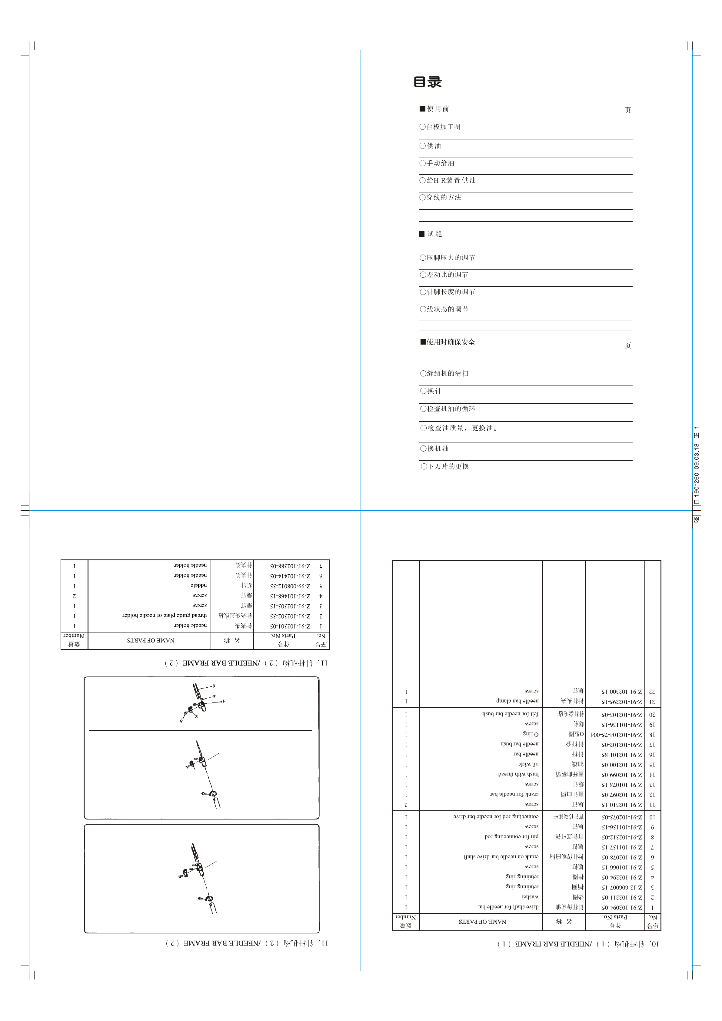
CONTENTS
BEFORE OPERATING
Schematic diagram of the machine table
Lubrication
Manual lubrication
Filling the HR device with silicon oil
Threading
TEST SEWING
Presser foot pressure
Diff.feed ratio
PAGE
1
2
3
4
5
6
7
Stitch length
Thread tension
MAINTENANCE DURING
USE
Cleaning the machine
Replacing the needle
Checking the oil circulation
Checking and replacing the oil filter
Checking the oil
Replacing the lower knife
8
9
PAGE
10
11
12
13
14
15
-31--30-
6
7
Page 3
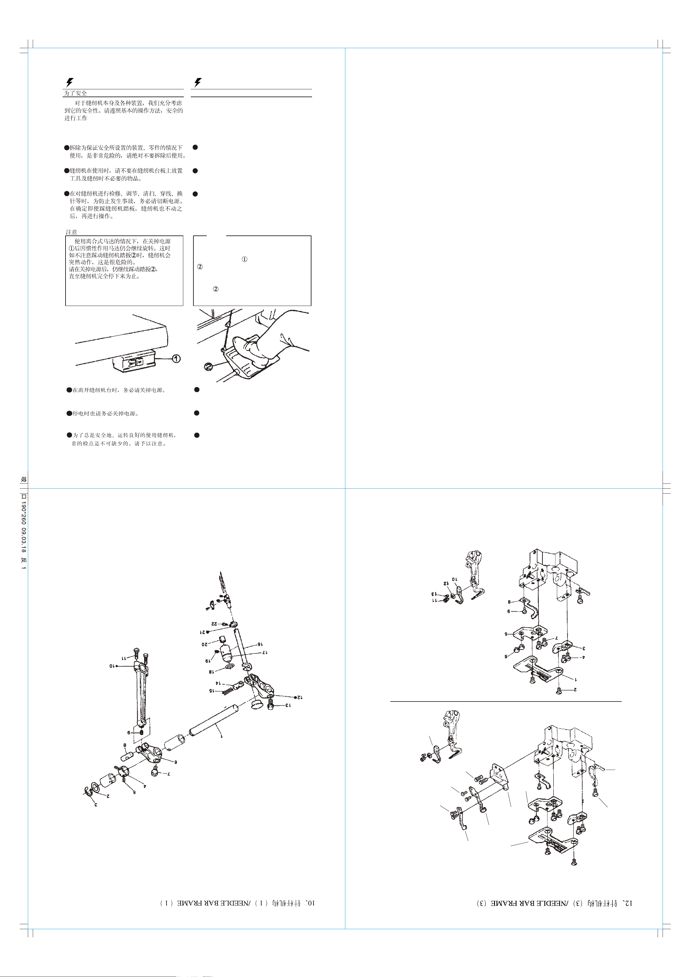
CAUTION
OBSERVE THESE SAFETY PRECAUTIONS
Though Pegasus takes the utmost care to
produce safe sewing machines and devices,
operstors should follow these basic safety
rules.
To prevent accidents,do not remove safety
devices or parts while operating the
machine.
Do not leave tools or other unnecessary
objects on the machine table while
operating the machine.
Before maintenance,adjusting,cleaning,
threading or replacing the needle,and to
prevent accidents,be sure the power is
turned off.Check that the machine will not
operate when the pedal is pressed.
Note
lncase a clutch type motor is used,it will
keep on rotating by inertia after turning
off power supply. lf the machine pedal
is stepped on inadvertently,it is
dangerous because the machine will move
unexpectedly.keep on stepping on the
pedal until the machine comes to a stop
after tuming off power supply.
Tum the power off before leaving the
machine table.
In the event of a power failure,be sure to
tum the machine off.
H
Check that the machine is securely
grounded.
-29-
-32-
24
23
22
21
20
19
16
18
14
17
15
Page 4

932 GAUGE PARTS LIST
Cut the table refeming to the diagram.
932 GAUGE PARTS LIST
55
70
80
86.3
115
Standard dimention
...........................................306mm
EFKA QUICK .......................334mm
Notes
Dimension for motors in Jopan....................................306mm
Dimension for EFK motor.............................................334mm
-60-
-33--28-
-1-
Page 5
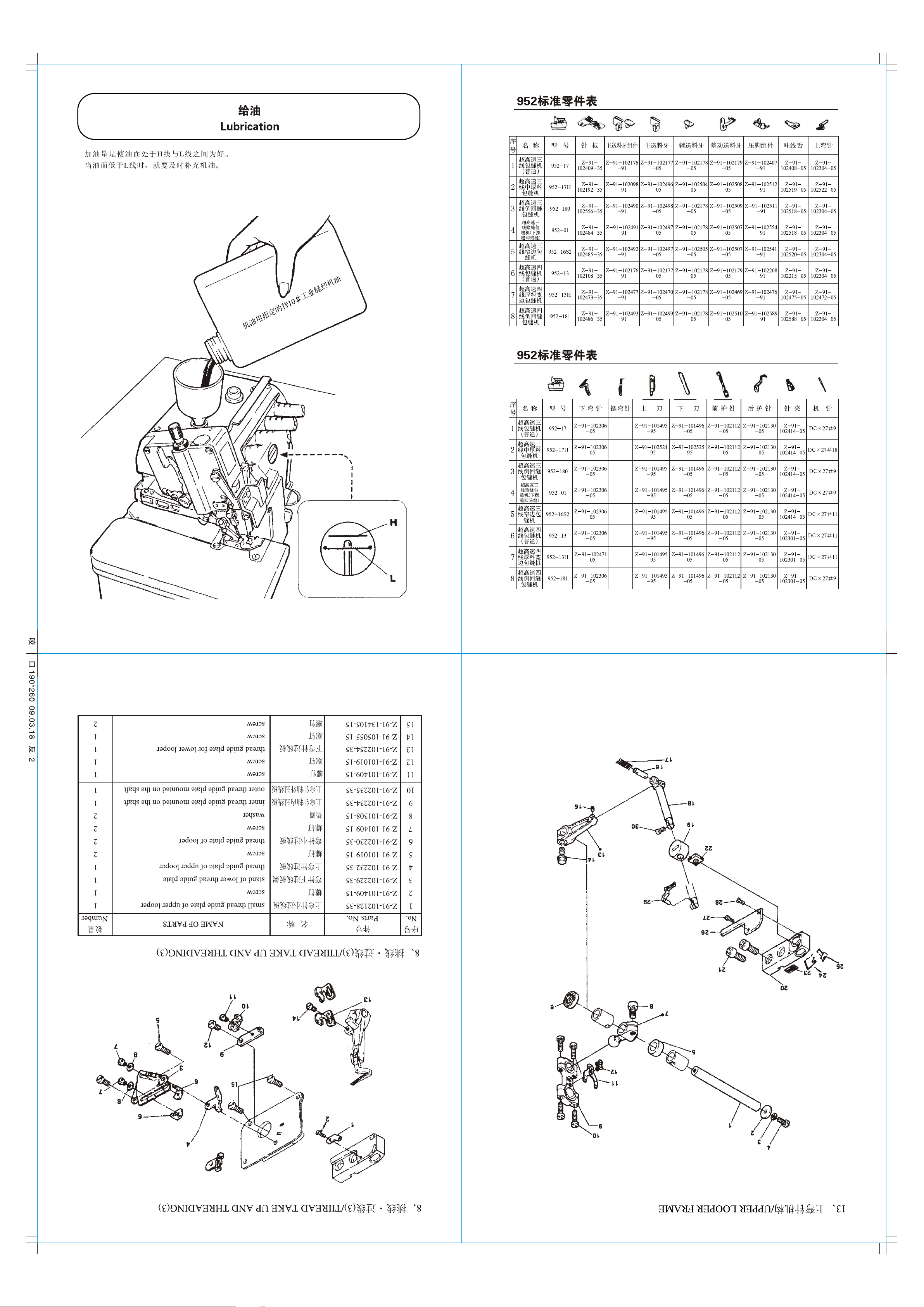
After filling the oil pan ,the top of the indicator
should lie between (H)and(L) lines.
Add oil, when the oil level indicator reaches or
goes below(L).
ocite oil NO.18
Mobil vel
932 ±ê×¼Áã¼þ±í
952 GAUGE PARTS LIST
952 GAUGE PARTS LIST
-2-
-59-
-34- -27-
Page 6
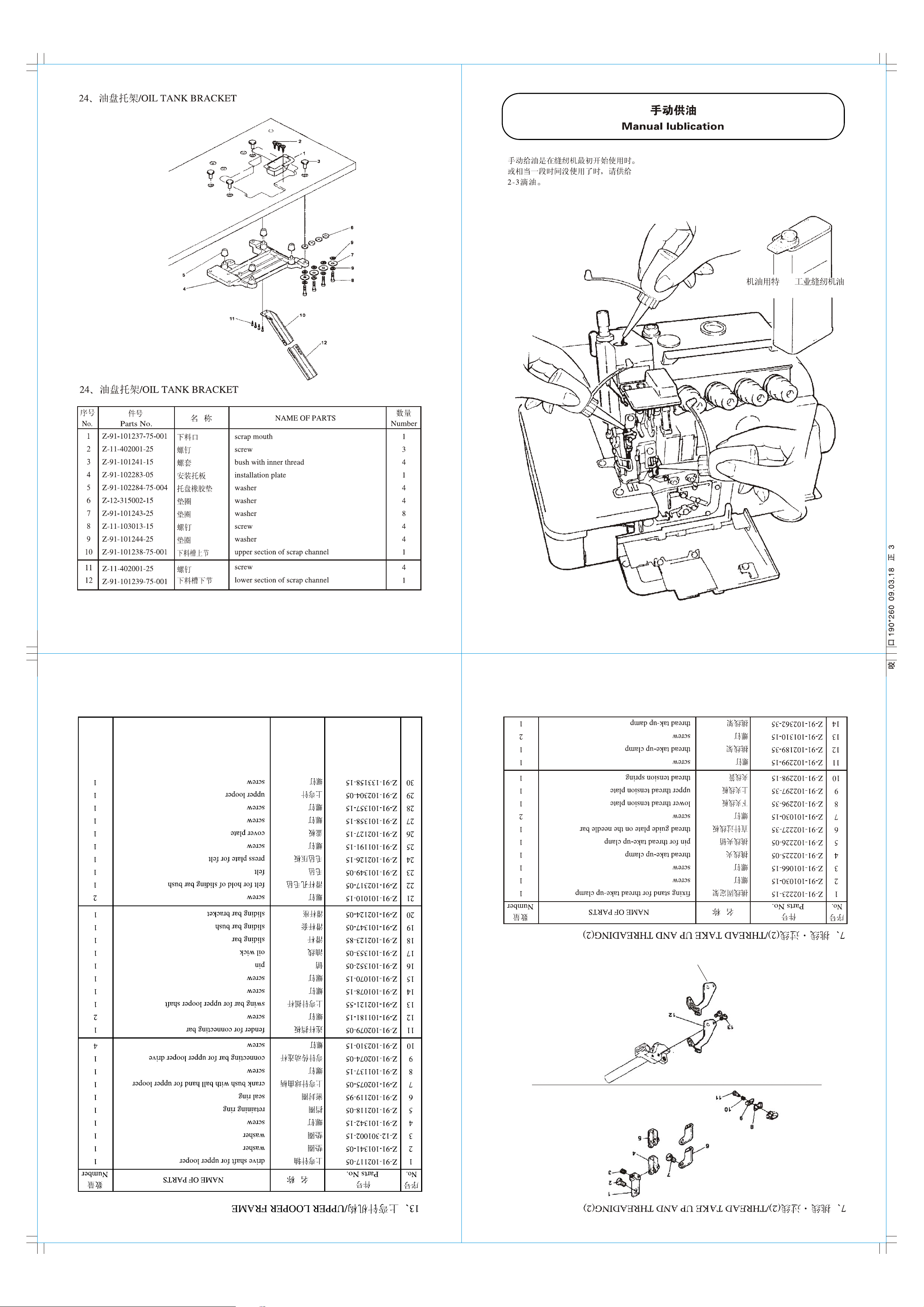
Apply 2 or 3 drops of oil by hand when the
machine is used for the first time or has been
left unused for some time.
18 #
Mobil velocite oil No.18
-58-
-3-
-26- -35-
14
Page 7

Fill the HR device with oil before it is too low in
order to prevent needle thread breakage and
fabric damage.
Note:Use Pegasus recommended silicon oil.
UNION CARBIDE CORPORATION
UCC L-45(10)
-4-
-57-
-25--36-
18
Page 8

Needle thread
Trim the knots off neatly
before passing through
the eye of the needle to
rethread.
Open three covers.
Sewing the presser foot aside.
Knot the preset thread and the
thread being used together to
thread the machine.
Looper thread
Trim the knots off neatly
after passing through the
eye of the looper
-5--56-
Make sure the machine is
threaded correctly by referring
to the threading diagram.
Threadlng diagram
-37-
-24-
Page 9

Light
Loosen sdjusting nut and turn adjusting nut
to adjust the presser foot pressure. Is should
be as light as possible.yet be sufficient to
obtain the proper stitch formation.
Heavy
18
18
-6-
-23--38-
-55-
Page 10

Loosen the adjusting nut and tum the
adjusting nut to adjust the dlfferentlal
feed ratio.
-54-
To shrink
To stretch
-7-
-39--22-
31
33
32
34
Page 11

While pressing the push button , turn the hang-
wheel to seek the position at which the push
button goes further into the depth.
Then, keeping the push button pressed,
turn the handwheel and set the desired
scale to the aligning mark.
Ailgning Mark
Coarse
Note: Stitch length adjustment must only be
made after the differential feed ratio
has been changed.
Push Button
Flne
Handwheel
-8-
-53-
-21--40-
Page 12

Make tension adjustments with the needle
thread knob the upper looper knob
and the lower looper knob .
To tighten
To loosen
-52-
-9-
-20- -41-
Page 13

Mainly the slots of the needle plate and the
feed rows should be cleaned.
-10-
-51-
-19--42-
Page 14

* Check the needle carefully to see that the
scarf is turded to the rear of the machine.
* Insert the needle to the proper depth,and
fasten securely.
Standard needle:Organ DC 27
E3200H 5200Hseries:Organ Dc 27
Scarf
-50-
-11-
-18- -43-
Page 15

Operating
-12-
-17--44-
-49-
Page 16

Check and replace the oil filter every six
months.
-13--48-
-16- -45-
Page 17

Replacing the oil one month after the firstuse
and every six months thereafter.(See p 2.)
Lower knife
plate
of the needleA
Top surface
-14- -47-
-15--46-
Chek cutting action of knife
Level of A Level of B
the lower knife B
Cuttung edge of
(See the right figure.)
Insert the lower knife
Tighten the screw.
holder slide to the right.
makes the lower knife
Loosening the screw
Tighten the screw.
Upper knife
drawing on the right figure.
Thin the hand wheel as the
To replace the lower knife
knife holder to the left.
after sliding the lower
Temporarily screw
Remove the lower k
Loosen the screw.
Loosen the screw.
the lower knife
Correct angles to resharpen
To remove the lower knife
 Loading...