

Page 1
Z..JBBOOA
HIGH-SPEED
OPERATION
LOCKSTITCH
SEWING
MANUAL
MACHINE
llllil·
ZOJE
PARTS
m
Jl
~il
SEWING
BOOK
~!11
mn
n~
fH
MACHINE
~
ae
CO.
~
, L
TO.
61
Page 2
INSTRUCTION MANUAL
To
get the most out of the many functions of this machine and operate it in safety, it is necessary
to use this machine correctly.
Please read this Instruction Manual carefully before use.
your machine for a long time.
Please remember to keep this manual in a safe place.
1.
Observe the basic safety measures, including, but not limited to the following ones, whenever
you use the mach ine .
2.
Read all the instructions, including, but
u
se
the machine, In
anytime when necessary.
3. Use the mach ine after it has been ascertai
valid
in
your country.
4.
All safety devices must be in position when the machine is ready for work
The operation without the specified safety devices is not allowed.
5. This machine shall be operated by appropriately-trained operators.
6. For your personal protection, we recommend that you wear safety glasses.
7. For the following, turn off the power switch
the receptacle.
7-1
For threading needle (s) and replacing bobbin.
7-2 For replacing part (s)
7-3 For repair work,
7-4 When leaving the working place of when
8.
If
you should allow oil, grease, etc. used with the machine and
with
your
eyes
contacted areas and consult a medical doctor.
or
add
skin
ition,
keep
of
needle, presser foot, throat plate, feed dog, cloth guide etc.
or
swallow
this
any
not
limited to this Instruction Manual before you
Instruction
ned
that it conforms with safety rules/standards
of
disconnect the power plug
the
working place is unattended.
of
such liquid by mistake, immediately wash
We
hope you will enjoy the use of
Manual
so
that you may read
or
of
the machine from
dev
ices to come in contact
in operation.
it
the
at
9. Tampering with the live parts and
is prohibited.
10. Repairing, remodeling and adjustment works must only be done
technicians or specially skilled personnel.
11
. General maintenance and inspection works have to
12. Repair and maintenance works of electrical components shall be conducted by qualified
electric technicians
Whenever your find a failure
Periodically clean
13.
or
under the audit and gu dance
thE
! machine throughout the period
of
dev
ices. regardless
any
of
electrical components, immediately stop the machine.
of
whether the machine is powered ,
be
done by appropriately trai
of
specially skill
of use
- 12 -
by
appropriately trained
ned
personnel.
ed
personnel.
.
Page 3
14. Ground ing the machine is always necessary fot the normal operation
machine has to be operated in an enviorment that is free from strong noise sources such
as high
15. An appropriate power plug has to be attached to the machine by electric technicians, Power
plug has to be connected to a grounded
-f
requency welder.
receptacle.
of
the machine. The
16. The machine is only
17. Remodel or modify
all the effective
remodeling
18. Warning hints are marked with the two shown symbols.
or
~
~
&
Clllowed
t11e
machine in accordance with the safety rules/standards while taking
safely
modification
measures. We assumes no responsibility for
Danger
l~ems
to
be
used for the purpose intended. Other used are not allowed.
of
the machine.
of
injury to operator or service staff
requiring special attention
damage
caused
by
-
13
-
Page 4

FOR SAFE OPERATION
~
&
I
I
1. To avoid electrical shock hazards, neither open the cover
for
the motor nor touch the components mounted inside the electrical box.
1. To avoid personal injury, never operate the machine with any
cover, finger guard
To
prevent possible personal injuries caused by being caught in the machine.
2.
your
keep
the motor
them.
3.
To avoid personal injury, never put your hand under the needle when you
turn
To
avoid personal injury, never put your fingers into the thread take-up cover
4.
while the machine is in operation.
5.
The hook rotates at a high speed while the machine is in operation.
possible injury to hands, be sure to keep your hands away from the vicinity
of
the
the machine when replacing the bobbin.
6.
To avoid possible personal injuries, be careful not to allow
the
To
avoid possible accidents because
7.
OFF
the
8.
If
your machine is equipped with a serve-motor, the motor does not produce
noise
start
To
avoid electrical shock hazards, never operate the sewing machine with
9.
the ground wire
0.
To
prevent possible accidents because
1
component (s
of
on
fingers, head and clothes away from the handwheel, V belt and
while the machine
"ON" the power switch or operate the machine.
hook
during operation. In addition, be sure to turn OFF the power to
machine
the
power
belt cover and the V be
while the machine is
of
the machine, be sure to turn OFF the power to the machine.
the power plug.
of
safety davices removed.
is
in operation. In addition, place nothing around
whe
n tiling/raising the
to the machine when tilting the machine head
lt.
at
rest.
for
the power supply removed.
),
tum
OFF
the power switch
mac
hine head.
of
abrupt start
To
avoid poss ible accidents
of
electric shock or damaged electrical
in
prior to
of
the electrical box
of
To
your
fingers in
of
the machine, turn
or
removing
due
to abrupt
the
connectrion/disconnecti
the
belt
prevent
-
14-
Page 5
CONTENTS
BEFORE
l.
INSTALLATION··············· · · · · · · · · · · · · · · · · · · · · · · · · · · · · · · · · · · · · · · · · · · · · · · · · · · · · · · · · · · · · · · · · · · · · · · · ·16
2.
LUBRICTION · · · · · · · · · · · · · · · · · · · · · · · · · · · · · · · · · · · · · · · · · · · · · · · · · · · · · · · · · · · · · · · · · · · · · · · · · · · · · · · · · · · · · · · · · ·17
3. ADJUSTING
4.
ATTAClfiNG
5.
SETTING THE
6.
THREADING THE
7.
ADJUSTING THE STITCH
8.
TIIR.EADTENSION······························
9.
TliREA
10.
11.
12.
13.
OPERATION·················································································
THE
AMOUNT OF OIL (OIL SPLASHES)
THE
NEEDLE·······································································
BOBB£N
INTO THE BOBBIN
MACHIN'E
HEAD····························································
CASE·······································
IN
THE
HOOK·················
LENGTH·················································
TAKE-UP
HAND
LIF"TER···
PRESSER FOOT
SPRING····································
····
··
··· ··· ···
PRESSURE····································································
ADJUSTING THE FEED
HEIGHT OF
THE
FOOT
·············
···
··· ··· ··· ···
...
··· ··· ···
TIMING····························································
DOG··································································
....
·····································21
..
·························
······
··· ··· ···
······
··· ··· ···
·· ···
..
·········
···
··· ···
······20
···16
·17
·19
···19
20
·21
···22
·22
···22
···23
14.
NEEDLE-TO-HOOK
15.
ADJUSTING THE HEIGHT OF THE PRESSER
16.
ADJUSTING
17.
INSTALLING THE
18.
ADJUSTING THE HEIGHT OF
19.
WINDING THE
20.
SPECIFICATIONS····················································································26
THE
RELATIONSHIP·························································
THREAD TAKE-UP
BELT
COVER··········································
THE
KNEE
FOOT
STROKE············································
LIFTER·········································
...
············
...
··················
· · · · · · · · · · · · · · · .. · · · ·
BOBBIN···········································································26
-
15-
···23
···24
·24
24
·25
Page 6
I Attention
required
before
operation
Attention:
To
avoid machine damaging
1.before using the machine for the first time,please clean it thoroughly, get rid
the dust and make sufficient lubrication.
2.make sure that
connected.
3.if the voltage in your country is different from the voltage
do not use
4
..
make sure the running direction
S.during the first month when using this machine,you should run it in the normal
speed or lower speed.
the voltage is right,and that plug and power source are correctly
it.
--------
or
some accident, please do remember:
of
this machine,please
of
the motor wheel is right.
----
----
------------
------
----~
of
all
Fixing
F
ig.1
Fig.2 Fig.4
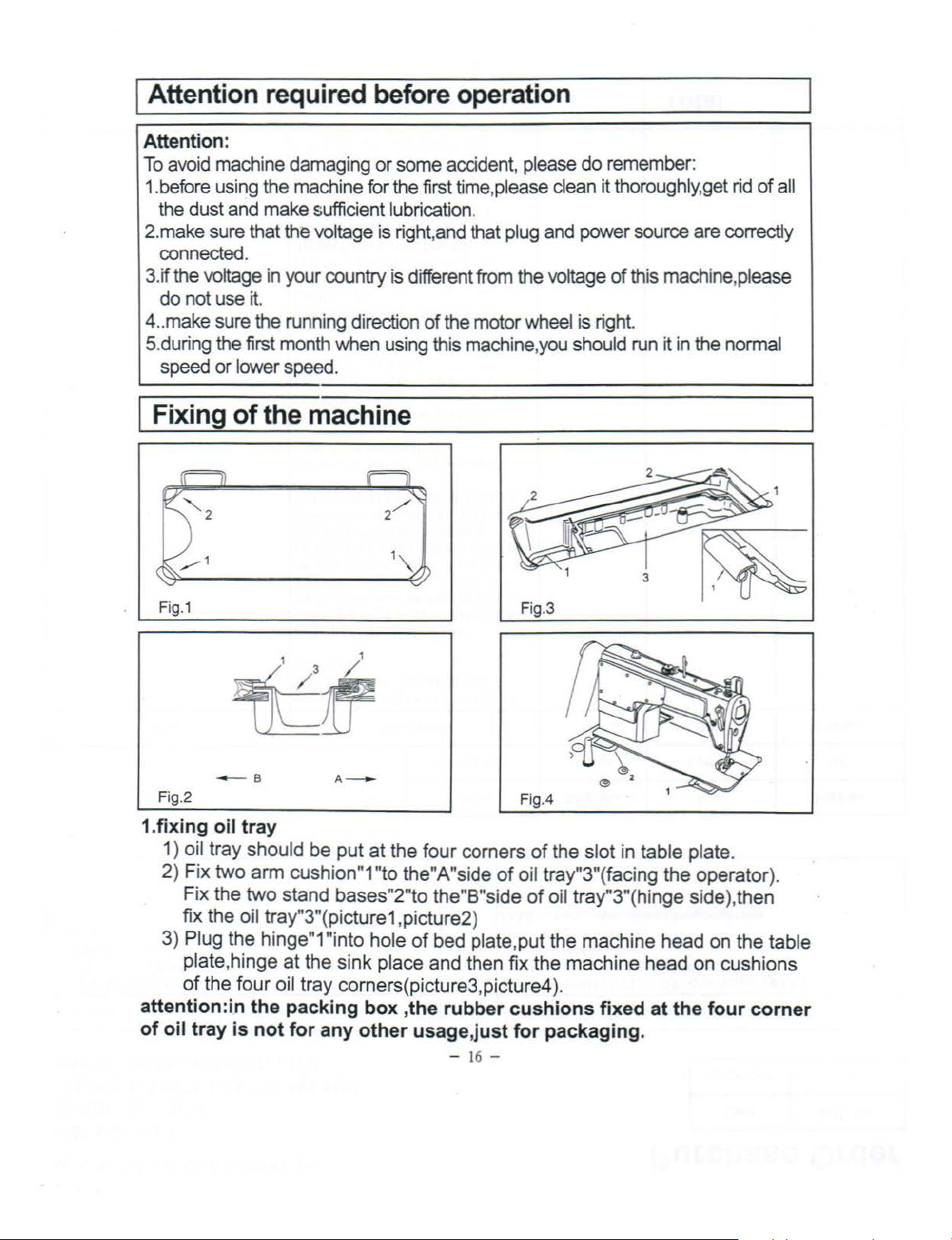
1.fixing oil tray
1)
2)
fix
3) Plug the hinge"1"into
plate,hinge at the
of
attention :
of
oil tray is not for any other usage,just for packaging.
of
the
machine
---
B A -
oil tray should be put
Fix two
Fix the
arm
cushion"1 "to the"A"side
two
stand
the oil tray"3"(picture1,picture2)
the
four
oil tray corners(picture3,picture4
i.n
the packing box ,the rubber cushions fixed at the four corner
at
the
bases
sink
"2"
hole
place and then
four
to
of
~~
corners
of
the"B"side
bed plate, put the machine head on the table
- 16 -
--------------
of
the slot in table plate.
oil tray"3"(facing
of
oil tray"3"(hinge side),
fix
the machine head
).
the
operator).
on
------~
then
cushions
Page 7
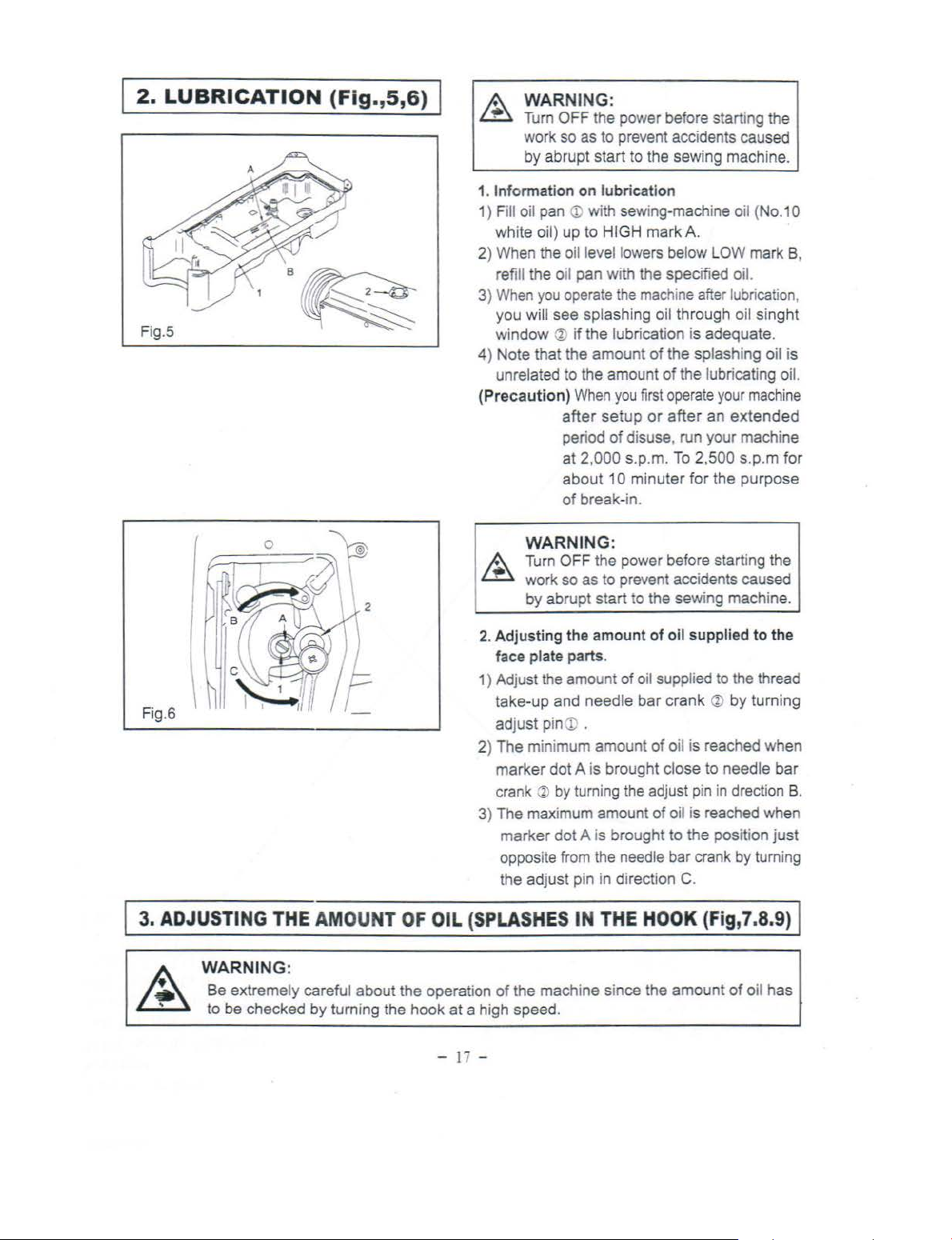
2.
LUBRICATION
(Fig.,5,6)
WARNING:
Turn
OFF
the power before starting the
work so as
by
abrupt start to the sewing machine.
Inf
ormation
1.
Fill oil pan
1)
white oil) up
2) When the
refi
ll
the oil
3) When
4) Note
(Precautio
you
you
will
window
that
unrelated to the amount
to
on l
ubricat
<D
with sewing-machine oil (No.1 0
to
HIGH
o
il
level lowers bel
pan
with the specified oil.
operate
see
splashing oil through oil
<»
if
the lubrication is adequate.
the
amount
n)
When
after
setup
per
iod
of
at
2,0
00
about
1 0
of
break-in.
WARNING:
Turn OFF the power before starting the
work
so
as
to
by
abrupt
start
prevent accidents caused
ion
mark
A.
ow
LOW mark B,
the
machine after lubrication,
singht
of
the splashing oil is
of
the lubricating oil.
you
first operate
or
after
disuse, run your machine
s.p.m.
minuter
prevent accidents caused
to the sewing
your
an
To 2,500
for
the
machine
extended
s.p.m
purpose
mach
ine.
for
Fi
g.6
I
3.
ADJUSTING
THE AMOU
NT
OF
OIL (SPLASHES
WARNING:
Be extremely careful about the operation
to
be
checked by turning the
hook
-
at
a high speed.
17
2. Ad
justing
face
1) Adjust the amount
take
adjust
2)
The
marker
crank ~ by turning the adjust pin in drection
3) The maximum amount
mark
opposite from the needle bar crank by turni
the adjust pin in direction C.
of
the machine since the amount
-
the
amount
plate parts.
of
-up and
minimum amount
er
needle
pin
eD
.
dot
A is brought close to needle
dot
A is brought
IN
THE
of
oil supplied
oil suppli
bar
HOOK
ed
to
crank ~ by
of
oil is reached when
of
oil is reached when
to
the
position
(Fig,7
of
the thread
to
the
turning
bar
B.
just
ng
.8.9) I
oil has
Page 8
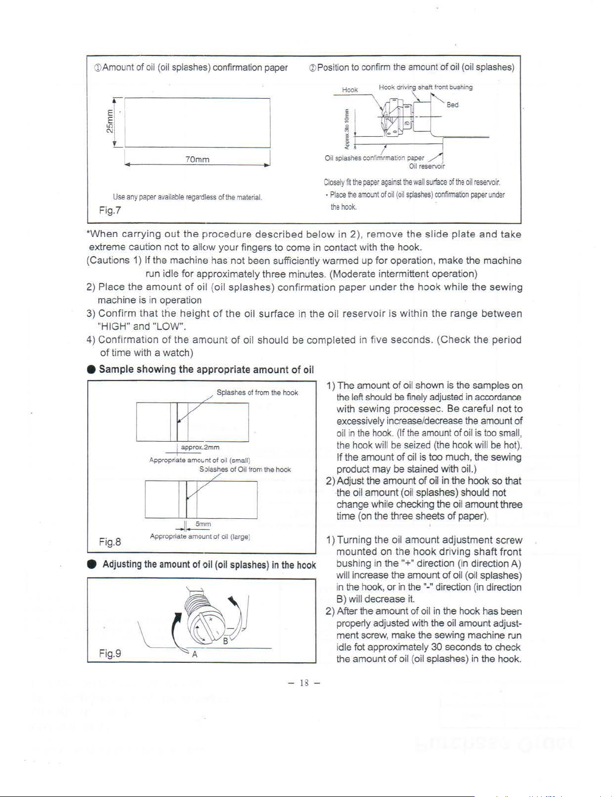
(!)
Amount
of
oil (oil
splashes) confi
rmation paper
~
Positio
n
to confi
rm the amount
of
oil (oil splashes)
~
r
~
~-
1
..
Use
any
paper
availab
le
Fig.?
*
When
extreme
(
Cautions
2)
3)
4)
e Sa
carrying
caution not
1) If the
Place
the
machine
Confirm that the hei
"HIGH" and "LO
Con
firm
of tim
e with a
mple showing
out
the
to
mac
run i
dle for
amount of oil (oil sp
is in
operation
W".
ation
of the amo
watch
the
[
1 1
1 approx.2mm
Appropriate
I I
--1
Ap
Fig
.8
propriate amount
e Adjusting the amount
Fig.9
~
70mm
regardless
of
the
procedu
all
ow
your fi
hine h
as not b
approximately
ght
of the
unt
of oil
)
appropriate
/s··~T~~hook
amo~on
t
of
oil (smal
S Jlashes of Oil from the hook
[L
1
Smm
of
on (large)
of
oil (oil splashes) in the hook
.,
1
Close
ly
· Pl
materia
l.
re
described bel
nge
rs to
come
een suffid
three
lashes) confirmation pap
oil
surface
sho
amount
l)
I
ently war
minutes. (Moderate intermittent
in
uld
be compl
of
oil
ace
the hook.
ow
in
in
contact
med
the
oil
eted
1)
The
the left should be finely adjusted in accordance
with
excessively increase/decrease the amount
oil in the hook. (If the amount
the hook will be seized (the hook will be hot).
If the
product
2)
Adjust
t
he
change while
ti
1) Turn
moun
bush
will increase the
in the hook,
B)
2) After the
properly
ment
i
dle
the
Hook Hook driving shan front bus
Sed
lit
the pape
r a
gainst
th
e w
all
surface
of
the
amount of
o
il (oil
splashes) confirmation
2), re
mo
ve
the slide plate
with
the
hook
.
up for
operation, make
opera
er under
reservoir is within t
in
amount
sewing
amo
the
oil
amount
me (on
ing
ted
ing in
wi
ll
decrease it.
screw, make
fat
approxima
amount
the hook whi
he
five
seconds
of oil
processec. Be
unt of oil is too
may be
amount
checking
the three sheets
the oil
on the
the
or
in the"-" direction (in direction
amoun
ad
justed with the oil amount adjust-
of
oil {oil splashes) in the
. (Check
shown
stain
(oil spl
amou
hook
"+" direction
amount
t of oil in the hook has been
tely
is the
much, the
ed
with oil.)
of
oil in
ashes
the oil
of
.
nt
adjustme
driving
of
the sewing machine run
30
seconds
hin
g
the
oil reservo
ir.
paper und
er
and
take
the
machine
tion)
le
the
sewing
range
between
the
period
samples
careful
of oil
the
) should
amount
paper
(in directi
oil (oil splashes)
not
is too small,
sewing
hook
so
not
three
).
nt scr
shaft
front
on
to
check
hook
that
ew
on
to
of
A)
.
-
18
-
Page 9
I
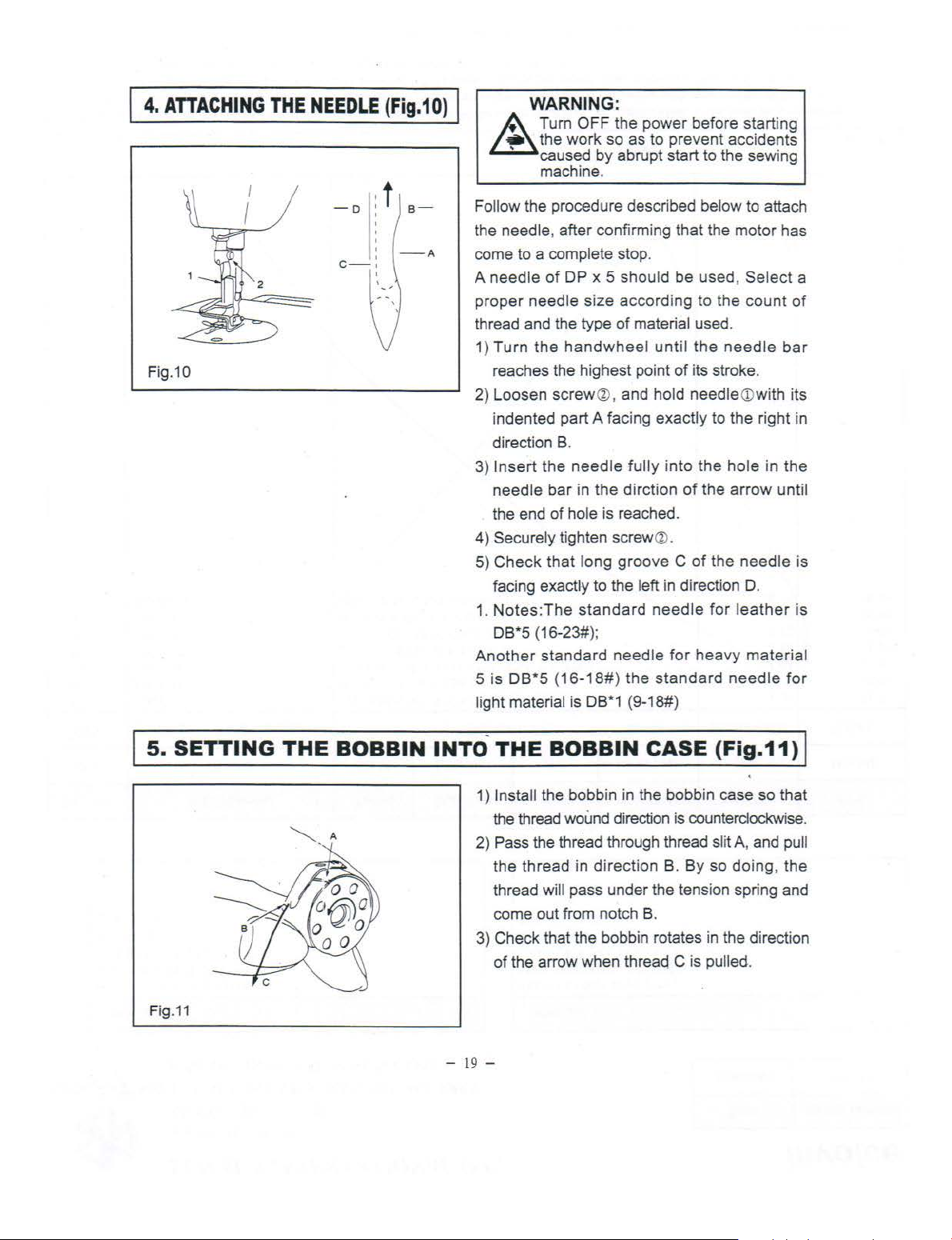
4.
ATTACHING
THE
NEEDLE
(Fig.10)
I
L.:1!::::::.
WARNING:
A Turn
the
' caused
machine.
OFF
work
the
power
so as
by
abrupt start to the sewing
before starting
to
prevent
accidents
Fig.10
-o
c-
Follow the procedure described below to attach
the needle,
I
,
I
I
come to a complete stop.
needle
A
proper
thread and the type
Turn
1)
reaches the highest point
2)
Loosen
indented part A facing
direction
3)
Insert
needle
the end
4)
Securely tighten screw
5)
Check
facing exactly
1.
Notes:The
DB*S {16-23#);
Another
5
is
DB*5
light material is DB*1 (9-18#)
after
of
DP
x 5
needle
the
size
handwheel
screw
B.
the
needle
bar
in
of
hole is reached.
that
long
to
standard
standard
{16-18#)
confirming that the
should
according
of
@,
and hold
fully
the
dirction
groove C of
the left in direction D.
needle
the
be used, Sel
to the
material used.
until
the
of
its stroke .
needle<Dwith its
exactly
®.
needle
standard
into
of
for
the
the
heavy
to the right in
the
for
motor
count
needle
hole
in
arrow
needle
leather
material
needle
has
ect
bar
the
until
a
of
is
is
for
I
5.
SETTING
Fig.
11
THE
~-
BOBBIN
A
INTO-THE
1) Install the bobbin in the bobbin case
the thread wound direction is counterclockwise.
2) Pass the thread through thread
the
thread
come
3) Check that the bobbin rotates in the direction
of
- 1
9-
BOBBIN
thread
the arrow when thread C is pulled.
in
direction
will pass under the tension spring and
out
from notch
CASE
B.
By
B.
(Fig.11)
sl
so
so
it
A, and pull
doing
, the
I
that
Page 10
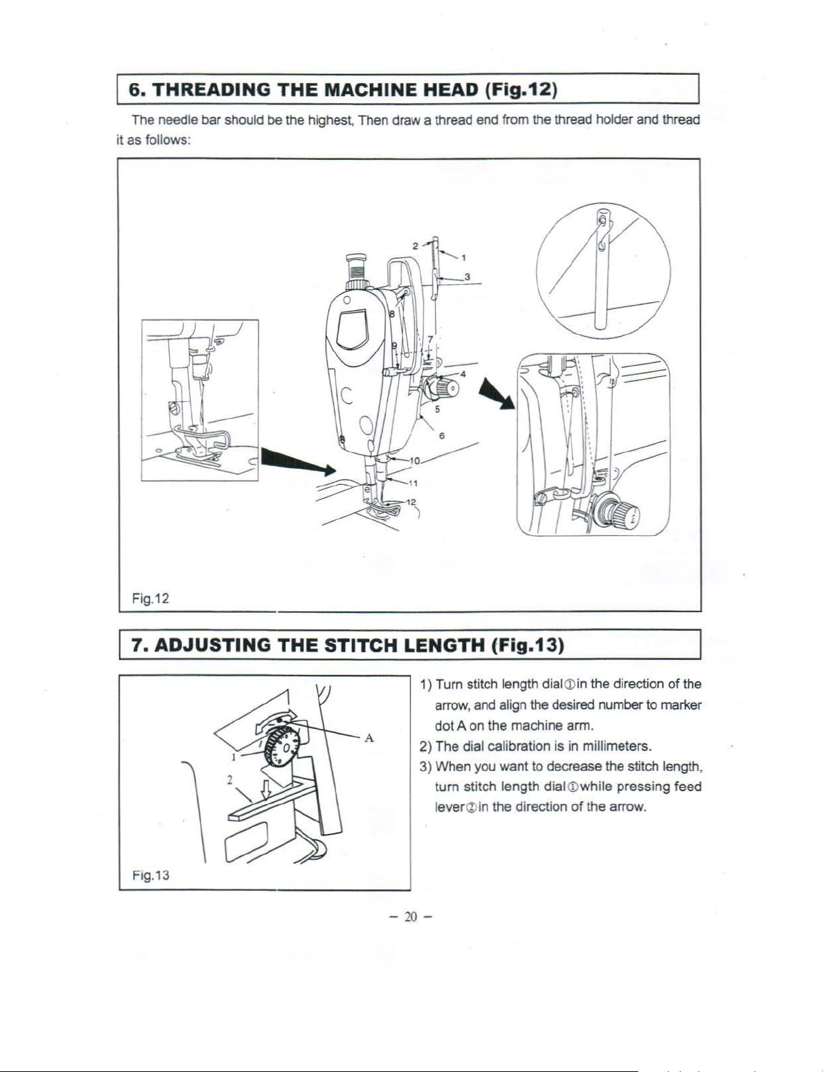
6.
THREADING
The needle bar should be the highest, Then draw a thread end from the thread holder and thread
follows:
it as
THE
MACHINE
HEAD
(Fig.12)
Fig.12
7.
ADJUSTING
Fig.13
THE
STITCH
A
LENGTH
1) Turn stitch length
arrow, and
dot
A on the machine arm.
2)
The dial calibration is in millimeters.
3)
When you want to decrease the stitch length,
turn stitch length
lever
a>i
-
20
-
(Fig.13)
dial <Din the direction
align the desired number to marker
diai<Dwhile
n the direction
of
pressing feed
the arrow.
of
the
Page 11
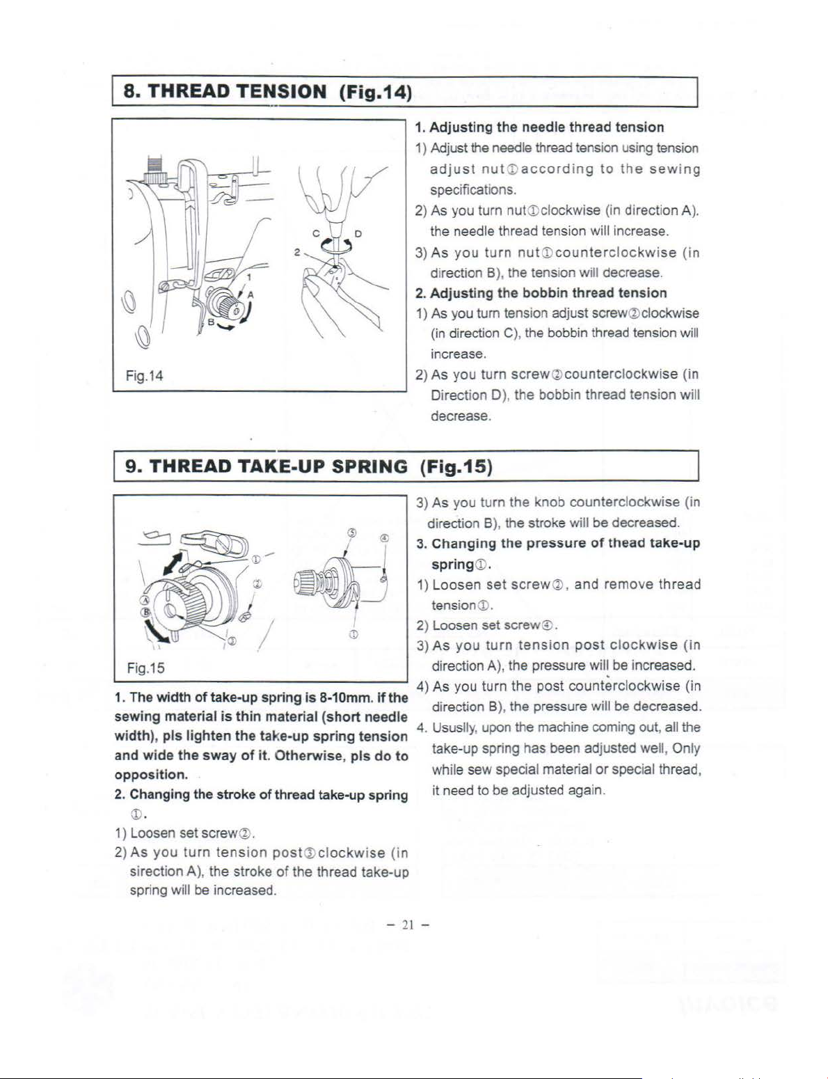
8.
THREAD
)
Fig.
14
TENSION
L------------------1
9.
THREAD
TAKE-UP
(Fig.14)
SPRING
1.
Adjusting
1) Adjust
adjust
specifications.
2) As you turn
the needle thread tension will increase.
As
you
3)
direction B
Adjust
2.
1) As you turn tension adjust screw
(in
direction C
increase.
2) As you turn screw
Direction 0), the bobbin thread tension will
decrease.
the needle thread tens
the
needle
nut<Daccording
turn
ing the bo
thread
tension usi
to
nutCDclockwise (in direction A
nut<Dcounterclockwise (in
), the tension will decrease.
bbin
thread tension
),
the bobbin thread tension will
(bl
counterclockwise (in
ion
ng
the
sew
(%)
clockwise
tensi
(Fig.15)
on
ing
).
3) As you tu
directi
Changing
3.
spring CD.
1) Loosen
tensioneD.
2) Loosen set screw® .
3)
As
Fig.
15
of
1. The width
· t ·
sewmg ma
'
dth
) 1 I'
WI , p s
wide
and
oppos
ition. while sew special material
2. Changing the stroke
<D
.
1) Loosen set screwQ).
2)
As
you
sirection A
ng
spri
take-up spring is
·
1
ena
IS
ht
19
en e a e-up
the
sway
turn
tension post
),
the stroke
will
be
increased.
th
· t .
m ma
th
t k . t . 4. Ususlly, u
of
it. Otherwise,
of
thread take-up spring it need
of
8-1
Omm. If
( h direction B
1
ena s ort
spnng
(]) cl
ockw
the thread take-up
the . . .
needle
ens1on . .
pis
do
ise (in
direction A
4) As you turn the post counterclockwise (in
to
take-up spnng has been adjusted well, Only
rn
on
B), the stroke will be decreased.
the
set
you
turn
),
),
pon
to
be adjusted again.
the knob counterclockwise (in
pressure
screw
tens
the pressure
the pressure
the machi
of
thead
Q),
and remove thread
ion
post clockwise
wil~
be
increased.
Will
be decreased.
ne
comi
ng
out, all
or
special thread,
take-up
(in
the
- 2
1-
Page 12
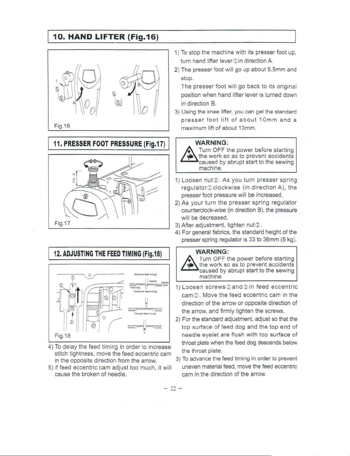
10.
Fig.16
HAND
LIFTER
(Fig.16)
1)
To
stop the machine with its presser foot up,
turn hand
2) The presser foot will
stop.
The presser foot
position when hand lifter lever
in
direction
3) Using the knee lifter,
presser
maximum
lifter lever<Din direction
go
up about 5.5mm and
will
go
back to its original
is
B.
you
can get the standard
foot
lift
of
lift
of
about 13mm.
about
1 Omm
A.
turned down
and
a
1
11.
PRESSER
Fig.17
12.
ADJUSTING
Fig.18
To
delay the feed timing
4)
stitch tightness, move the feed eccentric cam
in the opposite direction from the arrow.
if
feed eccentric cam adjust too much, it will
5)
cause the broken
FOOT
PRESSURE
THE
FEED
of
needle.
(Fig.17)
TIMING
in
(Fi
g.18
order to increase
I
WARNING:
A Turn OFF the power before starting
~
1)
2)
3) After adjustment, tighten
4) For general fabrics, the standard height
)
~
1)
2)
3)
the
work
so
as to prevent accidents
caused by abrupt start to the sewing
machine.
Loosen
regulator<Dclockwise
presser foot pressure will
As
counterclock-wise
will be decreased.
presser spring regulator
nutQ).
you r turn the
As
you turn
(in
presser
(in
direction B
is
nut@.
WARNING :
A Turn OFF the power before starting
the
work so as to prevent accidents
caused
machine.
Loosen
cam<D. Move the feed eccentric cam in the
direction
the arrow, and firmly tighten the screws.
For the standard adjustment, adjust so that the
top surface
needle eyelet are flush
throat plate when the feed dog descends below
the throat plate.
To
advance the feed timing in order to prevent
uneven material feed, move the feed eccentric
in
cam
the direction of the arrow.
by
abrupt start to the sewing
screwsa>andO)in
of
the arrow or opposite direction
of
feed dog and the top end
with
presser
direction A),
be
increased.
spring regul a
),
33 to 36mm (5 kg).
feed
top surface
spring
the
tor
the pressure
of
the
eccentric
of
of
of
-
22-
Page 13
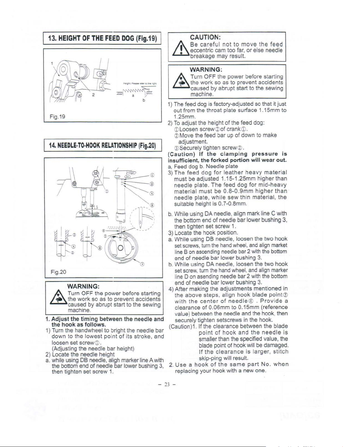
13. HEIGHT
Fig.19
14. NEEDLE-TO-HOOK
Fig.20
OF
THE
FEED
DOG (Fig.
RELATIONSHIP
I
~
=s_---
-
"""
I I
....__.
~
·.·.-_-_
-_.
t.·. ' ; ,
(
Fig.20
~
-- - ®
, I -.
,'
~
:
~
0 I
' '
...
-
..
-
19)
)
@
'D'
.;>
G
'.
:
WARNING:
A Turn OFF the power before starting
~
1.
1) Tum the handwheel to bright the needle bar
2) Locate the needle
a. whi
the
work
so
caused by abrupt start to the sewing
machine.
Adjust
the
down
loosen set screw
(Adjusting the needle bar height)
the bottom end of needle bar lower bushing 3,
then tighten set screw
the
timing
hook
as
to
the lowest point
le
using DB needle, ahgh
as to prevent accidents
follows
CD
heigh~
between
.
.
the
of
its stroke , and
marl<er
1.
needle and
. .
hne A w1th
CAUTION:
& Be
careful not
eccentric cam too far,
breakage may result.
to
move the
or
else needle
feed
WARNING:
~
1) The feed dog is factory-adjusted so that it just
2)
(C
nsufficient, the
i
a Feed dog
3)
b. Wh
3)
a. While using DB needle, loosen the two hook
b. Wh
4) After making the adjustments mentioned
(Cauti
2.
Turn
OFF the power before starting
the work so as to prevent accidents
caused by abrupt start to the sewing
machine.
out from the throat plate surface 1 .15mm to
1.25mm.
To
adjust the height
CD
Loosen screw@
®Move
~
autio
The
must be adjusted
needle plate .
mater
needle
suitable height is
the bottom end
then tighten set screw 1 .
Locate the hook position.
set
li
ne B on
end
set
li
ne D on
end
the above
with
clearance
value) between the needle and the hook, then
securely tighten setscrews in the hook .
Use a hook
replacing your hook with a new one.
the feed bar up
adjustment.
Securely
il
e usi
screws, tum
of
il
screw,
on)1.
tighten screw
n)
If
the
b.
Needle plate
feed dog
ial
must
plate ,
ng
DA needle. align
ascending
needle bar lower bushing 3.
e using DA needle, loosen the two hook
tum
asending
of
needle bar lower bushing
steps
the
center
of
If the clearance between the
point
smaller than the specified value, the
blade point of hook will
If
the
skip-ping will result.
of
the feed dog:
of
crankeD.
of
down to make
(%)
.
clamping
forked
The
while
of
the
the hand
0.06mm to 0.15mm (reference
of
portio
for leather
1.
15-1.25mm h1gher than
feed dog
be
0.8-0.
sew
0.
7 -0.8mm.
needle bar lower bushing 3,
hand
whee
needle
whee
needle bar 2
, align
of
need
of
hook
clearance
the
same
pressure
n
will
wear
heav~
9mm
thin material,
l,
bar 2 with
l,
hook
le® .
and
is larger, stitch
material
for mid-heavy
higher
marl<
line C with
and ali
gn
the
and ali
gn
with
the
3.
blade point@
Provide
the
needle
be
damaged.
part
No.
is
out
than
the
market
bottom
marker
bottom
bla~e
when
in
a
IS
-
23
-
Page 14

15.
ADJUSTING
THE
HEIGHT
OF
T.HE
PRESSER FOOT (Fig.21)
WARNING :
A Turn OFF the power before starting
~
the
' caused by abrupt start
work so as to prevent accidents
machine.
to
the sewing
Fig.21
16.
ADJUSTING
Fig.22
THE
1) Loosen setscrew
foot height and the angle
2) After
(1).
ad
justment, securely
X;
. And adjust the presser
of
the
presser foot.
tighten
the
THREAD TAKE-UP STROKE (Fig.22)
WARNING :
A Turn O
~
1) When sewi
thread
increase the length
the thread take-up.
2) When sewing light-weight materials, move
thread
to
the thread take-up.
3)
way
center of the screw.
the
' caused by abrupt start
machi
decrease the length
Normally, thread guide<Dis positioned in a
that marker line C is al igned with the
FF
the power before starting
work so as to prevent accidents
ne.
ng
heavy-weight materials, move
gu ideCDto the le ft in direct ion A to
of
guide<Dto the
of
to
thread pulled out by
right
in
thread pulled out
set screw
the sewing
direction
B
by
17.
INSTALLING
Fig.23
THE
BELT COVER (Fig.23,
1.
Installation procedure
Drill four guiding holes A and B for wooden
1)
2)
fi
I
3)
I
liT
4)
5) Fix belt cover
-
24
-
screws
Install
hole
Pass the handwheel through the hole
cover A
arm. At this time , you can smoothly
th
han
illustrated
Place
and B.
®,
screw®with
in
the table.
belt
in
arm.
Q),
e handwheel diagonally
dwhee
in the figure.
belt
(i)and
washer
24,
25)
cover
then set the handwheel on the
l by tiltin g be
cover BQ;
supportCDin the
from
the rear
lt
cover AQ)
on guiding
AQ)on the arm using screws
@,
At
this time, tighten
a t i
ghtening
taped
in
install
holes
torque
of
belt
the
as
A
of
Page 15

Fig.24
Fig.25
1
18.
ADJUSTING
THE
HEIGHT
of
30
kgf
/cm
and
torque
screws, the securing state
not change.
6)
Warnings:1)
OF
of
25 kgf/cm. If you tighten further these
Move
belt
cover Ba:>
rubber section
contact with belt cover A
move the
by
0.5 to 1 mm. Now,
in
position using wooden screw and washer.
7)
Fit cat
THE
belt cover B in the same direction
For
safty's
should be installed.
(!)
to
the belt cover
KNEE LIFTER (Fig.26,
screw~with
of
backward E until the
of
belt
cover
fix
needs,
a
the belt cover will
B~comes
(l). Then, further
the
belt
A.
tightening
cover
belt
cover
27)
in
B
I
Fig.26
WARNING:
A Turn OFF the power before starting
~
1. The standard height of the presser foot
2) You can
3)
the
work so as to prevent accidents
' caused by abrupt start to the sewing
machine.
using the knee lifter
adjust
13mm using knee lifter adjust
When
you
have adjusted the presser foot lift
to over 1
of
not hit presser
Fig.27
Omm
needle bar a; in its
is 1 Omm.
the
presser
, be sure that the bottom end
lowest
footQ).
foot
lift
screw
<D
position does
lift
up to
..
ed
-
25
-
Page 16

19.
Winding
20.
SPECIFICATIONS
the
------
bobbin
----
----------------
Thread
bobbin thread onto the bobbin
in t
he
figu
the
re 28.
bobb
in
----
winder
--------~
and
wind
the
as
illustrated
Application
Max Sewing
Speed
Max Stitch
Length
Lifting
height Lifter
of
presser
r fool
Hand
Knee
Lifter
Needle
L
Lubrication oil
Motor power
1.
While Sewing Light materials, the machine
dog and do some adjustment.
2.
Machine with "R" added is using roller presser foot.
For Light mediumheavy materials
5500 RPM
mm
5
6mm (MAX.) 6mm (MAX.) 8mm (MAX.)
13mm (MAX.) 13mm (MAX.)
9#-18#
DBX1
.
need
For heavy materials I
I
3000 RPM
8mm
DPX5
16#-18#
White oil No.1
370W
to
change the presser foot, needle bar and feed
0
For Leather
materials
3000 RPM
8mm
13mm (MAX.)
DPX5 20#- 23#
-
26-
Page 17

To
order
or
further information , please contact:
* Please
when necessary.
* The description covered in this instruction manual is subject to change for impr?vement
the commodity without
do
not hesitate to contact
not
ice.
our
distributors
or
agents in your areas for further information
-
27
-
of
Page 18

•itt::J.M
PARTS BOOK
The machine with "R" added
Please confirm the relative applications Ref.No,
When buying the
parts
.
is
using roller presser foot.
part
no.
-
28-
Page 19

CONTENTS
1.
ffl~5J'ffi.i
2.
3:.~J1.:}jt~ff5J-ffi.f4:
4:
Machine Frame & Miscellaneous Cover Components·· ................... 30
Main
Shaft & Thread Take-up Lever Components .... ........... 33
Driving Shaft Components ... ......... .......... .............. ................................ .......
4.
ffiM415J-ffi.f4:
5.
~*451-ffi.i4:
6.
fji]~5J-~14:
7.
~filft5J-ffi.f4:
8.
&:iW~~i1~~51-~fH4:
9.
~~R~~ffiM411fJ.1H4:
10.
~f4:
Presser Foot Components ....... .......
Feed
Mechanism Components ..............
0il
Lubrication
0il
Reserv
Accessories
........................... ................................... ...........
Co111ponents ...........
oir
Components ............... .........
Belt
Cover & Thread Stand Components .................... .... 47
Modei"R
"
Presser Rollar Special Accessory .....................
..................................
...
.....
.............
..........
........
········· ........ .......
......
..... ....
..................
.. ..
.........
.........
.... ..... .
.......
35
39
40
.
43
45
49
51
-
29
-
Page 20

1,
m767t!L-flf
Machine frame & miscellaneous cover components
8
35
f
3e r
--
-------2Y
I •
I
0
l3s:5LC) l
I I
I
39
I
140
---
L
__________
•>
b-._
~
- I
,,
I
I
I
J
-
30-
74
Page 21

1
~
m~
Ff~
REF.
~p.
{4:
PART
2.10GR101
I
240GOIOI
2
GS159-8
3
GR679n
4
'
GR585-8
5
()
GR584-8
GS300-8
7
8 240GRI02
9
24000102
10
GR586-8
GR587-8
11
12
GR611·8
GRS00-8
GR602-8
13
14
GQ200-8
15
GS310.8
16
GS310.8
17
GR603-8
18
GS313-8
19
.!0
GL23~-8
21
GR609·8
G\
22
GW202-8
23
GW608-8
24
GR607-8
GS314-8
25
GW183-8
26
27
GR606-8
28
GS315·8
29
GS316-8
30 GX200-8
31
G~1166-8
G.MI73-8
32 GS338-8
33
GS604-8
34
GS313-8
35
GR583·8
36 GS300-8
37 GM167/4-8
38 GM!68-8
39 GWI90-8
7tm
1lf
~
~o.
-s
\-'
184-8
Machine frame & miscellaneous cover components
fi:Q
li
.t
DESCRIPTION
iiitfi Face plate
iiH!H~
llJj~tfitltJ
jjj;flj!lJiTtlltti1ftH!f:
titl~fflft.,1l
ttfflll!
.15\UHitr
€m';f1i
J<iS~.H~
~~~~
r~li1L
i:t~~
i:ttiltE Needle thread guide pin
=.mt&tE
tl:ltl!f!iff-AA!
it~ff!)!l_;f;~
=:.!tlf&~tlfT
:b~~
~~~ilfT
~tiittfl-14'
~HH.Illl.
~til$1Ji;I.J
~~-
~~1fTen~ion
~~ttl
~~Ui
~tltlfr
~~-
tf5tUh'lli'il!li
;t~jJtJ'~iUltJ
~tUUinJ
f'~~U
tttti
:-\eedle
tt~
:\eedle
fttljtltf
tr:t&tl:l
tr:~~iltT
iii~~"lit!R*
iiii!itltT 3/16" x 28
tli!i$-14' Bed slide ASM. I
tt~
Slide
tttti•
AS~
.
Face plate gasket
S~ll/8
"
X44
ARM oil
. Rubber plug
li'i~1L*
SJ;.ring
Rubber plug
SM3/16" X
Side plate
Gasket
if~L*
Rubber plug
* Rubber plug
.t'eedle thread guide pin
Three-hole thread eyelet
Earthing indication
5~!3/16
'
SM3/16
" X
Arm
thread
guide-Ring
SMII/64"X40L=6
Thread
tension AS:M.
Tension
i!i
Tension
Ter
Tension Disc
Screw
Take-up
Thread
11/64
AR.\1
nut
Tension
Spring
Spring
.sion Disc
spring
Tesion
S~19
Screw
release
plate
plate
"
X4
0W.5
thread
ll/64"X40L=6
Rubber
L--9
plate
of
slide plate I
L=4
Sere"
sh.ie
ld ASM.
281...--9
Sere.,.
X
28
L=6
28
L=6
Screw
Screw
Disc
stopper
stopper
post
socket
64
''
pin
Screw
guide-left
Screw
plug
Screw3/
~
1/8
" X44
3/16"X!8
plate
Saew
3/16"X28
3/16
" X
II/
164"X40L=6
Screw
9
64
11/64" x4()
ll/64"X40L=6
16"x28
L=4
28
"
W.5
L=9
QTY
1...--9
L=6
L=6
medium-heavy
1
I
I
I
2
I
8
I
I
1
I
1
I
I
1
I
I
I
I
1
I
I
I
I
I
2
I
I
I
I
I
I
I
I
2
I
I
2
3
I
,
*"~
For
Light
materials
*
* *
* *
*
*
*
*
*
*
*
*
*
*
*
* *
*
* *
* * *
* *
*
*
*
* *
*
* *
* *
* *
*
* *
*
*
* *
*
*
*
* *
*
* * *
*
.1Jt4
For
heavy
materials
*
*
*
*
*
*
*
* *
*
* *
*
*
*
*
* *
* *
*
*
* *
* *
* *
*
*
*
*
.!t¥1'4
For
leather
materials
*
*
*
*
*
*
*
*
*
*
*
*
*
*
*
*
*
*
*
*
*
*
*
*
*
*
*
*
*
*
-
31
-
Page 22

1..
ff1%7tm.
.*%
REF.
Np.
i4:
PART No.
GS339·8
40
41 GS299-8
GS724-8
42
GS373·8
43
24008102
44
GK153-5
45
GK162-8
GQI%-8
46
47
GR1428-8
48
GS705-8
49
SOIGB107
50
SS-4080440
51
501BJI03
50181104
52
SOIGBI14
53
501GWI04
54
501GL103
55
56
501GL104
57
501BJI01
58
501GB113
59
501GK104
501GW103
60
61
501BJ102
62
501GB
63 501GB I 10
501GBI12
64
65
501GFI18
SOIGWIOI
66
67
50JGW102
68
501GK102
69
SO!GK!03
70
501GKI05
71
SOIGFIIO
72
50!GS109
73
GQ139-8
74
GX186-8
flt:
Machine
%
tl~i
UT
3132" X
~~~
lt
Bed screw stud
RHil~Jl
m1!!:~Jltur
!r!~~
tlUUfJIJi~~
itf:UfJIJi~~
~~tli;;f-~
0~1!!!
~Ill
~lll
~tl~JJII~tln
~ill~~-
.Pi:tlllii!:llfll:
:'.IE~~
:'R:t&Jt
1!-*f~tlt.liU:
~f&t.liU:
~f&B
~i;f.J~
ri~
~;t;~·
~{.·fii~f*!:li
III
~~~1!1:~
fii~~M
li!$ll~
It~~
~1!!:*~•
~tiH!BIItJf
fii~-~
~~5tli;!Jt!i-fflle
~f&ittltl8~-~l!!
fii~-0~111
~U
;!IL~~
;!IL~~WtJ
Ruler plate
Model plate
Rubber ring
it~
1!1
tnr
~JJ
1bread
Thread tension disk
1bread
Kut
Bobbin winder
Bobbin winder shaft COMPL.
Jl
Wahser 2
Latch spring
Bobbin lever
Adjusting plate
Rubber ring
Cushing I
Screw
Number plate
frame & mi
~
DESCRIPTION
56
L=l.9
Screw3/32"
Ruler plate screw
1bread
take-up lever cover
1bread take-up
Safety-indicanng plate
Screw
cutter
Screw
Bobbin
thread
Bobbin thread tension rod
tension spring
Tbread tension nut
ASM
Bobbin fitting bas'.s
fll:
Bobbin winder regulator I
Long spring
Short spring
Retaining riLg
E-ring
0-ring
Pole
scellaneous cover components
fit\
x56
lever
co,·er
tension ASM.
ASM
. 1
COMPL
flit
QTY
L=1.9 2
. I
. I
rt,
medium-heavy
4
1
2
1
I
I
l
I
3
1
2
I
2
1
I
I
I
I
1
1
I
I
1
1
1
I
1
1
1
'FJJ:tsl-
For
Light
materials
*
*
JJ:tsl-
Forheav:y
materials
* *
*
* *
*
*
*
* *
*
*
*
*
*
* *
*
*
*
* *
*
*
* *
* *
*
*
*
* *
*
* *
*
*
* *
* * *
*
*
*
*
*
*
* * *
* *
* *
*
*
*
*
*
*
* *
* *
* *
* *
* *
* *
*
*
*
Jt1j[f4
For
leather
materials
*
*
*
*
*
*
*
*
*
*
*
*
*
*
*
*
*
*
*
*
*
*
*
*
*
*
-
32
-
Page 23

2
~ ±$11l&~E~ff7t!l.
1It:
Main shaft & thread take-
up
lever components
6------13
~14
27
-
33
-
Page 24

2,
±
~lk~~ff~m
'flf
Main shaft & thread take-up lever com
pon
ents
14
1¥-+5
REF.
:t\o.
I
2
3
4
5
6
7
8
9
10
II
12
13
14
15
16
17
18
19
20
21
22
23
24
25
26
27
28
29
30 GR590-8
31
32 GR591-8
33 GS311-8
34
35
-i5
PART No. DESCRIPTION
GX199-8
GR59612-8
GS308-8
GR595-8
GH2l2-8
GH212-8
GH21<W4-8
GH35<W4--8
G0265-8
GH20812-8
GH35212-8
GH213-8
GS309-8
GS30--8
GH349-8
GH207-8
GRI6i
GR592-8
GS371-8
GTI56-8
GTI59-8
GS332
G0256-8
GR588-8
GR650-8
GR589-8
GS305-8
G0259-8
GXI98-8
G0258-8
GS306-8
GR638-8
GR808-8
240GP101
GS3Q.1-8
GZ229-8
G0261-8
GP172-8
GS709-8
tltliUfti'Hlll~
tttliUfmlltl~
tl~i:Uflitlfrl5
t~UUfi!E!lli
tfe~li:ff
tlt&itff
tltli!ff~~
fl~ilff~~~
~f&ffiatt~~
tlf&lll!tili$f/f Needle bar crank
!t~lll!fililfll'f!F
tt:ffit:ff
fl~lll!ti'iti'.llUUJ
ttff
ttff
ttffllllti'i
-8
!tf&lll!f1li~fittltT
~-tfr*ltTO~I!!i
ttfflll!ti'i~{t!t:UT
)lifl(Q.C.
ili*HiiH.
-8
iliflU11.C.•$01fJ
£~.Ia~~
J::~l'lbf;t
ff;
.lf
J::
~t\1
J:$1!t\ll!!llfJ l/40X40L=6 Screw
J::~nl~·
S!Wil'lb•i.ll~~
l:~lf>~·
.H!rlf>~gtltJ
ili-~fa·C.·~MVi
~*'1-fa.C.
_t~
J:~tltr
_t$!!!
!la1i'il'IBARUi!JfS
111!1i'il'lllfili.ll'i'HIH~
lll!filiii!J•ilfiH¥10~1!1
Uli·C·~
~f&±#J~
~f&±~~~~tUJ
~Oil
l11read
Thread take-up bar
Needle bar
Ill!
ti'i¥
I!'Uitr
Ill!
1i'i
Counter weight
Counter weight
·
~
·~
Oil
i!:ff~
JJl
!I!
Thrust coller
•~i'll
Hand
wheel
Screw
Main
shaft
tt
~
-
tltr
1!5
Thread take-up crank
Thread take-up crank
/
64X28L=IOS
resie!allt
take-up bar
~Thread
Thread take-up lever
Needle bar crank
Needle
bar
crank
9/64x40L=4.8
9/32 X
I/40 X
Rubber ring
9/32x28L=18
Feed
drive eccentric cam
Feed
dri,·e eccentric cam
I/40 X40L=Il
Mo.in
shaft rear bushing
seal
t\11!1
Snap ring
Main
shaft front bushing
Oil
amount
Intermediate bushing I
Screw
Thrust coller
Vi
Thrust coller 1
Roller felt I
Sleeve of oil
0-ring I
9/64 x
40L--6
Bobbin
winder
Screw
Screw IS/64x28L=IOS
cover
take-up lever
crank
rod
End
28L=
40L=6
Screw
16
Screw I/40X40L=6
Screw
_Screw
1140X40L=6
adjusong
amount
Screw
driving w1eel
f$
shaft
shaft
ASM
ASM
screw
left
9/64X40L=48
9/32 X 28L= I 6 I
9/32X28L=18
l/40X40L=Il
lin
adjusting
9/64 x 40L=6
pin
1\J,.P.IJ*4
fiil
mediwn-heavy
QTY
I
I
I
I
1
I
I
I
2
I
I
I
I
I
I
2
I
I
I
I
2
I
I
I
I
2
I
I
2
1
I
I
I
I
2
1
2
J!J*4
For Light
For heavy
materials materials
R
lt
*'
lt
* *
*
lt
*
*
* *
*
* *
* *
*
* *
* *
*
* * *
*
*
*
*
*
* * *
* *
*
* *
*
*
* *
* *
* *
*
*
* *
* * *
*
* *
* *
* *
*
lt
*
*
* *
lt lt
*
* *
* *
*
*
*
*
*
* *
*
~~*4
For
leather
materials
*
*
*
*
*
*
*
*
*
lt
*
lt
*
*
*
*
*
*
*
*
*
lt
*
- 34 -
Page 25

3,
*ff,
l$11i&i~l~$11ij)-!
'{It
~
eedle
bar
, u
prig
ht sh
aft & hook
driving shaft
components
~13
~"
2
~
1~
13~
15
..
'r
17
19
1'
20
21
~
~----"
®---13
32
22
30
23
18
34
3s
p!;j
~
!
31
-
29
28
35-
Page 26

3,
Wff,
l~.&i~ltJJ~7HI114
Needle b
ar,
upright
shaft & hook
driving shaft
components
~%
REF.
14=
PART
Np.
GR599-8
1
240G0104
2
GZ230-8
3
GZ251-8
GR598-8
4
GS311-8
5
GU152-8
6
7 GR600-8
GR801-8
00267-8
8
00289-8
GS312-8
9
10
GR601-8
· GR802-8
GV132-8
11
GV134-8
12 GC157-8
GS319-8
13
14
GC156-8
15
GCISS-8
16
GC15~8
17
GZ23~8
GZ255·8
18
G;-.1139-8
GN566-8
19
00272
20
GS403-8
21
00271-8
22
00270-8
23
GNL37-8
24
GR636-8
25
GS331-8
26
GR631-8
GR818·8
27
GS328-8
00269-8
28
00291-8
29 GS316-8
GS414-8
30
GR634-8
31
GS330-8
~
No.
ti':ff
...t~fHL*
ftff
..1:~~
ft:ff
!'\eedle bar 1
:->c-edle
ti':ff
ftffi!~tt
ftffiill!tlfJ
tt:ffit~tti1t~
ti':ff'"F~¥~~
tr:ffr~¥~~
tt:ffr~t;
tt:ffrfif;
1itrt.ur
ttff~1f:l
ti'ff~
~tt
(DB X 1) Needle DB X I
~tt
(DB X 5) Needle DB X 5
..1:~*1&~
"~tltr
~~_t1jt1!}~
~~r1it~~
r~*t!l~
~~
l
~$11!
l
~·C•
Bobbin
~·I)
Bobbin
-8
~$11!..1:~¥
~tB..I:fifUifJ
~$lkr$11!¥
rtestelf
1$f~
Hook
1tf1!!
Hook
r~~ll!
rt9~1!UifT
1tE
~~
Ji.tl~ftr~
tlEl!1~fir~tlfT
rteftil~¥
r$.liii~~lf
r$lllftiifi~t.UT
l'$iftiltal'lftltrScrew
rti~illll!!!
'f"'~lll!llilt'J
~
DESCRIPTION
Needle
bar
Needle bar connecung-rod
9/64 X 40L=6 Screw 9/64 X 40L=6
Slide black
Needle bar lower bushing
Needle bar lower bushing
l/8x44L=4.5
:"eedle
li.i
Needle bar lower bushing
( * ) Gear
1.
4X
(.1•) Gear ofupnght shaft
(
*)
( 1]\)
plight
shaft
plight
shaft
Upper
3
Upright
Rear
Thrust collar I
II
64X40L=U
-!i'!tfJ
Positioning
Positioning
II/64X40L=9.5
Front bushing
Front bushing
Screw
Thrust
II
.
f,j\
Cap
bar
upper bushing
l'eedle
bar
thread guide
Needle bar thread guide
Screw I/8X44L=4.5
bar
lower bushtng
of
main shaft (big)
401.=8 Screw 1/4X40L=8
(s
Gearofuprightshaft (big)
Gear
of hook driving shaft (small) 1
bushing
16X28~-9
bushing
collar
64401..=3.5
Screw3/16X28~-9
shalt
lower
bushing l
Screwll/64X40~.8
finger
finger
Screw
ll/64X40L--9.5
Crew
11164X40L=3.5
fl:il
QTY
mall) I
1W.
medium-heaYy
1
1
l
1
I
I
1
1
I
1
1
I
I
I
I
I
8
I
1
1
1
I
1
1
I
I
I
2
I
I
I
1
I
I
I
I
2
tJ:I.IJ*4
For
Light F
materials
ili*4
F
or
hea•: leather
materials
* * *
*
*
*
* *
*
*
* * *
* * *
*
* *
*
*
*
*
*
* *
*
* *
*
*
*
*
* *
*
*
*
* * *
*
*
*
* *
*
*
*
*
*
*
*
*
* *
* *
*
*
*
* *
* *
*
*
*
*
* *
* *
&:lfif:lt
or
material~
*
*
*
*
*
*
*
*
*
*
*
*
*
-t!
*
*
*
*
*
*
-
36-
Page 27

3,
~Hf.
f*UI:&i:!?lOOiJJWI7Hiiilf
Needle bar,
upright
shaft & hook
driving
shaft
components
.Ff%
REF.
Np.
32
33
3-1
35
36
%
it
PART No.
GR233-8
GR252-8
G:-:138-8
GR633-8
G$329-8
G$402-8
~
DESCRIPTION
r$Jl Hook driving
r!lll
Hook drhi.ng
tt7C
Bobbu case
t!l1C
Bobbin case
r$\li~illl~
r$\lill!lilli!.UT
r-~$!
Oi
l wick
Screw
~tlf
T
3/
16 X 2SL=12
shaft
shaft
""
Screw
3/16X28L=I2
f£:11:
QTY
I
I
I
I
1
I
I
r:fl.IJ~
~-
For Light
medium-heavy
materials materials
For hea\')
*
*
*
* *
*
JJ~
Jt1fi~
materials
*
*
* *
*
For
leather
*
*
*
*
-
37
-
Page 28

4
..
EliJ1f41
7t!i
itf:
Presser foot components
I
)
15
11
21
.
~
l)~
l
~~
19
-
38
-
Page 29

4,
Bi.IJ!P7tm
1tf:
Presser foot components
11'=%
RE
~p.
f4
F.
PART No.
I
GR619-8
~
GS32:!-8
GR621·8
4 GR620n-8
5
GR62313-8
6 GR625·8
GS323-8
G:\11~·5-8
GR803/5-8
GR625-8
10
GR6~~-S
II
GR626-8
12
GS326-8
13
GS325-8
14
GR629-8
IS
GR630-8
16
GR628-8
17
GR625-8
18
GW189-8
GW185-8
19
G)QOJ-8
20
GR62.,-8
21
:!2
GR32-H
23
GS318-8
24
GLI68-8
25
GRI494
26
GW253
GW20J-8
27
GR61
GZ231-8
28
29
GR615-8
GS319-8
30
31
GS320-8
G0268-8
3:!
G0290-8
GS321-8
33
%
ffi~~~
ffi~~~!JrT
~l!!Pu~$i!lo!N!I!!
ffi~f&~8~$K:
fflffi.3!liAtrti~a!ll!f
tiiff:1fD~!I!I
liiittiftltl:fli
f.SIH~$K:
i!
lli~$14'
t'«tl:Ul:1f
ffi~*!:.tt!i
71-~~ii~:1fo
ffl.I:H~t!fftUr
FctUftl!ltii!Jtr
¥ci
lliP.!ll.Fcfl:ff
ffl
ffi~Eiiff
ltffi~tHI
!ltl:m:1fC
I'~
t&
Eii
t~ii~tTSttl~
t~t&llitJ
~iiEiit!i
~ii]jltfi!Jti£~
i}:J
ffitltJ
\J.llffi!f.H}
~ffi~ff
o!'4ffiit
\llilffiiif Presser spring
-H
ffi 1f ~ ~
ffi
ff
!:11ili.L1!iHi!
ffi~~~t1!fJ
t£~lii~~I!Jtf9i6lX~L=8.5
ffiff~~
ffi*T~'Ili
m/!J!ii!ltf
~
DESCRIPTION
!-land
hfter
SCREW
Rubber
Hand
Hand
Snapring
Lmk
~haft
Presser
foot
Prc~scr
foot
0
~R!l
Snap ring
Llfung le' er
~!!i.i
Lifting lever ring
Hinge
H1nge
Lifting level link
Connecting
Lifung le\
~Ill!
Snap ring
tli !Hi!
Pi
Tension release return
Tension release
Tension
release supponing
Tension release plate
Tension release shaft
Pressenpring regulation
Nut
Pre~ser
gu1de
Presser
~pnng
Pre>>er
bar
guide
Presser bar
Presser bar thread guide
140X40L=8
Presser bar
Presser bar
9/64
lower
lower
X40L=l0.5
nng
lifter cam
lifter link
AS~
AS:\1
s..."re\\
sere'>'
rod
vemcal
el
connecung
bar
bracket
busrung
bushing
Screw
~
pin
spnng
Sere'>'
Sere'>'
9/~XJOL-=10.5
rod
S?ring
pin
li-'XJOL=S
9.64x40L=85
fdt
QTY
I
I
I
I
I
I
2
I
I
3
I
I
I
I
I
1
1
~
I
I
I
I
I
I
1
1
1
1
1
1
I
I
2
I
1
I
c:fJJ:M
~'
For Light
medium-heavy
materials materials
,:r
For
IJ*'l
hea\)'
*
*
*
,:r
*
*
*
*
,:r
*
*
,:r
* *
*
* *
* *
* *
* *
* *
*
* *
*
*
*
*
* *
* *
*
* *
* * *
* * *
*
,:r
*
* *
*
*
*
*
*
*
*
*
* *
*
*
*
*
*
*
*
*
&:¥*'1
For
leather
materials
*
* 3
*
*
*
* 7
* 8
* 9
*
,:r
*
*
*
*
*
*
*
*
*
*
*
*
*
*
*
*
*
*
*
*
-
39
-
Page 30

5
~
*~--1-:frm
14
Feed mechanism components
21
20 3
10
53
31
~
I
55
33~
~37
40
58
61
- 40 -
Page 31

5
~ *~
-l-
7.tm
1-*
Feed mechanism components
~%
J
REf
.\'p.
I
:!
14
16
18
19
20
21
~2
23
24 GR641/2-8
25
26
27
28
29 GR643-8
30 GM165-8
31
32
f4:
l • I
PART
G~2-8
GH355-8
G)GI:!-8
GX123-8
GR654-8.
3
GR814-S
.)
G027+8
GS343-8 i!Millli1tlti Sere"
5
GWI91-8
6
GX211
7
GR652
8
GR813-8
GS
9
GH21+8
10
GH353-8
GX104-S
II
12
GS333-8
GH218
13
GR653-8 iti#ifill
G\\'192-8
15
GW204-8
GR625
17
GH344
GH35i
GS346-8
GS407-8
GR625-8
GS3ll-8
GX205
GR639-8 ittt·HH!i'#Jt!i
GR
GR81112
GX207
GS-48
GS333-8
GX222-8
GM17+8
GS337-8
GR648
GR810
~
.\
o.
m:JB":ao
~ili:tsl-~ff
lititi~:i!ff~
~ia*'H!ffflll
iti~illllie
±S*l~i1~
~~illn'H:Hs~
i!flile-~Jf
-8
ittfl-~!Hll!~tl'i
-8 ittt:HtHtffi Feed
i!
M~llm
342-8
640-8
itt*lie.llEtll.~ltJ
i2S
1'-li!ff C onneeting
ittfl-:liff
ia
*'1-:li
ff
~*4i'Hftl!ii1UJ9
tfi
-8
-S
-8
-8
3fa:f'f
i'i~tiO~I!I
ii4
i2S
fl-
tlt.
m~Mttt:Jf
ii4~Mifff~!r!l
iill3MIIbWHilli4=
{iiJ~:f!fiiiiW!$1*
fi4~*411!riPitUT
till~fl-llbfjij'!tJ
ii4.iaflitffr.il!!
it:f'fftHUT9/64x
~f!f#J~ittltl'i
~M~n!i'#Jt&
~~*4-D!ZdJf.i~~ff
-8
~:iaflf!i;l)f&~illiff
:ia~H!id.l1l:.!\t!
ti::QllitltJIS/64 X 28L=7
it:f'ftfU.UJ9/64
3f~ll1
~*4$.UaJIH~I!!
:iatl-Jf
jbfl3f
:ia~Jffltfi
3f~tllll*
3f~mlftl:
~
~
DESCRIFTION
l:f
Feed
adju~t
rod
Feed
adJUSl
ro( I
Feed regulator
Feed
Feed
regulator
Feed regulator
Feed regulator bushmg
Spring I
Pin
d1al
Feed dial
Screw I
C onneeting
Wi
Pin
/
64X40L=6
Conneeung rod
spring
Spring I
Snap nng
Reverse
Re.,erse
Screw I
Sere" 1
Snap
40.1...=6
Pin
Linl:
Link (short) 2
ti::OM
X 40L=6 Screw
Feed
bar shaft
Retairung
Feed
dog
Feed
dog
/
8X44.1...=6
Feed bar
ASM
Feed bar
AS~!
pm
regulator
pm
rod
rod
Screw
9/64X40L=6 l
Rubber ring I
feed
ann
ASM
feed
ann
ASM
ring
Sere" 9/64x40L=6 2
(long)
Feed adjusting
Feed adjusting AS\1
Adjusting link shaft
Screw 15/64"X
ring
Sere" l/8X44L=6
9/64"
ASM
281...=7
X40L=6
fr
ill
QTY
1
I
1
I
I
I
I
I
I
I
I
I
I
I
I
I
I
I
I
2
2
I
I
2
2
I
I
I
I
1
2
I
I
lf!W:f-1-
~-
For Light
medium-hea1·.'
marerials
*
*
~f-1-
/ For
heal}
macerials I materials
...::-
"<:!
*
*
...::-
*
* *
* *
* *
*
*
*
*
*
*
*
* *
*
* *
*
*
*
* * *
* * *
* *
*
*
*
* *
*
*
*
*
*
*
* *
* *
* *
t:
*
*
* *
*
*
*
*
*
*
* *
*
*
*
*
&:ifif-1-
For
leather
*
*
*
*
*
*
*
*
*
*
*
*
*
*
*
*
*
*
*
*
*
*
*
*
*
-
41-
Page 32

5,
* f
-1-7}!1
{lf Feed mechanism components
~~
REF.
Np.
flj:
PART
GR657-8
33
GR816-8
GZ235-8
34
GX208-8
35
GS333-8
36
37
Gll
GH215-8
38
GH354-8
GS334-8
39
GH2l7
40
41
GS334-8
G$341-8
~2
43 GZ236-8
'GR589-8
44
GSI67
45
G0273-8
46
47
GS344-8
GS051
48
GS336-8
49
GR634
GR807-8
50
51
GSI42
GR658
52
GH216-8
53
GS340-8
54
G0273
55
GR589-8
56
57
GSI6i
GR424-8
58
GZ237-8
59
GZ253-8
G0275
60
61
GR656-8
62 GS319-8
63 GS319-8
GZl5.L8
64
GW193-8
65
GW205-8
G$408-8
66
67
GR817-8
GR815-8
68
GS347
69
%
:\o.
ttX
!lil
t'!JUl$r1fi Feed spring hook I
~~*i
~:lS!-Il!IWill!i
!lil"!¥ili'I~U9
·.\2-8
ff;lfi!ff$l!J{lrtJlij:
iafl!-ll!llili Feed rocker
iafll-ll!l lili Feed rocker
i5*41!lim*I*T
-8 ¥.ilf.€!1l!lili Lifting rocker
ff;
5f
Fall
1fi.aii!tf$!Bf:IO.UJ
ff>Bi$111
iatHi~l!!!
ia~$"i~!lliltT
~f4$"ifoJ$l!J~
~~\II.JilllU
ff(~~Hllt~!IU
.lf~itlfltJ
ffilli$"i~JIH~R!l
.lf
~Ill
~~~tUJ'/16X28L=I.i
ttm~
tfi
BiJOf~
ff!Bi):~ll!!!iUUTI
-8
ff>Bi$l!Jin$11ilt
tfHiifi~!l
~ffifis~ll'lUJtTI
ii4~f:+!1!10lt!
fif~f:+~
fif*,*4-~
-8
fif~fll.~~~
li4ia~Pi~
:i4~1<~!'i
fi4~~!1i~/Ei[;,'J:fJJ
~Milllfi~*'l!
m~ri!HIHl{l'rfll
l!~tliP.lU!{lrif
ia:lS!-YIIi1a$l!JtUr
iaM~~8$11i~!m
fftia ...
~fU:t&t3tT
.t
DESCRIPTIO:\
~
!1i
Feed spnng book
F~edrockersh~~
Pin
/
40X40L=6
3/16x28L=I5.5 Sere"
!!
*I~
3/
16
x 28L=15.5
Feed
drhing
Thrust coll
I/
4X40L=6
Feed rocker shaft bushing
!b
~~n
Screw 3/16" X 28L=7
11
/64 X 40L=7 Screv. 3
Retaining riog I
Feed bar dri
Washer 1
lllllt1l
Lifting fork
li
64X.!QL=l0
Feed rocker shaft bushing I
Thrust collar I
I4X
Rubber ring
Reverse feed shaft I
Reverse feed shaft
Bushing
Reverse feed cootrolle,er
-
HltT114X.WL=8
Feed adjusting
Reverse feed spnng
Reverse feed spring
$111~~11!!
Washer
Screw
~
fl:.!i't
QTY
Screv. 9/
64x40L=6
9:32X~2S
Sere"
~!:aft
,;ng
/
4X.!{)L=8
Screw I
Washer
i'ut
3/16"
X28L=l
Screv. 3/1
6x28L=15.5 I
ar
Screw I/
4X40L=6
Screw l l/6-f' X40L=7
/16
X 28L=7
crank
Scr~w
3/!6"
X28L=:4
.5
Screw
I
1 !
54"X~L=I0.5
.WL=6
Se
re"
1,4·x~L=6
Screw 1'4 X40L=8
Sere" t 4"x40L=8
~haft
5.5
9"JJ:t4
~.
For
Light
medium-heavy
materials materials
I
I
1
I
I
I
1
I
I
-tl
-tl
*'
*
*
*
*
*
I
I
I
2
I
I
I
I
I
I
I
I
:2
I
I
I
I
I
I
I
I
1
I
I
:!
*
* * *
'!:!
*
* * *
*
*
*
* * *
*
* *
*
* *
*
,:r
~
* *
*
*
*
*
*
*
*
*
)J:~
For
heavy
*
*
*
* *
*
*
*
*
*
*
*
*
*
* *
* *
*
*
* *
*
* *
*
* *
* *
*
*
* *
*
* *
* *
It~
~
For
leather
matenals
*
*
*
*
*
*
*
*
*
*
*
*
*
*
*
*
*
*
*
~
~
*
- 42 -
Page 33

6,
jlf]
iff7tm i
lf
Oil lubrication components
- 43 -
Page 34

6~
hflift~m
.ffr~
REF
.
:'\p.
I
2 GR6"'3-8
3
-l
5
6
7 GR678-8
8
Q
10
II
12 GR671-8
13
14
15
16 GR659119-8
1-
18
19 GR662-8
20
21
22
23 GR664-8
24 GR666-8
25
26 GS350..8
2i
28
29 GR668-8
%
ftF
PART
:'\o. DESCRlPTIOX
GR6~2-8
GR669-8
GS351-8
GS353-8
GS310-8
GR675-8
GR644-8
GR670-8
GS353-8
GW195-8
GS32-8
GS660-8
GS348-8
GR663-8
GS349-8
GR665-8
GW194-8
GR667-8
GS328-8
-flf
Oil lubrication components
t
iil!tir Oil sight window I
ill!
NO~!!
J:.fi!lfitil!!~
iil!~ii~i.'i\tl:
l'iUU.1\tl15/64 X28L=9 Screwi5
!IDilllW~!UT/16X28L=6
liD
idlla~
!IDilbWW.{Il:
!IDilllfi~
**+~ilk!'&
lilEJRUtilhu Oil
ME~Utiiltv
BSt!itlfrtS/64 X 401.=9.5 Screw 15/6-iX 40L=9.5 I
li:Et!lilllitill!i'ijl
8lH!lill!:!:~i'i!!;tT
iil!~${1!:
i'IB~~~t!i
ii!J*~~tJtJ
iil!~l*
l'l!l~pt~
illliltHitUT
l'I!!Jtill
l'IB1!lPf~ff:t!i
!IDl'l!ltl:
f.UHf Plunger spring
tt~t.ltr
rttil~it!lf.i
tltt:iU~tUT1
Utl'l!lif~:!J,;
Rubber ring
.\1am
shan
Oil pump
Oil felt presser
Oil rerum rube ASM
Holder I ~
Oil wick
rube
ffi1fi
Tube holder lower
Spring
Oil adjusting
OilpumpASM
Oil pump installing base I
.\13X8 Sere"' .\13X8
Oil pump I
Oil pump impeller I
&reu
Oil
pumpco,er
Oil pump impeller cover I
* Plunger I
Plunger screw
Hook driving shaft oil
l/64x40L=9.5 Screw! 1/6-lx40L=9.5 I
Oil rube joi
¥i\
oil rube
suppon
164
X28L--9 I
Scre"'3/16X28L=6 I
sere"
rube
nt
\W,
fl:.S:
medium-hea\}
QTY
I
I
I
1
I
I
I ~
1
I
I
I
3
3
I
1
I
I
I
!:f!J¥:1'4
For
Light F
materials
~
~
~
~
*
*
*
~*""
For
bea,·y
materials
~
~
* *
~
*
* *
*
* * *
~
* *
*
*
* * *
~
* *
* *
* *
*
*
* *
* *
* * *
* *
*
*
*
*
* * *
* *
* * *
*
*
* *
* *
*
* *
&:1fit4
or
leath
er
matenals
~
*
*
*
*
*
*
*
*
*
*
*
*
*
*
*
*
*
*
-~-
Page 35

7
..
'imfl:?t!ll
itf
Oil
reservoir components
GJ
--25
~
-26
~
I
I /
I /
I
I
L _
_______
//
/
/
/
I
I
I
I
I
I
I
I
I
I
I 20
I
I 1
L
-----
_ _
__
_//
17
1
/
---//
/
//
---------
//
/
/
/
--~
/
~
21
///
/
....,
-
--
-------
l
l
I
I
"i !
---
---~
-
45
-
Page 36

7
~
na1!t7tm.
~%
REF.
Np.
I
2
3
4
5
6
7
8
9
10
II
12
13
14
15
16
17
18
19
20
21
22
23
24
25
26
i!f
PART
GR680125-8
GR681-8
GH344-8
GR682-8
GR683-8
GS355-8
GR684-8
GH345-8
GWI96-8
GR688-8
GR689-8
GS358-8
GL170-8
GS357
GS356-8
GZ238-8
GR69016-8
GR693-8
GR691-8
GR694-8
GR692-8
GR695-8
GS359-8
GR686-8
GR687-8
GBXI41
1lf
Oil reservoir components
%
:\o.
illl~l!ll~
l'lll~
Oil
fa.li!!llllili'i
ill!§:~
m.~&~
milll:rLtUJ Screw
f.ll:illlfLt.'UJO~I!!l
tf;B:iNll:«lal
~riiJ
llllfllifll.tl Twisting spring
ffi.Eilll$1ll7f
ffiBiMlla!IJ.fl'i1~
!tt\'ffi'i
~laJ!Ill~r:a~tcli1t.'UI:I5f64X28
-8
'«r-1
tl!J!iljfU{;tilliltUJ15/64
~riiJIIllM!'IUScrew
ffi
BiJ!II$1ll
it!IJ.ff$~
tltJI.t!if):Jlt
!t~ff
tlt'Fff~
tltll.t!i
ilt'Fffi1:;1.,
;1;il.;~fJ
illl1lafm
illl11!1i:af
-8
illlt!affJ
~
DESCRIPTION
Oil
reservoir
reser.oir
ASM
To
pin
of
Oil
reser.·oir gasket
Head
gasket
Rubber
l!llt?i
Two-way
Cl
1§1!!!
Snap
Bracket
g,~U9132
Knee
Knee
Knee pressing plate rubber
Knee
15/64X28L=l5 Screwl5/64X28L=i5
Oil
Oil reservoir
X
pressing shaft
Knee
pressing plate
Knee
pressing plate cover
pressing plate rod I
pressing plate I
Knee
pressing plate bolder I
reservoir cushion
Oil
reservoir seat
ffj)
AS~1
lifting presser
ring
crank
of
of
ring
20L=20
Screw9132 X 20L=20
X28L=30
Scre\lol5f64
ASM
nail
foot
lifting
two
Nut
presser
way
crank
!5/64X28
X2SL=30
foot
fdit
QTY
I
I
I
I
4
I
I
I
I
I
I
I
2
2
I
I
I
• I
I
I
2
2
4
if,
cpj.IJ.f4
For Light For
medium-hea\'}
materials
~
*
*
*
JJ*'I-
For
heavy
materials
* *
*
*
* *
* *
*
*
*
* *
* * *
*
*·
*
*
~
*
*
~
~
~
~
~
*
*
* *
*
* *
~
*
*
* *
*
*
*
*
~
*
*
* *
* *
*
*
*
* *
Ei.~
leather
materials
*
~
*
*
*
*
*
*
*
~
*
*
*
*
*
*
*
*
-
46-
Page 37

8,
~
*it ~)1~~7}-m_-ftf
Belt corer & thread stand components
3 I
r _ _ l
I S I :
I)
___ -,[
4
,I : I : :
vv
:
cw
!i
<1
I I : '
~
11
L _ _
__
_ _ J
------------------·------
1:
7
I
,L
:: I / / :3-e
:
-----;-------
&('
6
,'
-' ,/
,/ u
: 0
I
1
I
32 ___
,
14ii
21
11
16
~
-
-------
17
'if
)i
.® -
-
-------- --------
&-18
•
26
18
22
12_...--:
I
I
I
'
I
'
\
~
24-@
\
25~
'
...
- - - - - - - - - - - ---- - - - - - - - - - - - - - - - _ I
- 47 -
31
@
18
.......
Page 38

8.
Bl
W
~
~
U~~?J-m
1t:f
Blet cover&thread stand components
~
r-F~
R.EF.!\o.
31 XJ2.04-01
ftf
240GR104
1
240GRI05
2
GK155/3 -8
3
~
GKI56-8
GK157/2-8
5
GS361-8
6
7 GS360-8
8 GS362-8
GR699-8
9
GBS204-8
10
GB4210-8
11
12 XJ2.00
13
XJ2.02-02
14 XJ2.02-0 I
15
XJ2.01-0l
16
GB818-85 M5x14
17
GB97 .1-85-5
18 GB6170-86 M5
XJ2.01-02
19
2Q
XJ2.01-03
XJ2.03-0l
21
XJ2.05-03
22
23 XJ2.05-02
24 XJ2.05
GB6170-86-16
25
26 XJ2.06-04 tUIJ
27 XJ2.06-03
28 XJ2.06-02
29 XJ2.06-01
30 GB818-85 M5x30
32
240BJ101
Part
No.
-0I
~
DESCRIPTIO:\
&:w:!Pa
~~Cover
J:~Ja~~$-{lf
J:fe.5~7t
JaiJ~li~'flr
Ja~7C~H
fU~~l{~ltln
~tHin
S'.lfl"~l!!
Fc~1'C3C~-*~fl"
-*~Ufll:im
=t&~~$1tj:
ltiN~
~~J:~'!'
ttl~~
il'lf~SIU
.l::i1~~:m111
IJ.g~9,1£1;
ii~'l!
iir&if~
~>g~
f&~""f~>g
~~""Fil'lf~lll2
t£~
~~""F~lfil£1:
~~m~.ffi~
t£~~~
t£~
""F.tt~~~U
""F:i:tf:t~
&:'iiHP~~1tj:
Blet
Rear
Belt
Screw
Washer
Washer
Column
Column
Thread
Sere"·
Nut
Thread
Thread
Column
Col
""F~
.g~l!ll
Spool
pin
Spool
Spool
seat
Thread
cover
Rear
belt
Belt
cover
cover
Screw
Sere~>
cap
pipe(upper)
hanger
liasher
guide
guide
pipe
connector
umn
pipe(Lower)
\lasher
Washer
Sut
Spool
cush1on
mat
disc
Screw
hanger
Belt
cover
belt
cover
CO\'er
A~l.
support
pi;>e
bushing
(Lo
wer
components I
f;j;
ASM.
) 1
fit
Qt)
2
2
2
~~
tp~~
I
*
l
* *
I
*
I
* *
I
*
1
*
*
I
*
I
*
* *
* *
1
*
I
* *
I
* *
I
*
2
*
2
*
5
* *
2
* *
2
*
1
*
I
*
I
* * *
1
*
I
* * *
2
* * *
2
*
2
* *
2
* *
1
* * *
* * *
*
JJ
M
it
.!Yi:
M
* *
*
* *
*
* *
* *
*
*
* *
* *
*
*
* *
*
*
* *
*
*
*
*
*
*
*
*
* *
*
*
* *
* *
*
*
*
*
-
48
-
Page 39

9
~ ~-
r-
'%Ri:l~Jl~:V
-
-----
JfHlf
Special parts
- 1
for
model
"R"
with
roller presser
-3
foot
@--4
18
~
19
2
5
__ L
/
6
/
7
/-
~
/
/
I
~16
t-
..
~~11
0 9
I
10
~"
12
-
49
-
Page 40

9,
~~R~~li.lJ!P~
}fjflf
Special parts for model "R" with roller presser foot
f¥~
REF.
{!1:
PART No.
l\p.
I
G~1175-8
G}-1176-8
2
G\\'
3
4 GR820-8
5
6 GR822-8
7 GR823-8
8
9
10 GR824-8
II
12
13 GR825-8
14 GZ256-8
15
16 GR826-8
17 GX21S-8
18 GS411-8
19 GZ257-8
20 GS412+8
21
206-8
GR821-8
GP155-8
G0292-8
GS409-8
GS410-8
GW207-8
GR618-8
-%
ttt'i
:-.:eedle
i2Sfl
~
iel
ffi
f(
ttff~¥3
nUtffi~!liftf
ifU{:;ffi~,m
tl~.ffi~:!i'i
il~
Roller
il~f!B¥
~~
Steel ball 48
T:a~fei~\I!J~!:IU
~~$\!!ii~lE!:lU
••&
~ittrl
~-
Spring
~jim!!
~ttmll'!lm
ia:~!i~f.l~ll.HUJ
!iff
Presser foot
i'a~.ffi\!il:!i'i~f~HlU
ef:tt~
~
DESCRIPTIO~
plate
Feed dog I
Presser
spring
~eedle
bar lhread guide I
Roller presser foot ASM I
Roller presser seat I
Roller presser handle I
Roller bushing I
Screw
Screw I
Spring seat
ilk
Spring shaft I
Spring washer
Pin
Screw I
Screw I
Finger protector
#ii
rr:a
QTY
I
cpJ¥-**
~-
For Light For
medium-heavy For heavy
materials materials
* * *
I
* * *
* *
* * *
*
* *
I
* * *
*
*
I
*
*
I
*
*
I
I
I
* *
*
* *
*
I
I
*
*
*
*
JJ:M-
&:lfifl
leather
materials
* *
*
* *
*
* *
*
*
*
*
*
* *
* *
*
*
*
*
*
*
*
*
*
*
*
*
*
-
50-
Page 41

10.
~M-14
Accessories
5
6
7
12
~/
8
10
9
-51
-
Page 42

10
..
~M'1tf
Accessories
~~
REF.
:\p.
I
2
3
4
5
6
7
8
9
10
II
12
{4:
%
PART No.
GR69612-8
GR697-8
GBX1~2-8
GV13:!-8
GR700-8
GR701-8
GR702-8
GNI39-8
GF
IOI
-8
GBRlll-8
GR703/3-8
~
DESCRIPTIO
m~Jilt~$f!l'
m:!i.it'J~m
m:!i.~il~mfl
m
tt
~eedles
*liiJJ
*lti.JJ
tliiJJ
~-L'
B
obbin
m:i.J,.ifl
Hea
m;1.;~tt
ilUU!Iftl:
illlflli!l~
Head
Head
Head
I bag
( :k)
Screw
( 9>) Screw
(
,j,
)
Screw
d cover
Head
pole
Oil
bottle with
Oil
reservoir
connecting
connecting
connecung
driver (L)
driver
driver
magne
Oil
(M)
(S)
f:j;
:\
hook
hook
socket 2
hook
[
nail
lll,
fi:!a:
QTY medium-heav)
2
9='JJ*4
For
L1ght
materials materials
* * *
~
1@.
I
I
I
3
I •
I
I
I
*
* *
'k
* *
*
*
* * *
* *
* * *
*
* * *
1!}:*4
For
heavy
*
'k
,:r
* *
*
&:
ifi
*4
For
leather
materials
*
'k
*
*
*
*
*
-51-
Page 43

[J]
Ill.
[J]Jif.
Z .
QJE
SEWING
Jt.lat:
Jlf-:r::tt~*•*'*J!IX
...oo:!WI.OJYU
ftJtWiU!il'i: TEL:.S00-857-6715
ZONE.
Yl&llliffl
MACHINE
~
ZHE.IANG,
317504
J5i
CO
CHINA
Ill
~61
.,
LTD
.
 Loading...