

Page 1
INSTRUCTION MANUAL
To
get the most out
to use this machine correctly.
of
the many functions of this machine and operate
Z:J
8
tCO
it
in safety,
it
is necess
ary
Please read this Instruction Manual carefully before
your machi
Please remember to keep this manual
1 Observe the basic safety measures, including, but
2. Read
3.
4. All safety devices must
5. This machine
6.
7.
ne
for
a long time.
In
a safe place.
you
use the machine.
all the mstructions, •ncluding, but not limited to this Instruction Manual before you
use the
anytime when necessary
Use the machine after
valid
The operation without the specified safety deVices is
For your personal protection, we recommend that you
For the following, tum
the receptacle.
machine , In addition, keep this Instruction Manual
it
has been ascertained that it confonns with safety rules/standar
in
your country.
be
In
position when the machine Is
shall
be
operated
off
by
appropriately-trained operators.
the power switch
of
disconnect the power plug
7·1 For threading needle(s) and replacing bobbin.
7-2 For replacing part(s)
7-3
For repair work.
7-4 When
8.
If
you should allow
w
1th
contacted areas and consult a medical doctor.
leaving the workJng place
your
eyes
or
of
needle. presser foot, throat plate, feed
of
when the work
oil
, grease, etc. used with the machine and devices to come m contact
skin
or
swallow any
of
such liquid
use
. Whe hope you wi!l enjoy t
not
limited to the following ones, whenever
so
ready
not
allowed.
wear
safety glasses.
dog
1ng
place is unattended.
by
mistake, immediately wash the
that you
for work
, cloth gUide
may
re::~d
or
in operation.
of
the machine from
etc
he
.
use
it
at
of
ds
9. Tampering with the live parts
is prohibited
10. Repainng, remodeling and adjustment works must only
technicians
11
. Gener
12
. Repair and maintenance works
electric technicians
Whenever you find a failure
13
. Periodically clean the machine throughout the
or
specially skilled personnel.
al
maintenance and mspection works have to
or
under the audit and guidance
of
and
devices. regardless
of
electrical components shall be conducted
any
of
electrical components, Immediately stop the machine.
-
11
be
period
-
of
wllether the machi
be
done
done
by
appropriately trained personr.el.
of
specially skilled personnel.
of
use.
by
appropriate
ne
Is powered,
ly
by
qualified
trai
ned
Page 2

14. Grounding
machine
as high-frequency welde
15.
An
appropriate
plug
has
16
. The machine is only allowed to
17. Remodel
all the effective safety measures. We assumes no responsibility for damage caused
remodeling
the
machine is always necessa
has
to be operated in an enviorment that Is free from strong noi
r.
power
to be connected to a grounded receptacle.
or
modify_
or
modification
plug has to
the machine in accordance with the safety rules/standards while taking
of
be
attached
be
used for the purpose Intended. Other used are not allowed.
the machine.
ry
fot the nonnal operation
to
the machine
of
the machine. The
se
sources such
oy
electric technicians , Power
by
18. Waming hints
~
&
are
marlled with the two shown symbols.
Danger
Items requiring special attention
of
injury to operator
or
service staff
- 12 -
Page 3

FOR
1.
To
avoid electncal shock hazards, neither open the cover
SAFE
OPERATION
of
the electncal box
for the motor nor touch the components mounted inside the electrical
1.
To
avoid personal
cover, finger guard
2.
To
prevent possible personal Injuries caused by being caught in the machine. keep
your fingers, head and
while the machine
id
3.To avo
"ON"the
4.To avoid personal
while
he
5.T
possible •njury to
the hook dunng opera
machine when replacing the bobbin.
6.
To
avoid possib
machon
To
avoid possible aCCidents because
7
the power to the machine when tilting the machine head or removing the belt
cover and the V belt.
8.
11
your machine is equ ipped with a servo-motor,the motor does
no1se
personal injury, never put your hand under the needle when you turn
power switch
the machine is in operation.
hook rotates
e when !Jiing/raising the machine head.
while the machine is
onjury,
of
is
1njury,
at
a high speed while the machine is
hands, be sure to keep your ha
le
personal Injuries,
never operate the machine with a
safety davices removed.
clothes away from the handwheel. V belt and the motor
operation. In addition, place nothing around them.
or
operate the machine.
never put
!Jon
. In
at
your
additoon
be
rest.
To
fingers into
, be sure to tum OFF the power
careful
of
abrupt start
avoid possible accidents
the
in
nds
away from the
not
to allow
of
thread
operation.
your
the machine, tum OFF
ny
box.
of
the belt
ta~e-up
fingers
due
To
vicon,ty
not
produce
to abrupt
cover
preve
to
in
nt
of
the
the
start
of
the machine, be sure to turn
9.
To
avoid electncal shock hazards, never operate the sewing machine vlith
the ground
1 0
To
preve
component(s),turn
on
of
j
wore
for the power supply removed.
nt
poss1ble
OFF the power switch in prior to the connectrion/dlsconnecti
the power plug.
accidents because
OFF
the power to the machine
of
electric shock
-13-
or
damaged electrical
Page 4
CONTENTS
BEFORE
1. INSTALLATION························
2.
LUBRICATION ...
3.
ADJUSTING THE AMOUNT OF OIL (OIL SPRASHES)
4.
ATTACHING THE NEEDLE·······
5.
SETTING THE BOBBIN INTO THE BOBBIN CASE
THREADING THE MACHINE HEAD
6.
7. ADJUSTING THE STITCH LENGTH
8.
THREAD THENSION ... ··· ............ .
9.THREAD TAKE-UP SPRING···
HAND LIFTER···
10.
OPERATION·····························································
·········•··
......
··· ... ···
···········
... ··· ...
···
.........
.....
···· ..
......................................................
......................................................
.......................
.........
...... ························
···········································
················
·····
· ... ···· .... ·· ··· .. ······ ...
··········•····
... ··· ... ·•········•····•··· ·· ··· ... 20
·· ...
·····················
IN
THE HOOK ..
...............
··· ···
............
... ··· ...
··•·•·············
···
·····
····
.. •······· ·18
...
...............
······ ··· ·· ·20
····15
···15
... 16
-·
.. 16
18
,g
19
···21
11.
PRESSER FOOT PRESSURE·········
12. ADJUSTING THE FEED TIMING··· ...
13. HEIGHT
14. NEEDLE-TO-HOOK RELATIONSHIP···
ADJUSTING THE HEIGHT
15.
ADJUSTING THE THREAD TAKE-UP STROKE···
16.
17.
INSTALLING THE BELT COVER AND THE BOBBIN WINDER ... ···
ADJUSTING THE HEIGHT
18.
SPECIFICATIONS
19.
OF
THE FEED DOG ...
..................
OF
THE PRESSER FOOT··· .....
OF
THE KNEE LIFTER ...... ···
............ ············
········•············•··
·········
···
... ···
............
..................
......
·····
......
·········
···
···
······
.....................
...........
...............
..............
···· ...............
··· ......
···•··
....
....
...
······
......
··• ...... 22
······ ......
.........
.............
··· ... 23
.........
··· ... 24
·•· ···22
...
21
21
23
23
25
-14-
Page 5
I Attention required before operation
Attention:
To
avoid
1.before
the
2.make
connected.
3.if
do
4
..
make
S.during
speed
machine damaging
dust
the
not
using
sure
voltage
use
sure the
the first
or lower
the
and
make sufficient lubrication.
that
in
it
month
or
some accident,
machine for the first time,please
the
voltage
your
country
running
speed.
is
direction
when
right
,and that plug
is
different from
of
the
using
this
the
motor wheel
machine,
please
clean
and
voltage
you
do remember:
it
thorough
power
is
should
of
right.
source
this
machine,please
run
it
in
ly,
are
the
get
nd
of
all
correctly
normal
I Fixing
of
the machine
"'
~·~==
'"""''
====
2
-----,~~~~
~1
Fig.1
a A -
Fip.::!
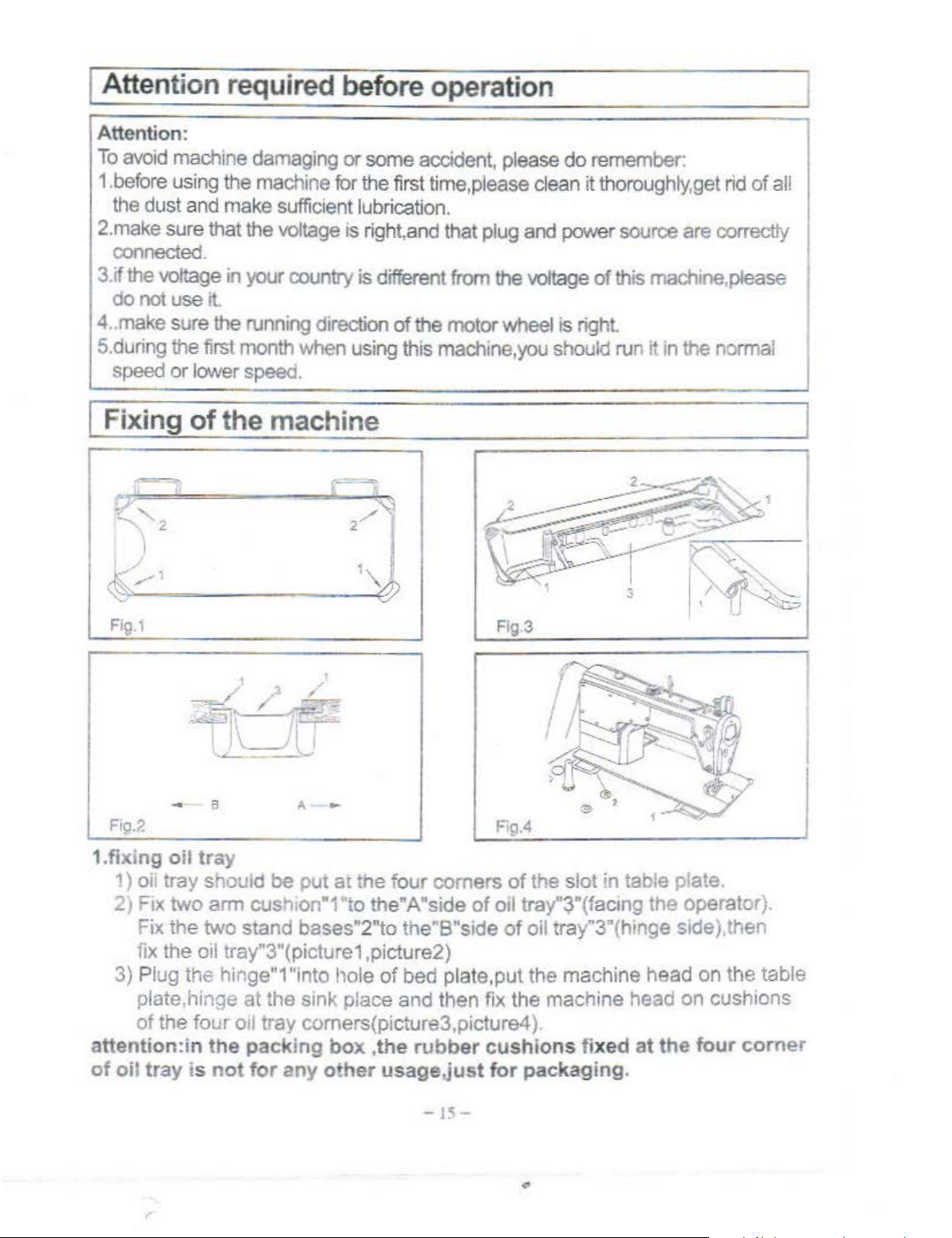
1.fixing
1)
2)
3) Plug the hinge"1 "into hole
attention:in
of
oil
-
oil
tray
oil tray should be
Ftx
two arm cus
Fix
the two stand bases"2"to the"B"side
fi
x the oil tray"3"(picture1,picture2)
plate,hinge
of the four
tray
is
at
oil tray comers(picture3,picture4
the
packing
not
for
put
h1on"1
the sink place and then fix the machine head
any
,~
\
~
2/
1
~
at the four comers
'to the"A"side
of
bed
box ,the
other
rubber
usage.just
of
plate,put the machine head
F!g.4
of
the slot in table plate.
oil tray"3"(factng the operator).
of
oil tray"3"(hinge side),then
on
the table
on
cushions
).
cushions fixed at
for
packaging.
the
four
comer
-
IS-
Page 6
j
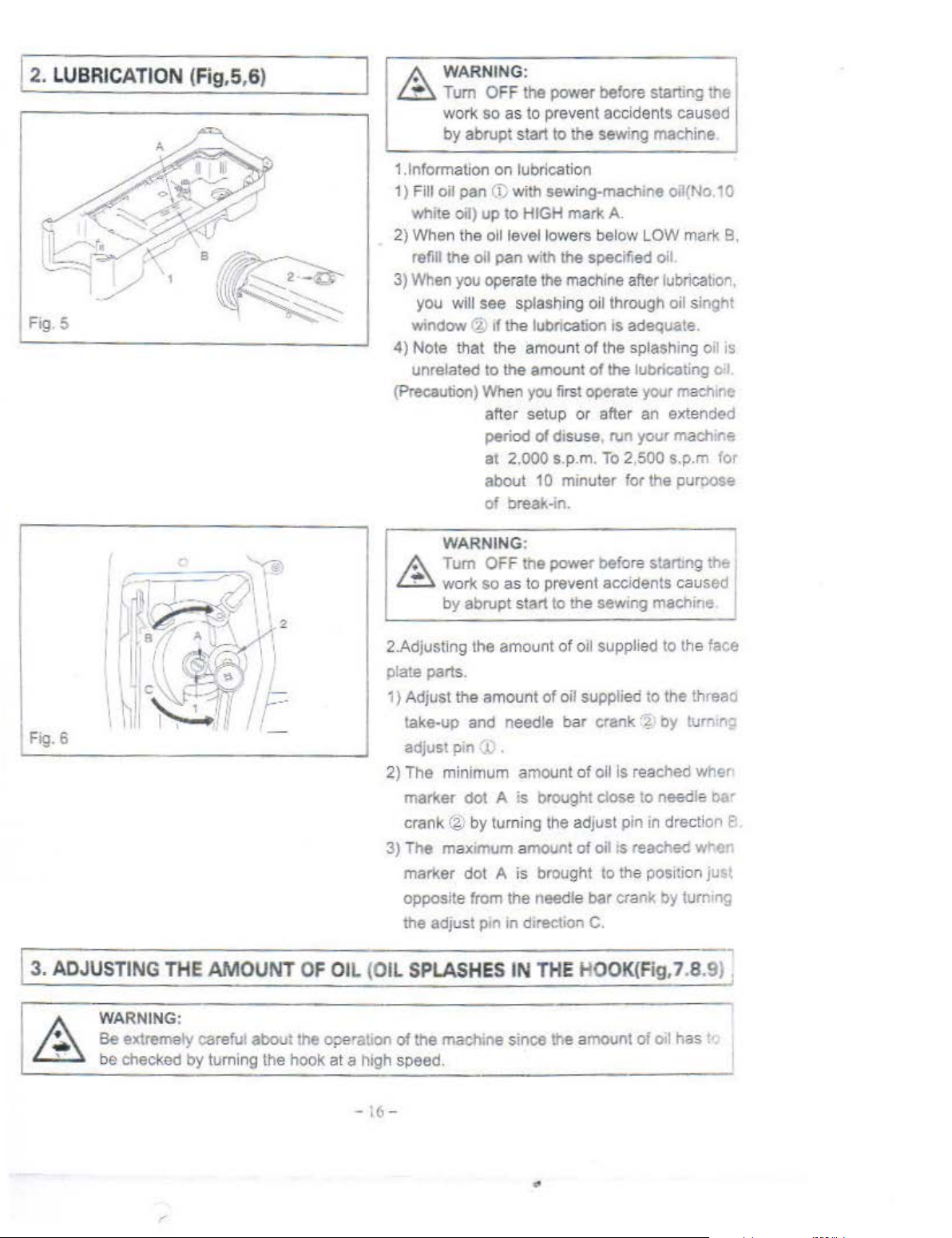
2.
LUBRICATION (Fig
Fig.5
,5,6)
A
WARN
L.t:::l.
Turn O
work
by
1.1nf
orm
1)
Fill oil pan (i:; with sewing-machine oii(No
whit
e Oil)
2) When the oil level lowers below L
refill the oil pan with the
3)
When you operate the mach
you
window(~
4)
Note
unrelated to the amount
(Precaution) When you first operate your ma
ING:
FF
the
power
befo
re starting the
so
as
to prevent accidents csused
abrupt
ation on lubrication
will
that
start
to
the
sew
ing
machine
up
to
HIGH mark
see splashing oil through oil singht
rf
the
lubncation
the
amount
after setup
period
at
about 10 minuter for the purpose
of
of disuse
2.000 s.p.m. To 2,500 s.p.m
break-in.
A.
OW
spec
ifi
ed
oil
me
after fubrica!to
rs
adequate.
of
the splashing oil is
of the lubricating o I
or
after an
run
ext
your
mark B,
machtr.e
10
n,
ch1ne
ended
for
Fig. 6
1
3.
ADJUSTING
THE
AMOUNT OF
2.Adjusting
plate parts.
1)
2)
3) The max tmum amount
OIL (OIL
WARNING
A
Tum
L.t:::l.
work
by abrupt
the
Adjust
take-up and needle
adjust pin J.; .
The
marker
crank @ by turning the adjus
marker
opposite from
the adjust ptn
the
minimum
dot
dot A is
SPLASHES
:
OFF
the
pow
er before stanmg
so
as
to prevent
start to the sewing machine
amount
amount
A is brought close
the
tn
of
oil supplied
of oil
supp
b
sr
amount
dtrection C.
IN
of oil is reached wher·
of
brought to
needle
THE HOOK(Fig
accidents
to
lied to the threao
crank'?
oil;s
bar
to
t p
in
in drection e
reacred
the
posttion
crank
by
needle
by
,7.8
the
caus
ed I
the face
turn:!"<;
b"'
vmer
jus~
turntng
.91;
WARNING :
Be extremely carefut
be checked by turning the
about
hook
the operation
at
a high spee d.
-16
of
the
mach~ne
s
ince
the amount
-
..
of
oil h
as
Page 7
(!)
Amount
of
oil (oil splashes) confirmation paper (?)Position
to
ccnfirm the amount
of
oll(oil splashes)
~[I
·f-L
---
• U$0
.:.ny
papG-r
Fig. 7
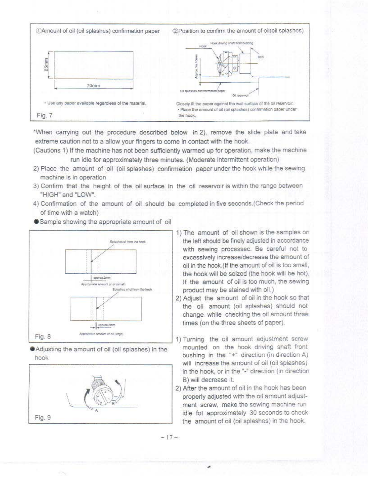
*When carrying out the procedure described below in 2), remove the slide plate and take
extreme caution not to a allow your fingers to come in contact with the hook.
(Cautions 1)
2) Place the amount
machine is in operation
3) Confirm that the height
"HIGH" and "LOW".
4)
Confirmation
of
time with a watch)
• Sample showing the appropriate amount
r-
----
-
70mm
availatt.e
If
the machine has not been sufficiently warmed
run idle for approximately three minutes. (Moderate intermittent operation)
of
the amount
------
.-.!i~"fll
1 :
- I
-~
regardleu
of
["
l
li:ccw:b'.m
....
.....,.,.
r(J
;'«""
of the msterisl.
up
for operation, make the machine
oil (oil splashes) confirmation paper under the hook while the sewing
of
the oil surface
of
oil should
-----
~u'"-'mtmm,.
ol ~ ..... ,.,
S~$(ll~l
,.,,.
...
~~llooll
l'll:d!
of
in
the oil reservoir
be
completed in five seconds.(Check the period
oil
--,
1) The
2) Adjust the amount
amouflt
the left should be
with sewing processec. Be careful not to
excessively increase/decrease the amou
oil in the hook .(
the hook will be seized (the hook will
If
the amount of oil is
product may be stained with oil.)
the oil amount (oil splashes) should not
change while checking the oil amount three
lim
es (on the three sheets
is
within the range between
of
oil shown is the samples on
fine
ly adjust
lf
the amount
of
ed
of
oil is too small,
too
much, the sewing
oil in the hook so that
of
paper).
in accordance
be
nt
of
hot).
'-F_i_g_. _a
e Adjusting the amount
____
hook bushing in the
Fig. 9
...,.,
_~_
....
_~_-_"_"_'
of
____ '
oil (oil splashes) in
_____
__J
t'le
1)
Turning the o
mounted on the hook dnvlng shaft front
will increase the amount
in the hook,
B) will decrease i
2)
After the amount
properly adjusted with the oil amount adjustment screw, make the sewing machine run
Idle
lot
the amount
or
approximately 30 seconds to check
of
il
in the •-• dir
oil {oil splashes) in the hook.
-17-
amount adjustment screw
"+"
direction (in direction
of
oil (oil splashes)
ec.t
ion (in direction
t.
of
oil in the hook has been
A)
Page 8
14.
ATTACHING
THE
NEEDLE (Fig
- o
C- '
.10) I
·f
s -
•
'
' - A
•
v
WARNIN
G:
A Tum OFF the power before starting the
l..:tf::.
wor1<
so
as
to prevent accodents caused
by
abrupt start to the sewing machine.
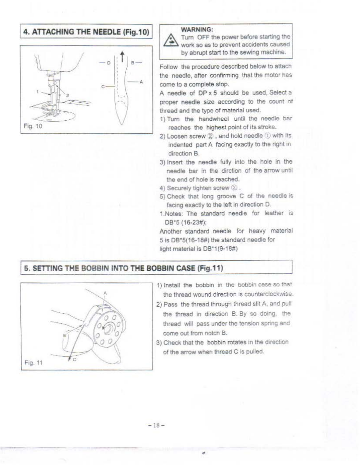
Follow
the needle, after confirming that the motor has
come to a complete stop.
A needle
proper needle
thread
1)
2)
3)
4)
5)
1.Notes: The standard needle for leather is
Another standard needle for heavy material
5 is
light
the procedure described below to attach
of
OP
x 5 should be used, Select a
s•ze according to the count
and
the
type
of
material used
Tum the handwheel until the needle
reaches the highest poi
Loosen screw
indented part
direction B.
Insert t
needle
the end
Secureiy tighten screw
Check that long groove C
facong
oB·s
he
bar
of
exactly to the left in direction 0
{16·23#);
oa•S(16-18#) the standard needle for
material Is
(%)
, and hold needle
A facing exactly to the right
needle fully into the hole in the
in
the dirction
hole Is reached.
oa•1
(9-18#)
nt
of
~:
.
its
stroke.
'!
• with its
of
the arrow until
of
the needle
of
bar
in
oS
Is.
SETTING
Fog
11
THE
BOBBIN INTO
THE
BOBBIN
1) Install the bobbin in the bobbin cese
" '
2) Pass the thread through thread slit A, and pull
3)
-18-
CASE
the thread wound direction is counterclockwise.
the thread
thread
come out from notch B.
Check that the bobbin rotates
of
the arrow when thread C
(Fig, 11
in
will pass under the
)
direction B. By
so
tens1on
in
the d•rection
os
pulled.
so
that
doing. the
spnng and
Page 9
I
s.
THREAD
ING
THE
MACHINE H
EAD(Fig.12
)
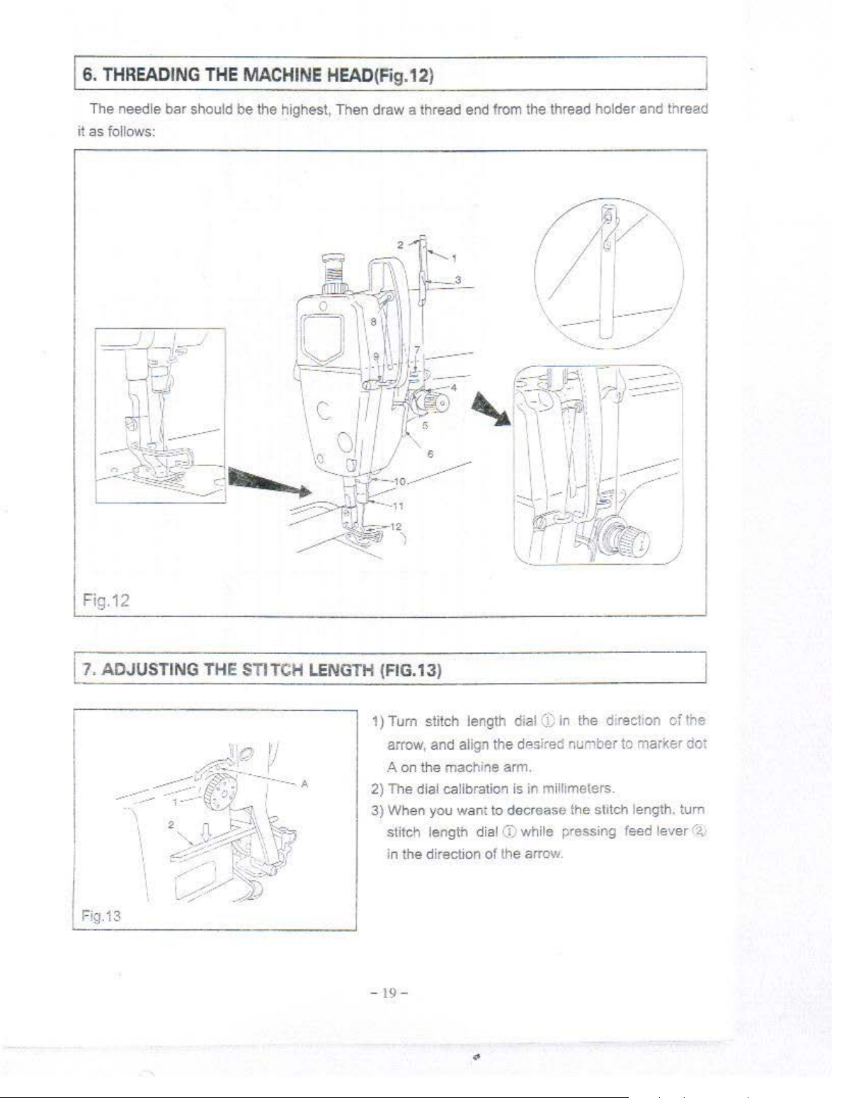
The needle bar should
it as follows:
be
the highest, Then draw a thread end fr
om
the thread holder and thread
Fig.12
1
1.
ADJ
Fig.13
USTING THE STITCH LENGTH (FIG.13)
1)
Tum
stitc h length dial
arrow,
and
A on the machine arm.
2) The dial calibration is in millimeters.
3) When you wam to decrease the stitch length. tum
stitch length dial
In the direction
-19-
(i;
align the desired
CC
while pressing feed lever
of
the arrow.
in
the d:rect,on
nunber
of
the
to marker dot
(2J
Page 10
Is.
THREAD
TENSION
(Fig.14)
Fig.14
,
9.
THREAD
TAKE-UP SPRING (Fig.15)
~~~l\ ,'
~
I
...>-..:::!}) ~ / r
.,.
~--
/'~
~~
~~·
-
f-
~¢.
~~~-!t,}.l
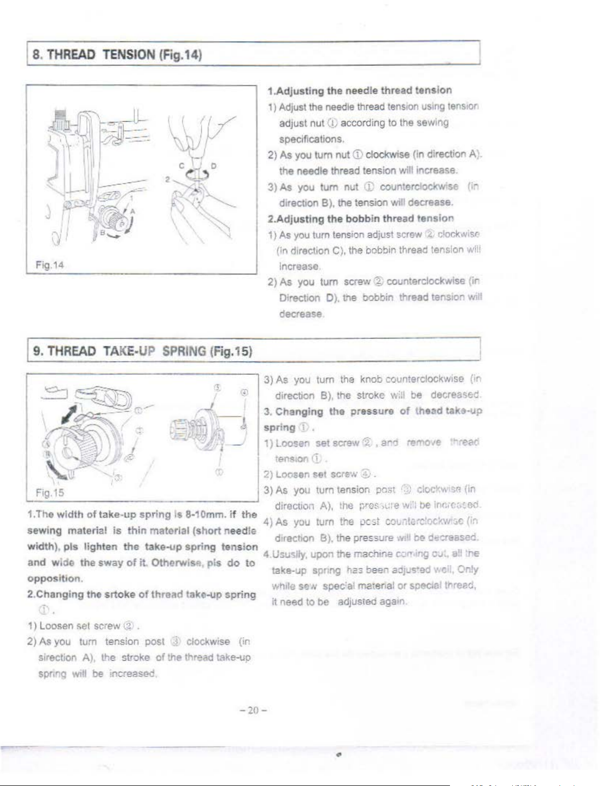
1.Adjustlng
1) Adjust the needle thread
adjust
specifications.
2)
As
you
the needle thread t
3)
As
you
directiOn
2.Adj
ustlng
1)
As
you tum
(in direction C), the bobbin thread tension will
increase
2)
As
you
Direction
decrease
3)
As
you
directoon B), the stroke will be decrease1
_J
l,--,
~~~~
-
~
3.
Cha
nging
sp
ring
1)
~::::
the
needle
nut
(!)
according to the sewing
tum
nut
tum
nut
B). the tension will decrease.
the
bobb
tens1on
tum
screw@
D)
. tne bobbin thread tension
tum
the knob counterclockwise (
the
pressure
'
~
~~screw
thread
<D
clockwise (in direction A).
ens
ion will increase.
J;
countorclockwse (ir
in
thread
adjust screw
<2
•
aro
tension
tens1on
counterclockwise (ir.
tension
of
thaad
remove
using
·.
c'ockwosc
iens1or
take-up
vli
ll
ir
''"r
e~
c
-- .
· J
'.
_Fig
.
IS
Tl
1
.
sewmg
wt • p s
an
opposltoon.
2
.Ch
1)
2) As you
I f k
1e w dth o ta e-up
. .
materoat
'dth)
d
WI
anging
')'•
Loosen
sirection A),
spr.ng
1 1
·d h
e t e
$&1
tum
Wlll
.
19
the
screw
be
",'
J
spring
is
h h . d•rection B). the pressu. re
thin
te
n t e
.
sway
the stroke
1
o 1t.
srtoke
tension post ~ clockwise (in
of
(i
..
mcreased.
Is 8·1
material
take-
up
Ot 4.Ususlly. u
herwis"
thread
of
the thread take-up
,...,
Omm.
if
the
(short
sprtng tension
take-up
pis
need
le
do
to
spring
-20-
2)
Loosen
3)As
1
direction A), the
4)
As
take-up spr.
while seN
il
need to be adjusted
set
you turn tension
you turn the pest
po
spec
screw
:1
J .
pco~t
ves·,c:
co~ n
n the machme c;.,..-•
ng
t.::s
beer
'al matenal or
aga1n
..
·;,; clocl'v.
:e w; 1 be
t.:rc:
w~l
oe
.n
ao;us·ed v.cil, Only
specoa
.
~~(in
ln
<"•C::,~
en
oc:-:w•:.
g
c
(in
d~o:reased.
c;.~t.
a
!! •re
l tnreed,
Page 11
I 10.
Fig.16
HAND
LIFTER (Fig
. 1 6)
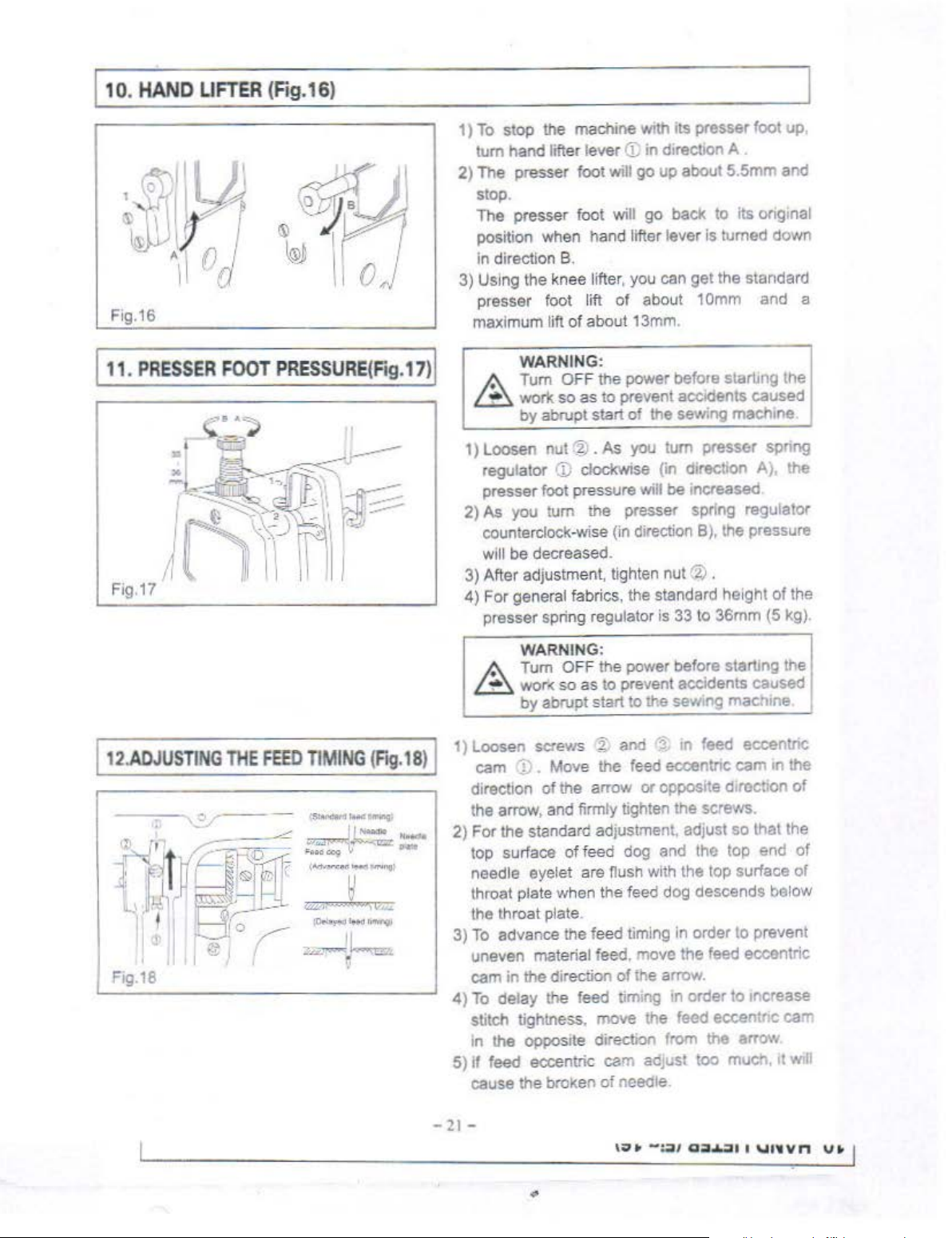
1)
To
stop
the
machine with its presser foot up.
tum
hand
lifter lever
2)
The
presser foot will
stop.
The presser foot
position when hand lifter lever
in
direction B.
3)
Using the knee lifter, you can
presser foot lift
lift
maximum
of
<B
in
go
will
go
of
about 1
about13mm
direction A
up about
back
to
is
turned down
get
the standard
Omm
.
5.5mm
and
its onginal
and
a
I 1 1.
PRESSER
I
12
.ADJUST
FOOT
ING THE
PRESSURE(Fig
FEE
D T
IMI
NG
(Fig.
. 1 7) I
18)
I
WARNING:
A
Tum
OFF the power before starling the
L.:f:'::l.
work
so
as
to
prevent
by
abrupt start
1)
loosen
regulator
presser foot pressure
2)
As you
counterclock-wise (in direction
Will
3) After adjustment, tighten
4)
For general fabrics, the standard height
presser spring regulator
nut
'?.)
())
tum
be
decreased.
WARNING:
of
•
As
clockwise (in direction
the presser spring regulator
arodents
the sewing machine
you
tum
presser spnng
will be increased
8),
the pressure
nut
~
.
is
33 to 36mm (5 kg).
caused
A),
A Tum OFF the power before startmg the
L.:f:'::l.
wor~
so
as
to
prevent accidents caused
by
abrupt start
loosen
1)
cam
direction
the arrow, and firmly tighten the screws.
2) For
top surface
needle eyelet are nush with the top surface or
throat pla te when the feed dog descends below
the throat plate
3)
To
uneven material feed. move the feed eccentric
cam
4)
To
stitch tightness,
in
5)
if
cause the broKen
screws % and
:]'
. Move the feed eccentnc
of
the arrow or opposite d,roction
the standard adjustment, adjust
of
advance the feed timing in order to prevent
in
the direction
delay the feed timing in order
the
opposite direction from
feed eccentric earn
to
the sew,ng maeh,ne.
'i
1n
feed eccentnc
cam
so
that the
feed dog and the top end
of
the arrow.
to
mcrease
move
the feed eccentnc cam
the
of
needle.
adJUSt
too much.
arrow
of
in
11
the
the
the
of
of
will
-
2t-
\
;:> • -:;,
,
a:~
...
.,,
1
'·
"~
v n
V > I
Page 12
113.
HEIGHT
Fig.
19
114.
NEEDLE-TO·HOOK
OF
THE FEED
DOG(FIG.19
RELATIONSHIP
/
(
Fig.20
) I
6
~
1)
2) To adjust
(Caution)
insufficient, the
a, Feed dog b. Needle plate
3). T
)1
CAUTION :
Be careful not to move the feed eccantne
cam too far. or else needle breakage
result
WARNING:
Turn
OFF the
work
'
The feed
out
from the throat plate surface 1.15mm
1
25mm.
·:r
Loosen screw ®
1J
Move
adjustment.
::p
Securely tighten
he
must be adjusted 1.15-1.25
needle
material
n
eedle
suitable height
so
by
abrupt start
dog
the
the feed
If
feed dog for lea ther
plate. The feed
must
plate. while
power before starting t
as to
prevent accidents caused
of the sewing machine.
is
factory-adjusted so that it
height
the
forked
be
is
0.
of
the
feed dog:
of
crank 1 .
bar
up
screw ~ .
clamping
portion
dog
0.~.9
7 -{).8mm.
mm
sew
thin matenal.
of
down
pressure
will
heavy
mm
higher
for
higher
mat
he
just
to
to
make
is
wear
out.
material
than
mld·heavy
than
the
_j
\ G
7
I
-~n
(--(£iii!~
~
~
!Jf-~
[rp
>-
" id.J
I I
Fig.20
WARNING:
&
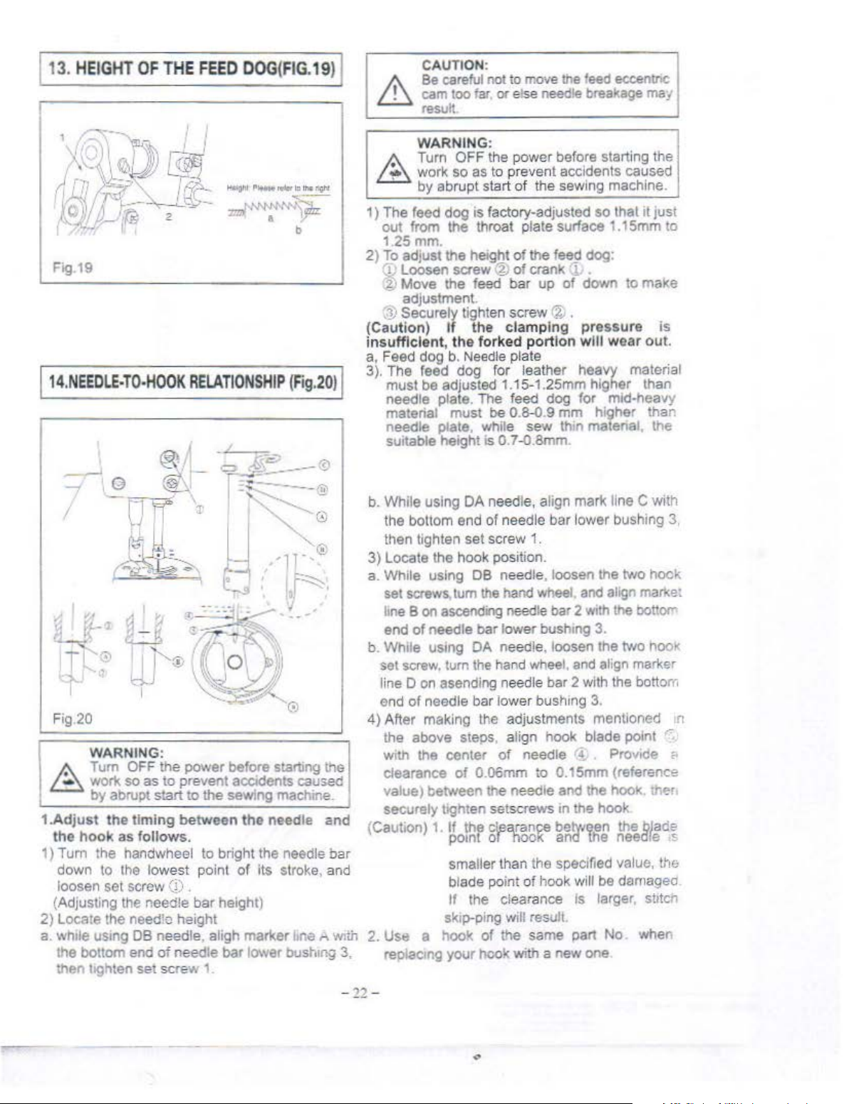
1.Adjust the ti
1)
2) Locate the needle height
a.
Tum
work
by
abrupt
the hook
Turn
the
down
to
loosen
(Adjusting the needle bar height)
wh1le
the bottom end
then
set
usmg DB needle, aligh marker .ne "
lighten
~-
~
-~:=?----0
· . :
\
~-
~
~
~
1
h
OFF the
so
as
to
start
ming
as
follows.
handwheel to bright the needle
the lowest
screw (j) .
of
needle
set
scre
M
' t
-..;;, '
~ik~----··
1\)~:
~
-
"'""
-~~
power
prevent accidents caused
between the
before starting the
to
the
sewing machine.
point of Its stroke, and
bar
w 1.
:r
---
,
~
.·jl>
'
[f~
,
I_
·
~
'®
needle
lower
bust.mg 3,
-'"'
;
·-
,'
and
bar
Wlth
b.
While
using
DA
needle, align mark li
the bottom e
then tighten
3)
locate
a.
While
screws,lum
set
hne B on ascend"'9 needle bar 2
end
of
b.
While
sel screw,
line D on asending needle bar 2 with the boll
end
of
4) After making the adjustments mentioned
the above steps, align hook blade point
with
the center
clearance
value) between
securely
(C
aut
ion)
2.
Use a hook
reo1acmg
nd
of
needle bar l
set
screw 1.
the hook position.
using
needle
usmg OA needle,
needle bar lower bush•ng
DB
needle
the
bar
turn the hand wheel. and align marker
of
of
O.!l6mm
the
light
en setscrews m
1.
if
the
c~
pomt or nooK and
smaller than the specified value,
blade point
If
the clearance
sk1p-ping will result.
of
the same part No. when
yo<Jr
hook with a
, loosen
hand wheel. and align marke:
low
er bush1ng 3.
loos
needle
needle and the hook. tr;er.
arance
of hook will be damaged
r!
to
0.15mm (reference
the
between
new
ower
the
Wtth
en the
3.
hook
the
is
larger,
one
ne
C with
bushmg 3,
two
hook
the botiOffi
two
hook
Provide
the
blade
needle
s!Jtcn
om
'"
r-
<·
.s
the
-12-
Page 13
l
1s.
ADJUSTING
THE
HEIGHT
OF
THE
PRESSER
FOOT
WA
RNING:
(Fig.21
)
A Tum OFF the power before starting the
t..:Z:::.
worl<
so
as to prevent accidents caused
·
by
abrupt start
of
the sewing machine.
Fig.2
1
11
6.
ADJUSTING
THE
THREAD
TAKE-UP
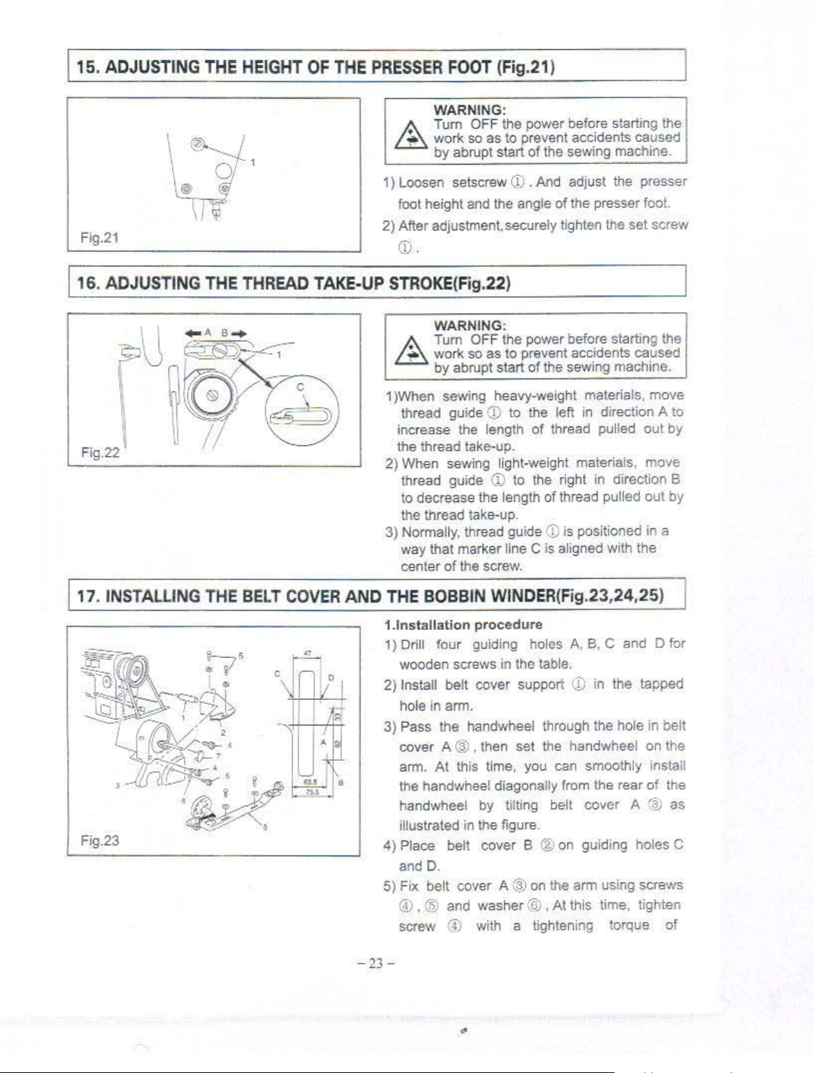
1) Loosen setscrew
foot height and the angle
2) After adjustment, securely tighten the set screw
(j),
STROKE
(Fig.22)
WARNING:
(j) . And adjust
of
the presser foot.
the
presser
A Tum OFF the power before starting the
/..:!::::;.
worl<
so
as
to prevent accidents caused
·
by
abrupt start
1 )When sewing heavy-weight materials, move
thread guide
increase the length
the thread take-up.
2) When sewing light-weight materials, move
thread guide
to decrease the length
the thread take-up.
3)
Normally, thread gui
way that marker line
center
of
CD
the screw.
of
the sewing machine.
to the left in directi
of
thread pulled out
(1)
to the right in direction B
of
thread pulled out
de
(j)
is positioned in a
C is aligned with the
on
A to
by
by
!
11
.
INSTALLING
Fig.23
THE
BELT COVER
AND
THE
1.1nstallation
1)
Drill four guiding holes
wooden screws
2)
Install belt cover support
hole in arm.
3}
Pass the handwheel through the hole
cover A @ , then set the handwheel on the
arm.
the handwheel diagonally from the rear
han
illustrated in the figure.
4)
Place belt cover B ® on guiding holes C
and D.
5) Fix belt cover
@ , @ and washer @ ,
screw
-23-
BOBBIN
At
dw
heel by tilti
(,4)
WINDER(Fig.23
procedure
in
the table.
this time, you can smoothly install
ng
belt cover A
A @ on the arm using screws
At
with a tightening torque
,24,25)
A,
B, C and D for
<.])
in the tapped
this time, tighten
in beft
of
the
(~
as
of
"
Page 14

Flg.24
Fig.25
l
1s
.
ADJUSTING
THE
HEIGHT
OF
of
30
kgf/cm and screw ® with a tightening
torque
screws, the securing state
not
6) F
7) Move belt cov
8)
War
THE
KNEE LIFTER (Fig.26
of
change.
it
cat (f) to the belt cove A .
rubber secticn of
ac
cont
move the
by
0.5 to 1 mm.
in position using wooden screw
Fix bobbin winder ® 1n
and
B using wooden screws
nings
25
kgl/cm.
t with belt cover A (
belt cover 8 in the same direction
: 1) F
2) The
If
you tighten further these
of
the belt cover
er
B @ backward E until the
belt cover B @ comes in
3)
• Then, further
Now
,
fix
the belt cover 8
and
gu1d1ng
or salty
should be installed
bobbin winder should be para
to the plate belt holes.
's needs, belt cover
left and right parts
and
holes A
washers.
,27)
will
washer.
of
the
II
Fig.26
WARNING:
A Turn OFF the power before starting the
t.::::;:,.
work so
by
1)
The standard height
using the knee lifter is 1
2)
You can adjust the presser foot
13mm using knee lifter adjust screw
3)
When you have adjusted the presser foot lift
to over 1
of needle bar@ in its lowest
not hit presser
Fig.27
as to prevent accidents caused
abrupt start of the sewing machine.
of
the presser foot lifted
Omm.
loft
up
i"
•
Omm,
be sure that the bottom
foot@) .
~
~
C
l'e"
-
3----~
I
- - 2
-,..J
r
·~
---<
poslt1on
does
to
end
-
24-
Page 15

119.
SPECIFICATIONS
Application
Max
Sewing
Speed
Max Stit
ch
Length
1-
L•fting
height
of
presser Knee
foot
Hand
lifter
lifter
-
Needle DBX1
Lubrication oil
Moto• oower
1.
11'./hile
Sewing Light materials. the machine need
do
dog and
2. Machine with "R" added
some adjustment.
For Light mediumheavy ma!erials
RPM
5500
Sm
m
6mm(MAX.) 6mm(MAX.)
13mm(MAX.)
9~-18
I
Is
using roller presser foot.
11
For heavy materials
3000
13mm(MAX.)
DPXS
White
to
change the presser foot. needle
RPM
8mm
16H
od
No.10
370'N
- 18
11
For Leather
materials
3000 RPM
Smm
8mm(MAX
13mm(MAX.)
DPXS
20#-23#
bar
.)
·-
and feed
To
order
or
for furt
her
information, please contact:
• Please
when necessary.
•
The
the commodity without notice
do
not
hesitate to contact
description covered
in
our
dis:ributors
th1s
mstruction manual
or
agents in your areas for further
1S
subject to change for Improvement
1nforma~on
of
-
25-
.,
Page 16

~
14:
-=¥
mt
PART
It was a new-revised endition in December, 2001.
The machme with 'A" added
Please conftrm the relative applications Ref. No, part no
S
BOOK
is
ustng roller presser foot.
When buying the parts.
-26
-
Page 17

§
CONTENTS
1,
fJl~~ffi#
2,
.:%:$!1lliU~k~ff~ffii*
3.
~tff.
Machine
YUtl!&&t~~iJJ$!1l~ffi#
Frame
Main
& Miscellaneous Cover Components ...............
Shaft & Thread Take-up Lever Components
Needle Bar, Upright Shaft & Hook
~
........
28
31
Drivmg
4,
U~ffi#
5,
~*4~tffif*
6,
)iillf~ffi#
7,
illi&~ffif*
8, It:;g:,.,
Stand Components ......................................................................... .45
9,
~~R~~M~ffl1*Modei'R"
10,
ll#i*
Shaft Components .............................................. , ...................
Presser Foot Components ................................................... 36
Feed
Oil Lubrication Components ................ ,
Oil Reservoir Components
~~~.!:3i:!J~~~ffi#
Accessories .................
Mechanism Components ............................................. 38
.............................
......
....
.......................................
Belt Cover, Bobbin Winder & Thread
Presser Rollar Special Accessory ...............
.....................................
................ ......
33
.41
43
48
50
..
Page 18

Machine fram .
& miscellaneous cover components
e
-28-
..
Page 19

N~::
'j_PAR
l
.!'~:..
__
I
GR5!\1·~
1
GRSX2-~
1
GS15CI-k
4
GRt-~1)
S
GRSX~-R
6 GR5ll4·R I \
., GS31lO·" J
R GR578-X
9
GR571l-R
I 0 GR"i86-&
II
jGR5~7-H
12
GR611-~
GR800·X
11
GR60'-l-
I
14
IGQ200·R
15
GS310-X ;i
1
l(l
GS310
17
•GRt'<l?
18
IGS31
19
:o
IGL:t\7-~
11
'GR6()<).~
2:!
~GWJ
Ci\v:o2.-k
23
GR60S-
241GR.607-8
2S
GS314-X
'h
Ghl~J-8 1 M.,.~i"i
,.
GR60(·-H
28
IGS315-~
'~
GS11'
'0
GX~IIO-&
31
GM161>·H
GMl"
.~2
GS33~-S
3~
GR604-R
34
!GS~I3 R .i.:!J:llJ~li!TllM'
35
G;uR3:
36 'GS:Joo
~7
I~MW4-RI·firt~~mae,hlid~ASM
38
(rVIIoS-)( lU}'(
39
GW I
IIDJ!x
'-S
I
J jJf';.
1
-~
·S
I {jtt\l>
~-R
I
1
84-~
~
1
I ·U·
.,.l<>
l''f•
R : f h \;<calc
·~
-.<
1
90-X
---
H~
fJ''t"Pl•te \SM.
1
Face
1
~.~l!llf'i!\.'RL~\11/8
f.!
...
~,;·,jg~
~JF.'t'~H:'l~/
1{'
t!ii
I?J~#:fl'~
~f;
<-~~.r:·s~H
Pof,
I><
S1d~
.1,:;
i;;l
~'
<i:
Ga,~et
1!.
tfl~''
.,,
ilHLI
'~"l:r
{L~
It
'<eedl~
i:trt
i r
Needle
.fl:tl.
Th'l.-.!·~oe
Hi.!:H~;f;f,'!'
1
tt•fiJ'•J;!JI}!].TSM3116"X2X
-.r::~t!-J!.'\"TS\13,16
Arr.:
t,ff.\l,,Ji-l'JS:\1111~4')!44)
-kit
·::~?f,
f'l·
~t~r:
hl
Tcn<1nn
+.
t'(
IJ,f,>'( T
:kf~J,
Tenswn
·!:..
~1
1./.
Ten~i-m
f'l!fS.
"'.{
Tonsiot.
;.{14,~;
J~t\~n
!'>!:.ft.;,.~-;
lc'l."''<"'"··· _.. •
~c:!
H~JJi.-1
t.=t~r
'HjJ'i
;JiJ!'(JHr:<flr.
!''
Ten>ion
Screw
Toke-up-nring
~.if
t r l
,,
...
4
•.•
tJ _.,,;,,
, ,
~e~!
:-.edlepl~o~
I
•.
o,RJI.lthre"d
lfl
'>~il
Shdopiur~
f"<
V.:
<;>rir•f
iJ
I::'~CRI"TION
pl.ou
ga,kcl
X+l
L:.:
SeT<"
I/8"X4<1 [.>.!
AR.\.1
"'
hicod
AS\1
..
J.~
Ruhbt:r
Rubber
6 X
pl•tc 1
Kuhlx"T
Ruh!Xr
lhr~ad
thread gutde
bnhing
li',re:.v
ru;de·R•th•
l'hrcad
wn-.itlll
""'
~~~
mn
,,pring
~:"ring
•>•·c
Di~c
1
T,·
.ioJ
•'•I
';
(''SM9/64'
rdct<e
o1ale
lib-!"
X.:OL=~.S
X4(lL:6
'·
Ruhber
X~~
of
ild~
plu~
r1ug
plate
Screw
5CI'I:W
9/0:.
1116--1
:Vl~
1
1i6'Xl5
:\/WX28 L:6
1•'t:")!~~
]I/6,''X!O
X.iQ
L=~
:X~O
X28
..
2M.~
9 Sere"
piug
piu~
guoJe
p1n
ron
thrc:.·' "!tc·
mdicallun
l.=(o
)<.'~L~~St·r,"
1.=:6
A.~M
Dis<
,tnr~r
ilol<kr
f'<'•\1
x-~e:
;,.-rew
p1n
Sc:e"· lllf>-
gwd"·l~fl
~crc·v
piu
L=9
S.·rew
plate
L--9
1.=6
L-~
5
l."o
~•
1
~
' I
.,
.•
.r
J
..
..
'Cr
-tr
*
-t.r
*'
-;..-
.
'·
-29-
r
Page 20

~if{tfUI
LJ
If!'}
R
No
-;;.
~
,
.
~
339-8
Q21
196-8
!!-
8-8
-8
-8
r}
8
It-
£1'.
PART};o. DESCRIPTION
.
40
GS
41
GS299-8
42 GR724-8
GS373-8
GQ195-8
44
GQ11
IG
45
GX
46 GKI53-5
GK162
47
GQI96
48 GRI428-8 0
Machin e frame f miscellaneous co
Ma
ffi!
j!i
ii/~
rt~~Jt~1
1
l'il
:itflt
l:fH~J'iJl
'I'
!i
!'!'
j!
~ .
'R
;t!<;
· ~ '.l
lt'!~tGl!eH
#t
f!i~Hi
JJt~
ff~
'l<:1:
fli
11!!"<1
ve
r corr:g?nents
chine frame miscellaneous cover com onents
I
jj:
~
i4
' ; 1
'4
1
~
t)'3/32"X56
B
ed 'crew
Rul
er
~H
Ruler
M
odel
pla
M
odel
plate
odel
plate
P
ole
iJ
PiR
Thread
fjjt~
,J;t~
Rubber
Thread
Safety-indicating
ring
L=L9 Screw3/32"X56 L=L9
STUD
plate
plate
sere"
te
tak
e-up lever
take-up lever
~
plate
cove
cov
er
f«
QTY
2
4
I
2
I
I
I
2
r
1
I
L;,&h•.
med.iurn
ln.llet
*
*
*
* *
*
*
*
i
I
*
J!j.
~
llt.ll'l)
FPr
al~
~a:em.ls
1
*
.
~
.
ilf.l
t
hel'''f
*
*
* * 43
*
ur
1e<e'oct
rrattr-.z.l!
-
*
*
~
*
·
t:
*
* I *
'"f:?
*
* *
I
l
I
I
I
I
I
I
I
I
!
-3
0-
"
Page 21

2.
±
$tk.&m!xff~~Jlf-1:
Main shaft & th
read
ta
ke-up lever
component
~
Q-1~
~·4
27
-31-
..
Page 22

2.
1J1b.&bHi:fH)'g
·;: f}
l1=
.ft.{~
Main shaft & thread take-up lever components
REF
1\o. J
PART
:-lo.
DESCRIPTION
J I OX
~
:t
4 GH212-8
5
6
,
8
9 GS309-8
I 0
I I
12
13
14
15 01'156 -8
16
17
I R GR588·8
I
'I
:!0
~1
22
~3
24
25
26
27 GP147-8
28 1GS:I04-8
29
30
31
31
33
199~8
01{59~:2
05308·8
GRS95-8
I
l!lf,-k/t
-8 IJErx;~
1*-fXli~l.~~t:l51~X28v!05
~1!tHH:Jitl1¥
li!fblH
GH358-8
GH~
I 014-8
GH350'4-R t!tl_.itf'rdl:!
G0~65-8
GH21)8/2
Gl-1352
GH:I3-8
GS307-S
(iH.>4~-8
Gico--s
ORI1>7-~
GR592-8
OS371-8
GTIS9-S
GS~3~-S
G0256-ll
GR65(l·/!
GR5R9-~
GS.l0~-8
007.59-~
GX
198-R
Go:!~!<-8
GS306-S
GRI>3R
GR808-g
GPI5--R
\GZ22q.g
GR590-S
G0261-8
GRS91-8
IGS311-8
Ji~i1.ii
tlE#x:!
!Jl~>.l";f(\t~
-RI
!J~ttrtlliPilim
2-
81li!t\lllll;.ijiij>i'j
t•fl:.f"-
F:r\
I
trftr.b!i'i);tW~tr913lX~&
tiHUII!fli
H•Tiiill'~
!4lfl.III!J9i·<E~~t'Tl/~OX.!OL=6
~{,itffJ0'\',]1
~11fdfltf!j~I~~.!T9/32X28
:i!'f'lill.J::i~
j~
*l!l.J·(:!~
Ji..flfl,;.(.·f~~t:
l~tlili'i~ut:
.~~Ji!11H
i*:!iitHt:tlldl"'-~
r
~i'illc
!
.!:1ll
.U:Iililit.!l-t
HI!
l1~i1h
_!:.tiJ!il1;a
-~<1•!:;
-8
i!A
.ili:f1l~k·~~f.f:W
I
r
l~
l
~ ~
r-
~t.
I
1·
~
Bh
"!liiiJ
..!:f,-;;lh-!itiioli)fll1l:
lfuhi;m
1
'0-U~ii*(~:-ff9/64X40
•
~t~,
tV>f'f
Thread
~'"FH
liP
I-t
Thread
Oil
Thread
mke-up
F
Thread
H
':till
f't
Tiu-tad
1
-t
Thread
1-;
!\~edle
Needle
Needle
:'\eedle bar<nnl
,
"'\C.:.j(~~:9;o-IX;j()l=4_8
Counter
Counterw
Rubberring
Feed
F~d
II-IX40
Matn~h;aft
Oil
~eal
Tnnm
4
il"-
~t-1140"X40
:,J:~iHl'J
f:
f~l
•r;
..
,.(:li~'ifl!i
Hand
Han<h
tr
Sere~
\1am
l,i;~l~
ilii
co!ler
Main
Oil
lntcrmC<!late
&rew
Thru<t
wheel
hcd
shaft
itill!s
Roller
ll!l\0"'-'t" 0 -ring
take-
up
crank
take-up
resistant
ta~e-up
take-up
lake-up
bearing
bar
bar
weight
eight
dnve
eccentric
dnve
eccentric
L=ll
rcarb
Soapriog
L=6
~h:lf't
from
amount
bushing
collec
Th1u~1
coller
felt
Sleeve
crank shaft
Smw
co'cr
bar
bar
lever
lever
crank
crank
rod
End
;crt"
v l6
Screw
Screw
L=
Screw
cam
cam
Screw
u<hlllg
sere,,
bu<hing
adju~ting
nf
oil
amount
l=6
Sere"
shaft
15i~X28vi0S
ASM
ASM
](ft9164X4nt_.:!~
9/32X28
1/.!0X.!O
9/32X28
lf..!X40
1/40'
X40 Le6
pin
adjusting
9164X40
v16
L:o6
L=
L=ll
pin
L-~
! I
l
2
2
1
I
I
2
1
I
J
I
I
I
I
I
I
I
I
I
i
2
A.
..
,
t.:
*lu
~
I*
*
~
*
*
- .n -
..
I
Page 23

3,
lttf,
~ttk.&btd~!l~ttk5ttll.f4
Needle
bar,
uprigbt
shaft & hook
driving
shaft
components
,___
2
I
---8
'
ta-,3
~"
~~
~·
13--{p
15~
~-16
®--13
1.
17
19
24
~
-1
20
___-
21
22
- 33 -
32
Page 24

3.
ltff
.
If,~
fif
REF.
No. PART
I GRS99·8
2
G0266-8
3
GZ~30-8
GZ251·8
4 GR598-8
5 GS311·8
6
GU152-S
7
GR600-8
GR801-8
8
jG0:67-8
G02S9-g
1
9 GS312·8
10 GR601·8
GRS02-8
I
li
GV132-S
GVI~4-1<
1~
C.ClS~-S
13
·as319-s
14
GC156-8
15
GC15S-R
16
GC154-8
I'
GZ234-8
GZ255-8
18
Gl\
GN566-g
19
00272-8
20 GS403-8
c I
G02~1-8
22
c.o2~o-s
23
Gl\137-l<
24 GR636·S
~5
!GS331-8
26
GR631-l!
GR818-R
27
GS328-8
2R
('.0269-8
00291-8
29
G$316-S
GS414-~
30 GR63.J-8
31
GS330-8
!
tir&iH
.!o}
1\o.
n•r
HtT
~r
H
~i>
ft>i+j1;fiH*
It~'·
rrtE£~if:llf~
iTH
\t:ff fllil
rHT-!fh
ir••"Ftdl
I
.:iH!!!Itfi;SX.14~.5
~;
*=HH~
rr•tt'i
liLt- IDDXIl
tJU'
J
-~~N)~
*t1-;~~~fJii4X40L:S
~$3k~
~~i!I
F$ffi<'):{~,
'l$.
~ t:prighr
-~
...
139-8
Hi
·L:
iJl-C:
'~:llllJ.mJ~
!li'ffi '::tl
~~•.?•
'
;;-jllJJii$-l!t'
~!l~
~t~
"F:tsl'
"F!;bf"":!"'tTli/64X40L=4.~
X'-t~t~til
~~2
~~Hi;~{\1t~.!Jf!tT1
FtlllniJ~-#
-·lll!u
T~u.>:tt:
-t"
r-
.-:Jii· . .oa:J.:;.
Tt!il'i
Hllif'ii•l!I~U't:f.1ll/64X-IOL=3.5
i4!
~5ttllff:
Needle bar. upright shaft & hook
DESCRTJ>TIOl'
t:t,
fN~~
l:~
•fi:
NCC\llc
I
Needle
i!
~
~f.t"'
F
!rt
i.'tH~
!)tH~J
f::
f:
~~
iDBX5
f~·1~
-
F1i>J;q4t
~~
l'pright shaft
Bllbbin
Bobbin
l;~U3116X28L--9
;:-
Hook
Hook
ll1l
ThMt
li1
t'q
i!lu-S:;:
-~
..
,.,.,
;r.t~
Cap
Nee
dle bar
upper
bu.~hing
bar
bar
'ieedlc bar
H9/64
Needle
:-;eedle
Needle bar
Need
le bar thr
•*-1
!']•'
t*i
( N
>haft
Uppe
t:png,htsluft
Rc<~r
P~iooning
Posiuomng
i/64X40L=9.S
Frunt
Front
;-y
T •
!'
Thrust
connecting-rod
X40L=6
Slide
black
Needle
~eedleDBXl
N~eDBX5
collar
'>crew
!)crew
~ar
thread
Needle
r
bushtng
hu•hmg
bar
lhread
bar
lower
bushing
bar
lower
bushmg
Sctew 1/SX44L=4.5
thread
guide
ead gui
Gearofmannhaft(big)
Screw
Gearofuprightsi1aft(~mall)
Gearofupnght shaft
Gear
of
hook
bushing
Screw
lower
·
screw
finger
finger
bushing
c:>ilar
Screw
de
J/4X.iQL=8
bu.•hing
Screw
Cr
9164 X 401..=6
guid
e
guid
e
(big)
drivingshafl(small)
3/16X28L=9
111MX40L=4.R
ll/64X40L=9.5
ew
ll/64X401.:3.5
dri,ing shaft
I
1 *
l
1
l
l
g
I
1
l
I
I
I
J
I
1
1
I
1
I
I
2
I
l
I
1
1
1
1
~
I
"'(<
*
*
-·~
...
components
-::
*I~
* tr
I*
*
*
-34
-
..
Page 25

3,
tt
.ff
,
~tM.l~!
'-f-'j
l<t
REF.
I
1\o. l'ART No.
,,
~.,
...
GR133-S
GIU52-~ F ~at
"
G"l
138
~.>
34
GR633-S
,.
_,::-
GS3~<1-X
36
OS-W2
-8
-8
liHi
iJ$ib~tllf!l:
l:i
-
'Ftla
Hook
drh·mg
He>ot;
dri"in~
tli
:lc
Rnhbm
1
llbi:
Fli:~l1lJ.t:
Hl!l
Ill!
'Fll!:'ii~
c3~
Bobbm
c3~
01l
illJ
J::i
I,
S<'"'w
~Clin116X28L=12
N~dle
t;
DF.SCRlPT!ON
•haft
shaft
wick
ba
r,
uprig
ht s
'.~
\
f''
Screw
3116X28L=I2 I
haft & hook
~.$:
IQTY
I
I
I
I
I
I
driving
i11},
'ti'HI
For
Li~t.1
oed:IJ'n-beav\
tiliictiaJ-.
*
1:!
"{:;:
* *
*
shaft
components
l!t~l
•
r(.:!
beb~y
z:urcnU
·
-tr
*
><'
*
I
I
l
~lf-•1
For
IC?·
Ib.~t
m.tterul~
'
*
*
-::r
?
*
I
I
-35-
..
I
I
I
Page 26

4,
Jf
lJI,IJ~tlH'f:
Presser foot components
2
6-------
\
..
• c
/
/
/
/
/
1S
- 36-
Page 27

4,
Ai
iJ1JI*tli.f-f
Pr
esser
foo
t components
.,
T
ft:
RJ:F
~l
PART
I GRnl'l-8
2 GS322-8
3
GR611-~
4
GR620'~-8
s GR6133-8
I
CoR625-8 < Uf
6
7
<iS3:!3-8
R
Gl\1164
GR803t5-R i3
9 GR61S-8
10
GR622-R
12
OS326-8
I.'\
GS3.:!5-H
I-I
GR6~0-8
GR630.8
16
GR62&
17
GR615-S
IR
GW189-8
19
GW185-8
20
GX201-S
21
GR627-8
GR314-S
"
,,
GS3 IS-S
-·'
1-1
GLlf>S-8
25
IGR613-8
26
GW253-8
27 GRiil4·8
(iZ231-8
28
29
GR615-8
30 GS319-S
31
GS320-ll
32
G0:!6b-8
G0:90
33
GS321-S
:!&~
QTY
0.5
cam
lever
link
vertical
rerum
ase
pin
release
bracke
guide
Screw
Sere"
bushing
bushing.
Scre
#;:
ring
rod
opring
spring
pin
'haft
t
I/4X40L=g
Y164X40L=8.5
w
9164
X
401.=
I
~
"<o.
tF-Iil~tli
'Ldt-~lH+.'!\"T
f.tlj!H~
Jiii!P~
1~Giti!IPHPI11•!4
tit:
5-~
;;!li~tr.:!t
!l,il\;x
!li~•1l·llfi:~
71-~H~~tt.:
Jfii:.
r,:·wH:LtL!!i.tr
llf;U:.~~
ti:'±~-lfl!H
1;5fl'J)1iti.'f
-8
~iXJfi'i{·Ot\.::.l
¥tHU~~t
<..Hii:t'Ri'HHi'
f!~tt:).J!H
>'.tt};rn~
1
•t:f'.UI!~~r.l:if
~f:F~
t~!li~i';
~tt~H
iiii!Ifi
m
!.iiH
I
.z
"''"llll~i~
=z.::t:o.·
£:1
f~f{i.141ifill!n'916-:X40L=8.5
H=:i"'~R
-8
lli~:lff;
i fi
f
f.~l
.f-8 ~
}1-
1.1
F!:!r.:li'l
r.gtp;:;~fi
i'iHH
.
.ji;.hf!-~.tr
t:
Presser<pnng
Bi:l*
Pre"cr
'ifJi.:
H
Pr
esser
" •
'T-'RJ!lrJ
·;;ij1jl~~
~
DESClUPTJON
H"nd
lifter I
S<.·rew
0'\'ll>"l
rJ
1'1
'f''i
rr
·I~
f~?ilcnsion
Ten;ion
Tension
Pn:'-.er
l'\ut
J>re,...:r
rre~ser
Pn:Nr
Pn:•~r
t19/64 X40L=I
Rubber ring
Jl'
f I
Hand
lifter
Hand
lifter link 1
Snap
nn~
Link
<haft
Presserfoot
Prc':-cr
IICI
l.ilii
ng
n
-1"1'!1
Lifton~
Connecting
Ltfung
Tcn'lon rele
,
~pnng
bar
Prc''~r
I/40X40L=8
AS~
foot
ASM
Snap
nng
lever
Lifting
Hmge
screw
Hinge
<ercw
level
rod
Jc,d
connecting
Snap
ring
release
relca.~
supporting
release
plate
Tension
spnng
regulation
guide
bar I
bar
j:Uide
bar
thre3d
bar
lower
barlo"
cr
0.5
~
..
:h~t!
fullcllt
mtdium·Scary
m.a.t~:"IUis
-{:(
I
l
I
*
*
fnr
* * *
I
2
l
1
3
I
I
I
I
I
I
I
2
1
I
l
I
I
l
I
I
I
I
I
I
I
2
l
I
I
* * *
* *
*
*
* *
*
* *
* *
*
*
*
*
*
* *
*
* * *
* *
*
*
* *
*
* GW203-8
*
* * *
*
*
*
*
*
~·C!;n
nn
oa:cnals:
!'<.·~
F:.ill
~)tro-y
;~t~r
m•:ernl!1
*
k
*
*
*
*
*
*
*
*
*
*
*
* I 1 GR626-8
*
*
* *
*
* *
*
* ,:,
*
* *
*
*
*
*
* *
*
*
I
*
*
*
*
*
* *
*
* *
*
* *
* *
*
*
- 37 -
..
Page 28

5, ~
*
'-
Ht~Jf.flf:
Feed mechanism c
omponents
10
21
69
15
65
14
13
38
~37
61
-
3R-
Page 29

5,
J!*'~1f~JH4
if'.}
14
REF.
'<o.
PART
-¥}
}\o.
Feed mechani sm components
DESCRJPTION
I GH341-8
GH355-8 fl4iHiiit1
2 GX111-8
GX123-8 fiiliHM:
3
GR654-R
GR814-8 i!ifhlll
4
Gm7+8
5
GS3·lH
6 GW 19
7 GX111-8
8 GR652-8
GR
813·8
9 GS34 2-8
10
GH214-8
GH353-8 l!*l.iiiT
11
GX204-8
12
GS333-8
13
GH218-8
14
GR653·8
15 GW192-8
GW204-8
16
GR625·8
17 GH344
GI-1357
IS
GS346-8
GS407-8
19
GRn15-R
10 GS.,li-S
11
GX20~-8
~:
GR63Q·l'
23 GR6-IO-S
~4
GR6-II 2-8
GR~II
:'5
GX:07-X
26
GS~-<
·-
GS3:>3-!\
2&
GX22~-S • ~q
~Q
j GR643-8
30
Gi\.ll6'-8
GM
174-11
31 \l1>.L
32
GRil-l~ j :.t~•il;t:t
GR~
W
~i!t~a~l
ll4i!Hi!H\1i
15Hii!I1T<il
FccdadJu.\lrod
Feed
f%-tl'l
Fttd
1\
ilS
F«d
Feed
Feed
i!f'lilt!Tl!Sfdl'f feed
iHii11viltt
1-
8 .i!fl.l'l!mfr K
~nt'IHC!N
iEt~#liiaitfl!
nll~~fl!
iH'illil>'itH~·J
.iU.
I.iti·
i!HiiiHI'I
iUHHfii'•~H9i64X40L=6
tk!fiHf
.il;~l·ii'J
W!llt.~O'I'Iim
filli!'ifltltJ.\
fiiJJ!f.H>H~
~l!tlii!M!illE
&iliUiil!Jli'liilWt
Screw
Spnng
Pin
Feed
Feed
Connecting
Connecting
Pin
Connecting
Spring
Spring
!PliH41ffl!Piil1114
1r1Jitfi1!1Jiiljlll(lf
!:.1i.:d1il:t1•~!1lH
f)'Ji!JHiH
i~i•\1-
!\!!};r..'JT·
i~tlk..
iiifH"~:J.l~
iiill
l -8
'ifu
::t
f"'!T:-J)(iffi1.._
T J
nh-\.~tT9164X40L.-ii
;;s::
;;,.
f 1
J!
f,
i-~
J!>.
i 1 .
f'.!
1 ......
J"li4X40
_j.:\n
{
Lmlo:(long)
Link
t
l!
.;!JIll
1'!\
..
f
!!~:;!'(
!'$Ll516-1X18L=-Screwl5/64
~61-
~
.,.
VI
>!;.Jill
tiM
~(cd
bar<hafl
>r.r
fiJI
l·~~d
dog
F~te!
do$
t Jl/8
X-14L=6
reed
~ar
f~ed
bar
adJU~I
rod
rcgula10rpin
regulator
regulator
re&ulator
re$ulatorbusbing
dial
dial
Screw
rod
rod
rod
Rubber
Snap
RevCT"<C
Reverse
Screw
Sere"
Snap
L=6
Pin
l'hort)
,:It
r<'Cd
Feed
Ad\1.\ling
RcUtninJ:
AS\1
AS\1
ptn
ring
ring
feed
arm
feed
ann
ring
Scrcw9/64X40L--6
adu.<hng
adw.ong
link
Scrct>W6J
ring
Screw
Screw
9/64X40L=6
ASM
ASM
ASM
ASM
~aft
X28L=7
X40L=6
1/8X44L=6
I I
I I
I
I
I
I
I
I
1
1
I
I
I
I
I
I
1
1
1
1
1
I
1
I
I
I
I
2
2
2
2
I
1
1
1
I
I
2
l
1 I
*
* *
* *
* *
* *
*
*
* *
*
* *
* *
* *
* *
*
* *
*
* *
* *
* *
* *
* *
* *
* *
1:!
u *
*
*
*
*
- 39 -
Page 30

5,
~
W~ffi{4
Feed
machanism components
f'-{t
T·'
H
REF.
PART
No.
33
GR657-8
GR816·8
GZ235-8
34
GX208-8
35
GS333-8
36
GLI42-8
37
GH354-8
OS334-8
39
40 GH217-8
41
GS334-8
GS341-8
42
43
GZ236·8
44 OR589-8 i!f.Hl
45 OSI67
00273
46
47 GS344-8
GSOSI
48 GS336-8
49 OR634
50
OR807-8
51
GSJ42
52
GR658
,,
_,
GH216·8
54
OS340·8
00273-8
55
56
GR5S9·8 til
57 GSI67
GR424-8
58
02237
59
GZ253-8
00275-8
60
61
GR656·8
GS319-8
62
GS319-S
63
64 GZ254-8
GWJ93-8
65
GW205-8
GS40tl-8
66
67 GR817·8
68
GR~05-S
GS347
69
J
'"'
No.
tH'i~~
H~f.\¥l;il:!i&
i!H~I
ifittllllmt~
llllmtrl~f19/64X40L=6
tl.l?fiHl'$!l!ri~lJ9/32X28
ili~
i!fl.!I
\li:fifillllili~l'
tftjfJ
tf1
!tl'fl!ii:ff41h!1:~U
fg.
illf!:1il
-8
iH
i.M·li!
f!:lJiH~~~~n
4l¥!W!~U11164X40
ffr'f~~lllll'li!ll
;:f·~~
:{~fi!i.~U3116X28L=I4
&:
til'l'
ltl:t)(~~illi!l'l~fflli64
l
fl3f4li
lfr'f~kJ"l~~Ul/4X
~.i!:i<i-1\l!O~!lll
-8
lfllillfil.:!!ll
fjljii;'
f¥!Jm
~Jiilsf!t&T
~Ji~f!l&
'i'lm.f4l&-f5E-lli~ul/4X40L=8
ili:H~W~~
il!iiiJt'.i.,l!ll.;\I
l:!'!SJJ~!i'l[
JE14).liJi'H1HilliliHT
:i!Ni.l'J
liiJillfHiltt,l;~!m
~-!it'.i.!i.~n
:t
DESCRIPTION
t&
Feed
spring
hook
Feed spring
I
Feed
rO<:ker
Pin
4d!HJll
Feed
rocker
MJfl
Feed
rocker
f3116X28L=15.S
~
fliljpj
Lifting
;f
~!Hlt~9i.ltf3116X28L=I5.5
jf~
Feed
driving
lij;!i
fiij
Thrust collar
l~~
l!HTI/4X40L=6
~~~iPHl
f1t'.i.
'f1llltil~
iFft
Feed
lfi'l'lm
~llliffi~tr
Feed
bar
driving
Washer
X.IB
ilil
fR
Lifting
!Wl
~h'f
Feed
Thrust collar I
Rubber
Reverse
*'
Hill
Reverse
#illi$!J;g
Bushing
Reverse
.f~fTJ/4X40L=&
Feed
tLP.
NJ~
\l'~~f£lii!
St-rew
hook
shaft
Screw9/64X40L=6
rocker
Screw
shaft
rocker
Screw
Screw
3/16"X28L=7
L=7
Retaining
crank
forlc
X40L=10.5
rocker
40L=6
ring 1
feed
shaft
feed
shaft
feed
controllever
adjusting
Reverse
Reverse
Washer
feed
feed
Screw
Washer
¥>
Nut
Screw3116''
Screw3/16X28L=I5.5
Screwi/4X40L=6
shaft
bushing
II/64"X40L=7 I
Screw
3/16"
ring
Screw
3f!6"X28L=!4
Scrtw
shaft
bushing
Screwi/4"X40L=6
Screw1f4"X40L=R
Screwi/4"X40L=8
shaft
spring
spring
X28L=15.S
X28L=7
I
I/64"X40
L=I0.5
f<i!:
QTY
1
I
1
1
1
1
2
I
I
2
1
I
I
1
1
l
I
I
I
I
I
I
2
~~.
For
meilit::m-he3vy
materials
I
I
I
I
I
I
I
I
I
I
l
I
I
I
I
I
Ligbl
)!j:*'f
for
mmrials
cp~U
~
*
*
*
*
lll.$*1
f(l.:
heavy
lcatt::r
muerials
*
*
*
* *
*
*
*
*
* 38 GH215·8
*
*
* *
*
* *
*
*
*
*
*
*
*
* *
*
*
* *
* *
* *
*
* * *
*
*
*
*
*
*
*
* *
* *
*
*
*
*
* *
*
*
1-r
*
* *
* *
*
*
*
*
*
* *
*
*
*
* *
* *
*
* *
*
* *
*
* *
1r
*
*
*
*
*
*
* *
*
*
*
-40
-
Page 31

6.
lfiJ~5tffi.f-l:
Oil lubrication components
/
8
-
41-
Page 32

6,
llif11HttJl
f-f
Oil lubrication components
J~~
12
·
• J
{'t.
REF.
PART
No.
GR672-8 imw
I
GR673-8
2
3
GR6~9-8
GS351-8
4
GS353-8
s
GS310-8
6
GR678-8
7
8
GR675-8
9
10 GR644-8
GR670-8
II
GR671-8
12
GS353-8
13
14
GWI95-8
GS352-8
15
GR659119-8
16
17
GR660
18
GS348-8
GR662-8
19
GR663-8
20
GS349-8
21
GR665-8
22
GR664-8
23
24
GR666-8
GWI94-8
25
26
GS350-8
GR667-8
27
GS328-8
28
29
GR668-8
~
No.
Oil
ilil'fi.l'O~FJJ
J·.
i1lJ1Mtll"B'
illl~~t!Z~ft
ilk~H~H'JI5/64X28L=9
@li!Mf1l:l!JilH3116X28L=6
l!:!ll'l!!
lli
1l:
fDii1llirtiH4
IE!
illlft~
iHH1lli1ll~
ii'tW1Jl<i1ll'i;f
\li~f!!:illl~
ffi~~Hl5/64X40L=9.5
l
tiJ~
i!1tiiel1\'ji.
~W
il!l~il!Jil~H
ilil*
tli{4
i~i*"ii:it-1&
-8
iill~
:
i<:~~i!tfTh13X8
im;.JH$
iill.flillt~
ilil*~'~HT
ilil
illl~n
l!:li1ll
tt~N
H:
·Hlll!~i
~H.ll*9iiltTI
fMillti'~~
Oil
iii
ilii
Oil
t
!iiotf
ti:~
Plunger
~t!!!U
ill
.:!?.
sight
window
Rubber
Main
Oil
Oil
felt
Oil
rerum
Holder
Oil
wick
Oil
rube
ffi
~ Tube
Oil
pump
Oil
pump
pump
Oil
pump
Screw
pump
;:l
l.(
Oil
Plunger
spring
Plunger
-E'
Hook
l/64X40
Oil
tube
DESCRIPTION
ring
shaft
oil
rube
pump
support
Screw15/64X28L=9
presser
tube
ASM
holder
Screw15/64X40L--9.5
Spring
Oil
adjusting
ASM
installing b
Scr,ew
impeller
cover 1
pump
impeller
'c-rew
driving
shaft
L=9.5
joint I
~
Scrcw3116X28L=6
lower
screw
ase
M3X8 3
cover 1
oil
tube
Scre
wll/64X40L=9.5 I
'l&:i:
QTY
iiJ,
mediUm·
I
I
1
1
I
I
I
I
I
I
I
1
I
I
I
I
I
I
I
3
I
I
I
I
nea
...
"{::(
*
y
matenal
Uf.l
i
<P~t~
ForLi~
ma1erials
~*'-1-
for
vy
materials
*
*
*
*
*
*
*
*
*
*
*
*
*
*
*
*
*
*
* *
*
"{::(
*
* *
* *
* * *
*
*
*
*
*
*
*
*
*
* *
* *
*
* *
*
*
* *
*
* *
* *
* *
*
*
*
* *
*
*
*
For
e~thct
s
*
*
*
*
*
*
*
*
*
*
*
*
*
1-r
*
*
*
*
*
*
-42-
Page 33

7.
h
btl~ffi~
~--25
Oil reservoir components
~
.__-26
~
- -
----
I
I
I
I
I
I
I
I
I
I
I
I
L _____ _ _
----
18
I
·
I
23
--------'
11
13
I
I
I
I_
---
-----
I
I
I
I
I
I
I
I
--
-- -- --
~
-
43-
Page 34

7,
idJ~Jjo&JHt-
Oil reservoir components
rr:
-1:}
f4
REF.
PART
~0.
1
GR6roi25·8
2 GR681-8
GH344-R
3
•
~
GR682·8
GR683-8
5
GS355-8 tfi!HllffT
6
7
GR684-8
8 GH345-8
9 GWI96-8
10
GR688-8
GR689-8
11
GS358-8
12
13
GLJ70-R
14
GS357·8
•JS356-8
15
GZ238-8
16
17
GR69016·8
18 GR693-8
19
GR691-R
20
GR694·8
GR692-8
21
22
GR695-8
23
GS359-&
24
GR686·B
GR687-8
25
26
Gl::!Xl41-8
-13-
No.
jW,
1>:¥-*'~
t,
DF.SCRIPTIOX
i'1B
fl
ffH1=
Oil
reservoir
iefl:
Oil
re<CTVOIT
tfllli!llffl'
ili!ii
!.ll:!k''iif/1.
llilllitlJfTOJI;fl:
{ltf:Uil~l~ldltli'i
U:tuiiii!Mtll~
tfl:£W$!!!1Fnt5(1.
tflli~lf!i!I.H
l~t\\Wi7!k!IHT9132X20L=20
<.:r.Jill!~!ii!!Hl'li.l11l'!l~15164X28
~l~l.ltli!iRlflij!
IG(oolilbli'it'IH
tfl/EP,'~~7f
~t\HH~I'f
l~t!l..fl;(tk'l~
1\ki!i.
t.iltiA
~tiA
I'Mi'H
115'<l\i!tTI5/64X28L=15
ii!!Atl!l!!ti
jJll~.'!
imfH<it
~
Oil
ff
Hfl!:
~
j)):
PI{
1'1'1
Top
reser.·oir
Head
Screw
Twisting
i\;it.
f>!llifi5164X2S
Screw
CJ
t'llil
Knee
Knee
Knee
pre~smg
Knee
Knee
pressing
Knee
Oil
reservoir
Oil
reservoir
Oil
re.~ervoir
ASM
AS~
pm
ofbftmg
gasket
aa,Jcet
Rubber
Two-way
spnng of
Snap
nng
Brocket
!<nee
pre~siny
pressing
pressing pla
pl
ate
pre~sing
plate
plate
pressing plate
Screwl5/64X28L=15
cu~hion
seat
nail
~
presser
ring
cnmlc
~30
plate
rod
foot
of
lifting
two
way
Screw9132X20L=20
Nut
15164X28
Screwi5/64X28WO
~haft
ASM
te
cover
rubber
holder
presser
crank
~:!ii:
QTY
I
l
l
l
l
4
I
1
foot
I
1
I
I
I
2
2
1
1
l
3
l
1
3
I
1
2
2
4
Focl!"U!
IPO:bcrn
rr~
I
·
~ta")
*
I
*
*
I
* *
*
*
*
I
*
*
* *
* *
*
*
*
*
*
*
*
* *
*
*
* *
* *
*
*
I
*
irHM
~~,~
For
rn!!tr..:.ls
C!ta\Y
-.tr
l
for
~C:J:be:
ll'~ll:~
•
..lt
*
* *
*
....
*
~
~
*
>-1'
*
* *
I
*
lZ
*
~
*
*
*
*
*
*
*
*
*
*
*
* *
* *
*
*
*
*
* *
* *
*
* *
*
*
*
I
-44
-
I
I
I
I
Page 35

8, lti!f.L
, __ l _
~MtR§
3
.!:j
;J:~!(.~1tffi.f-l:
__
,
Be
lt cover,
7
bobbin
winder & thread
stand
comp
onent~
' I 4 I
5 '
10
I
!1!~
IT~~J&
11
'
~
L _ _ _
12
.,df'
__
I I
I
:
:
_ J
I
J
-1
6
0-43
38
49
l
~
/1//?,.
v c.
47~~
L
Jl~~
43
-o
"
\~
~~
4,1
49
36
~
~36r
46~44
~d5
~~
®
0
~
48
31
-45
-
..
Page 36

8,
~~IH'S
If-'}
REF
.
i*
PART
,
~JH
iHEi;:i~~~ijiff:
-17
'-o
.
Belt cover, bo
i\
DESCRIPTIO~
.1/j;
bbin
winder & thread stand
~;:
QTY
jil,
'1'41-1
Fui..tPI
.....t.;.-rbelvy
cwmoh
components
1.'1-n
Fuba-}
.,.._
SiiJ.f1
F
O<
tutm&ls
-Ko.
I 1GKI54-8
'aR698-R
2
3 GKISS/3-8
4
GKISf>-8
GKl57i2-R
5
6
GS
361-R
i G$360-8
GS362-8
8
9 GR699-8
10
GB$204-8
II 084210-8
12
13
GS368-8
14
IGR712-8
15
GWI99-8
16
GLI71-R i::f.
GS365-8
17
18 GR709·8
GR70S-8
19
20
GWI98-8
21
GS364-8
GS366-R
22
23
GS363-8
24
GR819-8
2S
26
GPI48-8
27
GZ239-8
28
GB$204-8 t'itl.
29
GBR210-R
GR713-8
30
31
GZ240-8 ~
32 GZ241-8
3JIGR714
34 GR715
35 GR716-8
36 G$369-8
37 GR717-8 .Uttf!!l
38 G$370-8 tHtH
39
~R71R-8
40 GR719-8
41
Ll72-8
42
GR720-8
r.tl:ifl9
8J¥?.:~:11;"/,f.1
r ~
F,il;J.Jt:iflif't-
J~f~lii:.r!-'ie
f,'i'?-'R.Jilllllt-
Fn~'it
!T:Jjj'l,j';;~LlJ~H
ltt~n
~H!:l:m!
f.i;:i*~~*
-+-*-H
ct~~lffiJ
i..~~~~r&f;l
Wi.}{:t\fli
il~:A!Ut
UUH#.-IiJ:
ioij•JQ.J~Jz~~ITII/
ffi'liJJ!il-~
&ttlH~!ti~lJJ:!f;;
il~fUJU;~~
~t!<
I~G!fflliif!L
i~~~¥iJ!.llfi
tift:Ut~
~
lJJ~jl(;~~rr~~
t)tfl( ~
m~~
t!~!>l!
~
nftl.;~S,-t.:f,m-$.IID
!'t~HT!llltiif'~/t
~H
tlt!lf.!H
f~~H
-8
-8
fl:~i:ttli.ff
t.H!!i
ti1W.U~~~fT
~~tr55\~m
fHH!~~
fl.il!J~tt
~f!
Spool
-
~ Beltcover
Beltcovercap I
Rear
Rear
ttt
Belt
Screw
Washer
P!tT
:!fr~
Washer
1
4
Thread
Thread
Thread
T
Presser
Rubber
Positioning
!",£
Screw
fT
Screw
riH'!'
Bobbin
Bobbin
Bobb
~!ll\
Tii
.1:11
~~
:!~
Thread
Spool
wheel
in
shaft
n
wood
Spoolrest
Spool rest
Spoo
Thread guide
~
Thread
pin 2
Spring
Washer
1\ut 2
res
t 2
Rear
bell
cover
ASM
belt
cover
cover
ASM
cover
suppon
Screw
Screw
tension
1164X40L=7
tenSion
tension
ension
64X40L=5
plate
fT
118 X 44
Wa
winder
screw
Washer
Spool
l
re.~tjoint
guide
Screw
guide
ring
washer
ASM
.8 S=wii/64X40L=7.8 I
()Jsk
spnng I
om
Screwii/64X40
brake
finger
L=
12
Screw l Ill X 44
sher
ASM
rest
rod
cap
lowe
r
rod
upper
rod
ASM
ASM
joint 2
L=S
L=
12
2
2
2
2
2
I
2
I
I
2
2
I
2
I
1
I
I
1
I
I
I
I
I
2
2
1
1
1
I
I
*
*
I
I
I
*
*
*
*
*
*
*
*
* *
*
*
*
* *
* *
*
*
*
*
*
*
*
*
* * *
*
*
* *
*
*
* *
*
* *
*
* *
I
I
*
*
*
*
* *
* *
* *
*
*
*
*
* *
* *
*
*
*
*
*
*
*
* *
* *
*
*
* *
*
*
*
*
*
*
*
*
*
*
*
*
*
*
*
*
* * *
*
*
* *
*
*
* *
*
*
*
*
*
*
*
* * *
*
-{;r
*
*
*
* *
*
I
* *
*
*
I
-
46-
Page 37

8,
.lt'ftf~
J¥-17
RE
F.
No.
43 GR721-8
44
45 GR723-8
46 GLJ73 -8
47 GS401-8
48 GLI34-8
49
,
1
fl:
PART
GR722-R
GR750-8
~!j!il§
-!}
No.
~
;l!.l~ti~D.f1:
"
t~W~tj
+'t•t
tU
Hf
~l*!·
~
lil!lf!T
~it!filll
t
Umi~ll~
l
ie~
IT
IH!I
!t
!ii'ltT
ti.:kJI!
tUt~
Spool
Belt
cover, bobbin
~
DESC
RIPTION
Spool
reuiner 2
f.
~JHill
Nut
Spring
Nut
H
Screw
f.}
Nut
retalller
""'
washer
washer
winde
r &
flfit
QTY
thread
2
I
2
2
2
2
stand
~'
rt'Jinl
f-ori..:~
toealil!l'l-
:nl!eriL~
* * *
*
*
*
*
*
* * *
I
I
component
"~ I ~.tn·
Fcrtn
w
'!ntttna
~
*
*
*
~.
lct~1"<"
~
:m•·
I'
or
ent'i
*
*
'*
* *
*
*
s
I
-47
-
"
Page 38

9,
~~ Rm~tJ.IJ
r-
- -
-----
JW
~
ffl
f4
Special
,
I
I
part
s for model "R" with roller
1-3
pre
sser foot
@-4
18
~
19
~
--
5
- L
2
I
12
-4R-
Page 39

9.
~-~-R
~~Bi
iJill
~
Jllf-1:
Special parts for model "R" with roUer presser foot
!¥~\
ft
REF
.
No.
PART
1 GMI75·8
2
GMI76·8
GW206·8
4
UR820·8
5 GR821·8
6
GR822·8
7
GR823
R
GPI
55·8
10
GRl\24-8
11
GS409·8
12
GS410·8
13
GR825·8
14 GZ256-8
15
GW207·8
16
GR826-8
17
GX
225
IR
G$41 I·R
19
GZ257·8
20
GS412-8
21
GR827·8
·8
-8
..
.,
No.
i,.
Pi
Needle
~
f4
:if
Feed
il.liiJdii
ttiH:U!:J
iM~J
fi1~11i!llll~
lR~lli!llll!tli
ffi:
1M~!ib:g
111~
i«t~t.!J~ili~
~~~~~~~il!trr
H'*ffi
~
~Hi
~·J;l~~
~~~:!JH~m
rntNf.!llll~~~l!!U
IJitf
iiHB
!1ltt~
Presser spring
I:.IWft
~
Roller
SICel
Spring
j:'i m ~ spring
Spring
Prcw
Jt.l!lilffi:lit!ii:I~¥J
Fi
plate
dog
Needle
li't
Roller
Roller
Roller
ball
~rr
seat
Spring
Pin
foot
nger
protector
~
DESCRIPTION
bar
thread
guide
Roller
prc.s
cr
foot
presser
seat
presser
handle
bushing
Screw
Screw
shaft
washer
Screw
Screw
~
ASM
~~~
QTY
l
I
I
1
l
l
l
1
1
48
I
I
I
I
I
I
I
I
I
1
I
.
j!J .
't':t~t
for
Lighl
~
.-.mnzh
17
f:l I ,7;::.N
Fctbca~
"""'"""
* I
*
*
*
*
*
*
* * 3
* *
* *
*
*
* * *
* * * 9 G0292-8
* * *
*
* * *
* *
* * *
* * *
* *
*
* *
*
* *
*
*
*
*
* *
*
* *
* *
Fot
tvo·x:
..-.o!s
*
*
*
1:(
*
*
*
*
-49-
,
I
Page 40

10.
Nff-f
Accessories
5
7
10
~
\
9
)\
-50
-
"
Page 41

10,
/¥-IS'
REF
No.
f#f
i't
PART
tJ:
Accessories
")
No.
,g
DESCRIPTION
~
fL
~
QTY
i1
'
<P
!=i-l-l
ForLglu
rnedlum-l!eavy
mat<!Uis
l'i
'1 I
£~t:~
r
For
beavy
mtleria!:s 1ma1cti11
or
!eadlc:t
J11
I
GR69612-8
2 GR697·8
3 GBXI42-8
4 GVI32·8
s
GR700..8
6 GR701-8
7 GR702·8
Gl'
8
9 GFIOI-8
10
II
12
139·8
GBR211
GR703/
·8
3·8
~
:klilHl.J~i4
!Jl:)l.:ii~t!l~
tll;1d!JiHiJ.@:fT
~
r+
Needles
~~7J
~tt7J
9,!1!££
~·(:
jjl~.ij.
~51.:
1
i!ll1iml!t
ilbfi:f.!ttOil reservou
1};:)
(
7J
(11-)
Bobbin
Head
1:tt
'1')
CO\er
Head
?il
Head
connecting
Head
connecting
Head
conn
ecting
I
bag
Screw
driver
(L)
Screw
driver(M) I
Screw
driver(S)
pole
bottle
:-"ith
Oil
magnet
hook
hook
hook
socket
nail
2
2
4
1-El.
I
I
3
'
I
I
1
I
f:r
*
*
*
* *
*
*
*
* * *
*
* *
* * *
*
*
*
*
*
*
* * *
*
*
*
*
*
I
*
I
--(:(
*
*
.
-51
-
..
 Loading...