

Page 1
Parts
Checker
For
Compact
Single
Head
Eft
Biti
Embroidery
ftit~l)J~
!I
i.E
*11.
•
Machine
itt=
IIIII
Page 2
CONTENTS
CONTENTS
1
@t.ilt!SJ;~·-
Table guard
2
-~--~
Rotary
·3
A!:l86~
Trimming
4
til~-~
Arm
5
ttff!ll~-~
Needle
6
~!:l86tiL..........................................................................
Upper
7
·@.·~
Color
8
ttff•
Needle Case (1)
9
ttff•
Needle Case (2)
10XIDJ!J1~86~(1)
X-Axis
11
XIDJ!Jiiii1.J86tiL(2)
X-Axis Drive
12
Yta.J!IIiii1.JMm.
Y
-Axis
hook base
..........................................................................
..........................................................................
bar
thread
.........................................................................
Change
(1)
(2) . . . . . . . . . . . . . . . . . . . . . . . . . . . . . . . . . . . . . . . . . . . . . . . . . . . . . . . . . . . . . . . . . . . . . . . .
Drive
Drive
13!Je!:IH86tu:
Thread
14!:1.86il'L
Thread
15~~~·!;1···
Bobbin
161@.
Electrical Parts
17EI!JJM
Power
181@.j!fl6tit
Operation
Tension
.....................
Stand
Winder
-t86~
. . . . . . . . . . . . . . . . . . . . . . . . . . . . . . . . . . . . . . . . . . . . . . . . . . . . . . . . . . . . . . . . . . . . . . . . .
......................................................•...................
Supply
...........•........•.............
...........................................................
cover
......................................
part
·············
····.··
·. . . . . . . . . . 1
...............
. . . . . . . . . . . . . . . . . . . . . . . . . . . . . . . . . . . . . . . . . . . . . . . . . . . . . . . . . . . . . . . . . . . . . . . 9
driving
...........................................
parts
hook
System
: . . . . . . . . . . . . . . . . . ... . . . . . . . . .
....................................................................
System
(1)
. . . . . . . . . . . . . . . . . . . . . . . . . . . . . . . . . . . . . . . . . . . . . . . . . . . . . . . . . . . . . . . . . . . .
System
(2)
. . . . . . . • . . • . . . . . . . . . . . • . . . . • . . • • • . • • . • . . • • . . . • • • . • • • . . • . • . . • • • . . . . . • . •
System
. . . . . . . . . . . . . . . . . . . . . . . . . . . . . . . . . . . . . . . . . . . . . . . . . . . . . . . . . . . . . . . . . . . . . . .
Base
·
....................................................
.....................................................................
Box
·. . . . . . • . . . . . . . . . . . . . . . . . . . . . . . . . . . . . . . .
Panel
3
5
7
11
13
15
17
19
21
23
25
27
29
31
33
35
Page 3
I
....------
1.
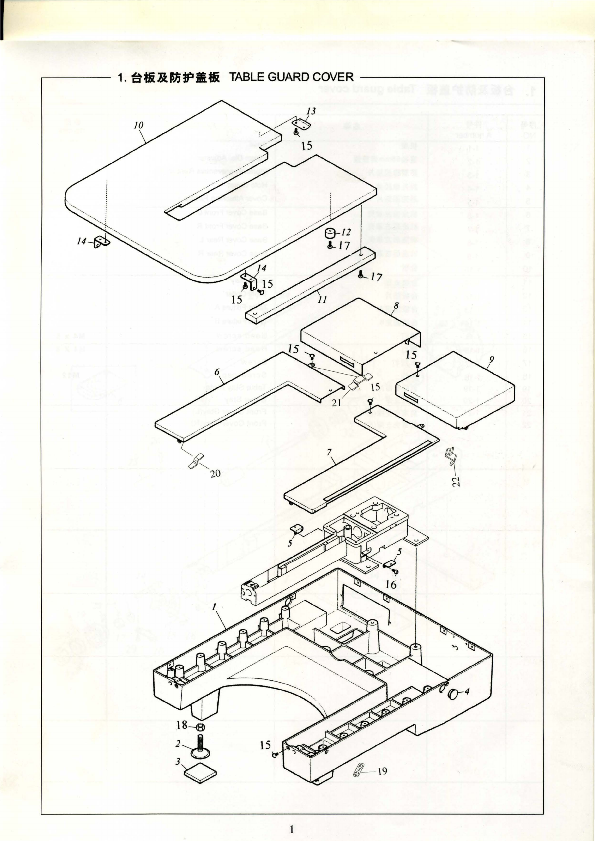
e~R.ISJ;~M~
TABLE GUARD COVER
--------------,
1
Page 4
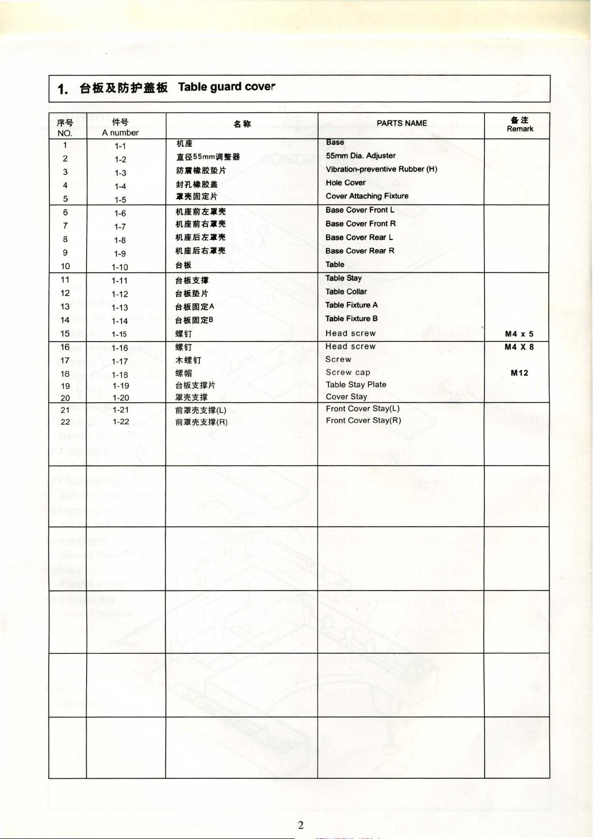
1.
81i
&
ISJ;
tp
llli
Table guard cover
Ff.!iS-
NO.
1
2
3
4
5
6
7
8
9
10
11
12
13
14
15
16
17
18
19
20
21
22
14:-'iS-
A
number
1~1
1-2
1-3
1-4
1-5
1-6
1-7
1-8
1-9
1-10
1-11
1-12
1-13
1-14
1-15
1-16
1-17
1-18
1-19
1-20
1-21
1-22
.s•
mli
.B:f255mmil)§lft
~In•-tt~mit
iHL-tt~•
.a?J~e~:iEJi
*'l/iftr.tt:.a?Jie
*'Lifntr=ii.a~
*JL/i5.tt:.a?Jie
*'Lif5=ii.a~
iH&
~U.&1itt
iH.&Il:Ji
iH.&~:iEA
tH&~:iEB
~fl
~fl
*~fl
!H.U~
~f&1i:~J:!i
~~1i~
Wi"M~1i:~(L)
1WM%1i:~(R)
PARTS NAME
Base
55mm Dia. Adjuster
Vibration-preventive Rubber (H)
Hole Cover
Cover Attaching Fixture
Base Cover Front L
Base Cover Front R
Base Cover Rear L
Base Cover Rear R
Table
Table Stay
Table Collar
Table Fixture A
Table Fixture B
Head
screw
Head
screw
Screw
Screw
Table Stay Plate
cap
Cover Stay
Front Cover Stay(L)
Front Cover Stay(R)
--~
Remark
'
M4
X 5
M4
X 8
M12
2
Page 5
~··
2.
••••m:
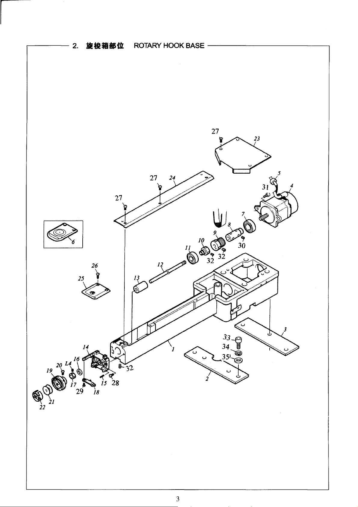
ROTARY
HOOK BASE
26
25
~
~
3
Page 6

Rotary hook base
J¥-ij-
No.
1
2 2-2
3
4 2-4
5
6
7 2-7
8 2-8
9
10
11
12
13 2-13
14 2-14
15 2-15
16 2-16
17
18 2-18
19
20
21
22 2-22
23 2-23
24
25 2-25
26 2-26
27 2-27
28 2-28
29 2-29
30
31
32
33
34
35 2-35
14=-ij-
A
number
2-1
2-3
2-5
2-6
2-9
2-10
2-11
2-12
2-17
2-19
2-20
2-21
2-24
2-30
2-31
2-32
2-33
2-34
451;
*'1..6~
fll.lif';R.A
mlif'x•s
fi.IJJIEI!fll.
I!:IIJ
tU.&
-~
"Ftlll···
"F$$
1l
wu~
-~·A
-~
"F$i
••••
8
ttatx••
··-
:1:~7.
94mm$i.
····~
••x•
••
i!t.IIJ:i!tltl
#tilt\
UtJ!
f}llif'.iii~A
fll.J*.ill~
ttlt
oo
flHit
~d~
n
~~~m~•n
•n
•n
1*17\fA~:i'E•n
•n
1*17\ift~l'E•n
•n
5!jjiffll:J:t
.ifL!ll:J:t
PARTS
NAME
Ann Bed
Bed Stay A
Bed Stay B
Servo Motor
Toroidal Core
Needle Plate for tubular hoop only
Ball Bearing
Lower Shaft Joint
Lower Shaft Pulley
Bearing Collar A
Ball Bearing
Lower Shaft
Rotary Hook Shaft Bushing B
Needle Plate Bracket
Spring Pin
Rotary Hook Shaft Spacer
7.94mm
Rotary Hook Support
Rotary Hook
Rotarv Hook Sat Screw
Bobbin
Bobbin Case
Bed Cover A
Bed Cover
Needle Plate for tubular and cap
Round
Screw
Screw
Screw
Hexagon
Screw
Hexagon
Screw
Spring
washer
Oia.
Collar
countersunk
socket
socket
washer
screw
screw
Remark
-~
Option
3P*12
11/64" X 40
9/64"
X 40
11
/64" X 40
9/64"
X 40
M4
M5 X 20
M5 X 6
M12
4
Page 7
I
r------
3.Jl!i&IH:!L
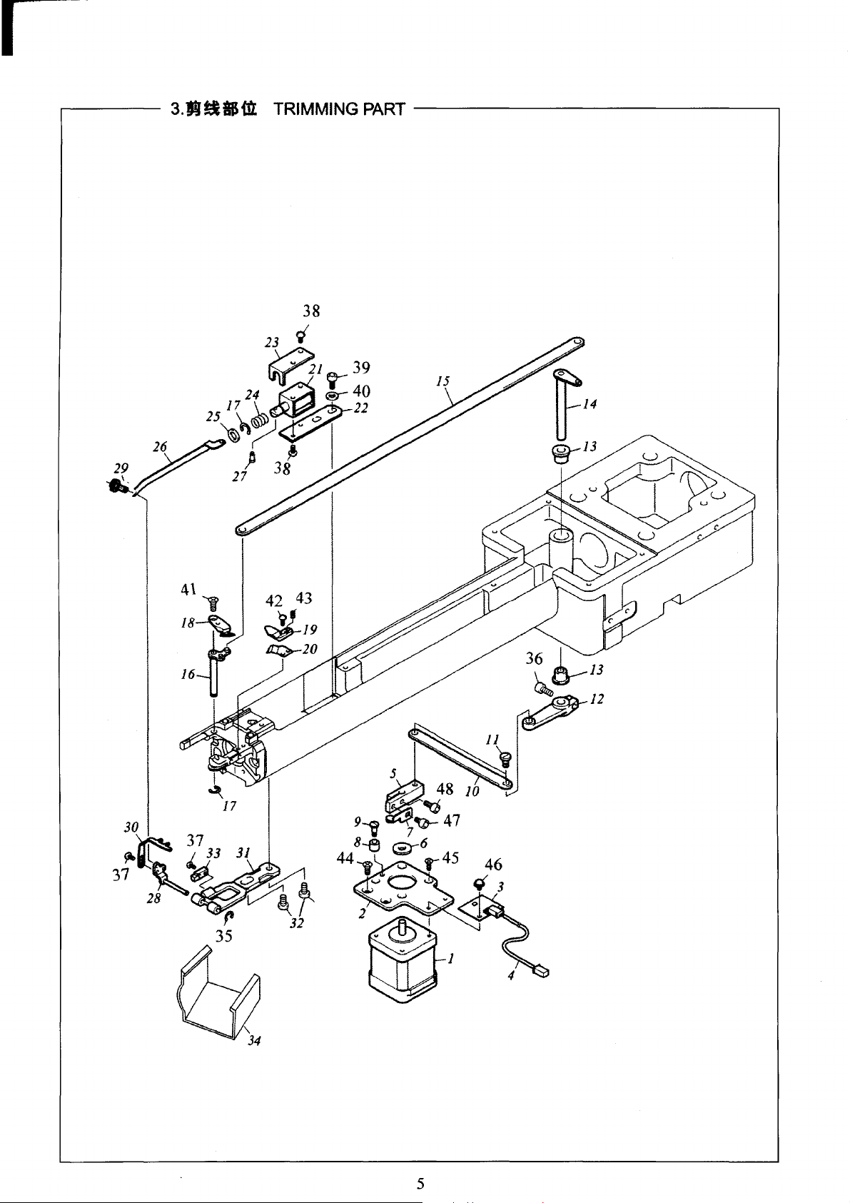
TRIMMING
PART
------------------.
~/4
@j/3
5
Page 8
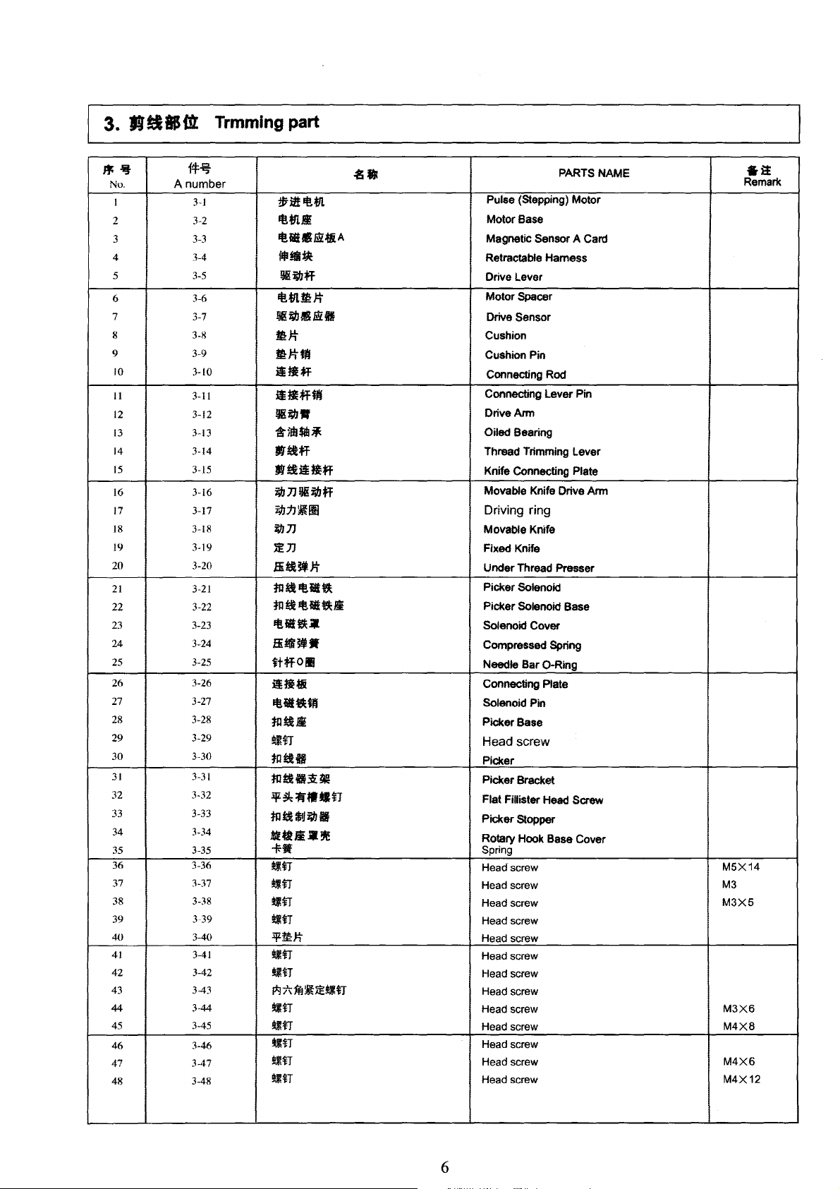
3. R!IIS
m:
Trmming
part
,.~
No.
I
2
3 3-3
4
5
6 3-6
7 3-7
8
9 3-9
lO
11
12
13
14
15
16
17
18
19
20
21
22
23
24 3-24
25
26
27 3-27
28 3-28
29
30
31
32
33 3-33
34 3-34
35 3-35
36 3-36
37 3-37
38
39 3-39
40
41
42
43
44
45 3-45
46
47
48
A number
f!f~
3-1
3-2
3-4
3-5
3-8
3-10
3-11
3-12
3-13
3-14
3-15
3-16
3-17
3-18
3-19
3-20
3-21
3-22
3-23
3-25
3-26
3-29
3-30
3-31
3-32
3-38
3-40
3-41
3-42
3-43
3-44
3-46
3-47
3-48
-881
~l!"-tll.
tt!.tll.Ji
tt!.IUI.IiU&A
flliilftfic
!lii&bff
"-tn.~J:t
Jjgi&IJliSbift
mJ:t
I!J:ttf
i!ti*F
i!tlf"Hil
!jg~·
*ffhtat•
-~ff
-~iitiff
ftb]Jljgi;#Jff
TJJ17~11
iUJ]J
l!JJ
.Bi~~J:t
tn~tt!.iltl
tll~lif!iltlli
tt!.ilt'J:
..
Bi!lfBfW
ttffOIII
iltfti
tttil•m
tnt&Ji
~n
tntUI
m~ft~t41!
.il':r~t~••n
mt&$1Ji;#Jil
Mi!ttl.l•~
+-•
tiff
tiff
~ff
~ff
:l!LmJ:t
*Iff
*Iff
1*1*1F.I~~titl
*iff
*iff
~ff
tiff
*iff
PARTS NAME
Pulse (Stepping) Motor
Motor Base
Magnetic Sensor A Card
Retractable Hamess
Drive Lever
Motor Spacer
Drive Sensor
Cushion
Cushion Pin
Connecting Rod
Connecting Lever Pin
Drive Arm
Oiled Bearing
Thread Trimming Lever
Knife Connecting Plate
Movable Knife Drive Arm
Driving ring
Movable Knife
Fixed Knife
Under Thread Presser
Picker Solenoid
Picker Solenoid Base
Solenoid Cover
Compressed Spring
Needle Bar
Connecting Plate
Solenoid Pin
Picker Base
0-Ring
Head screw
Picker
Picker Bracket
Flat Fillister Head Screw
Picker Stopper
Rotary Hook Base Cover
Spring
Head
screw
Head screw
Head screw
Head screw
Head screw
Head screw
Head screw
Head screw
Head screw
Head screw
Head screw
Head screw
Head screw
§it
Remark
M5X14
M3
M3X5
M3X6
M4X8
M4X6
M4X12
6
Page 9
*11.~t8(1L
.
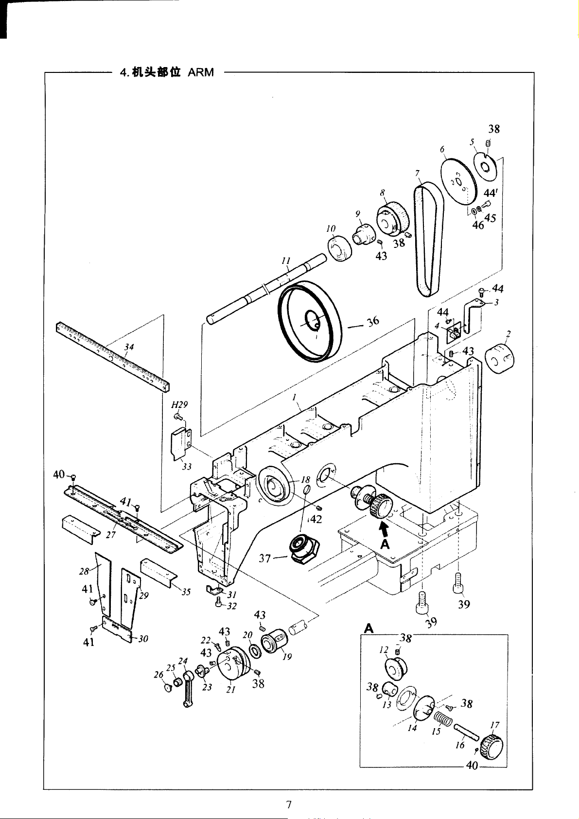
4
ARM
38
7
28
/
/
-;6
,/
-/.
//
https://manualmachine.com//
.......
-
/
/"
7
Page 10
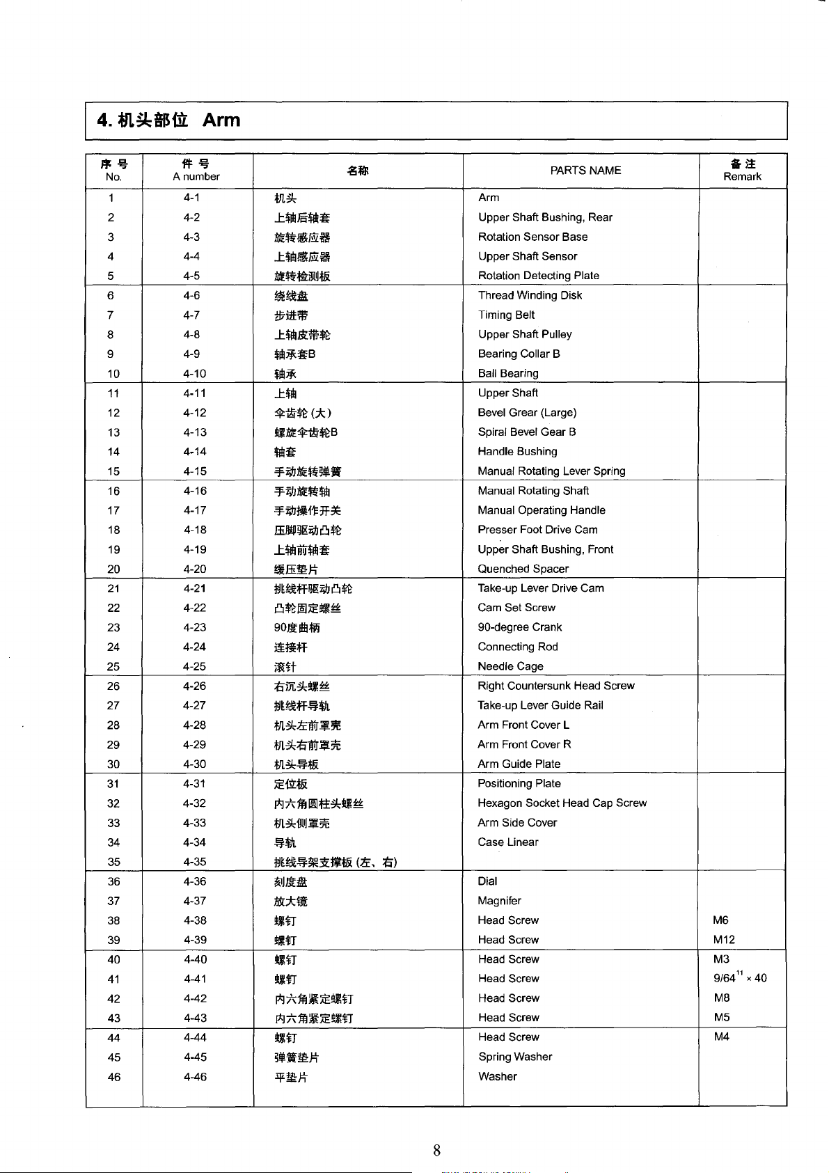
4.
*ll!k&IHlt
Arm
..
~
No.
1
2
3
4
5
6
7 4-7
8
9
10
11
12
13
14
15
16
17
18
19
20
21
22
23
24
25
26
27
28
29
30
31
32
33
34
35
36
37
38
39
40
41
42
43
44
45
46
A number
11=~
4-1
4-2
4-3
4-4
4-5
4-6
4-8
4-9
4-10
4-11
4-12
4-13
4-14
4-15
4-16
4-17
4-18
4-19
4-20
4-21
4-22
4-23
4-24
4-25
4-26
4-27
4-28
4-29
4-30
4-31
4-32
4-33
4-34
4-35
4-36
4-37
4-38
4-39
4-40
4-41
4-42
4-43
4-44
4-45
4-46
.gJ]{
m~
...t!'flllJ§!Ub~
tJJE~~E!Z~
...t$1b~E!Z~
tJJE~~Wl~t&
~t&:&:
:tl7i1HW
...t$1h&:m~
$1b~~B
$Ill~
...t$1b
ip:t;y~
<*)
~tJJEip;t;y~B
!'$~
-¥i'JJ1JJE~~.!Iiif
-¥i'JJ1JJE~!Ub
-¥i'JJ~f1=1f*
ffill!P~I&i'JJCI~
...t$1b"WJ$1b~
t~ffimJ:!i
M~tlfHI[gi'JJCJ~
CI~!E;iE~~
90Jlltll~
J!fl;jf
5f€H
tim~~~
M~t&iff~*ll.
m~tcwr~~
m~tiwr~~
m~~t&
;iEf.iLt&
I*J7\1Hmltt~~~
m~mtl~~
~*A.
M~t&~~~t$*-&
~JJlD.!
(lc,
ti)
Mc::km
~fl
~fl
~fl
~fl
I*J7\1nj{;iE!IIIH
I*J:t\jnj{;iE!IIIfl
~fl
~.!liiftll:J:!i
:iJLtll:J:!J
PARTS NAME
Arm
Upper Shaft Bushing, Rear
Rotation Sensor Base
Upper Shaft Sensor
Rotation Detecting Plate
Thread Winding Disk
Timing Belt
Upper Shaft Pulley
Bearing Collar B
Ball Bearing
Upper Shaft
Bevel Grear (Large)
Spiral Bevel Gear B
Handle Bushing
Manual Rotating Lever Spring
Manual Rotating Shaft
Manual Operating Handle
Presser Foot Drive Cam
Upper Shaft Bushing, Front
Quenched Spacer
Take-up Lever Drive Cam
Cam Set Screw
90-degree Crank
Connecting Rod
Needle Cage
Right Countersunk Head Screw
Take-up Lever Guide Rail
Arm Front Cover L
Arm Front Cover R
Arm Guide Plate
Positioning Plate
Hexagon Socket Head Cap Screw
Arm Side Cover
Case Linear
Dial
Magnifer
Head Screw M6
Head Screw M12
Head Screw M3
Head Screw
Head Screw
Head Screw
Head Screw
Spring Washer
Washer
Remark
9/64
M8
M5
M4
§it
11
X 40
8
Page 11
..------
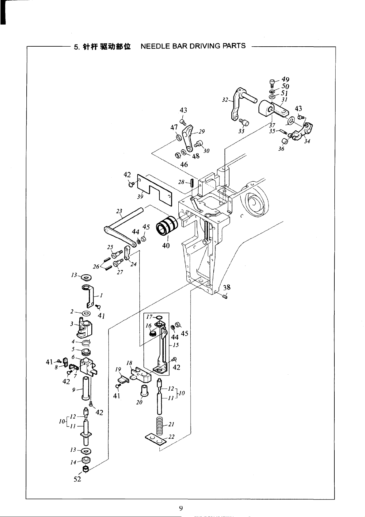
5.
ttff
lliibiHlL NEEDLE BAR DRIVING PARTS
9
Page 12
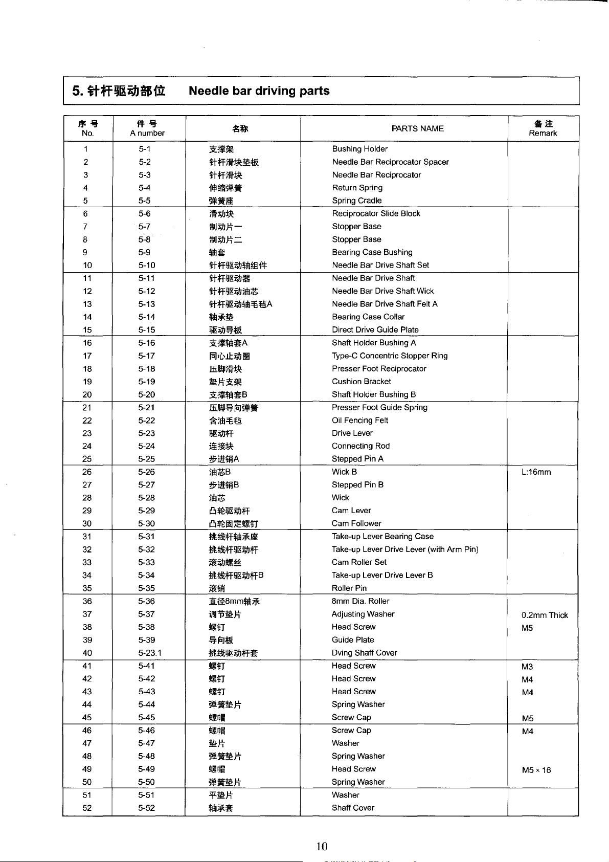
Needle bar driving parts
ff;~
No.
1
2
3
4
5
6
7
8
9
10
11
12 5-12
13
14 5-14
15 5-15
16 5-16
17
18
19
20
21
22
23
24
25
26 5-26
27
28 5-28
29
30
31
32
33
34
35
36 5-36
37 5-37
38 5-38
39 5-39
40
41
42
43
44
45
46
47
48
49
50
51
52 5-52
¥!=~
A number
5-1
5-3
5-4
5-5
5-6
5-7
5-8
5-9
5-10
5-11
5-13
5-17
5-18
5-19
5-20
5-21
5-22
5-23
5-24
5-25
5-27
5-29
5-30
5-31
5-32
5-33
5-34
5-35
5-23.1
5-41
5-42
5-43
5-44
5-45
5-46
5-47
5-48
5-49
5-50
5-51
5-2
~It
.~J~~
}tff)fl~W:t&
}tff)f}~
flf!mWUf
iW..Jm
)f}i"J.I~
!MMJ:tiMMJ:t=
*til~
ltfF~I&i"J.l$111ffi
}tff~J&Ma
ltff~J&i"J.l)fl:l~
ltfF~I&M*dl-=B:ffiA
*"t~W:
~l&i"J.l~*.&
3ZJ~$lii~A
15.1/L.\.lt.i"J.llll
ffiJJ!p)f}±)C
W:J:t.:Q:~
.:Q:~*Iii~B
ffill!il~icJ~.!Ii-
*5Etl-=B:ffi
!ll&i"J.lfF
iifl±Jc
i!ril!Ji!iA
5fi:I~B
i!ril!:ti!iB
jffi~
~*~l&i"J.lfF
~*~~~n
tJ~~fF*Iil~~
tJ~~fF~I&i"J.lfF
jf{i"J.l~~
tJ~~fF~I&i"J.lfFB
jf{jj!j
1H£8mm*"t~
lr.JiJW:J:t
~n
~icJ*.&
tJ~~~I&i"J.lfF~
~n
~n
~n
~.!11-W:J:t
~~~
~~~
W:J:t
~--W:J:t
~~lfl
iW..W:J:t
:iJLW:J:t
$111~~
f4=
Bushing Holder
Needle Bar Reciprocator Spacer
Needle Bar Reciprocator
Return Spring
Spring Cradle
Reciprocator Slide Block
Stopper Base
Stopper Base
Bearing Case Bushing
Needle Bar Drive Shaft Set
Needle Bar Drive Shaft
Needle Bar Drive Shaft Wick
Needle Bar Drive Shaft Felt A
Bearing Case Collar
Direct Drive Guide Plate
Shaft Holder Bushing A
Type-C Concentric Stopper Ring
Presser Foot Reciprocator
Cushion Bracket
Shaft Holder Bushing B
Presser Foot Guide Spring
Oil Fencing Felt
Drive Lever
Connecting Rod
Stepped Pin A
WickB
Stepped Pin B
Wick
Cam Lever
Cam Follower
Take-up Lever Bearing Case
Take-up Lever Drive Lever (with Arm Pin)
Cam Roller Set
Take-up Lever Drive Lever B
Pin
Roller
8mm Dia. Roller
Adjusting Washer
Head Screw
Guide Plate
Dving Shaff Cover
Head Screw
Head Screw
Head Screw
Spring Washer
Screw Cap
Screw Cap
Washer
Spring Washer
Head Screw
Spring Washer
Washer
Shaff Cover
PARTS NAME
§it
Remark
L:16mm
0.2mmThick
M5
M3
M4
M4
M5
M4
M5 X 16
10
Page 13
~~
~~
~
29
31
30
11
Page 14
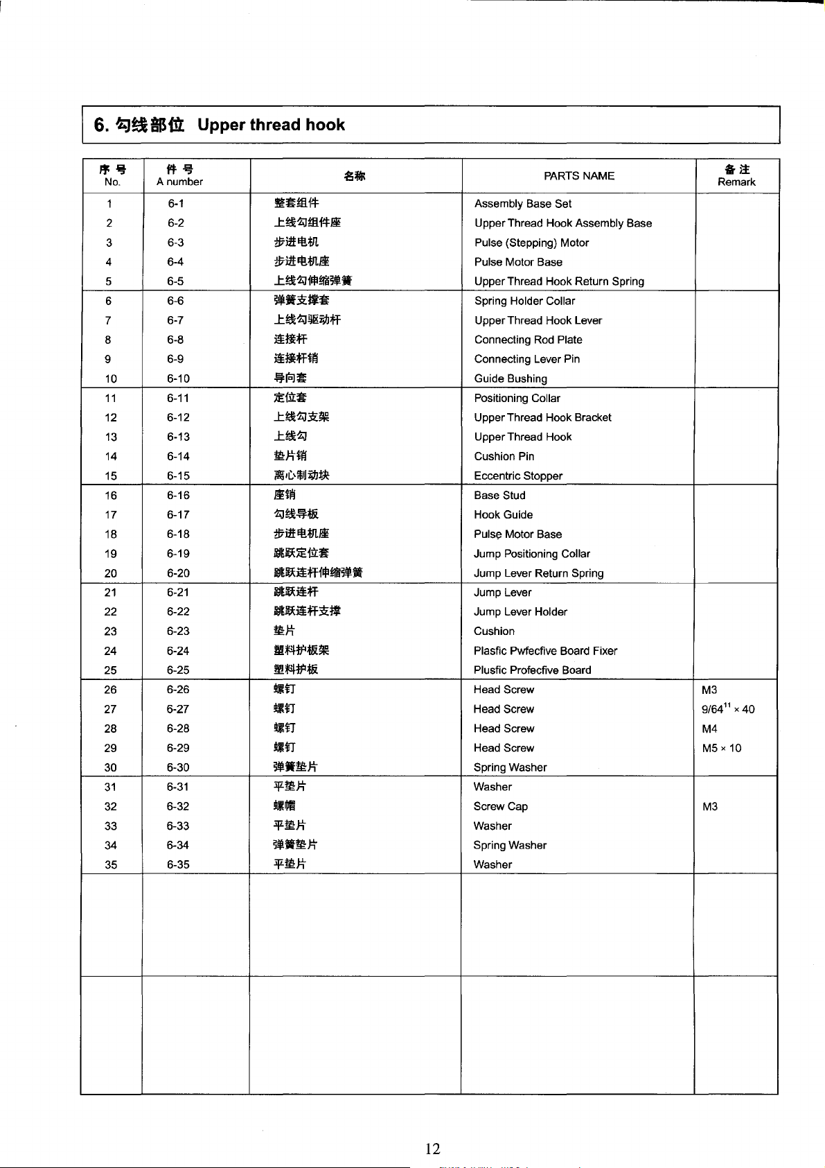
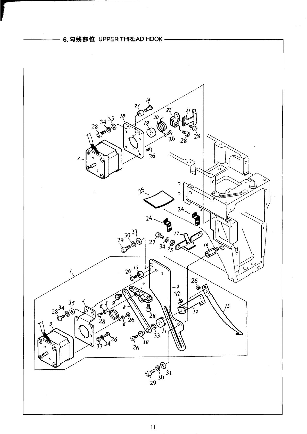
6.
~!:~&BilL
Upper thread hook
"~
No.
1
2
3
4
5
6
7
8
9
10
11
12
13
14
15
16
17 6-17
18
19
20
21
22
23
24
25
26
27
28
29
30
31
32
33
34
35
{fl:-i}
A number
6-1
6-2
6-3
6-4
6-5
6-6
6-7
6-8
6-9
6-10
6-11
6-12
6-13
6-14
6-15
6-16
6-18
6-19
6-20
6-21
6-22
6-23
6-24
6-25
6-26
6-27
6-28
6-29
6-30
6-31
6-32
6-33
6-34
6-35
.s~
fl~!llf4
..tt&~!llf4Ji
iUHt:Et!.m
i17l1t:Et!.M.Ji
..tt&~f!P~~~-
~~·Si·~
..tt&~
ijl&iliJ;ff
~tiff
~fl;fftili
~ic:J~
:iE:ffi:~
..tt&~Si~
..tt&~
W:J:!itili
iii
II)
ffid
ilbf:k
Jitili
~t&~*.&
ii7Hf:Et!.M.Ji
N3~~:iE:ffi:~
N3~~~;fff$~~~·
N3~~~;ff
B3~~~;ff1i.
W:J:t
m*4:tP*i~
m*4:tP*i
~n
~n
~n
.lilT
~-W:J:t
:iJLW:J:t
.lllll
:iJLW:J:!i
~~-W:J:t
:iJLW:J:t
PARTS NAME
Assembly Base Set
Upper Thread Hook Assembly Base
Pulse (Stepping) Motor
Pulse Motor Base
Upper Thread Hook Return Spring
Spring Holder Collar
Upper Thread Hook Lever
Connecting Rod Plate
Connecting Lever Pin
Guide Bushing
Positioning Collar
Upper Thread Hook Bracket
Upper Thread Hook
Cushion Pin
Eccentric Stopper
Base Stud
Hook Guide
Puis~
Motor Base
Jump Positioning Collar
Jump Lever Return Spring
Jump Lever
Jump Lever Holder
Cushion
Plastic Pwfecfive Board Fixer
Plustic Protective Board
Head Screw
Head Screw 9/64
Head Screw
Head Screw
Spring Washer
Washer
Screw Cap
Washer
Spring Washer
Washer
M3
M4
M5 X 10
M3
&it
Remark
11
X 40
12
Page 15
f
.------
7.
fl
SIS&
COLOR CHANGE SYSTEM
--------------.
@
(})
13
Page 16

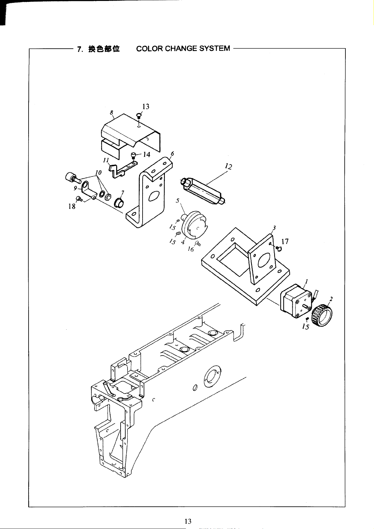
7.
-~tfJ{iL
Color Change System
*~
No.
1
2
3
4
5
6
7 7-7
8
9
10
11
12 7-12
13
14
15
16
17
18
ft:~
A number
7-3
7-4
7-5
7-6
7-8
7-9
7-10
7-11
7-13
7-14
7-15
7-16
7-17
7-18
7-1
7-2
~~
$'31!Et!*'l.
~
TJJ:Iif'l=tfiB
~~Et!fJlli
~~CI~
~~$111
~~Ji
DU$111~
~~~~
~E!Zli
Et!f.i'Lfi Potentiometer
!j}tiJf
~n
~n
~n
1*.17\"1iH\l~~n
~n
~n
•n
(Stepping) Motor
Pulse
Operation Handle B
Manual
Color Change Motor Base
Change Cam
Color Change Shaft
Change Base
Flanged
Change Cover
Sensor Base
Sensor Arm
Head Screw
Head Screw
Head Screw
Head Screw
Head Screw
Head Screw
Head Screw
DU
PARTS NAME
Bushing
G->:t
Remark
M4x6
M4x8
14
Page 17

I
....------
8.
ttffl:{
1
I
1) NEEDLE BAR CASE 1
--------------,
15
Page 18

I
8.
ttffi!
( 1 ) Needle Case (1)
.*%
No.
1
2 8-2
3
4 8-4
5
6
7 8-7
8
9
10
11
12 8-12
13
14
15
16
17 8-17
18
19
20
21
22
23
24 8-24
25
26
27
28
29
30
31
32 8-32
33
34
35
36
37
38
flf:~
A number
8-1
8-3
8-5
8-6
8-8
8-9
8-10
8-11
8-13
8-14
8-15
8-16
8-18
8-19
8-20
8-21
8-22
8-23
8-25
8-26
8-27
8-28
8-29
8-30
8-31
8-33
8-34
8-35
8-36
8-37
8-38
.Sit
it;ffJiffii~
it;ffJi
tt;ff
tt;ff1i:~~-
~¥-•mJ:t
=ERmJ:t
•~mJ:tB
mJ:t~~JE
..t?E,~lMi"JJ±R
7f~:ifM~n
tt;ffitfl~
ffiJI!P~ifA
ffiJI!P~¥-ifB
ffiJI!IIitfl~
ffi.II!Pffii~
ffi.II!P
ffi.II!P~
ffi.II!P~~!hl!n
mJ:tii!A
it~
tt~!hl!n
it
~~tl!;ff~i.i:L~
~~tl!$dl~
~~tJ!;jfffi
~~tJ!;jf
~tit~
~~tJ!;jf~~
~~tJ!;jfir.J
it;ff~tc:Jt&
l'~*A
..t~*A
~n
~n
~n
:lJLmJ:t
I*J7dn~~~n
tt;ff~n
i~
"'P
~
PARTS NAME
Needle Bar Case Set
Needle Bar Case
Needle Bar
Needle Bar Holder Spring
Spring Shoe Washer
Felt
Packing
Cushion Rubber B
Cushion Ring E
Upper Dead Point Stopper
Flat Fillister Head Screw
Needle Bar Connecting Stud
Presser Foot Spring A
Presser Foot Spring B (for Thick material)
Presser Foot Connecting Stud
Presser Foot Set
Presser Foot
Presser Foot Bushing
Presser Foot Set Screw
Cushion Ring A
Needle Clamp
Needle Set Screw
Needle (DBK572
Take-up Lever Positioning Bushing
Take-up Lever Shaft
Roller
Type
Take-up Lever
Thread Guide
Take-up Lever Boss
Take-up Lever Adjusting Bushing
Needle Bar Guide Rail
Case Rail, Lower
Upper Bur
Head Screw
Head Screw
Head Screw
Washer
Hexagon Socket Screw
Screw
#11
NY)
Take-up Lever Set
§it
Remark
M4
M3
16
Page 19

I
9.
NEEDLE
BAR
CASE 2
46
17
Page 20

9.
tt~~
( 2) Needle Case
{2}
"~
No.
1
2
3
4
5
6
7
8
9
10
11
12
13
14
15
16
17
18
19
20
21
22
23
24
25
26
27
28
29
30
31
32
33
34
35
36
37
38
39
40
41
42
43
44
45
46
47
48
49
14~
A number
9-1
9-2
9-3
9-4
9-5
9-6
9-7
9-8
9-9
9-10
9-11
9-12
9-13
9-14
9-15
9-16
9-17
9-18
9-19
9-20
9-21
9-22
9-23
9-24
9-25
9-26
9-27
9-28
9-29
9-30
9-31
9-32
9-33
9-34
9-35
9-36
9-37
9-38
9-39
9-40
9-41
9-42
9-43
9-44
9-45
9-46
9-47
9-48
9-49
.SfR
Top
Ni~~
~t~~!Uit
~t~~!t!itli
f'tif1l;ffffl
ffit.J~!t!tt
$~~
~t~~-
if.JiJ*fflA Stroke Adjuster A
1H£5mm*ffl
*dl~
}f{m1i:~fflf.t:
f!f
H*
~~~
mit&
~~•Mtm
l'i:t~fflf!f
l'i:t~~
~~~it!·
ffit.J~!t!-~
ffi~Jiffif!f
J:~fE~
:li~:l!
:li~~!t!·
:li~ffiil*
ffi~~!t!-
ffi~Ji
<*Ml*)
ffi~Ji
~:@:
ffi~~
ffi~~
<*Mi*)
ffi~*
~tsli
Cl~}f{tiliffif!f
m*
mit&
...t~~1i~
1'~~1i~
~~
.!i:~$111
-Fft
...tmit&1i~
mit&~ti$111
-Fit
]HJ~1i~
~icl}f{T-Ji
1*17\tfJ~~•n
•n
•n
Cover
Thread Take-up Spring Attaching Base Set
Thread Take-up Spring Attaching Base
Retracting Lever Set
Push Spring
Knurled Screw
Tension Collar
Thread Take-up Spring
Smm
Dia. Shaft
Bushing
Roller-type Large Thread Holder Set
Needle Roller
Thread Guide
Face Plate
Magnet Rubber
Lower Thread Guide Set
Lower Thread Guide
T_hread
Spring Presser Bracket
Thread Presser Base Set
Thread Holder Bracket
Thread Suspender Disk
Thread Suspender Spring
Thread Suspender Spring Presser
Thread Suspender Attaching Screw
Thread Presser Base (with Tape)
Thread Presser Base
Velcro
Thread Presser Lid (with Tape)
Thread Presser Lid
Thread Presser Spacer
Change Roller Base
Cam Roller Pin Set
Space Block
Face plate
Magnet Holder, Upper
Magnet Holder, Lower
Magnet
Holder Shaft
E-ring
Face Plate Bracket
Face Plate Hinge Shaft
E-ring
Switch Bracket
Sfand
Hexayon Sockef Screw
Head Screw
Head Screw
PARTS NAME
Hook Spring
fiji
Remark
18
Page 21

9.
~~-
( 2) Needle Case (2)
~~
No. A number
50 9-50
51
52 9-52
53 9-53
54 9-54
55 9-55
56 9-56
57 9-57
58 9-58
fl:-i!
9-51
.Sit
!l!l~lil
!Jfl
!kilT
!kilT
~~H~:Jt
!1!1~~
!kilT
!l!llr
!kilT
PARTS NAME
Screw Cap
Head Screw
Head Screw
Head Screw
Spring Washer
Screw Cap
Head Screw
Head Screw
Head Screw
§;1:
Remark
19
Page 22

10.
XraJII~IHtC
1)
X-AXIS DRIVE SYSTEM 1
------------.
31
0
29
6743
~G;J
20
Page 23

I
10.
XraJ~mi.bAIJfl:(
1) X-Axis Drive System (1)
,.-It
No.
1
2
3
4
5
6
7
8
9
10
11
12
13 10-13
14
15
16
17
18
19
20
21
22
23
24
25
26
27
28
29
30
31
32
33
34
f4:~
A number
10-1
10-2
10-3
10-4
10-5
10-6
10-7
10-8
10-9
10-10
10-11
10-12
10-14
10-15
10-16
10-17
10-18
10-19
10-20
10-21
10-22
10-23
10-24
10-25
10-26
10-27
10-28
10-29
10-30
10-31
10-32
10-33
10-34
.SWJt
x~illm
fE:Ji
JiJi
mtcJ~J~
mqw~R
mqw~L
X~
it
x~~*iL
liti~
~~~
~lfi~
X*dl~l&i~MW
~I&;;J]fli¥-ft&
x~m~
~it~~
~.It
U~j:E~
X*dlt~
-t-if
ill(~~}i:B
**IIftiJil~
Xtdi~IH.ll:7f*
~-Jil
1*1*1flj!~tl~
~~JiR
;iE{i'i:~A
:iEf.ll:~B
ffim~ttilB
!llltr
3f~J:t
!llltr
~if~
.It
!lll~fil
!llltr
PARTS NAME
X Sash
Z-spec.
Frame Felt
Base
Traverse Scale
Side
PlateR
Side Plate L
X Cover
X Linear Way
Joint Plate
Stack Plate
Detecting Plate
X Drive Belt
Belt Stopper
X Pulley
Needle Bearing
Washer
U-shaped Bracket
X-axis Pin
E-ring
Tension Stay B
Sensor Attaching Plate
X Limit Sensor
Holder Base L
Hexagon Socket Head Flange Screw
Holder Base R
Positioning Plate A
Positioning Plate B
Frame Presser Spring B
Head Screw
Washer
Head Screw
Spring Washer
Screw Cap
Screw
Remark
M4
M3
M4
A
it
21
Page 24

.-------
11.
XIDJ!Jiiib81Sm:C2)
X-AXIS DRIVE SYSTEM 2
----------,
5
~
7
5
¥
3
22
Page 25

11.
XJD]~l!ihtiJitf:(
2) X-Axis Drive System (2)
"~
No.
1 11-1
2
3
4
5
6
7
8
9
10
A number
fll:~
11-2
11-3
11-4
11-5
11-6
11-7
11-8
11-9
11-10
.SifJR
1iil~lllt!*'L
X~l&i;!Jffl~
~iH~sti:mtA
I@.*'L.!J~
!ltlfl
!ltlfl
~if:~sti:mtB
i*.J:i\:1f.l~~!ltlfl
~-'-if!ll:J:!i
m~!ltln
Servo Motor
X Drive Pulley
Tension Stay A
Motor Cover
Head Screw
Head Screw
Tension Stay B
Head Screw
Spring Washer
Head Screw
PARTS NAME
G->1
Remark
M4x6
M4 X 12
.•
23
Page 26

r-----
12.
Yf&Jlli~&Bfn:
Y-AXIS DRIVE SYSTEM
-----------
24
Page 27

12.
Y(ii]
~miJJABilJ:
Y -Axis Drive System
~-ij-
No.
1
2
3
4 12-4
5 12-5
6
7
8
9 12-9
10
11
12 12-12
13 12-13
14 12-14
15
16
17 12-17
18 12-18
19 12-19
20
21
22
23
24 12-24
25
26
27
28
29
30 12-30
31
32 12-32
33 12-33
34
35 12-35
ftl:~
A number Remark
12-1
12-2
12-3
12-6
12-7
12-8
12-10
12-11
12-15
12-16
12-20
12-21
12-22
12-23
12-25
12-26
12-27
12-28
12-29
12-31
12-34
.Sit
fii.Jnl~m
v~~m~
!Ill~
Y~~tH:iL:H-;,.;
v~~w~
-t•
v~&:mrn£!111tl'f
!Ill~
!11:111
jf{tt~~
y~
12mmtt~'if
Y$ill!}l&i;I:Jm~B
Y~J}I&i;I:Jffl
J}l&i;I:Jmtl1i~
XSi$L
XSi$R
Y~*lt
ffl:l:k
v~&:mrn£~1i~~
Y~ffl~
~:p
-~
$ill~~
$ill~
-ttf
!Ill~
!111M
!Ill~
~~wmJ:t
-¥tll:Jt
!hi~
!Ill~
~~•mJ:t
-¥tll:Jt
PARTS NAME
Servo Motor
Y Motor Bracket
Head Screw
Y Limit Sensor
Y Detecting Slit
E-ring
Y Belt Tension Pin
Head Screw
Washer
Needle Bearing
Y Shaft
12mm Dia. Needle Collar
Y Drive Pulley B
Y Holder Drive Belt
Belt Stopper
X Holder L
X Holder R
Y Linear Way
Stopper
Y BeltTension Stay
Y Pulley
Shuff Connection
Head Screw
Shaff Base
Shaff
Spring
Head Screw
Screw Cap
Head Screw
Spring Washer
Washer
Head Screw
Head Screw
Spring Washer
Washer
-~
25
Page 28

13.
~!iBIISil
1
TENSION BASE
26
Page 29

Thread Tension Base
,.-I!J
No.
1
2
3 13-3
4 13-4
5 13-5
6 13-6
7
8 13-8
9
10 13-10
11
12 13-12
13 13-13
14 13-14
15 13-15
16 13-16
17 13-17
18 13-18
19
20
21
22 13-22
23
24 13-24
25 13-25
26 13-26
27 13-27
28 13-28
29 13-29
30
31
32
f!l:~
A number
13-1
'13-2
13-7
13-9
13-11
13-19
13-20
13-21
13-23
13-30
13-31
13-32
.Sfllt
~~Jiffif!f
Mlfl~~Ji
ME~~~J:t
~~J:t*HI
!JJE~Ji
ME~J:t
~~li1fB
~~ii1filFar
iJWP"!blfl
~fiffii
)!t1J~f-
~~J:t
ffi7.l~*i
~~li1fA
~~*&
m~~n
••~n
ffi~~-
ffi~J:t
...t~~*A.
m~~n
~~Ji~
~~~E!L~*A.
®r~~E!Lii
TC~E!i:~*&
+!:f!M:&~*!fl
M!.Iz:~~Ji~~L
M!.Iz:~~Ji~~R
~n
~n
~n
~n
PARTS NAME
Rotary-type Tension Base Set
Tension Base
Rotary Tension Disk
Slit Diak Shaft
Rotary Base
Rotary Disk Slit Plate
Thread Guide Pin B
Guide Pin Roller
First Tension Thread Spring Screw
Spring Hook
First Tension Spring
First Tension Disk
First Tension Stud
Thread Guide Pin A
Thread Guide Plate
Countersunk Tapping Screw
Nickel-plated Screw
Thread Presser Spring
Thread Presser
Upper Thread Guide
Countersunk Tapping Screw
Tension Base Cover
Thread Breakage Sensor Rail
Thread Breakage Sensor Base
TC Sensor Card
Truss Head Tapping Screw
Tension Base Support L
Tension Base Support R
Head Screw
Head Screw
Head Screw
Head Screw
§it
Remark
3R*10
3P*8
3P*6
27
Page 30

....-----
14.
!1.88i1L
THREAD STAND
----------------,
14
4
(§)
1
\
36 I
--e
37 /
38
' ....
35
28
Page 31

14.~-AISUi
Thread Stand
"~
No.
1
2
3
4
5
6
7
8
9
10
11
12
13
14
15
16
17 14-17
18
19
20 14-20
21
22
23
24 14-24
25 14-25
26
27
28
29 14-29
30 14-30
31
32
33
34
35 14-35
36 14-36
37
38
39
40
41
ftl:~
A number
14-1
14-2
14-3
14-4
14-5
14-6
14-7
14-8
14-9
14-10
14-11
14-12
14-13
14-14
14-15
14-16
14-18
14-19
14-21
14-22
14-23
14-26
14-27
14-28
14-31
14-32
14-33
14-34
14-37
14-38
14-39
14-40
14-41
45~
fi~ll
fi~ij!~
Bi~
tE:!il:
l'fi$~3!l:~Ji
iJ;J"''pij!~
~.ittlfi
Bifi~.itji
BifiJ:!i
tE:!il:
Bi:h!kl~
i:tfi*.&
fi~:!Ltt
fi~
fi~A
fi~B
fi~C
fi~D
fi~E
fi~F
~fi:rlA
~fii=LB
~·~:lL~fiffi.i!f
ifal:P!ki!U
*:h~!t-
~fiJ:!i
Bi:h!kl~
i:tfi*.&
!klti.fE'lft
!klti.fE'lf2
!klti.fE~3
M!:P
!Ill
lift
:!JL!il:J:!i
!kilT
:!!LmJ:!i
~ji!il:J:!i
!kl~lrl
!kilT
rll:J:!i
...too.£
PARTS NAME
Thread Stand Plate
Thread Stand Stud
Tube Presser Pipe
Thread Stand Felt
Under Thread Tension Stay
Adjusting Screw
Spring Hook
Under Thread Winding Coil Spring
Thread Course Tension Disk
Felt Packing
Thread Course Tension Stud
Thread Course Thread Guide
Thread Stand Shaft
Thread Course
Thread Course A
Thread Course B
Thread Course C
Thread Course D
Thread Course E
Thread Course F
Thread Guide A (White)
Thread Guide B (Red)
No.1
Tension Set
No.1
Thread Tension Spring Screw
No.1
Tension Spring
No.1
Tension Disk
No.1
Tension Stud
No.1
Tension Thread Course
Spiral Tube 1 For
Spiral Tube 2 For 4,5, 11, 12th Needle
Spiral Tube 3 For 1 ,2,3, 13, 14, 15th Needle
Tube Joint
Screw Cap
Washer
Head Screw
Washer
Spring Washer
Screw Cap
Head Screw
Washer
Face Cover
6,
7 ,8,9,
1Oth
Needle
&a:
Remark
L=220mm
L=230mm
L=240mm
29
Page 32

.---------
15.
13~-!:1-·
UNDER THREAD
WINDER---------,
I
®-4
?.-@
..:>-s
8_.@)
9~
?
19
30
Page 33

15.
Elih~~~·
Bobbin Winder
"~
No.
1
2
3
4
5
6
7
8
9
10
11
12
13 15-13
14
15 15-15
16 15-16
17
18
19
fll:~
A number
15-1
15-2
15-3
15-4
15-5
15-6
15-7
15-8
15-9
15-10
15-11
15-12
15-14
15-17
15-18
15-19
.Silt
l'~~~~ffiftf:
1'~https://manualmachine.com/i
~~-
m!l
-r-•
~~*Ill
m111
~Mill
~~~
~~J:!i~-
:m:~•n
~~-~··
~~Cl~~~~~
~i1M~J:!i
:m:~•n
~~Cl~*ll!~·
-Ftf
•n
I*.I*RI~~-tr
PARTS NAME
Under Thread Winder Base Set
Under Thread Winder Base
Thread Winder Arm
Spacer
E-ring
Thread Winder Shaft
Spacer
Rubber Ring
Thread Winder Wheel
Thread Winder Plate Spring
Pan Head Screw
Thread Winder Arm Spring
Thread Winder Cam Shaft
Bobbin Presser
Pan
Head Screw
Thread Winder Cam Shaft Spring
E-ring
Head Screw
Head Screw
&>t
Remark
16P*8.5P*0.8t
Black-coated
E-6
1 OP*6.5p*0.5T
11/64*40*8
9/64*40*5.5
Black-coated
E-5
31
Page 34

.....-----
16.
11!-t86~
ELECTRICAL
PARTS---------------.,
32
Page 35

16.
El!
~AB{U
Blectrical Parts
~~
No.
1 16-1
2 16-2
3
4 16-4
5 16-5
6 16-6
7 16-7
8 16-8
9
10
11
12 16-12
13
14 16-14
fll:~
A number
16-3
16-9
16-10
16-11
16-13
.Silt
"Fmt&
lt!.Ji"~t&
WB!i~lll
WB!i~lll
!111m:
1'1!719.~*-&
i*lft~
~t&IJM:bll~
~=f
M3-10
1~=
E.!li&
mf;IJI'i!!'J
!!lifT
!!lifT
!!lifT
PARTS NAME
Case Cover, Lower
Computer Card
Resin Spacer
Resin Spacer
Stud: No.1: M3-10
Power Card
Fuse: Glass Tube: 125V-20A
Card Attaching Base
Coated Clip
Rear Cover
Transfer Cable
Head Screw
Head Screw
Head Screw
a a
Remark
33
Page 36

.------
17
.....
POWER SUPPLY
BOX--------------.,
34
Page 37

I
17.
..
~
No.
1
2
3
4
5
6
7 17-7
8 17-8
9 17-9
10
11
12
13
14
15
16
17
18
19
20
21
22
23
@lifO
~~
A number
17-1
17-2
17-3
17-4
17-5
17-6
17-10
17-11
17-12
17-13
17-14
17-15
17-16
17-17
17-18
17-19
17-20
17-21
17-22
17-23
Power Supply Box
-1SIJ\
*li-f*Ji
-~!ll:J:!i
DCEt!iJ!
Et!Vit
I!&
I&
ftl
Et!mt
ll&l&
ftF
G
GND~
...t.l'7f*
**~~
%iJ!fii~
f*~~
DC%iJ!m~~~
%)XI.~
ii'f*~
~B~
Et!iJ!~DC
Et!iJ!~AC
Et!iJ!~AC
!Ill
if
tli!~JE:iE!IIIiJ
*fi-f*~!lllir
)XI.~JE:iE!IIIiJ
!blir
-~
...
PARTS NAME
Case Base
Cushion Rubber
DC Power Supply
Surge Absorber Assy L
Surge Absorber Assy FG
GND Cord
Seesaw Switch
Switch Harness
Fuse: Glass Tube: 250V 6.3A
DC Power Supply Harness
Fan
(Power)
Case Cover
Handle
Power Cord DC
Power Cord AC For USNCanada
Power Cord
Head Screw
Head Screw
Head Screw
Head Screw
Head Screw
Screw Cup
AC
For Europe
~
Remark
35
Page 38

.------
18.
Ef!I!Mfl OPERATION
PANEL-------------.
36
Page 39

r
18.
Ef!~SSi:!L
Operation Panel
Jt;~
No.
1
2
3
4
5
6
7 18-7 FDD
8 18-8
9
10
11
12
13
14
15
16
17
18
19
20
21
22
23
24
25
26
27
~-it
A number
18-1
18-2
18-3
18-4
18-5
18-6
18-9
18-10
18-11
18-12
18-13
18-14
18-15
18-16
18-17
18-18
18-19
18-20
18-21
18-22
18-23
18-24
18-25
18-26
18-27
t,IHt:~m-,
itt&Ji
HHl=Wt&
LCDW!;J'Elfi~
LCDWMElii
m-~~t&
FDDEI!~J
.%l~~.lt3f*
tii1=m-rE~
GND~
t~i1=~m,
DIPff*
-~
tii1=~1J1;t:tm~•Ji
tti1=~1J1;t:bllfE~
tti1=~~~
JE;£~
FDDll.-ft
•n
•n
•n
•n
•n
!ll:J:!i
-~!fj
f:t~~-
.Sit
-wnm
(2)
~w
PARTS NAME
Operation Panel Case, Front
Keyboard Base
Operation Panel Keyborad
LCD Seuled Plate
LCD Seal
Console 2 Card
FDD
FDD Cable
Emergency Stop Switch
Operation Box Bracket
GND Cord
Operation Panel Case, Back
DIP Switch
Knob Screw
Panel Attaching Stay
Panel Attaching Bracket
Operation Panel Harness
Nylon Clamp
FDD Unit
Head Screw
Head Screw
Head Screw
Head Screw
Head Screw
Washer
Screw Cap
Support
Of
Bracket
--~
Remark
37
Page 40

Sill
GENERAL VIEW
17
Page 41

r------19.JVat[tf!H41
BASE
FRAME
ASSEMBLY
1-------,
~~
'«
26
25
38
Page 42

19.
mmmHtt:
ff
%
~14~%
1
Ref.NO. Part NO.
I
2 19-2
3
4 19-4
5 19-5
6 19-6
7 I 9-7
8 19-8
9 19-9
10
II
12
13
14
15
16
17
18
19
20 19-20
21
22 19-22
23
24 19-24
25 19-25
26 19-26
27
19-1
19-3
19-10
19-11
19-12
19-13
19-14
19-15
19-16
19-17
19-18
19-19
19-21
19-23
19-27
BASE
FRAME
~
~
ASSEMBLY
1H·rJJJili
1~
[-
tnl1if.t~
i*J
;\
m
'Bi
J:E
~~
tJ
i'RJISM~
+
'f:t~
iJL
:!k
~~
n
!t-IJ*:#t.
i*J
;\m
12lltt:!k~~n
ll'!l!d~H
1~\j
ti];~
~~H
)tt~l~~i?;
1:1XJ&:%:
https://manualmachine.com/:):
++~fl:Ydt~n
tiXJ
f'f:
tiXJf'f:~~
tR
i~·iJJitX~
i*J
;\m
121ltt~~~n
Sf~~
i*J
;\m
l2lltt:!k~~n
Jtt
16¥:
~~~~lll
i*J
;\
ml21l
u
~
~~
n
T~lil
13~
1
Parts Name
Slide angle
Needle bearing
Bearing pin
Hexagon socket set screw
Spacer
Cross recessed countersunk head screw
Skid plate
Hexagon socket head cap screw
Frame set screw
Cap frame base
Presser screw
Base holder roller
Rail plate
Nut
Cross recessed pan head screw
Drive wire
Wire guide ring
Plate
Slide nut
Hexagon socket head cap screw
Flat gasket
Hexagon socket head cap screw
Base bracket
Base holder shaft
Hexagon socket head cap screw
Flat gasket
Block circle
~tt
Remark
39
Page 43

....--------20.
~m$14
17'1!
1~
2
BASE
FRAME
ASSEMBLY
2------,
~
38
4-19
28 3
0
~
02
tf{1
~
14~
12
Jr:?
40
Page 44

20.
~m$14
2
BASE
FRAME
ASSEMBLY
2
~
~ftj:~Ji}
%
Ref.NO. Part NO.
I
2
3
4
5
6
7 20-7
8
9
10
II
12
13
14
15
16
17
18
19
20 20-20
21
22 20-22
23 20-23
24 20-24
25
26 20-26
27
28 20-28
29 20-29
30 20-30
20-1
20-2
20-3
20-4
20-5
20-6
20-8
20-9
20-10
20-11
20-12
20-13
20-14
20-15
20-16
20-17
20-18
20-19
20-21
20-25
20-27
!6
l*
*1!~
~~Hi!
1"ir&
I*J;\ifi
'f~~
;\tHP~£1
ill~flUdrh
ip~
;\
3if!m~~
T~~
l21li't:Yd!-~UH
tit
ki
$tll
:M
ili~
L;J:
Jzpg]
tJJi
xtHEL1tJ=
Ef0~
*1i~ll'li/E~A
I
¥t~iJL~P~tl
~IX:iJJJf
rr
**~t&
)±~
+
¥t~
:m:
~I[!,~
tJ
LLH~
kH
'fVi'~tf!
1i:if~#im
'f~
:tiff~
~if
~~tH¥m
~0:
i}J
1;!;
~
Lid frame
Base frame
Visor bracket
Hexagon socket head cap screw
Flat gasket
Hexagon nut
Base frame shaft L
Base frame shaft R
Hexagon nut
Spring gasket
Flat gasket
Clip stopper
Pinch lock
Clip fitting set
E-ring
Lid frame fittings A
Cross recessed countersunk head screw
Drive ring
Center block
Presser spring
Truss head tapping screw
Lever bracket L
Releasing lever L
Lock pin
Lever spring L
Lever pin
Lever bracket R
Releasing lever R
Lever spring R
Drive base
Parts Name
~a:
Remark
31
32 20-32
33
34 20-34
35
36
37 20-37
38
39
40 20-40
41
42
43
44
45 20-45
20-31
20-33
20-35
20-36
20-38 EJ!F E-ring
20-39
20-41
20-42
20-43
20-44
k'-71~~
~'-]~~~
JJD
[!1]
tft Reinforcing plate
~tft
4'1
tft
~tft
~~)LA
~~)L$ffi
;\
iTJP,__~£1
3f-J.{c~
'c#$)L
B Guide roller B
rt\
T
'1
I
'c#'f~
;\i+J~~£J:
5¥~~1'il
Tm~
Guide
Guide
Guide bracket
Needle plate guide
Guide roller A
Guide roller shaft
Hexagon nut
Plain gasket
Eccentric guide pin
Hexagon nut
Spring gasket
Flat gasket
baseL
baseR
41
Page 45

-·
- 21.
4~
~~$14
17)7
4-19
v41
BASE
•
ASSEMBLY
37
31
I I
32~
I I
tJ
,
39
3
0
12
~
/.//
14~
42
Page 46

21.
~~$14
J¥
%
Ref.NO.
I
2
3
4
5
6
7
8
9
10 21-10
11
12
13
14
15
16
17
18
19
20
21
22
23
24
25
26
27
28
29
30
BASE
~ftf:~%
Part NO.
21-1
21-2
21-3
21-4
21-5
21-6
21-7
21-8
21-9
21-11
21-12
21-13
21-14
21-15
21-16
21-17
21-18
21-19
21-20
21-21
21-22
21-23
21-24
21-25
21-26
21-27
21-28
21-29
21-30
t1!S4€
~'§t1i
f4tlY.
r*J
;\m
']'~!]
;\f+J~~£1
lrt;ltl£LL$rn
1/J\:'1
tl£
;\if.l1~~
1£flm~WJ
T-~~
)Z~
tPi
;JUH1:l14
E~~
tffi
S4€
1
:=i-q~1JL~
~!Riyi]Jif
r-r
j(t~11Z
J.E:w
+
]':
LLH~
kH
tlJi~tfj
1i:H1ffi~
t~
;t;H~
;{_;;ff
1'1H5~~
v~1$
ASSEMBLY
f$
~
l2i!U~!l~~J
;t;
Hl
L;J:
It'll
IE~
A
~~n
t~
:m:
:'k:
P~
'FJ
Parts Name
Lid frame
Base frame
Visor bracket
Hexagon socket head
Flat gasket
Hexagon nut
Base frame shaft L
Base frame shaft R
Hexagon nut
Spring gasket
Flat gasket
Clip stopper
Pinch lock
Clip fitting set
E-ring
Lid frame fittings A
Cross recessed countersunk head screw
Drive ring
Center block
Presser spring
Truss head tapping screw
Lever bracket L
Releasing lever L
Lock pin
Lever spring L
Lever pin
Lever bracket R
Releasing lever R
Lever spring R
Internal support
cap
screw
~a:
Remark
31
32
33
34 21-34
35
36
37
38
39
40
41
21-31
21-32
21-33
21-35
21-36
21-37
21-38
21-39
21-40
21-41
stt¥
~lR:
1!!~11:
IJlli!EJ±t&-
mJ
!E!DHIZ
[Q]
~.c~tiZ----::
v~
;\
JAJ
;\
;\flH~£1:
ltri!EJ=l
!AJ
;\
____:_
m
fQl
u
J~
t~
n
if:J
rwlHJJ~'H
m
/01
tt~t~n
Support
Cushion block
Bolt
Fixing plate 1
Fixing plate 2
Fixing plate 3
Hexagon socket head cap screw
Hexagon socket head cap screw
Hexagon nut
Fixing lever spacer
Hexagon socket
head
43
cap screw
Page 47

.-----------22.
~~$14
1
PEDESTAL
ASSEMBLY-------
44
Page 48

22.~~${4
PEDESTAL
ASSEMBLY
1¥
~ftj:~%
%
Ref.NO. Part NO.
I
2
3
4
5
6
7
8
9
10
II
12
13
14
15
22-1
22-2
22-3
22-4
22-5
22-6
22-7
22-8
22-9
22-10
22-11
22-12
22-13
22-14
22-15
-15
~
~J±
t.kt&
)f.<;!±
.p
5'
,fjQ
Jf!;;J¥
r·IS't&
Lr::Jf!;;!'¥.
;tJ
!~!'¥.
Jit:fU"$
~Jjlql
$~-f
fi;J
/\
:M
l2ll
U
:'k
~~
Pi
/\
m
l2l!
tt
:'k
m~
/\mm~-1¥
§
JJ:!l!~!fJ
Pi
/,
m
12]
tt
:'k
m~
/\mm~HJ:
+~II
'H
n
n
Parts Name
Base upper table
Base middle table
Base lower table
Left base
Right base
Connecting support
Washer
Wheel
Hexagon socket head cap screw
Hexagon socket head cap screw
Hexagon nut
Tapping screw
Hexagon socket head cap screw
Hexagon nut
Flat gasket
~a:
Remark
45
 Loading...