

Page 1
TABLE
BLIND
STITCH
MACHINE
~
PARTS
1i
PARTS
.
llJ
1!1
ZOJE
1*
ffl
•
llJ
Jl.tt m
SEWING
-=¥-
BOOK
tji
BOOK
mt
PJ.I
iliilll211:1 § HIH.H5J
MACHINE
CO
..
LTD
Page 2

~
~
........................................................................................................................
1'
1Jlmi1\llit···············································································································2
1
2, 'E'!l'liDi'W!l!!····························,············································································2
3, IJ!Hil'l'ii'!lt'lllli'f'Flft;'lr·····························································································3
1'
!llmiil'l'ii'!lt························································ ·················································3
( 1 ) Ill
Y<
il'l
Jjj(
ill· ........................................................................................................ 3
(2)tn.~ag~~---······································································································4
3)1Jl#.o
il'l'ii'!lt
( 4
)l'El&!ll
........................................................................................................
f'fil'l'li'!lt
..................................................................................................
·4
·5
2, !l'f'Flitril'lllilr··············································· ····················································6
( 1
)lliUit!Jl%.!
· · · · · · · · · · · · · · · · · · · · · · · · · · · · · · · · · · · · · · · · · · · · · · · · · · · · · · · · · · · · · · · · · · · · · · · · · · · · · · · · · · · · · · · · · · · · · · · · · · · · · · · · · · · ·6
(2)1Jlw~"'············································································································6
.
(3lfllHil'lii1Jill··
4, lllmiil'llt!!l·· .......................................................................................................... 7
1'
'Eiiltil'lltrlil'!llltlB!···································""""""""""""""""""""""""""""""""""""""""""""""""'"··7
2,
!Jlttill;l'l'···· ..................................................................................................... 7
3, !il!>-'llllttoci't·· .............................................................................................. a
4, Ill Hillli<f:lnt · ·
5,
ll'!>J\"i!··· .. ···············,································"·"""""""""""""""""""""••··················· ..
6'
!ilii'!il'l
7,
.l'iittil<'li···························· ............................................................................
8,
j!J¥43f~Jlt~lJ*:i':····-
5,
IJ!Hil'Jil!l!i!··
1 ,
!>ilH<O
2,
lflt~j¥ff[agira]1)
3'
!hii'!l&!h:tJ
4,
Ill
tt
-'lHl&fii:'liiJlll'i
{1
)!W"J§ti:ii·
.. · ··
· ······ ···
··
!h}..jllljj(
··
· · · · ·
· · · · · · · · · · · · · ·
..
ill· ............................................................................................
..................................................................................... 10
···
·· · ·· · ··
· · ···· · ··· ····· · ··· · · · · · · ........ ·
ll!
il'liJlll'i
· · · · · · · · · · · · · · · · · · · · · · · · · · · · · · · · · · · ·
.....
-·
................................................... ---.-----
iJlll'i
...............................................................................................
· ·
···
· · · ···
.... --............................
··
...
···
·· · ..
· ........ ·
· · · · · · · · · · · · · · · · · · · · · · · · · · · · . · · · · · · · · · · · · · · · · · · · · · · · · · · · · · · ·
··
· ..... · · · · · · ·
-·
............................................ --.....................
··
·· · ..
··· · ··
...
·· .. ··
· · · · ···
· · ·
···
·· · .. · ···
··
..
· · · ·
......
· · · ·
..
·· · ..
··
......... · ..... · ........ ·
··
· ·
··
····· · ······
· · · · · · · · · · · · · · · ·
· · · · ····· ·
..
.......................... ·-·12
···
·· · ·· · ·· · ·· · ···
...
··
· · · · ····· · ··· ····· · ·
· · · · · · · · · · · · · · · · · · · · · · · · ·
..
.. · ··
· · · · · ···· · ·
· · · · · · · · · ·
· · · ·
··
···
..
· 7
.. · ·a
···9
·9
10
··
·11
·11
·12
·· · ·13
·13
(2)li'ifJ.tf;i:'li
(3)1Jl
tt-'"
........................................................................................................
:li'llHRf;i:'li
..
· · · · ·
..
· ·
.. · ..
· ·
..
· · · · · · · · · · ·
..
· · · · · · · · · · · ·
..
· · · · · · · · · ·
..
· · · · · · · · ·
..
· · ·
..
· · · · · · · · · · · · · · · · ·
·13
·14
Page 3
(4)j}!Jtjj!jji:
5,
<!/~)Z,.j}!Jtf!Iiifl'JiJll1'i
(1
J<~~~&>'<fl'lliPI<
(2)
IIlli
...................................................................................................... ·····15
..... ····· ...................................................................... ····15
mil·... . . . . . . . . . . . . . . . . . .......................................................................... 1 5
;z
fl'J:ti":t>lll":ii
................................................................................................ 1 6
(3)<1//&J<fl'J
( 4 )lllii>Z
6,
l~if!l$1\,..
(1
)ti":t>I!I:ii·
~flii!I:ii·
fl'llltr
F.ii!I:ii
ffiif!)l&fl'Jf;)-iiiJOJ1'i
............................................................................................... 1 7
................................................................................................ 1 8
.................................................................................
............. ····· .........................................................................................
18
18
(2)WiF.ifll":l!············································································································20
(3)
lllif!l>l\fl'JI!i'il<
7'
ffilll!Jffi:IJ
8,
m!~~*:IJ
6,
f!\$":1;>\;
..............................••.........................•...........•..........
.....................................................................................................
fl'JiJll1'i·
fl'JiJll1'i
...................................................................... ····· ................ ····20
........................................................ ····· ..................................
··•·· .......•...•. ·····•··· ····22
·20
·21
7, jJ!,jUifi'F····································································································· ·········:22
8, l!l!!ilJIIIi'F···································· ··········································································22
9,
r.§llJiH>~'·
10,
'!l'i'FfPI<··
1'
2,
3'
4,
5,
..............................................................................................................
..........................................................................................................
.f:JL~;flliiilffl'ffi14=······················-··························-··············································24
:Eilill!!i'F···
i!Sif!l
)f:W>tlllll!!
lll!&>Zllli'e·····
itl&l!!J'F
......................................................................................................
....................................................................................................
............................................................................................................
'
f!F·
..............................................................................................
23
23
26
·28
30
32
6,
l~if!I$1\:WIIlffill!Jl!!i'F··
7'
lllif!l>l\J-.il!J.!!.hltitl!!f'F··
8,
lll1mEEillll&.II:illlm#··
9,
ll<!&ii:l.!!.!!ii!J;l!!j'f'
10,
ltl&l!!f'F
........................................................................................................
...........................................................................................
........................................................................................
...........................................................................................
................................................................................................
34
36
39
40
42
Page 4
TABLE OF CONTENTS
ForeWord····································
1.
Brief lntroducion to The MOd8J·· ····· · ··· ·· · ····· · ·· · ··· ··· ·· · ·•••· · ···•· · ··· ··· ·••·· · ····· · ·•••·· ····· · · ·· ··••· · · 2
2.
Main
TeChnical
3.
Mdachine Installation and Operation Preparation···················· ...
1.
Machine
(1)Unpacklng machine
(2)Fitting machine
(3)Fitting
(4)Fitting
2.
(1)Cieaning·······································
(2)lnspection····················································· ..
{3)Lubrication··············
4. Opeation the
1.
2. Needle
machine
Work
Operation preparation
Rotating direction and sewing speed
Specifications···················································································· 2
installation·································································································3
head·······················································································
franme·····························································································4
head·························································································
plate components
.............................................................................................
............ , .................................................................................
Machine--· ....... · ..... · ........ · ........ · ........ ···· ..... · ..... · .. · ..... · ..... · ..... · .. · ............ · 7
selection--.. · .. ·
..
..
···············································································1
·····································
.................................................................................
........................................................................
··································"··········
of
main
shaft···--···
· .. · .. · ..... ·· .... · ..... · ........... · ........... · .. ·--· ..... ·
..............................................
..
··----·
..
·· .... · ..... ···· ·8
.. ·· 5
..
·····
3
4
6
6
6
6
7
7
3.
Specifications--..... · ..... · .. · ........ · ..... · ..... · ...
4. Needle
5.
Threading········ ......
6. Feeding and
7.
Skip
8. Regulating feed dogs height·· ..... ·
5. Adjustment
1. Regulation
2. Adjust men
3.
Regulation
4. Position regulation
(1)The front and the rear
(2)The positioning
(3)The
replacemet--..... · .. · ..... · .. ·
·································
pulling
stitch device·· ........ · ........ ·· .... · ..... ····
of
the Machine··
of
stitch length··--
of
blindstitch sewing penetration--
of
the pressure
left
limit
position
out
of
..
of
needle and needle plate
of
position··---
of
location·····--·--··--......................................................................
of
the needle
··
... · .. · ..... · ..... ·--· ........ · ........... · ........... · ... · 8
..
· ........... · ..... · ........ · ..... ·
... ········· ... ··············· ......
sewn materials
....
· .. · .. · ..... · ..... ·
................................................................................
of
material retainer· ........... ·
...........................................................................
..................................................................
..
· ..... · ..... · .. · ..... ·· ....... ·· .... · ..... ····
· ..... · ........ · .. · ............ · .. · .. · ..... · ..... · ..... · ...... · · · ... ·
..
···· ........ ·· ....... · ..... · .. · .. · ........... · ..... · ..... · ... ·
.............................................................
........................................................
......................................................................
....................
..........................................
· ........... · .. ·
························
..
· ........ ··
----8
·9
g
10
10
11
11
12
--12
:--·13
13
14
14
Page 5
(4)The limit of needle throw··············
5.
Regulating position of needle and thread hook··
(1
)Basic position of thread hook·· ........ · ........ · ..... · ..... · .. · ..... · ........ · ........ ·.·· ..... · ................... 15
.........................................................................
.............................................................
15
15
(2)Positioning of location for pronged thread
(3)Adjustment
(4)Positioning Of lOcation of thread hook
6.
Regulating position of ridge forming disc and material retainer·--·· ........... · ........ · ..... · .. · ...... · 18
(1)The left and right position.................................................................................... 19
{2)Regulating of the front and the back posution......................................................... 20
(3)Disassembling and fixing ridge forming disc·--......................................................... 20
7.
Regulating presser pressure ....... · · · · ..... · ..... · ........ · ..... · ..... · .. ·
8.
Regutating thread tension
6.
Mode of Sale·· .. · .. · ....
7.
Machine Head Accessories
B.
Machine Frame Accessories··---............................................................................... 22
9.
Warranty Period·--·· .................... ·
10.
Parts Book
1.
2. Main shaft components··"··
of
the position of the
·•
..... · ..... · ..... ·· .... · .....
............................................................................................................
Machine casing and lubrication components··"·"
th'
....................................................................................
..................................................................
.................................................................................
hook--
............................................................
'3ad
hook
..................................................................
.....................................................................
..
· ..... · .. · ..... · ..... · .. · ... · 2 1
··
.... · .. · .. · ..... · ..... · ..... · ..... · ..... · .. · ..... · .. · .....
, .................... 22
............................................................................
.....................................................
·•
·16
17
18
21
22
23
23
24
26
3.
Feed dog and needle shan componentg
4.
Thread hook components
5.
Needleplale components··
6.
Ridge fanning disc and lifting presser
7.
Disc oscillating and skip stitch components-
8.
Disc locking mechanism and
9.
Thread tension and nipper parts components··
10.
Work plale components
..................................... ; ..............................................
..................................................................................
componenls·--··--·"''''"'"'"'"'"'"'"''""'""'"·
knee
lifting presser shaft parts···
....................................................................................
..................................................................
·· 34
...........................................................
....................................
.....................................................
•·
28
ao
32
36
38
40
42
Page 6
li'!Oh~tJLUJttftiH<ili\ifi
J:k:lll P
®--1'-l'ii
Jl.#.
:;jqltllf
Ill r
9'
WEll..
J>r.J!<.
il>'fa'Jllt-~.
Ill
f'
fl!HI!Wilril<il2fs:t1J.a'Ji<l!lll;f!!l/.\lllt1J·i!;,
tL
r~llif~II1".
@EI"®Illlf'lxifmlJL#WJlll.
¥Iiili
~
((
i<l!lll
i<l!lll.
if'!§>>
!l~~'i'l-:!Jil!i'ltt-llJ\'-1-'.
,
M~Ji\Hl'.
%.
4'11L*fflttffiit~.
lliflit<{Jt.
f!l.
Xif'i'l-51>'1'/ill~lll'®li!i'l.
'1'/illifiJJl;a'JIM'll'.
tJL~®i<l!lll~.
#iirlf&JI!ii&:IJ.
i\Jl~:klll?9.
'JCA9\fllliA;Ii;lllJi#4=i.li'l§'j;,
jg,lfp~Jl.%-.
Jt;;iJ~tl/1iJ!i10.
ltli!O!i/UJ.
H@!i,llJMEi:'!"f'f
'l'~~~r~~~.ffi~ti'B~fti,llli<l!lll;f!l!l~WW~'le.
~?.f-2fs:t1J.!J\f!;;f!!i,llllit:tfll<.
m-l!!UM-'f!!~Jfnll;
~Hll'.
llfili!l*lll'.
(frnmtt.
~.7fi>li/!Ul.l!lffltf8JJI!ilt~i,llllli!!
lii#~~J
~(Jt6t:li:J¥tfLD1l!l.
Foreword
Y.llil'l!ll
!li~;f!l'l'l'Jli!Alil
1031!'1-"P-~lii'i\':~j!J;,
;f!!i,llll'1J'l<11Lf!l.
~~l:kllll"~
litti'B!Ii'.@
~
M
£!ifii!!Y.7U!lta'J
blindstitch sewing machine, another
conglomerate is
of
either Chinese-style
literature covering maintenance, operation, and principles, has been available on domestic
market.
To help customers have a good mastery
"OPERATION MANUAL"
ministrative.
The model adopts needle bar thread take up and swing thread hook system
needle and a thread hook may form stitch
equipped with a regulating device for presser pressure, thread tension, stitch length, blindstitch
penetration, height
needle, ridge forming disc are changed and particular mechanism regulated
now
dedicated
or
of
feed dogs and blindtitch space etc. Only when appropriate parts such
to
customers. This
Western-style clothes such as garments, skirts.
of
is
specially written for reference
tYPe
Model
the essence
103
chainstitch
product
is
widely applied
of
operation and adjustment
of
service men, operators and ad-
and
newly developed
to
blindstitching
Up
to now, fewer
so
straight blindstitch .
C3J.1
the Model meet
by
of
it, an
that an arc
It
is
also
as
. 1 .
Page 7
the needs
by numerous customers.
ated
1.
1.
of
sewing various sewn materials
on
It's lifetime depends
or
repaired regularly.
Read instructions carefully before operating the machine.
not only manufacturing
of
different thickness. Thus it has been well received
quality
*)l.gjiifiji)-
Brief
Introduction to The Model
but also whether it is properly
operk
ZJBOO
~~~m.~~mr~~~~~~~~AA~~~~I~.~~~o
>l<Jit!!IIJ
Ai!!ii~WJI!>I~~
*ilt!lif!Jlti!l'.
~~~.;~;,~~~~~~~ilt~z-.~~~~.
materials such as trouser
clothes etc.
The model
mance, smoother running,, precision fit, longer lifetime, aesthetic stitching, easier operation. It
is one
of
indispensable pieces
Welcome to patronage.
1.
:±:~tt*ni'.m
ll'JHlfliHil;l;,-#$1Jl\<f*'iillJI!!J1'.f
,
lllfii/J~¥;10;)~,
Jf>Jl!i;
103ll'J$~~
.k~Tm~~<~
<
~fl<tL
iJtltil"'<ll.
ZJ600
has
blindstitch sewing machine is ideal for blindstitching medium weight
leg seam, lower hem
fullowing features: Advanced construction, unique design, excellent perfor-
r)
~~!t"JJ.
1illllttR.
of
sewing equipment.
"'~'f~
..
of
garment,
!lf,!'l!i!],,
~~11\'.
and the fronl
~i':.
of
~;!Etle*·
West-ern-style
:10!
1.
Main Technical Specifications
2500
(I)
Ji1<""~~JJJ!!>:~
(2)
lllf!E~WM
1t /7)-
2000<f
. 2 .
/7)-
Page 8
< 3
>>JOiiH<Il
W~lilliJIEtt
3-8
1:1
il!:J!t
2:1
<s
> Billlli'l\IE
< 6 >
JlUIHII.fr
m
JIUilli!
(
8)
1!!11L:W
< 9 l
1IL
(JO)til~ll>:!li:
(l)Maximum
(2)Normal
(3)Stitch
(4)Blindstitch
(S)Lift
(6)Needle:
(7)Thread~
Ill!
>I!
JUt-!!>
sewing
length:
clearance
sewing
speed:
space
of
speed;
ratios:
presser
foot:
7il!;jf(
GLXI
14.
270W
SlOX
2500s. p. m
2000s.
'!)!
NM75-!00(LWX6T#3-#4l
5-7.
Stex
360X245(
24.5~Jf
p.
m
3-Bmm
1:1 2:1
7mm
NM75-100
14.
S-7.
Stex
.:t!D!iG~
of Modle
cotton
¥:X
14.8-7.
jt
X~)
GLX
thread
4tex
ICLWX6T3#
or
~1\11~
14.
8-7.
-4#)
4tex
polyester
(8)Eiectric
(9)0verail
(10)Net
3.
;f!L~rt;J'ti;~:fDi~f'F;ft~
3.
Machine
1.
Machine
o
>til
M~~~~~ti!JI,~.T-~m$ti!AL~~B'J~$~.m~~~.ull!l~~.tr~~m~$~
flli\'H'f
Fo,
motur
power;
dimension:
weight
installation
Jl,
B'J
1±19:~1f!ili
of
machine
Installation
l!H!:
fflxt~~
head:
and
1\iil'ii;
270W
SlOX
24. SKg
Operation
T-ll!*l'r:iffil
cotton
360X
thread
245(LXBXH)
Preparation
i'!~tft'~,
1!.1
!Mi
!1:~1'1',
il~
'EF
•
3 .
Page 9
(1
)Unpacking
machine head
Unpacking
macnine head
nent
parts
li.!.t
to
avoid losing
( 2
)Vi.!!!!
CD
"11
machine head from its packing box. Be
such
as
and
accessories,
l¥J
,_.,ill;
Jt
m111
thread tension
parts
and impairing production.
~
ffl
fi!IIH!l111!
don't
assembly
throw
111-"i
li' :t;
any packing material
;tJ
and
tiuead
~:it~
.
l'i'
* l'ii ill
sure
not
guide etc.
about
Ill
fll ill
to
damage projecting
After
unpacking all compo-
without
il!i
fll
checking
It
jji
il!i
if.!;;
parts
of
the
packing
l'iH!l1illffi
:it
Ill.
®'ilffjl.ijl)Vi.-"iaill:it!ll.
ailllUJ!Il!!!!J:
®'ilf
Ill;;;
•
@'ilf
1:
•
l'
Iii
lf
EJi'i,'ilf/i1illllJ~,:j{fj;ijq'jj1;!1,1lJJi;,~/i1J&Ji;{i'l.
(2)Fitting
(j)
machine frame
Frist
connect
?l-MU
-"i
rear
iii
.
.p
II!
VI.
.!Uilill tr 1-f:it
stand
lliJ!Ill1ll
side
fl
a
ill
support
'II!
~Jr.lHf
It
,
and
ttl'
treadle
Fo
Ill
1: lli
l1ll
fl
aill*l$!>Ifll m ll'ilf a ill
lf
It
!k •
ill~
If
li1illl¥J
shaft
beam with side frame
li'
:t;
-'i!lli!!!
fl!il011f
(left
Ill
and
right),
ers,
ter
to locate the treadle.
1:. Jf
l::t<Al~ll>"l",
~t'f\jjllJ)i;<IIJ
and then link up
®Mount
@Put
the
and fix
@U;>nnect
regulating
c 3 l Ill!!<
W!.:
<D'ilf
!ii;llt l'li
li£11l!
fli'LFo
@:j{f
If
Jll!!l
@!ll;J: -.
treadle
the
motor
table
the
table and machine frame with washers
upper
position
ill;
li
:j{ffJl!
Jfill~&O<~I1l!Ql!(fl>,
ff"
2).
!li
* "N.. •
onto
onto
and lower
of
treadle
'fi!"D",
Q'J•i<
K ".!l.l'
li'
with
the
machine
pull
(left
Vi.
ill
Jii;llt "C", !llill
ill
~lt"F"
f\jj
"L
"-"i
:t;
fl'""
treadle
table.
frame,
rod with motor and treadle
and
lio
il!i
l!!lil.
w.'ll.
shaft beam by treadle
partition
right,
h\l:l'IJ
:j{flll!l,lll;i;l'Ei/W:l:CI!I
Ji!ilii!
:it
~t
the
and
high and
l'lilifll
Hl!
!l1;
II!
"B". l'li!i'fi!"E".
A
l't.
,
If
Ill
m
lil~t
table
at
wood screws.
low),
9'.
II<
lk
!!l
lf
1J!
lf
-"ill!
!k"'
shaft
and treadle
the
centre with four table
lever.
put
on pull rod
fix the treadle.and pull rod joint
Ill
!k "A"fl<
l'l:
l'li¥4'11!
"G".
!).
ll\i
i/ill
"J"Ji!ilii!
m
x<
II£Fo
*
I!!
lX.ll!:l'IJ a ill
'l"fll"H"
Be;<\\
mm;;;
shaft
joint.
Y'i
I
tEa
base.
wash-
Fo!t
)f
!I'll>/
illl'
Af-
•
lll'P
II!
m,..
ill:i!l'/l.
~t
&:
**
~
!1£
T'ili'ii:
:~~:
;5
•
•
.:!-
•
Page 10
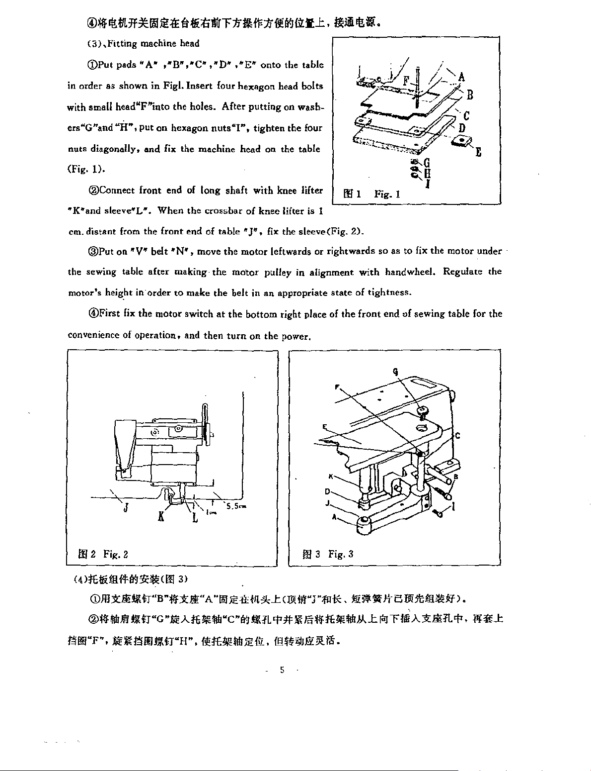
(3),Fitting
machine head
(!)Put pads
in
order
as
with small head"F"i.nto
ers"G"and
nuts diagonally,
(fig.
1).
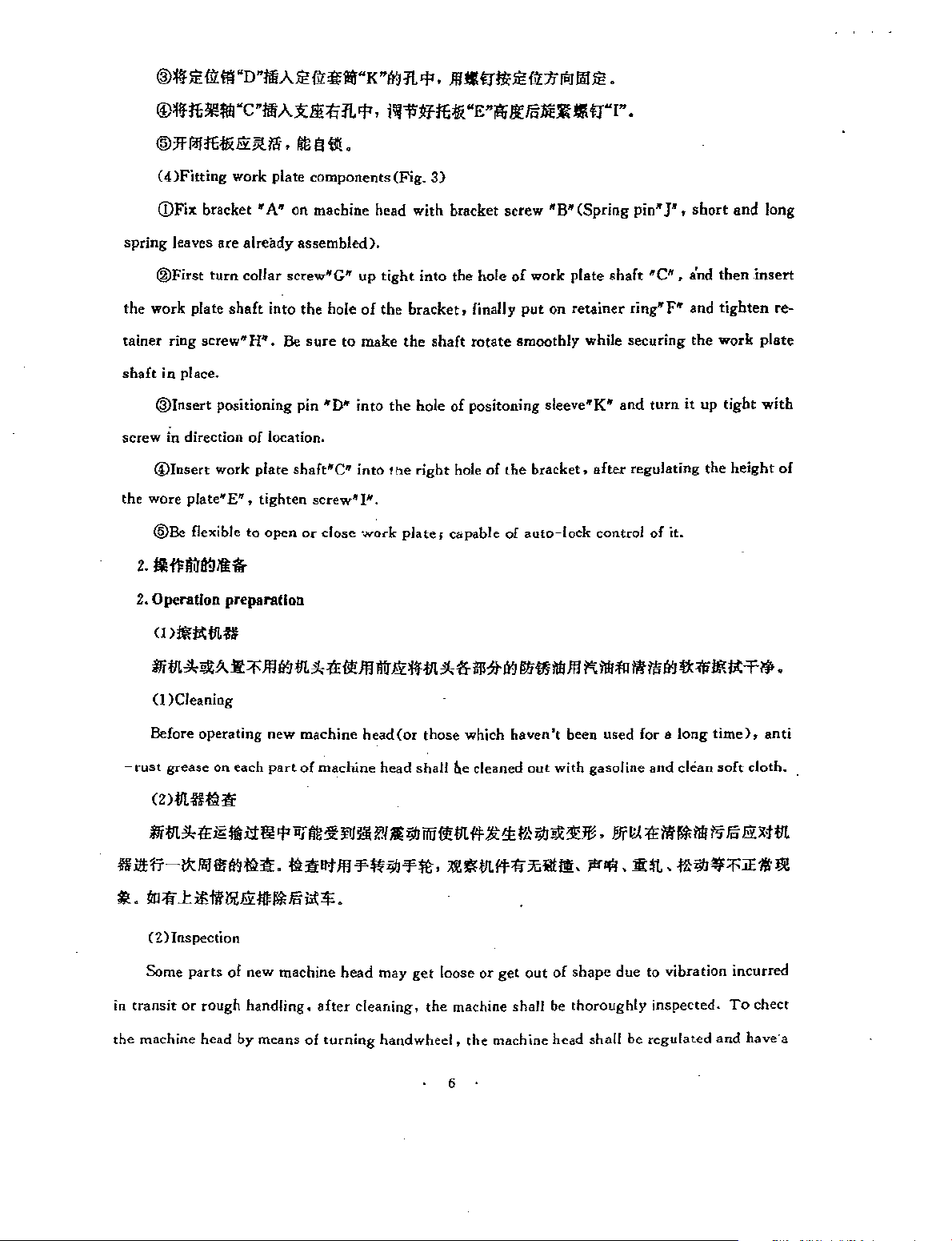
®Connect
"K"and
em.
the sewing table
motor's
convenience
sleeve"L".
distant
@Put
heig.ht in-order
@First
"A
shown
"H",
put
front end of
from the
on
"V"
fix
the
of
operation,
• ,
in
Figl.
on
and
When
front
belt "N", move
after
motor
"B"
,"C" , "0" • "E"
Insert
the
holes.
hexagon
fix
the
machine head
long
the
crossbar
end
of
making-
to
make
switch
and
then
four
hexagon
After
nuts"l",
shaft
table
the
the
motor
the
belt in
at
the
turn
onto
the
head
bolts
putting
tighten
with
of
"J", fix the
motor
bottom
on
on
wash-
the four
on
the table
knee lifter
knee
lifter is 1
sleeve(Fig.
leftwards
pulley in alignment
an
appropriate
right place
the
power.
table
or
llfl
2).
rightwards
with
state
of
tightness.
of
the
front
""G
~H
of
sewing
I
motor
table for the
Fig.l
so as to fix the
hand wheel. Regulate the
end
under
0
t..51
,..
I
'
'J
I!!
2 Fig. 2 m 3 Fig. a
w
;'tj!i
!II ffW!i'
CDJll
x!IH.Ofi""B"¥fx).;f[" A
®¥flil!ii"l
111
1!1l"F" • .oi'
:i1t
ffl!ill_
,/=''\::'•,_
K
ll<
<IE
!¥
fl"G ".oi'A!t
ffllil.\7.
WH"
3 l
L
lil!lll!
,
ll!lt!¥1
"
·s.s-
"lilllE
"C";<j
1t llleU:
ll\IL
lll!
lE
ffi •
<ll!
lii"J "f!! * . llHI"'f
'I'
it:!(
l!ll'i
'lllbie
5
§*f;'tlll!lii!M.J:
!l!Jii •
It
Bffiltli!ll<!lf
i"J
Tlili A
xJ.;ffl1.
l.
'I' •
l'l''l!'l:
Page 11
@jlfjl;
Ill:
Ill
"D"Ii!lAJE
(l):il!'ii!"K
"ii'J'/1.'1',
!llll!tr!JilE
fll::IJ(oj
JIIJE
•
@jlfjU!!lll
"C
"!ill
®'lf/l!Jlijj(fi!i<lli.
(4)Fitting
CDFix
spring
tainer ring screw"H"".
shaft
screw
the
leaves are already assembled).
®First
the
work plate
in place.
@Insert
in direction
@Insert
wore
@Be
work plate components(Fig.
bracket"
turn
collar screw"G" up
shaft
positioning
of
work
plate
plate"'E".
flexible
tighten
to
Ax81:ti
11.
'I',
l~ll'flJlijli_
"E"i!li
!l'Fo.o;;Jt
f!lllllll!.
3)
A" on machine head with bracket screw
tight
into
the
hole
Be
sure
to make
pin
"D*
into
location.
shaft~~"C"
open
oc
into
screw"
dose
of
the
IN.
work
into the hole
bracket,
the
shaft
the
hole
!he
right
plate;
of
hole
cbpable
of
work plate
finally
rotate
positoning
put
smoothly while
of
lhe
of
auto-lock
1.!\
~~'B"
(Spring
on
retainer
sleeve"K"
bracket.
<!"I".
shaft
and
after
control
pin"JW
• short and long
"C",
ring"F"
securing
turn
it
regulating
of
it.
a'nd
and
the
up
the
then
insert
tighten
work
tight
height
re-
plate
with
of
2. Operation preparaUon
(1
>ll!litll!ff
mm*~~•~m~m*~~ffl$fijlflll**$*~~~Mm~M~~$~~~ll!lit~~.
0 )Cleaning
Before
-rust
grease on each
operating
new
part
machine
of
machine
head(or
head
those
shall
which
1\e
cleaned
haven't
out
been used for a
with
gasoline
and
long
dean
time),
soft
anti
doth.
<Z>ll!fftHf
mm*~"'lll;;:
Ba~-~~@~~~-~~~ffl¥~;;tJ¥~.~~ll!#~~~m.~~.I~.W;;tJ~~~~~
~
• m
~
J:
i£iiii>Lfi
(Z)lnspection
Some
parts
in
the
transit
or
rough
machine head
m
.p
11'111<
Fo
of
new machine
handling.
by
means
BJii!l1!:
iit * .
after
of
turning
l'J
ll!l!!i
head
cleaning,
At""
may
hand
w
!>!
get
loose
the
wheel,
m #
:~t
or
machine
the
machine
1o
get
t<
""~
out
shall
'l!'ll' •
of
shape
be
thoroughly
head
shall
Elfl'l<E~I*
due
be
M t5
to
vibration
inspected.
regulated
Fo
fi>tll!
incurred
To
and
have·a
chect
6
Page 12
test in case
some
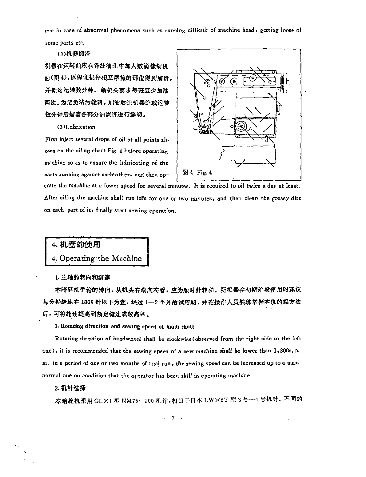
( 3
I!Lfl'~E~~ff~*tt$K~~A~~~WIJL
$
<1!1
ol
abnormal phenomena
parts
etc.
)IJLfl'
if<
1ft
4)
,l!lllHiEIIL#ill:!iJl!li!01li!!Ui
such
1i
as
running difficult of machine
!lJ
if<
lit.
head,
getting
loose
of
~11<!!
~~-~~~~~~«.~$~~11Lfl'~~E~
n:St#~~~*li!!*~~*~~~w.
First inject several
own on the oiling
machine
parts
erate the machine
After oiling the machine shall
on
iE
~lt:St#.
(3)Lubrication
so
as
running against each>other, and
each
part
of
4.-
Operating·the
drops
chart
to
ensure
at
a lower speed
it.
finally
flii!L
!1,
J!>lt
of
oil
Fig.
the
start
Machine.
4-
before
lubricAting
run
l;j;!lf.¥
at
sewing operation.
all
points
operating
then
for
several
idle
for
ol>
of
bn
sh-
the
op-
one
$
minutes.
or
m
two
4.
minutes,
Fig.
4
It
is required
and
to
oil twice a
then
clean
the
day
greasy
at
least.
dirt
].
"'lilf.l~
;f>:~~IIL~m~~M.~IJLJI,~~M~~.ff~~~#~~.flii!Lfl'~Wlll~&~m~m~
li>:SJ-#*1:!!~
E·~~*ii!~~~~~*l:i!~~~®.
1.
Rotating
Rotating
one),
it
is
m. In a period of one
normal one
2-
jlt~>lill'
;tlllf*I:IJLJlO!l
loJ
'ID!iiii
1soo
fti!CF~'ii:.
direction
direction
recommended
or
on
condition
GLX
and
sewing
of
handwheel
that
two
monthS
that
the
!l!l
NM75-100
!\!>'t
the
sewing
operator
1~21-
speed
of
shall
be
speed
of
~:1al
run,
has
lil.#.il!!'!'f S
. 1 .
Jl
~~mill.
main
shaft
dockwise(observed
of
a new machine shall
the
been skill in
#~!;.ii'AJJ;~t,O:!tlll!;f>:IJL~lll:lfl*
sewing speed can
operating
;f>:
LWX6T
from
be
machine,
l!13
the
right
be
lower
increased
't-4
side
than
up
'tilL
to
the
left
],
BOOs.
p.
to a max.
!'I'·
'l'i"J~
Page 13
2.
Needle selection
The
Model
3ft:-
4
f:t:
priate
size.
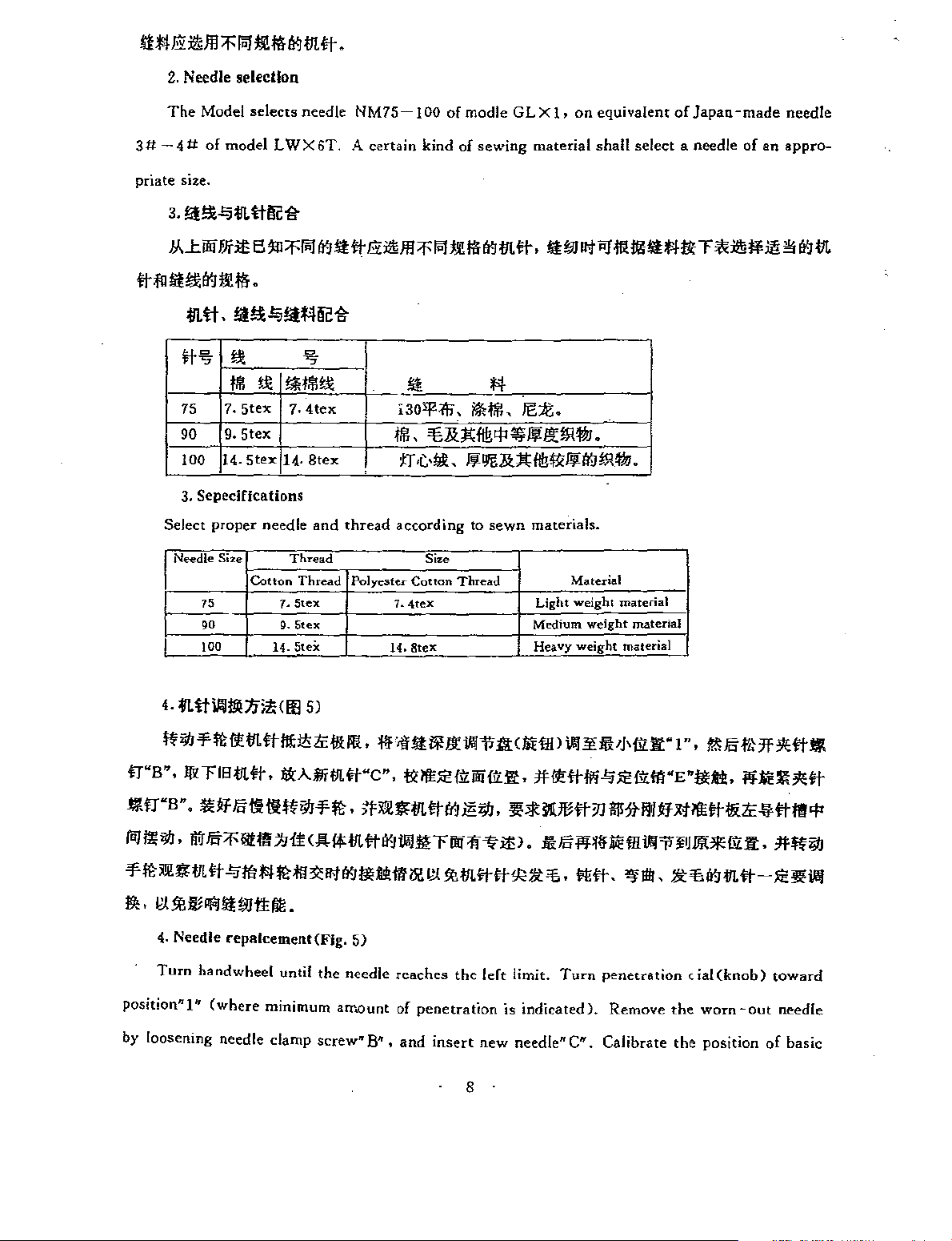
3.
f;t!£-'Oi!.ttr.!~
~Loom~s~~~~~~@~m~~~m~m~.~w~~~*~~~T~~~~~~m
ftf!l
!tl!l<
il.tt.!lf!la-'O!i*'lr.!~
selects
of
model L WX 6T. A
~
11
IJi
•
needle
NM75-
certain
100
kind
of
of
modle
sewing
GL X 1,
material
on
equivalent
shall
select
of
Japan
a needle
-made
of
an
needle
appro-
Select
4.
~>
tr"B",
J:ll
tr"B
W'3
75
90
100
3. Sepecifications
Needle
7.
9.
14.
proper
Size
75
'"
!00
!!!
!Nit!!
5tex
5tex
5tex
needle
Cotton
~!Nit!!
7.
}4.
Thread
7.
!).
14. SteX
il.ttWl!O:IJi'IHtll
iJIJ-¥
mit
m
tt
l!l:i!i
l!<
TIS
m
ft
,
lli:AIJT
".
!lUf Folt ll!
I>
~
"5
4tex
8tex
and
Thread
Stex
Stex
SJ
ti
iJIJ-¥
thread
Polyester
liHI<
IJ!
WC",
IB
,
~
_!t
i30'l':ffi".
*if
i*lli!.
JEt.
lli!.'B.&l';fl!l<P'I>Jll!itlll#J.
IT
according
1.
1<1.
•
'ilf
01
l'l!
~m
•C•!ll..
Cotton
4tex
8tex
!t
!l<
~IJil.&J!:fl!ll!IJll!(t,J!)l#J
to
sewn
materials.
Size
Thread
Light
Mfflium
Heavy
lJi!
~r
!1!11'
:lll:
< liun )
I!EJE
{!1.
iili
fii.ft •
#I!
tt
It!;!;
iJIJ
,
J!:;Jt
Material
weight
weight
ll!"'
ttli'i
1/IU!Ht
•
material
weight
material
material
>~VHJz.r
-'0
lE
j1J
'ill:St~l
1 • •
fii.
ill
"E
~Xi'
~For&
"lUi •
I!E
~l!tti
7f
;~~ott
•
jlj'
i1;
:I!;/<~
-ll'
~lll
'I'
(i!J
1!
iJIJ
•
Jitr
Fo
~II!
If
1.1
it
<,!;,
U:m
tt
~
illl!iH
oo
1f
~
ltl
.
.ll:
Fo
i'i'1~
-¥m~~m~~m~~m~~~~~~~~~m~~~£~.~~.~®.£~~mtt-JEJ!~
p,.
~~llill'J~Wttlll<.
4.
Needle
Turn
position" 1"
by loosening
repalcement(Fig.
handwheel
(where
needle
minimum
clamp
until
5)
the
needle
arnount
screw"
B",
reaches
of
penetration
and
insert
the
left
new
limit.
is
indicated).
needle
Turn
C"'. Calibrate
8 .
M'
Ill
il'li\'JIJJ!OIE
penetration
Remove
cial(knob)
the
worn-
the
position
fii.ft • JHt
toward
out
needle
of
basic
iJIJ
Page 14
surface,
Turn
be
kept
and
make
the
shank
come in
handwheel slowly and observe
in line
with
the left needle guide groove
CO'ltaCt
the
with
po~ition
movement
and
swing.
pin"E".
of
needle.
Be
sure
The
not
blade
to
touch
of
arc needle shall
the
groove.
(Procedure
orginal place,
ing
needles
of
adjusting
disc to avoid
be
replaced.
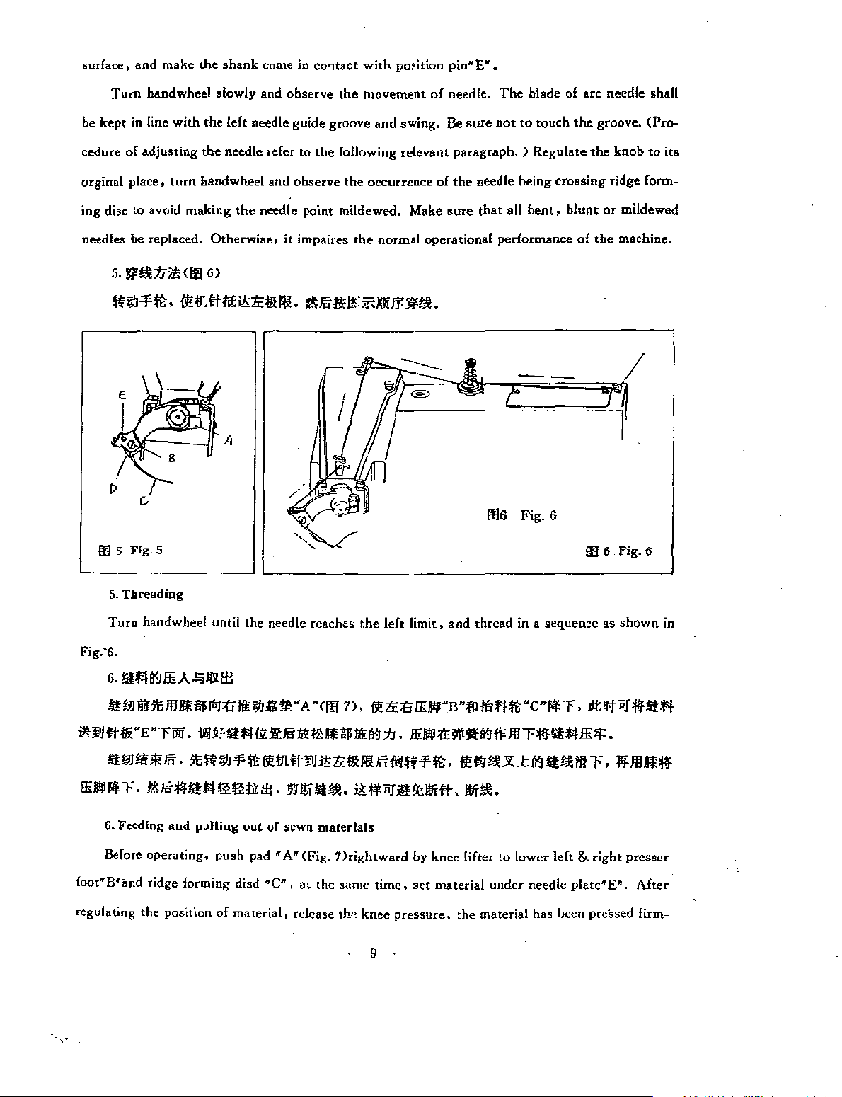
5.
!i'!l:IJ>ll<lfl
«~f~.~m~m~£~m.~s*oc~~~~!l.
the
turn
handwheel and
making
Otherwise,
6)
needle refer
the
needle
it
to
the
observe
point
impaires
following relevant
the
occurrence
mildewed. Make
the
normal operational performance
-7~£----,t~~.,r
r
0':15 Fig. 5
paragraph. ) Regulate
of
the
needle being
sure
that
all
bent,
lll6 Fig. 6
the
crossing
blunt
of
the
IE 6 Fig.6
knob
to
its
ridge
form-
or
mildewed
machine.
~~
5.
Threading
Turn handwheel until the needle reacher;
Fig.·6.
6.
Ill
l'l
!9
IliA
_,.lilt
1fl
l'f
w ll"lltJ!l
il'tj!Jft
l&
"E
!li:W!Ii
IEIIII!fol;T.~s'ifltl'l~~m~.~~lt!al.~~iiJ~~~~.~!l.
6. Feeding
Before
foot"B"illld ridge forming disd
regulating the position
If
lil!"'
""Filii • il!
*"'
.
5t
and
pulling
operating,
:fi
111
~am·
Jfl'fl'li.\1:1!';.6
~>
""f
~
!l! m
~"J
out
or
sewn materials
push
pad
"A"
~c~~,
of
material,
release th,, knee
A·
1!:
l!HUI!Ill'
(Fig.
at
the
the
<00
' > •
i'l'£:fi
(!<)
~
tcl!U!lsiflt>
?)rightward
same
time,
9
left
limit,
and thread in a sequence as
!EI'I"B
:h
•
IEIIII'!'E
by knee lifter to lower left &
set
pressuce.
·m
!I'
jil'(l<)
¥IE • "'"'
material
~he
m u
~
11'
J!l
!l!.l':
J:(l<)
under
material has been preSsed firm-
•
cnlfol;
r •
lit
n;-
r'IHtl'IIE lf: •
ltiai
11t
r • N
right
needle plate"E"'.
shown
iiJ
'if
!Ill*
presser
After
in
nu
'If
Page 15
ly
with
presser
foot
by
action
of
the
spring.
When
sewing
operation
is
finished,
first
turn
the
handwheel until
the
thread
and
cut
the
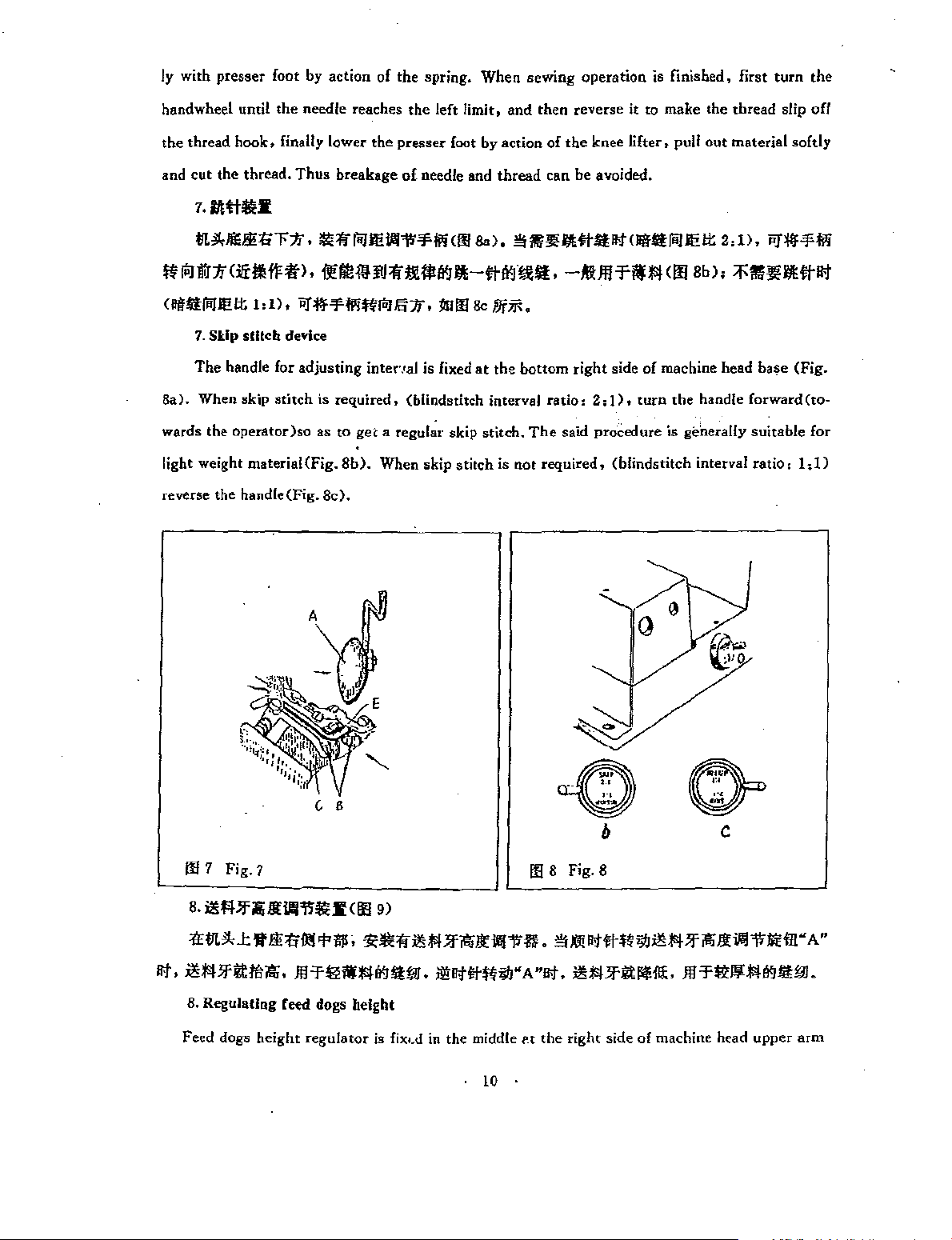
7.1/ttt~I
IlL
!I, JlliEIHir:lf •
ff
ill!lU:If<lfr!IHI'if>,
( i!lfftfoill!!
7.
Skip
The
handle for
8a).
When
wards the
light weight material<Fig.
reverse the
the
hook,
finally
thread.
!t
siUc:h device
11kip
operator)so
handle(Fig.
Thus
I •
1)
, PJ:jlf-J'jjljffilJ Iii
adjusting
stitch
needle reaches
!10
~M!11!JIJ:ffi!U!VJI!t-ttl¥.il'.llllt,
is
as
8c).
lower
the
breakage
=If
foil
11!
intenal
required,
to
get a regular
8b).
When skip
the
left
limit,
presser
foot
by
of needle and
IIIli'
-J'jjlj
(
00
& > ,
:If , 11100
is fixed
(blindstitch interval
Be
skip
stitch
at
stitch.
and
action
thread
!1!
/)fjj; ,
the
bottom
is
not
then
reverse
of
the
knee
can be avoided.
II
'lif
/llitt!t
-AlJI!
right
ratio:
2:}),
The
said
procedure
required,
it
to
make
lifter • pull
I>H
II§
lit
foil
'fMJS!
side
(blindstitch
<ill
of
machine head
turn
the
is
the
thread
out
material
11!
!t
2 , D , PJ'ili-l'lili
Bb),
~\lliJ!IIIittlit
handle
forward(to-
geD.erally
interval ratio 1
suitable
base
slip
softly
(Fig.
l;D
off
for
C B
IE
7
Fig.
1
B.
~fil)fji;!f{l/llii'~Jf(lf!9)
lit •
'iffiLJI,
i!JS!
B.
Feed
J: 'It
!l!t;
Jfttltl~
Regulating reed dogs height
dogs
•
height
fll!
<I'
lill•
'!<~'If
Ill
'fi£iW#I¥.it!liiJ,
regulator
is fix..d in the middle
i!S
lSI
)f~
Ji'
J!!litttffijlj" A "lit,
. 10 .
lll'll'
III B Fig. 8
fi
. l1j
X!!
-'!#
f'_t
the
right
b
lit ttff;;!) i!S#
Jftti'l'il<,
side of machine head
)f
Ill
'ft!(JJJS!il'lilflil!.
c
~
Ji'llll\'li<fll"
upper
A"
arm
Page 16

base.
Turn
the
controller-
knob
11
A"
clockw-
ise to raise
bt weight
"A,.
counter
5.
5.
Ill
fi'.J
-ll!JeAI.;!~~~EY'!I!Illlitt*m.w~~!l!ll~~~~.:;;:?£~~~t!l~'lt'>'"Jll;~~li1l!l"
ttiti
T , B
JUXI!~tt~~~~.
the
feed
dog
for
the
material;
clockwise
turn
the
to
lower the feed
sewing
controller-
of
lig.
knob
dog.
~~rtil'OOI!
1119
Adjustment of the Machine
!.
!£jj;i<tll:®il1lil<lfl
~~~~~~~~~~.~~~m~L~~5Ln~ll~*OCil1l~*mlliT.§!l~*oc~
T
l;l
lti(A!l~*tll:il1l~Jii<.•i;li'll'!lli!
L~li!J
!lX<tlf!i,
lit
A
!l~
*til:
'llf~~t!l~
l!:'¥l1iii<
10)
<Flit
;li-~>'1
'It'
.ll
~!fi:fitH~-F~~,
ll'fl\"111
&z.
•N!;~
R~llill:*!tJt;l;:,
¥-I!!IIJI:
i)I.P~
<P
, i!!
HIOiiE*!l:WlNtJ!!Wo,
Fig.9
"'If·~
i"
'If.
~
lit~~
'l<!ll1:tEJ!U4110•t·llti;'!t.<l'~l!l1!1:1£l'l'Jf~f1illl
iJ.
:h
\1'1
~>'Hl'l
•
:II'
'!lf
m•1i:!lift'll<;ll;*!t·
l!!
fill
!fiji;
JIJ
~Ill
liT
It
if<:
I!:
'>'~!lill:
*!till'J' ,
*i!!!!Wm!lill:*lt~
l!l~~m:ha-s•*z~fi'.J!li~~n~ttm.lll?~~-•fl~I~'llf*.~~·~~!lill:*
!f.
1.
Regulation
Depress
srm
base by left
end of
can be
the indicated
of
to a certain
in
quired
mean
length 'according
the
felt
the
machine base.
stitch
length is
turn
Number
stitch
controller-plug
by
recess
the
itself.
o£
stltcb
lengtb(Ffg. HI)
controller-
hand
left hand. Keep depressing
number
of
required,
hand
on
the
The
to
button
while
turnirtg
is
inserted
on
the left is in line
The
steel ball in
the
controller
turn
wheel
counter
left of
the
adjustmer.t
sewn
materials
located
handwheel
eccentric sleeve
the
clockwise.
pulley indicates
ran:~e
and
on
the
into
a recess
the
botton
with
the
the
hole
of
handwheel
the
of
stitch
processing
upper end
by
right
of
and
graduation
feed eccentric sliding sleeve has been
by
clockwisef
changing
lengt~
requirement.
of
the
hand. Click
the
eccentric sleeve.
turning
action of
is
the
on
the
if
an
of
stitch
{rom 3
rear
of
can
be heard
handwheel
right
of
spring.
increase
length,
to
8mm. Select
the
machine head
The
falling of
by
the
front
In
short,
in
stitch
the
numbers
upper
when
the
the
right
hand
oblique plane
inserted
if
a decrease
length
doesn't
the
ideal
stitch
lower
plug
untii
in-
is re-
.
11
.
Page 17

2.
Bll~;ltllll:
l'ET
'If
•c
"!'Jiili
ll!I<Ji! T Ill iii
~~ii~~.l!lJI!ii~~~N!l'~ffii!J"P,~~~~~Aft~~.
~il!l'\5
Ji(I'J
'I'll!!
'0:!1<
(I'J
=lflt!
*'f
lt
ft!!l' , ilii
iili
II!
!l'
il!l"P
til ,
1'::!'1
'I' f'l JHo!l! • A",
it
(I'J
ll!!l'<iH~llllJI!
lii*'f
(I'J
JJ
!l'
"'t-It
Moi!IJ<;I:l
ilii "'tit •
m
JI!I"B".
1.!1
Jlt
It! *'flt
l'E!Uillltr
S:
Jl!!l!f~~~llf!l!.
~llf~~~llf!l!,lt!*'flt*~·~*ffliift!Jl,
llim
II!"B
".1:0<!
z,
Adjustment
Regulator
which knob"
tration depends on
ing of thickness for
shall
be
made.
it in
an
ideal
tion1
turn
Graduation
tion
of
the
for ridge forming disc height is fixed in
A"
Regulate
state.
the
knob
knob(Fig.ll)
lt!*'fltl'ffif
~ll.
o!
bllndstllcb
is located
the
height
sewn
Turn
counter
on
the
indicating ring
••
,J,II!iift!ll'
Ill
jj\
T
II!
It
lll!l
(I'J
sewing
and
out
of ridge forming disc NC",
materials. Before
penetration
the
knob
clockwise to
penetration
of
which indicating
accordingly
clockwise
raise
..
B"
indicates
n
~».&>Ill~
operation,
with
to
lower ridge forming disc for a
ridge forny.ing disc for
the
~(I'J:If
the
middle
11
ring"B
the
changing
is located. Blindstitch
but
penetration
a trial sewing
degree
of
of
1'1
<III
of
the
exposure
an
penetration
I1J
•
lower
changes
runing
of
for
decrease
increase of
and
arm
with
several
Stitching
rotative
base,
within
sewing
penetration.
the
stitches
to
of
penetra-
pene-
chang-
make
direc-
/'
~~~raduation
Ill
10
Fig. 10
3.
Hif'!lli:!!i:IJillli5<111
J~.;lft
!11H11.1!l1l'o:Jt<!'J~~.~~~
*'f~"A
llffl":lfl'l~~illl"Pl!!WB",
"(I'J
Hi:IJill'rri!I"P.
3. Regulatfon
of
12)
nlltl~~.
\f!lli"(I'J:Ifl!<~.
HiiJIII:'J'.
the p.-essure
o£
mate..J~tl
ep
JJ*'f, l\\l*'fli'J!l • fli w l!f
Pli!l!f~~~\f!l"Pli!!WB".
il[Jil'f!tl\\ll!L
refalner(Fig.
.
12
m
11
Fig. u
12).
.
~·
m il!lll!t.!lfJJ!l •
Bi:h~*,
il[Jil
'fiHh
~"Hi
il!
Page 18

The
needle
plate
of
this
Model
is
a
unive;-s~l
one,
and
suitable
for both light
weight
and
heavy weight
pressure
sewn materials.
Regulating
A.
B.
4. Position regulaUon of needle
<
1l
Ei:lll11:
l!HI!:illUT"
!i'i'il'
ill :llll! n
(l)The
The
C
...
(Fig.
Turn
Turn
!Ill
front
I3a).
sewn
of
material
procedure
screw"B"
screw"B"
ii'ii!L
~
1>1'
lll •
front
and
If
materials.
clockwise
counter
VI.
WB
A"
,
litr
and
the; rear
rear
positions
the
needle
retainer
is
as
clockwise
"litr
J1i
fHiJit
of
is
shall
be
regulated accordingly
foHows:
to
increase
and
Fo
i!L
.it
;/<
"D"
position.
oC
needle" B" shall pass
deviated from
pressure
to
decrease
needle plate.
It
if
It
<00
!3b
t1i
ti: ~ It
l.ffl
the
centre.
with
for heavy
pressure
J!i
~n'lt
weight
for
light
"C"
•N-
1ill
!'J
i!L.W:
the
eentre
loosen lock screw" A
the
changing
materials.
weight
l!Ht<
00
,
lt
IJJ.
of
left needle guide grooVe "
materials.
!3a
l •
#!Ill
FoVl.fl
...
of
thickness for
llll
Ji1,
i!L.W:
l'tft
, move needle
liifJ;
Jf
ll<
clamp
...
D"(Fig.l3b)backward
said positions complies
with
and
forward in a frame
the
requirements.
8
tighten
of
reference
the
lock
to
screw.
the
needle
shaft.
After
A
III
12>
Fig. 12
Q)IJJ.It"flttliti:%1tJ!i"C"Iltlliiie~:fj;:'f
@IJJ.
#
"!
IJ\
It
!P
t&
"1"
El:
~II!
!Ut
,
@t!l.lt"f#tli:ti~ltlfiltllii
<K
L
!!illiil~IJ!tfjUJ<.
!!I
13a
0.
3
~lit'
Fig.
I3a
00
13b
Fig.
13b
the
ill!
.tl£
VI
fl:
:f
.iE
liUt
,g,
%1<
Wilt,
WI
!ilL
IJt
lt~la~
.
13
•
.
Page 19

i'i
J1
il!ll":lfll<,
Jl:ll!
il!ll"llHJ"I",
JtlitLt
'It
It
!ftl!tril'i
ttfi:it
1J!Jttfix'l!!<Plll!ft'JWi
!E
..t
1'
Ill!$.
1Llltt
>1
Jt'l!!!it m ltm·w. l'i'!liiJIJttfi..tlllft'J
& -':;lit
fti>'J
;lli ilfllll'U;f
{';
_tjj;
:!iPltllt , l'i'l<
!itftj&xll!'itllllUJ
(2)The
There are three locations between
(i)The
shall
be
®Be
@ Make
right
needle guidle groove.
Incorrect positioning
The
Loosen two
die plate movable. When
the
requirement,
positioning
space between
less than
sure
following is
,
0,
3mm.
to
make needle
the
tip
bracket
tighten
It
ff-j&
of
of
the
will
the
procedure
set
the
bracket
location
the
Jill
)E '!t.iUli>'J
the
needle
needle
resul~-
screws
relative location
and
come
slightly
cott.o!
ir. breakag-e 'Jf needle and thread
of
regulation~
"H".
set
screws
lll.II;J:
needle and the needle
the
right
and
<Ill
15)
o
bottom surface
into contact with needle
into
the
bottom
turn
two
bracket
of
the needle and needle plate is in accordance
of
needle
plate
in
plate(Fig.
of
the
left
guard
surface
etc.
regulating
place(Fig.
14)
~
needle guide groove"C•
"J".
<KL
arc
screws
15).
surface)
"I"
to
make nee-
of
with
the
c
m 14 Fig.
""'..,>rill
\I'!
'I!!
!3b)
I<
t~
(3)
LeftJimit
point
shall
16).
The
14
ft'1
:n
11!
oo"F"'f
1f
II<
,
I>
iiiJ
,
'il'ft
!<Sf!!
The
left limit position
shall be
be
flush with
regulating procedure
K l
*"'lit
'¥It lt!Jl
XH'#tiiH'I'
ff-
taken
the
m
tt-1>'1
w.
>'1
it;£
l!!llll.
!>;I) ,
of
the
needle
as a frame
right
side
is
as follows:
H
15
Fig.l5
I!Eililf£
fiZJ!l,
{j;:
#
1<-'Hf-j&;£
of
reference.
"F"
'
r
H
I
I
&I< m 15
I!!
'I'
of
the
left needle guide groove
1-ff!;
-0'
ff-lll
When
> 0
..t
the
iBPlt.
ft'J
ti
1l!
needle is
\
•
)
..
m 16 Fig. 16
PT~ft
iii
;l<!l!'iUUJ
'f:J\'HP
at
the
of
iiT
o
left
needle
"A"
limit,
needle
plate(Fig.
<m
14 .
Page 20

Turn
said
req,urernt:m,
han!lwneel until needle
loosen needle
reaches
earner
the
screw"
lelt
lim1t
A",
posifion.
turn
the
If
needle
needie
carrier-on
doesn't
accord
needle
with
shaft
the
until
needle
l3b).
W
#iii
:fj
l!Ll:i£
ll'l
'f
ff
(4JThe
The
the
right
plate
right
die
throw
earner
l!lfrll'!
{JJJ
iJii
ilZJit
!'I'
:If
iiiJ
l!H
right
limit,
(Fig.
needle
snaU
1!1
il'J
Iii
'!'
1E
I* , ill
·.fjt$
limit
limit
the
17).
guide
shall be
be flUsh
lll
II!
1J 2 l'i
Iii
,
<l·
JJi
l!ld: fl'
ill"
F"
, II!
oi
needle
of
needle
neeote-poim
At
this
groove(Fig.
regulated.
with
tr
(I<)
I!
Jf(;£:fj
ll'lliHIL
.o'
iL •
l'll'H
fflllll!
throw
depends
moment,
17).
the
right
Ill~
li'
T
(Jij
l7J
,
#
n!
l!l.
hU:
iJIJ
ftt
!1!'£
(,n
shall
be in
the
needle
If
the
side
of
the
til
ff
:Ei
IIH!l
Jlt
llttf;li
Wm
lll
>!!!
'£'l<lt.
the
limit
about
2mm
point
positioning
left
needle
il'J
ilZ
ill' •
JPl<
~1>1'
!l!
li
Ill
'HL
• H"
<I'
!i. ilii
It
11!
ft'
of
the
needle
distance
is
right
put
of
location
guide
11!
:Ei
'l'
{1!<
A .
I!
Iii!
throw.
from
out
is
incorrect,
groove
ff
#Ill
ft
iii
>'1
the
of
E
;tJ
itl :Eil!Ullllt •
il'J
l!Hll..!l;
tf!!lfl\
'!if
>Jt
<Ill 18 > •
When
right
the
limit
the
of
needle
plate(Fig.
"E
"<Ill 17 > •
lf.fT"G" • l'i'
the
needle
side
of
the
point
"E"
limit
of
tj-;1:;
Jll
reaches
needle
of
the
the
nee-
>JJ
Jtl
ilil
The
Remove
on .the
throw.
top
Turn
Thus
s.
W!J<JZ!;;~tttr:ii~l'i
5.
Regulating
(ll
!'>
lltG.l'fi!l!ti'i
(!)Basic
Basic position
shaft
"B" ·
shaft,
fix
the
regulating
the
upper
of
the
upper
the
eccentric ball
make
!i!!JI.
il'J
1i!i
1:
B'J
Ill!.\\\
position
of
When
tne
crank
procedure
arm
arm.
the
limit
position
:.f>:
lli
il
" • "
of
the
thread
mark
of
thead
is
as
follows:
cover,
shaft
of
of
W.
thread
hook is decided by
"."
hook
loosen lock
pin
"F"
the
needli:
needle
!'>
and
!11!
J1.
thread
il'J
1i!i
icM If£± lii.J:
hook
on
the
crank
in place
with
screw
screwdriver
throw
hook
'I'{;):
1!1
(l'J
"V"
positions
coincides
(Fig.
1.9).
"G"
comply
EIJI'l
!1\!JI.
lfil!l
with
with
</'
·C.·Of,
of
with
screwdriver
to
change
ill
ti'i
the
the
requirements
"A
"Ej ± lll!" B
l'!l'l~JI.
crank:
"A"
the
centu
of
of
through
angle
ill
ti'i
thread
"V"
o(
"il'J
!>Ill,'
groove
the
(Fig.
UZJ'
<00
hook
the
hole
needle
18).
~
lio'
I;
l ,
and
on
the
shaft
•
x!l>
main
main
"H"'
IS ·
Page 21

I
]t.-;,
'
E
,
'
ji
,H
\
~==~
'""
\-lcf
·n
f
\ '
Jg;
------
£j;h
l!!
_.,.
""ll
•
-~y
!'§'-
'J
A
J
f\
)'i
•.•
;~
"0~,
~
fl~~
/
';:/
J
""
::..sr
___,
0017
Bill'
Fig.l7
(
2)
Ill lilt\!.
Ill !3\Jl
II!!
fi'J
ii'l'i
:!1 2 lifli'li'l'i
fi'J
ii'ti
fiL
W:l!t
l!t
•
~Ill
(
[!l
20
!3\
).
llllll1flli '
Q)I;HH\ li'llHI:"£", ti';t!J;i;tJllH·
21).
®fl';;iJ'fl\l,
&:·
jjllifill·i.· 'tjji;
@lll!D'
i!'.lf
~!Ill.
iT
llllll! •
:t
(2)
Positioning
When
lill
the
~ ~ ~~
..
(o;]
ii'
tFl\'1
ill;!\
Jl
ilb
li'i
J:
iii
I'A
llllll!lll !&Xii'Jii':ti
it
<'I
lil.J!
:fit~
of
location for
pronged
threaC:
tlt.ll "F"iii;;IJ<'Illl
!llllll
fi'J
I!!!.
a"
•
hook
00
Jl
D'
18
fi'J
•
• "j.j;
W:l!t.
Fig.l8
ll<
Jl
'*'
~iii;
ttli'ti"K
iG
-'i
&:·
pronged
intersects
00
!9
"i
111.
rr
9'
·i.·
!&lll
5I!
at ,
'f:"D", itl"IJ:l!O!i<,;Jtllt,
"fi'J
Jil:ili,a
"G
_±
1lil
"V"
1fi
l\!1
fi'J
lim
W:l!t
Jlll!!l!!
thread
the
J>i*
hook
central
fll'l5t.
line
l'EJ:l£
of
the
Fig.l9
ll<
Jl
'*'
9'
-1.·
£H\
"atJHilllll!
<
[!l
19 > Wll
=!}
W <Pff!!Bi;J;lHil
needle,
the
<'1
lilt!-
J'f
!&
11.
ii'ill
~
li'll!\~"E"
<
[!l
22 > •
!&
X
fi'J
centre
of
<ID
lllHIH!!III
ii'
;t
fiL
'il'
!U!i!!
pronged
thread
and tighten the
G" ( 1 needle guard
eccentric supporting sleeve shaH be made.
groove on the main
micro-adjustment
hook
is
deviated
Regulating
(!)Loosen
@Turn
@Adjustment
procedure:
set
set
handwheel to make
bolt
"E" • move
bolt
"K"(Fig.
of
location of
shaft
of
the
from
the
left
side
the
"E"
(Fig. 21).
the
pronged thread
22).
if
"F"
the
r..ark "
(Fig.
19)
impairs the positioning
position for thread
eccentric
of
the
needle eye
supporting
comes into
·"
on tl:e
ho~k
shall
l6
in
2mm
distance
sleeve
"D*
hook
"F"
move towards
contact
with
"G",
crank
of thread hook in relation
of
the
location
be made accordingly.
(Fig.
20).
Tightward
fine-adjustment
of
the
and
the
nearest
thread hook.
An
ideal condition
leftward,
point"
of the
to
"V"
Thus
Page 22

of
operation
the
from
=4
00
20
three
l
Fig.
can
be a¢quired
said
20
only
procedures.
'-----=
E
III
21
Fig.
when
careful selection
-
D
\
21
and
repeated
00
adjustment
22
Fig.
22
have been made
F
ll\lli!:IIIIi
(j)
®
<I'
~1
"'lll
(3)
Make
not
come into
tban
0. 05mm.
Regulating
®Loosen
the
thread
®When
ment.
the
die
can also pass
Iii'
WI~
1!111!
il'
i:
i£
!Ill
It
!ll11!:r
Adjustment
the
prong
contact
procedure
set
hook
is
the
needle
~
"E" C 00
2ll ,
ll! Iii. ;HJllU'IIl
<I'
fi'l
ffi:l!Viit ,
of
the
position
of
screw
at
thread
point
the
thread
with
'"'E"
the
"H"
thread
the
1
right
hook
shall
hook
needle.
(Fig.
end
locates
be
hook
1'1
r'JlHiJ
!!<X
!liJ
1Hl!
of
intersect
21}
may
in
at
a location lower a bit
1£
li' Jlj
Ill!
the
The
and
comply
at
the
the
lii·C.·
J\:il<
COO
,
~·
iJl
thread
the
interval
turn
the
with
left end
middle
2 3 l
f1i
hook
needle
between
of
~"D"
llt
,
lJI.
.ffi
8:
i!lll! • iii
(Fig.
eccentric
the
above-
(Fig.
the
prong
,
I>!
Ill
!.I!
!t"
H"D'J
'ill
20)
the
prong
supporting
said
23)
after
of
the
than
the
X 1£:/illllltiii'ill
It
~8:
;(£Ill!.!! X "C"
2'i'
:ti
lfflffi.
on
condition
and
sleeve
require-ments.
completing
thread
middle.
the
that
needle
"D"
the
hook
Micro-
i:
i£
prong
sball
so
tbat
said
"C".
adjustment
:!:f
(r'J
be less
adjust-
The
>11.
X
iJ
shall
when
nee-
can be
made
if
the
needle
point
comes
into
contact
17
with
the
thread
hook.
Page 23

(4)
l'l
l!t~
fl)
lltr
Fo
l!I'it
-
Jj1j
1'1
IE
i!llli!nll;
<DiE
®
, (!!
®!Hi£
!X:ilt
illl
;;iJ')U\
litr
Iii ill !l:i!ll lit
l'l
!<X
i!llli! ,
iOl
it
'Ill
r,
i!llli! lii'J: i!lli!l'l !;\X
Mi
zi"''E
iii'
it
'*'·
(4)positioning of location
Regulating proo;cdme:
@Adjustment
thread hook and
®The
Loosen
threak hook bar
"V"
front
and
regulating
one
<!!I
24l
liE
lltr
liinrt'l fli
Jli!
Iii
ill
it
i!l
ik
i1i
•
llt:~
of
of
timing
groove
back position of
circle
nut
relation
on
"F"
so
that
and
t<l'l !;\X
ill
*
itWI/i!.it
i!lll'i
>t
thread
by
the
main
thread
two
the
ii!Jffl
ff''I
!tJIEit
to:
l'llil! X
hook
regulating
shaft
screws
thread
1:/lll.'-\"
"Iii
WJJ:lBIPlt
;1;
If
(Fig.
hook
~H"
hook brings about· displacement forward
• "lf.ico!!!>H
Ill!
i!li1H~
WF"f!l
•
,
1if
lit
l'l:
i4
!!I\
X
lltr
Ill !llf-';; i4
the
19).
(Fig.
at
lil!
position
24)
the
back
J!'l
:1\
IIi!
!1\
X ll!t'il
of
the
of
thread
±:lill"V"
!UlW
iJ"K",
"C
"z
1"1 1"1
mark
" • "
hook
%1!!!iL'i1 < 00
"H" •
l't;;iJ
!!tit~
!II:'!'
on
bar
f#J\4
xr
the
"I".
and
i4
iOl
!10:
o.
crank
turn
!9
l •
X 1f
ti'J
5
1il
of
the
back-
@When
tion,
loosen
ward. Interval between
O.Smm.
rn
23 Fig. 23
6.
Regulating
mli':fi
*'ij&
"D"fl) V !Ull'i'l'
the
the
&.It
position
thread
position
adjusted
book
the
from
or
lf!tl
fii"C
·G&:'!r-'"lf!t'~lt"C"'l'
set
screw"K",
the
ridge
"(t';
dol">
end
of
forming
4'
.C.-&'!t!i'
not
comply
and
move
thread hook
Fig. 24
disc
'Htj&"
bKlillti:-
with
slightly
bar
and
A"
<!!I
the
r~qui~ement
the
thread
and
shaft
shouder
material
J:B'J
retaine;
JE-i'IJii.ll'i
26).
after
completing
hook
forward
"C" shall be less
'l'·C'IlZlliJii:i:-
regula~
and
back-
than
([!)
25
l'
1E
. 18 .
Page 24

i'l!l!:l;-li<l!l
(!)o
%Iii!!} ll:
m~.
t~tll''ilf:itl<li!n"c"IIE:t.
27)
lE
l1!
WC",
*'i
~
JJl
9<iUJ"B"
, fl!
j(j
t41tlill'fi
lf"
A"
;JG$
1oJ
li! ~ , i!!.lUiOt IIi
®lie!!}-\'
'f
#li!WL:Ii
.!;li.,
Jli!!jllfi]f :fill Ill.
®lil~lli1'Hiili\WA",
<Ill
Z6li!1,
(1)
The
on
needle
centre
of
Regulating
CD
regulating
II!
"D"
B'J
<00
25>1lt¥fill:it
iU\lli:Mllilf.tr.
The
left
and
centre
of
the
pl3.te
"A"(Fig.
ridge
forming
procedure1
Loosen
lever"
set
screw
A"
swings
ilt:llli!
right
ridge
25);
disc"O"
"C"
fJ" E
"li
ilil
!UJ"E"
li
"G"I>i'
t£:fi!J;i;I)Jlit!lli:"D"<00
position.
forming
nimbly
the
(Fig.
and
disc
centre
26).
turn
anJ
c•.
®After
ridge forming disc
25),
tighten
from
having
loosening
lock
screw
axial
play
lock
leftward
"E"
and
screw
or
rightward
and
swing
"E~
"G".
nimbly.
Make
Ill"
F"lfJII!:it
:II, noli
"C"
coincides
of
"V"groove
pointed_
IS
of
to
The
screw
kept
from
collar
"0"
set
the
sure
ridge forming disc
11\n"G
W.!~Ult;\$3i;$(o]
12l!l;llit41&
having
and lock
ridge
that
"ll'
'ilf
Ul
V llilll<1'·t·-'5Ult41t <\'•t·lt{f
with
the
centre
of
material
"'B"
forming disc in a
the
ridge
to
axial
screw
retainer
secure
play.
forming
shaft
t4$t£;(j
!11
i;IJ,
of
material
"D"
that
the
and
"G"
of
position
disc
shall
not
!j;
i;IJ
@li!i!itt'illli;IJ,
coincides
ridge
tighten
crank
shaft
come
, fl!
Ul
retainer
forming
set
"f",
move
required
shall
into
t!
li;
groove
with
the
disc
screw"
the
<Fig.
be
keft
contact
*
1l_
with
either
the
left
®Loosen
rightward
the
ridge
material
to
make
froming
A 6 <
~\~
III
25
Fig.
25
IE 26
Fig.
26
presser
the
disc
retainer
centre
(fig.
foot
26).
or
the
right
one.
screw"
of
~
V"
groove
Tighten
A",
move
material
on
material
material
retainer
retainer
retainer
screw
.-------------------------,
M
L
IE 27
Fig.
21
• J 9 .
H
B
.
E
"D"
(Fig.
coincides
12)
with
leftward
tl-~
centre
and
of
Page 25

( 2 l
l1l
*'!It"
li!'.
ll!
tr"G"
<I!!
li'i
II\~
ll
Jitl
L'
'II!'
fT"G
.lii!Lil1
il'J
FoftM
:IJ!!;
27),
,
"lif ~ •
lit*'f~il'l
ilii¥lHII.
ft
~
;iJ
-f-ltli!IIL
~;IJ!tt*'fl!li"H"<I!!
list<
'I'
-t.•
ft"P
l!'-1'
1lff
Fo
.<:
fiJ
W.'li
1U
lfl-tr
il'J
1!!
11!
::11
";<]
#9< ':lll114lt
27,29
>,
!illlf!lt
ll1
*'
ll!I"H" mxlili
5
i%
::11
liHIE
, !'!
l1L
*
<00
28
> ,
i1t
"L"
'I'
•c·ll!51:
Iii ll!iliii!l:lfliL tt<P
JOJ
III
;;tJ
• m
ft"P
!!U:
<I!!
;;tJ
E
"ft9<-"i
i!'.l!l'it
28
l ,
-t.·
!i<
111
•
lit*'f
~'I'
Of
iE
!ill • ,g.
fl.>
Iii
:11'
th
5
~*<IE
•c·
-til
'!1:
at
i!l
ill:
IT
Jlli
li'i
ill!
:I\
28)
llt~U!
•
ll!
tl!
(2)Regulating
Take
the
needle
point
L" is
in
Smm distance from
justment
(Fig.
"H" until
(Fig.
axial play and make it swing nimbly.
shall
Regulating
Turn
handwheel until ti•e needle point
28).
Loosen crank lock
the
28),
tighten
< 3 >
J1r
Ill~
"J"Jl\le:I1'!1\!!:I!Ht.
xtiiEJllt!'E
l!lltt!I!"N"
(3)
Disassembling and fixing ridge fnrming disc
of
the front and the back position
first
stitch
as a frame
"P"
intersects
be
made.
procedure:
back side of ridge forming disc is
crank
;<]
!fi ~
<1!1
the
centre
the
centre of needle (Fig.
screw
lock
screw
ju
Jl'
!fi
~ llr
l!i!!OIIt~
;1Jl!I':\I:~;;IJ:IJJOJ
29
>,
of
of
"G"
"G".
referance
ridge
formin,:;r
"P"
(Fig.
27),
Be
sure
Ill\\';
"L
to
the
positioning
disc,
28).
If
intersects the
turn
the
in
Smm distance from
to
keep
the
"ll1 , ,g.)!!
•
t(
II' :l! Itt
ieiilii;l:li!!!:.
of
ridge
forming
the
b:~.ck
side
of
ridge forming
incorrect location is positioned,
centre
ridge forming disc
ri~
of
ridge forming disc
the
centre
forming disc from having an
shaft
disc.
(Fig.
of
the
1
.f-fllli
"H"le
Jll
;<]
llft
-'ii
7<
:(f
'>:~lit.f-1\tllt,
V
JBSl a ,g.
When
disc"
ad-
"L"
27,29)
needle
fll!J
<It
;1Jl
If
ridge forming disc "L" needs fixing
fact
that
the helical thread
hexagon nut "}" by
rotating direction
line with
fOJ
i!!Tl'
7.
IE
IE
!II
ill'!!:
liil'
<III
the
spring-
!I<!
IE
:IJ
il'J
IE
:IJ
&'
:IJ!I;
'
ll\';l;l!!
fT"
ir-1!1.1'1
left-
so
as
illlll'
F>ilt
A
l
J!i<>t,
or
disassembling. careful attention shall
at
the_left end o! the ridge forming disc
hand thread. When disassembling, special
not
to damage the helical thread.
type
straight
Ill
il'J
"llll'
.ll!llttt:IJ
J!i'
'if ll!
It
'!<-It
;';:"B",
J'Jf'i;IJ,
pin
mf
"N"(Fig.
lCit ,
I{
29).
-IIU<mq
;;I)
1'
f;fle!iillilil'l
IE
:i:J
Jt :k, il!iclft:IJ
. 20 .
When
Jl\lt.f-1
i'i
shaft
"H" cooperates with
attention
fixing,
J!i'
the
"V"
•
!E
:IJ
:k
'ii>
g 'HHI'l'!ll'll\
JOJI{;;IJ,
lE
:IJ
be
paid
shall be pail
r.otch shall be in
, lt*'f
it
.
!E:IJ
<>t"C"
<l:!l
30).
~'J'.
to
the
to
the
d,'i!>
!AFo
•
Page 26

1.
Regulating
presser
pressure
Presser
The
ness.
decreased when sewing light weight n
Regulating procedure:
Loosen
C" clockwise
sure.
NOTE
8.
!UI!
I'Ut,
il'
jiJ'
fl~>'JI4!5.!
pressure
pressure
sc;ew
to
that
!li!tlit.Jil'il~
l*
n
fi'J
fa!
•
'!'
li!
,l',!;'f' !iffl'I'Jll'lli:.
shaH be changed
shall
be
increased
"A"
and remove
increase
the nuts shall be observed from
*
;'f
the
pressure;
,J,
~l!i""
n m
;!!'
9§
lil.
!Hill'
!It:!!\
J.t
with
when
aterial.
the
cover
turn
•
liE
'!If
:;Jt
the changing of
sewing heavy weight
~B"'
from
the
the
nut
"C"
couner clockwise
the
rear
part.
1J
i:J:
*
~
'lllll
!iffllll
fi'J
!Jt
llHh -
A!l::iE
sewn
materiais for different thick-
material;
lower
arm
!ltlfi!il!~l;!l:
'/!"
fi'J
~UtE\>:
the
(Fig.
to
!*'.
i«JiUt
pressure shaH
30).
Turn
decrease
l*
:11
x
,J,
!Jt.!;;
!W
be
the
nut
the
pres-
•
~&II!
!II
ft
1!1
11
>!<Ill!
!if
!!Lfi'J
lh\<;li;
,
!il!iiH<
J!(:k ,
liE
llllli!:lfll<'
,Ill l'tftti'#HHUI\
~ll<!!ttlHiii:St).
8. Regulating
Tension of thread impaires sewing quality.
al puckering and
ing.
and uneven seams.
ted stitching except for specified stitching.
Lower tension results in longer
Regulating procedure:
Turn
the
thread
tension
ll>"L
•,
!if i!!lllf
thread
tension
breakingJ tension lower
Tbe.normal
stitcb1 higher tension
nut
.,.L"
clockwise to increase
;/J
seam has features
1J
1i
lfi:k
t}
,
!!<*
, ll!l't
Tension
than
1.<
J!(t} • llf
fttl'
;;1J
!I<
higher
normal is to
of
even.
results
thread
tension,
1J
li;lc.
~l:ll
WL
•,
than
normal
result
in
pucker-free.
in
shorter
turn
the
l!f;/J ~
skipping
is
tG
and
stitch.
tension
tl•
result
< ~
fJQ
III
6
in
materi-
stitch,
tightly-abut·
nut
float-
counter
<!'
c\ockwise to dectease
thtead
tension.
(Reier
to thread tension assembly in Fig. 6)
.
tl
Page 27

6. Mode of Sale
(I)
Transactions can
(2)
Transactions can
be
be
done
done
on
a bMic of a sale
on
a basic of a sale
of
ruachine heads.
of
units.
NOTE
CD
®
®
@)
@
®
CD
that a complete
7.
Machine Head Accessories
.:kJfll······l
t)•ff)]·•····l
ilfl
Slf.··•···I.R:··················Oi/
t1L
ft······l
~fa!
X······]
~ft.*:······
8.
Machine
'Mft~~~Egi;#jtJL······l
set
of
unif
consists
of
re,··················Large
Jf!;···············
@.,
..................
.R , •••••••.•••••••...
I
f!.:··················Parts
Frame
Accessories
..
·Small
Needle
"!.'hread
;{;······Clutch
head,
frame
and
other
accessories.
screwdriver················!
scr
wdriver-················1
can······························!
····•·······•···············•·1
hoo~·-·····················1
box· ..
········•·
motor with pulley·--·1 pc.
..
····•·•·····
pc.
pc.
pc.
packet
pc.
I pc.
~---------1
:f!;;'""'Spool
22
rest--·--·--·····----···---··1 set
Page 28

®
'lff'·········l;ft!;
.>fc,,
•••••••
1
A
tJ
"'~
9.f"'.fl.~f~
9.Warranty Period
······"V"
••••••
Motor switch
beJt
..............................
.....................
l pc.
1 pc.
Wl!l<Hil!itm.
Ill,
~U'*!!li"
The warranty period begins when the blindstitch sewing machine
will the warranty period extend beyond
During warranty period tbe product may
for repair free
Warranty
Products that malfunction because the customer has failed to observe good operating
dures.
13
llil!l<t:
~Ill'!'
§il\Jj(;(J<J
of
charge.
service will not be performed on:
a;!!;,
-"!'rJ;Jffl>tf.\l~.
J!Jll'Jtli<llOI!I.'*'i'i'~
12
months from the date
be
:tEf.\l~J!IlrJ;JliJ~~~!IE*Yii*Wfk.~~
•
is
purchased.
of
purchase.
sent
by
the customer to
the
nearest service centre
lO.~f'fff=*'=
lO.Parts Book
In
no case
proce-
.
23.
Page 29

Machine casing
and
lubrication
components
lti!:
Ref. No.
I
2
3
4
5
6
7
B
9
10
11
12
Part
No.
GKI-2
GSI-2
GS7-2
GK3-2
840
GK4-2
G86-2
GK2-2
GR3-2
840
GRI0-2
GQI-2
GK6-Z
DescriPtion
_t
tf
~%'''"'''''"'''
Lt:'.qt~SJJ
[ifttf;SttJ
..ttff€i~
j!~jlfloOoooO•oooooooo
Ji'£Bf/€i._i:.tfi
.........
...............
...............
............
..tlf€-§JiiJ·"'"'"
:llr:.ui
.....................
:irifi!if·
.Ef~!S{fl··-
Lift#.~~
Ji'£1i
i1tfft.if.·
..
··
............. Red
............
............
...
••·
...
·••
...... '" Base
.................
Upper
Upper
Taper
Upper
Cover
Rear
cover
Upper
Cover
copper
Cover
Upper
frame
Oil-hole
arm
arm
cone
arm
plate
arm
plate''"""''""'"''"'''""'''"!
plate
arm
cover
cover"'
cover
screw
rear
screwooo ..
plate
rear
tube•"'''"'''''"''''""'"
screW"'"'"'''''""'"''"4
rubber
............
.......................
screw
..................
........................
cover
..................
oo>ooooOOoo•oooOooo
of
base
frame
cover
screw
plug"'"''"'"'''''I
•••
"'
......
............................
'"""1
..........
'"
•••
Amt.
!
1
z
1
2
!
2
••
1
!
IS
16
17
18
19
20
21
22
23
13
14
GS6-2
GKS-2
GSZ-Z
GRH-2
GRIS-2
GRI6-2
GRI7-2
GS!03-2
GRIB-2
GR201-2
GL!Ol-2
~tJ
.....................
"Ftl'~:/t···
..
··
..
"Ff;f.n:Jifl"···
~~~_m
!lf;.tllffi"~m
tJI.:K;fflE:.ft:·"·
tJLI.:ii~~m-
.t)'.t\JfJ~it:~""'
~~JJ)Em_
lFm-
JJiiJ;
...............
............
.......... Machille
...........
...............
....................
.....................
.
24
ScreW'"'""''''"'''''""''""'"'"""''l
····
..
Lower
... • ..
Lower
Shockproof
Shockproof
Machine
0
'"
Hexagon
Rubber
Washer
Nut"''""'"''""''""''"'""''"'"'"4
•
arm
cover"•·······"·"''''""'·
arm
cover
rubber
pad
casing
casing
head
bolt
pad
...............................
....................................
screw···"'"'"''"''!
pad•""'"""'"'"(
of
base
pan
base
pan""""""'"l
shockproof
with
pad··--
small
..........
head"·4
..
I
1
I
4
4
Page 30

2
;r----
7
~
13--y
12--<>
75
..
9
...--.
~:
.
.,..
II
.,_--9~
'
20
~15
16
I
•
21~
22..--®
23~
•"
·.·!
•
.
...
/ •
25
.
Page 31

Main
shaft
J'f
%
Ref. No.
components
f1:
%
Part.
No.
Des(;x-iption
Anll .
1
'
3
•
'
6
1
8
9
10
11
12
13
14
15
16
11
GOI-2
GS37
GR4-2
GRI-2
G03-2
GSS-2
GS9-2
G07-2
GZZ-2
G04-2
Gsso
GSSO
GHl-2
GX3-2
GOS-2
GX2-2
G06-2
GCl-2
.:l:.•tr:W!~············
~tTJJtl···············
£$iili!lr.fS····
.:I:.Mflfla:
lf-fii~·
-~~~JIHJ
~-jj!.CtJ
:t-t!fl:tif!!f~·
.:1:.!1111···
tili•L~.tlfl;g
'i{jj!·tf-
~~-tJ
J!ff
.............. ; ... ,
E2tf-M·
ilia·L~fj:g;
fltM·""'"''""''""''Siide
..
···"·"'
................ Main
.................. Ba:ance sleeve
..........
............... Set
............ Main
..
••••
"'"'"'
... , ............
.............. Set
................
................. Connecting rod pin
................
.:l:.fib;k§"$t"fff!;: ...... Main
Etll:kt!i$2 ............
Main
shaft
bushing
Set screw
Main
Set screw
... Main
Ec<:entric
Set
..
Connecting
Ec<:entric sleeve
~.-lain
..................................
shaft
oil
shaft
oil
with
screw'""''""'"'"''''"''"""""l
shaft
busing(right)
shaft
.................................
busbing'""''""'"''"'"'''
screw'"'""''""''""'"''"'"'""
sCreW"'"'"""'"'"'""·"·"·"'''i
rod
pin•"'""'"'"'"'"''""'"'"''''l
shaft
large
shaft
large
(left)············
flet"''""'"''""""'"'2
plug···
..
•·••
............
'"'"
......................
cone
poim·
.............
..............
...........................
......................
.........................
gear
sleeve
gear"'"''"'"'"'"
..........
I
2
1
I
,
}
,
1
I
!
1
I
!
•I
18
1JJ
zo
22
23
24
"
26
GX102-2
GCZ-2
GS43
GC4-2
GC3-2
GOI0-2
GZ3-2
GXI03-2
G09-2
GS37
G08-2
GS43
GPI-2
GS37
±$1!t;kt\ifRfW-fT·""'
.:l:.!li!IJJ~'l!l$2
'lli~·tl····
fll'f.fA,t\i$'.;·
ffttt7c'&!f2·
ffifff!i!f2*j~
............ Main
...........
...........
...........
.........
fffttt9"$2$ill•oo•ooooo
tffi't-Mi"$2fiHJ--
fffi'tf!t~ia·L·tilfl:
'l::E~n
............... Set
ffl!lf ..................... Retainer
¥:jfJ~n
'fm
\\~!J.tf
................ Set screw
..................
................
• 26 .
... Idler
.......
···Idler
····
Main
shaft
large
gear
sbaft
pinion gear
Set
screW"'"'"''""'''''""''""''""2
Idler
pinion
gear'""""""'"'"""'"
Idler
gear
(large)
Idler
gear
sleeve
..........................
gear
shaft
..........................
Idler
gear
rivet
...........................
gear
eccentric bushing
screw
...................................
ring"''""'"'"''"';,
...................................
Handwheel
Set
.................................
screw"""'"'"''"''''"'''"'''''"'
rivet"""""'"3
.................
.......................
..........
.........
!
I
!
I
1
3
1
I
I
z
[
2
Page 32

~4
2 vr··
I ·.•'
\
9
~;;:
~
;;;;
/ 3
.....
·,
..
•
::
;;
;;;;;;_;-.;~;
,~~:a-'7
I}
~
::; ; ;;;,;;;
8
;:,::
=:;;;;;: ; ;;
, a
13
.
27
.
Page 33

Feed aogs and needle
ff
%
Ref. No.
I GR164
2
3
4
5
6
7
~
%
Part,
No,
GRU-2
GRll-2
GR30-2
CS15-2
GZ6-2
G019-2
8 GS43
9
10
11
12
13
14
15
GOIS-2
G017-2
GS8
GH4-2
GS61
GS55
GR3l-2
GR32-2
16
17
18
GSI6-2
GVI-2
GR29-2
GR25-2
GR26-2
GR27-2
GOIS-2
GOI4-2
GGI3-2
19
20
21
22
23
24
25
26
27
28
29
30
31
32
33
34
35
36
37
38
39
40
<I
42
43
GSH-2
GS55
G$13-2
GSI2-2
GR21-2
GW3-2
GR28-2
GSH
G016-2
GWS-2
GX4-2
GR24-2
GS45
GH2-2
GMI-2
GR202-2
GSI0-2
GH3-2
GZS-2
GSC37
GSII-2
GZ4-2
G012-2
GOll-2
GS45
GR21-2
GW2-2
GR20-2
GS58
GR19-2
"
shalt
componets
~
11<·
ti-4\IJ
i!IJ.fF···············
tf$i!J
iifJ.§
•••
i'+.1!11
lit
1f_
idt¥mn
tf-.ft!i
ft.M~I!I
~~!J.f1
ft~Jta.fif1~
tt.fifl.€-*dll;t:·
~l!rt:'g~tJ
fl"$11bWi·
lfbtr'iOO:F.~n
iJ!t\t~fT·
ft~.tfi··""'"'"""'"
:li~iPf"""""""""
~#~tJ
ttl.#·
ili!·C·~$i!!~
:E£ff
itff~-
:it~FFift
~~·l'..•t:;:
:G$1(fil
~if-K:!l:~l'ili!•l'..•:g:•stitch
~tJ
.........
l'J!i.§
............... Needle
............
••·
...............
.....................
............... Needle
............... Set
.........
..
···"""'
......... Bushing
.............. Needle
......... Set
..............
............... Needle carrier
..
· ............... : Needle
............
..t'ii""""""""
................. Connecting
...............
...............
,t_.
if~
...
......................
t'JiJ ............ , ..... ··•· Screw·""
Pri',fflftVJi~.li:@.tr
Ill
f!li:liJ
••·
ilij'q.;
3!lt
........................ Spring
......
......................
fil•t'.•fil:tiJMfP
~t.J
......................
ti!.l1Ii';/1(i,llfl'li~"·'
:htM5!JI.W
~ji!J:¥:1ttl.t"Pflfft·"·
~l2Ci':Jt"i!IJ"Ptltf:H·"·
M"-lt':¥lit~fJ
................
.......... Latch sleeve
i!t-lff ................... Feed lever
~f-~Jt
................... Feed
f'j-t!f,Si\tf£ta11J·
~f.T··••"•""''''""""Screw"''"""'""""""""""''"'"""""'2
:G,t;JJiff ................
!J!fftfit!IJ
~~~ty
P3'7\fBI!!.I~~.IEU!n·
mt~~J
...................... Pin
fllli•t'.4f~
fif!:ft;:·
.................
'irJE!lll:tJ
ffiJ$:
..
·· .................. Steel ball
W::lif"""'"""'"''''""'SPring
~f43fi!tJ.!k:\ilf'P~fH
'.tJ.E~fl'
~f-l.!fi!tJY!~"'PnfJF)iAdjusting
.........
................ Swing link pin rod
................
................ Eccentric sleeve
................ Set
................
Description
Needle
shaft
oH
•••
Needle
shaft
......
•"
'"
...
•
·······Limit
.......
Screw"'"""'"""'"'''''""'"''""''"'2
Regulating latch sleeve
Latch
Stitch lengtb.
Stitch
Spring
Feed
Lock
Hexagon socked
···•
Bushing•"'"'""'"'"""""'"'"'"•''''l
• Feed dog heigb.t
Set
shaft
Needle
carrier'"'""''"
Lock
screw••'"·····
Needle
shaft"''"'""''"'""""'"'""
shaft
screw
Needle
shaft
Needle
shaft
set
shaft
screw
Lock
screw·~
Needle carrier
Thread
Eccentric hail
Upper
Lower
Ball
Feed eccentric sliding sleeve
ScreW'""'""""'"""'''····"···"·"'"''2
Hexagon
Steel hall
Protecting
guide
.................................
cover
cover of connecting rod
eccentric sleeve
length regulating
eccentric
.....................
cone
screw"'"''"
......................................
spring
length
press·
dog
washer
teeth•"""'""""''""'"'"""'"2
swing
screw
cup
rocf
......................................
screW""""""'""''""""""""
......................................
strew'"'""'""""'""""'"'""'
cup-"····""""
o:l felt
oil felt
retainer
..................................
bushing(front)
bushing(rear)•
screw
crank'"'""
on
the
crank
..............................
plate'""""'""''"'"·
ring
screw"'"'" • ............
shaft
of
connecting rod
rod"''""'"'"'"'"'"""'l
sleeve"""''""'"''"'"l
socket
screw
point
........................
..................................
cover
.........................
..............................
regulating
regulating
botton
set
screw
.................................
...................................
with
link
...........................
................................
set
point·""""""""''"'""}
..........................
..................................
adjusting
indicator
............ • ···
.....................
..................
.......................
ring'""'"'""'!
.......................
..............
..................
.......................
pin
.................
............. , .......
'"
...
with
.....................
................
latch
.........
.................
internal
......................
screw with
knob
plate·
............
......
...
..........
...........
"'"·1
'""'"l
.......
........
"''"""
........
"'
.......
.. • ...
!&lit
Amt.
2
"1
1
!
I
1
z
]
}
2
I
J
!
I
1
I
I
}
}
"'1
2
l
··
2
1
1
!
}
!
I
·1
}
!
!
}
}
}
I
!
2
}
!
1
2
I
•
28
•
Page 34

4-
\
28
• 29 •
Page 35

4.
~!U.lillff
Thread
ff
Ref. No.
hook components
-!}
/'F
Part.
-!}
No.
Description
Amt.
I
2
3
4
5
6
7
8
9
G020-2
GZ7-2
GR33-2
GR34-2
GR35-2
GS!9-2
L3
GS43
GR36-2
GS20-2
GX5-2
GSIB-2
GH5-2
GR39-2
~;IJ$l:BJEUL.Jf.••••··
ffi~XIKi9J*H••••••
ilh"E.tS············~··
il!f.§.ff···········••••
Jjjf;J~~(~)····••
IIQ.fWtt:J.Jlfl······
iffi;fj~Jl'B.f:·········
:f:t~JltJ•
lf(li){t3f;;.<f!f)•••···
Ji{fi·"•••"'"'"''''
lffiir:fi~tff·
Jl{fJooooooOooooooooooO
ffl~XIIBm
iW-i:r
..
••••••oo•
.........
(Jtir)""""""'
Posittioning ring
Driving
Oil felt•
Oil
Universal·joint(rear)
shaft
..
•••••••·••••••••••·••·•••••••••••••·••• I
felt cover····························••••·· I
Crank cheese head screw
..
Driving
Cheese
Universal
Screw
•···
..
Universal-joint pin
ScreW
Thread
Swing
shaft
head
joint<front)••••··••••""''''"''l
.................................. ~ .......
'""'"'"'
hook
ar~n(front)""'""~
of
driving shaft••••··
of tnread
nut
l!Crew
'''"'"''""'"'''''"'"'''!
crank_,,
hook···········
····••••••·••·········1
•··························
••••••••••••••••••••••••••
.........................
......................
..
··················2
.................
··1
··l
1
2
2
!
!
J
13
14
15
16
17
18
10
11
12
GR38-2
GR37-2
GZB-2
GL!-2
GS22-2
GS2i-2
GS25-2
GS23-2
GN!-2
GZ9-2
G021-2
GSI7-2
Wlf
(./5
) ............ Swing
~~
..................
i'4~Jtff•""''"'''
~~J!.ffjJBJ:
......
Thread
Thread
11-ttCfJ ............ sWing
n1tf.¥1MJlfi
J:t-f*jt~JJ.fl••••
~~XJ!:WJJiJ
ffl~X
...............
f1Jftlb···
t;{;,Jt;ij(~
~mJJitf·-·•······•·
......
.. Ball
...
...........
.........
Swing
Thread
Thread
Swing
Eccentric suPporting sleeve
Clamp boJt
arm(rear)
BaH
element'""''"'"'"'""'"''"''-•"·
hook lever -
hook lever
arm
screw
arm
clamp screw
set
screW"''"'"''""'"'"'"""'""]
hook clamp
hook
.................................
arm
shaft
..........................
30
............................
.........................
nut
.....................
............................
...................
screw
................
....................... -....
...............
____ ; .....
!
I
!
!
2
!
!
1
1
!
1
Page 36

9
1{\
~
14
31
.
Page 37

s.
tt:t&!l!#
Needle
Ret.
No.
plate
components
Part.
No.
Description Amt.
I
2
3
'-
5
6
1
8
9
10
II
12
13
14
GM2-2
GR46-2
SI6
GR47-2
GR34-2
GR43-2
GS3I
-2
GZ!0-2
GR42-2
S40
GW6-2
GS28-2
GX6-2
GR48-2
ft.fitllft-············ Neelde plate component
ft;f!i···"'''''''''''''Needle
t't
ft~t!i
·-·
·········Needle guard
t1L
ff1P.&~fl
.!'1-$1.~
~filtfij{fi'
ffi-*"J.Ui
.ffi:~Qir····--·--
~w.
..................
tf~
..................
flia~fi
.ffif:ttiJt·--·"'""'
\.l';i)~fr
fll .....................
~~~
...............
······ Needle guard screw
•········
······Material
•·•
···•·· Material
····•· .........
............
............
Material
Material
Frame
Bracket"•"'''"'"'""'"'"'"'"'"''"'""'l
Chromium·plating
Material
Adjusting
Pin""'''''""""""'"'"''""''''"''""'"l
Supporting
plate
••••••·······················••••••!
•••••••••
••·
...............
guide plate .••••.•••••••••••• ,
guide
plate
screw
retainer•
retainer
shaft
retainer
screW""''""""'''""""""'
..........................
screw·--·--···--'"''"''"1
....................................
screw··•••••••'"'""''l
extension
frame
............................
····················!
••••·•••••••••••••••• I
•········
·I
..
··• 1
•••·•••••
·•·
• •·· I
••
spring"'''"
1
1
i
1
}
20
21
22
23
24
25
26
27
15
16
17
18
19
S40
GL2-2
GR45-2
GR44-2
GS33-2
GR-49-2
GRS0-2
GRSI-2
GS27-Z
GR40-2
G$26-2
GS29-2
GR203-2
GSJ0-2
t!fia·fl'--··--······
·U!fPj~BJ;--·---·--·--
~Jftt-----------~--·
ffl~-*"'"''''''''"
ffl!ifUkilfff--··--
f(r$4ffi"(90")
ffl-f4m-<120")--····
ffl-*'tm-<BJI~)·----·
ftfi.MJJE~
ft.ffi"i!.J!----··· ..... Needle
~~~l)~fl--·--·
5i:?4!00jl~tf------Support
lfm-
.................
#.ffiMJJi:~tJ
Cf-.romium·plating
Adjusting
Extension
Retaining
...
Retaining
........
Ridge ·forming dillc(90")
Ridge
forming
Ridge forming
f)'
--·Needle
Support
Washer
...... Needle
plate
plate
regulating
clamping llcrew
.........................................
plate
screw
nut"'"''""''"'""'"'"'"'"'
spring
pillat"""""""'"'
block·----·--····--·--····"''""'
block
screw'"'"'""'"''""'''1
............
dilldl20"}
disc(round
clamping
llupport
clamping
screw(large)--·--·1
........................
screw
....................
screW'"'"'""""
..................
"'
..................
head)
.........
..................
"''
"'
1
1
I
•1
I
}
1
2
2
2
2
2
Page 38

24
23
f
'-
?'~I
25 26
20
21
I
' 32 •
Page 39

6.
#!fi!lt'lllltlllilllli!ll#
Ridge forming disc 8nd lifting
Jl'
-!}
Part,
Ret. No.
1
?.
3
4
5
6
1
8
9
10
11
12
13
14
15
16
17
18
19
20
21
"
23
24
GR204-2
GL3-2
GX106-2
GZll-2
GR53-2
GS03?
GOZZ-2
GR52-2
GS35-2
GS48
GR54-2
53
GW?-2
GS36-2
GLS-2
GX7-2
GL4-2
GZ12-2
GOU-2
GS48
G023-2
GS43
GM3-2
GM4-2
No.
GR59-2
GR60-2
GX9-2
25
26
21
28
29
30
31
32
33
34
35
36
31
38
GS45-2
GLS-2
GS<q-2
GW9-2
GS44-2
GL?-2
GR6I-2
GS030
GR55-2
GS38-2
GR58-2
GRZI-2
GWB-2
GS66
presser
components
Description Amt.
:fiif4ta-···
RW~ttml~l······
f\f€1~"'Bt······
*t'EIEtl::iA·········
:ffif.>l.t!J······•"'''''' Ridge forming disc
-F
J!l··••••
iJit~!l!r:·fJ
moo
:fftfi:l.~i)tf•""'"'
lJi~~U
~JE~fr--·····
tj\Jji[~···--
flfi~~~~fl"--·
~
...................
lll!
jll; !iHt!i<IT •
!JIIl"Jt~il~-B.f--•"'
!11jii;I'Cfl!············
7\JfJ~-Ht--··""'"'
1&BiW~·
$1k=i;:--··"
~~~fr
~Ill'····--··•"''"'''
~~~iT
HiB!J.ffi(li..) .. ··•···· Presser
.£1!.81$-tff
:fft.HiW.fi.ff(li..)·"
N!.ffi]lf.frtf(:t:f)·" Lifting
Jj,~Jf11tA·""'"'
§fi!J!!ff· ..
"AJfJ~"ill--·
~Ul~tJ···".'"''"
Jj'!;lj!.
Jj,~tf~"lt~*I--·
Jj,!JIIl:J(tl'll$"~-Bt·--
_x:w_
lfil'tl::!5k~*J·
ffimli·""''"'""'
m::!51.~iJ
tfffi
ifl!;j(
~
...................
llll'tl:*~fi···
(90"
.zo•Htr~)
..
···· Hexagon
............ Collar•
............
..................
............
..
~··
..
:·•oooo• Small
··
••·
...........
............
............ Set
............ Set
C:ti' ) .........
··"·""Taper
......... Hexagon
................
..................
........ Cheese
............
..................
..................
spring-
...... Cheese head
Ridge forming disc(90"
round
head···············'"········· ···1
Spring whasher
Spring-type
.............................
Lock
screw--·····----··-Washer··''""''"'""'"'"'''''""''""''''
Adjusting
Pointed
Set
Set
Sping
Smw
Adjusting
Pin
Hexagon
Lifting
Bushing
Retainer
Presser
Lifting
Pin
Screw
Small
Screw
Adjusting
Support
Indicator
Countersunk
Knob""""'"''""'"''""'"''""'"""'"2
Steel
screw
screw
point
11crew
...........................................
•••
·········•····································
presser
.......................................
screw
ring
screw
plate(!eft)
plate(right)"'"''"
presser
pteaser
..............................................
screw
with
spring•""'"'"'''''""'"'"'"'"'''2
..........................................
plate
head
baJ(
.......................................
..........................................
with
internal
nut
··············:···················!
straight
rod
......................................
'"
with
•••
•• • •• • •• • •••
nut
nut
..................................
......................................
..................................
......................................
..................................
'!lUt
.................................
shoulder
nut
................................
.................................
screw
ring"''""''"''''""""''""''"l
head
screw
pin····················I
shaft
..................
'"'"'""r'""''""''"''''''l
.................................
.......... , ......................
dog
point"'"'"''"'"""l
•••
.................................
shaft
leverOeft)
lever(right)
•• · ••• •••
........................
..........................
........................
..........................
screw··''""'''''"'"'
..........................
,120",
teeth·····•·!
....................
···:··
........
·•· •· •
••• •••
.........
"'"''"1
................
................
!
1
····1
I
!
!
!
!
•1
!
1
}
1
·I
z
2
1
!
1
I
z
2
2
2
2
2
2
!
1
l
1
2
34
Page 40

~
4
t
5
)
<
IJ
18...,_
"
12
~:;;
il
t
x4
)
<o~
<11
d
22
~<3
. 35 .
Page 41

Disc
oscillating
and
skip
stitch
components
Ref.
24
25
26
21
28
29
30
31
32
33
I
2
3
4
5
6
1
8
9
10
lJ
12
13
14
15
16
17
18
19
20
21
22
23
No.
Part.
No.
G028-2
GS50
GTJ-2
GS48
GS47-2
Ll
G027-2
GSS-2
GX13-2
GS48
G026-2
GXI07-2
G025-2
GSSO
GZ14-2
GR6S-2
GXI04-2
GS47
GR66-2
GR67-2
GS48
GSI2-2
GR68-2
GR64-2
GW3-2
GR21-2
GH7-2
G$037
GXl0-2
GL8-2
GR63-2
GH6-2
GS46-2
GR206-2
GLS-2
GR62-2
GS58-2
GR20S-2
Description
ti' fflllll· ....
~JeMJ.fT··••··•••
Jl:.;IJ8~·
~~~fr···oOooooOOo
till_{$l.~fJ·
:1\Jij~ffJ::·
ff:'i{:•··"'"'"'''''"
t&"m
jWtf
~:Q!t!i{fJ•ooo.oooo>oo
Ul•L<~:
:tzf:jAoo•"'"'"''''"'
;tj"ffl(lj•""''""''''Retainer
~j:E!'-ff
Wl.C.,$!b
:J[jp:.[IJ ...
JE:Uf:JA-··••--
liL*~ff
-¥M--·
.:f.~~
~~jg,tJ
Rlill.--~······
ffi"jf,;
~-~ifi;.::g:
tl\W-
#'I.Bl!:·----·····--·--·
(!BWJ
~~Jgty
:efffft·--•••·""''"
RiD!!~--·--····"'
I:l::.$11J17·""'"'"•·"
f.j(:Eftf--·--··--····"
tfl{it.t!l'{f_f·
W-Jfm!IJ--·--··""'
RJD~fij:---
t/l.f&
~tf~fJ
Plt!f~fjJ[,l:[~J
00
.....
Retainer
Set
screw·······"'"'"''''''"'''''''''"'''•••
..
•••···
...........
..
·••
..................
...........
...............
............
Stopping
Set
screw•·••oo••··--·········
Limit
......
Hexagon
Bushing'"'''''''""''''''''"'"'"'''''""'
Gear
.............................................
,,
.....
Swing
Set
screwooooooooOOoOooooooooOOooooo•ooo0•
Eccentric
Pin"'"'"''"'"••"""'""'"'''''''''''""'"'l
Set
sc~ew
............... Eccentric
•••
.........
.. ··"""
............
...............
............... Base
............
Jt ...............
.........
Jf···
•··
··· ··· ... Small
..................
............
..
·-··
.........
Supporting
Positioning
Countersunk
Handle
of
Set
:;crew--······-----·-·-··""'"'"''"'''''"
......
Limit
Indicator
Supporting
..
Steel
crank·"•""'"'"''"'"'"'""""'""'"'"l
Lock
screw
ConneC"ting
Hexagon
BaH
joint
Ball
connecting
....
·Shoulder
Spring
Hexagon
.................. Prizing
............
......
Screw
Spring
ring
cam
screw
....................................
nut
link
.....................................
sleeve
ring(right)
.......................................
shaft•''"'
ring'""'-'"'
pin"''""''""''"'"'""'"'''l
..........................................
handle
screw···--····--··
plate--··"
sleeve"'"''""''"'"''""""""
spring
ball
.......................................
....................................
lever
nut···--·--••ooooooO••••ooOooooOO•oooo}
.......................................
screw
washer'""""'"""""'"'"'"'"'""l
nut'"'"'""'"'"'"''"'""''""l
plate'"
of
swing
washer
(left)······
.,
...............................
...
•••••• ••• •·• •··
..................
...................................
..............................
..................
...............
...
head
screw
................................
.......................
...........................
......
•··
•••
...
pin
"''''
leveroo••oo•ooooo0000•
...............................
.................................
!ink-
.........................
with
internal
·••
"'·~··'I
"'
...
'""'
......
...................
"'
•••
···
...........
...............
0000
teeth"'"""2
Amt.
···1
•••1
0
••ooo2
,.,,,,!
'"1
...
t!:lil:
2
!
2
I
1
!
1
1
2
· 1
2
!
!
2
2
1
I
1
!
]
!
1
!
}
z
36 •
Page 42

1
~
111lliUI~
@l
33
'az
Page 43

Disc
Ref.
I
2
3
4
39
40
41
42
43
44
45
46
locking
No.
5
6
7
8
9
10
11
12
13
14
15
16
17
18
19
20
21
22
23
24
25
26
27
28
29
30
31
32
33
34
35
36
37
38
mechanism
f'f
Part.
No.
GR72-2
GS43
GWll-2
GX!2-2
GZ!7-2
G029-2
GS45
GR207-2
GR76-2
GS43
GZ15-2
GCG-2
GR70-2
GSS0-2
GT2-.2
GS55-2
GW!2-2
GX13-2
GH9-2
GS27
GR77-2
GS53-2
GL9-2
GH8-2
GS05
GZ16-2
GS52-2
GR69-2
GSS4-2
GR75-2
GS037
GSSS
GH10-2
GS56-2
GSSI-2
GR74-2
GSOS
G03l-2
GS45
GZ18-2
GR7!-2
GS49-2
GWI0-2
GXll-2
GR73-2
GS48-2
G030-2
and
Knee
lifting
ll:fJJ:!§:tR:
*-i:-~!ll<tl
ill.
if.""''"'"'"'"'
:tlljltrf
tlll$!11
..................
~:fir.!g
tt~il~
$1!JJJBiti~ffltm
tll:tR:
..................
*-i:§J.:.!II<tl
-t!i"*l:;-$111
~%iti"tt
$llr;ilt~
~~
..................
8*1:;-
..................
J!!IYiM~J£!1~
8~ifdf
8~#riUi11
i!:it:tf ....
1ift
*!II~
m::;--
..................
tR.TJtl~
~-£3::.·····
presser
............
•••
.........
...............
··· ............
............
......
............
...............
............
...............
......
............
.........
•••
"'
......
...
···
......
............
.............
J.i1f··········•""'"'
~<tr
..................
;j:f
......
"'
............
ij:jjfr
...............
.ffi:tR:·"""'"'"'"""
DL*t!l<tl
llaiil:~#l;
Jt!~
jj!~
~ii1f
............
............
..................
..................
...............
7\ifl#.JI<tl .........
t!l:i:~~
~tll~
!I~
$llrm~
;f:l:~j~tf
*:$ill
.
l;m1"-
!«~
~iil
OO;f:!:~
............
............... Bend1ng
..................
...............
............
..................
......
'"'"""'"Sieeve•""'"'""'"'""'"''""'"'"'"""'"l
.................
..................
...............
!gfllf ..................
~"00~1!'!1!1,1~
~~~~
.................
......
·•
shaft
parts
Description
Stop
dog'"''''''"'"''''"'''''""'"''''''''
Cheese
Tors!onal
Tort.1onal
Thin
Limit
Cheese
cirdip
Stop
Cheese
Gear
Secter
Bearing
Screw
Cam'*•"""""""'"'""''""""""""""l
Set
Extension
Extension
Thin
Short
Roller"'""""'"'"'"'"'-'""""'"''"'"""1
Roller
Nut
Connecting
Screw
Lever
Hinge
Balance
Countersunk
Limit
Screw
Screw
Bending
Hexagon
Extension
Screw
Bearing
Cheese
Long
Screv1
spring"'"""""""'"·"'"'"""'"''""''"'
Pin
Sleeve"""''""""'"'"'"""""''"'"
Sleeve
Washer'""'"""'"'"''"'""""""'"""'"l
head
screw
•••
......
···
spr!ng•••,'"'"'"'"'"'""'"''"
spring
Plh"''"
.......
shaft••••"'"'"'"'''"'"'"'''''''"'••
sleeve•""'''"'""'"'''''''""''"
head
screw
...........................
for
shaft
..............................
dog'"'""''""'"""'"""""'"'"""'"
head
screw
shaft'""'"'"'"'"'"'"'''''"'"''""
gear
.................................
bracket
...........................................
screw
with
spring
spring
connecting
hinge
screw
screW"'"''''""'
..............................................
rod····
...........................................
...........................
screw
weight'"'"
dog
......................................
...........................................
...........................................
connecting
screw
spring
stop
...........................................
sleeve""""'"""'""""'···""'"'1
head
screw
shalt"'""
...........................................
..............................................
clamp
...................
...............................
cup
poiilt""""'"""
of
cam
...................
pin
of
cam
rod
..................... · ··
........................
0
0000
~··•
............................
"'
...................................
........................
head
screw···"'
lever
..
·······
...............................
scre-H·········
dog"'"'
screw
.......................
...............
............... : ................
.......... ~ ................
Amt.
I
......
'''"'
•· 2
....
I
1
.,,,,,,,
I
"'1
2
1
1
.......
z
1
•··
1
1
2
....
2
1
..............
""'"'"'"'
'"
"'
...
···
..........
.............
···
......
........
........
........
·"
••
" 1
1
1
1
1
!
1
!
1
1
I
2
1
1
1
1
}
!
1
!
1
4
1
1
l
I
38
Page 44

i j
jj
~
8
•
·19
.
Page 45

Thread
tension
and nipper
parts
components
.\}
);<
Ref. No.
1
2
3
4
5 L5
6
7
8
9
10
11
12
ff
Part.
GR12-2
GS4-2
GR13-2
GS4-2
GWlS-2
R57
GR013
GX!-2
GS3-2
LI
GZl-2
.\}
No.
Description Amt.
:M:~Jf·······"··•·••
.q
..................
if~Jf·
j#JJ'•oo•••"'"'"'"•Screw
~f;tif-IJJ:"••"••••••Thread
¥r:_€;1tJt·
f'.H:~.fi
!f:.~-tij_
~~"'
.<E
:Jf;~t\'(fr
~iij:
!ili::ff
..............
..
•••••••
...............
...............
J..!L
m
•••
.........
............
..................
..................
Thread
screw
Thread
..
•··Thread
Thread
Thread
p . . . . 1
·•• osltiORing
Thread
Nut
pushing
guide····""''"'''""'"
............................................
guide"''"'"'""'"''"''''"'''"•··2
''''"'"""""'''""""'""""'"'"'''''2
tension
tension
tension
tension
tension
.............................................
bar
nut"'"''""''"'"'""-''"1
spring
releasing disc·
disc
p1n
.........
screw
...................................
......................
.........................
···
stud"'"'"'"'''''•"l
•••
............
..............
.............
'"
1
!
2
I
1
•
I
I
13
14
15
16
17
GW!-2
GR2-2
GS48
G02-2
SIB
~~
................
:31t~.ftft=····""''"Thread
~mf.«tJ
f'C~~fit,C.~;ff
~
~~JJ
............
............
... ·
..
Thread
set
screw
Eccentric
Set
screw
tension releasing
tension
sleeve·
.......................................
sleeve"''""'"''""''''"'"''"''
......................................
spring
..................
..........
!
"'"]
!
1
2
40
Page 46

'
•
41
•
Page 47

·•
I 0
l'elli!J!
Work plate components
f'l'
\.
-.-
..
'.
J¥
~
Ref. No.
I
2
3
4
5
6
7
8
9
10
II
12
l'f
Part.
GR80-2
GXIS-2
GS49-2
GZ20-2
GS104-2
G032-<-2
SIB
GS58-2
GR78-2
GSI05-2
GX14-2
GWI4-2
~·
No.
Description
ft:fff: .............. Work
~til~············
~ff·••••••••••••••
:tf~4Jtr············
tiRf !ljffT ····•·
•••
ffliiJ···············
P=fi!JJ!mtJ•••····•·
i\lfl···
"t.li" ......... -
:t~~fl".........
JJ!iti1"·
i(:Sfll.jfJtoo••oo•oo
··•
···
......
·••
...
............. Pin
plate••••·················•••"'''''''''''l
Positioning pin
Screw•·•············•••••••••••••••••••••••••••l
Work plate
Shoulder
Retainer ring
Retainer
Screw
Bracket
Bracket
Spring
•••
•·· ·•·
......
screw
..............................................
Jeaf(long)
·······························I
shaft·•···························
screw••· •••••••••
·································1
ring
screw
•·······•••••••••········2
"' "'
"'
"'
......
·••
..............................
... ~ ..........................
''''"'""'"''''"'•"•••!
•••
··• ··•
•·•
••• ••• •••
"'
'"
"'
...
••
1
• I
2
• 1
2
}
13
14
15
16
17
18
GW13-2
GS49-2
GZ19-2
GR~-2
GS49-2
GR84-2
.f;R~·Jt···--·--·
.f.T
···
......
···
!tii.W.ff.........
JJI3:4&--·"'"'""
·fT·""'":'""'
B!fim.........
Spring
...
Screw
Knee
Knee
Screw , .........................................
...
Knee lifter
leaHshort)··
............
lifter
lifter
••• •••
control
press
press
.........................
•••
•••
.........
lever
..................
plate
.....................
pad
.......................
'"
......
l
I
1
1
!
!
•
42
•
Page 48

·::
'
.
!•
..
/
rl.
.. ,
'._,
.
.::.l
~
17
.
43
•
Page 49

 Loading...