

Page 1
HIGH-SPEED LOCKSTITCH SEWING
MACHINE
if
•
INSTRUCTION
PARTS
m
ill:
iJt
~
a.JJ
BJJ
MANUAL
BOOK
Ill
~·Ill
ZOJE
II
SEWING
fil
~!II
iliR
MACHINE
R2
ffl
Jij
DR~
CO., L TO.
61
Page 2
-'hf:tffEJJ~1iffif~JtJ
fr£f=8
~~Ji~fFtffi
1
~
fC:
i{~
f&~
2,
:1ilii:%.f!Jf~-U~BJj,
3,
~m*m$,
4~
f~ffi
~~+JlWIJ.eX:f5i!Jil~Jfl.Rt,
~~;:.
~:t;:
~;--
)/cf.:
-'tff
/L
-"'--
_-L
5,
6~
7
~
~
.::r-'-----'=3--·F".l
t*fl=
A
}:j
·r
ffi~fj~J
F9U'fHI~£-F,
7-1
HL'f-l·~g)tfwt~f~;G'o
7-2
1':
7-3
itt
*tJl,
liJtJi~1~F1J
·f5J
BJ
{1£
;ffi
xt*ifJlB~*ti=fJ}J~~JE5J'-
i5tBJl
-~o
~frJ:ffi-~1$tl~*WHw1tk:Mf~ffl
.ffl
?t(
f}t,
~!JI
-J
~~
~
#·f¥ff~f-f~Jtl
iR.BJJ
~~~M~*m~~~~~~,
?JT-:f=f~~*j[£,~9!Wc*1f3to
]"$
Jlf·
-!:._!\-;\fir:
--
r--17f'..
..
ui
~~·3Vf
;\.
:tif<:
tJLtt,
frtt
fl$st
';-h
---x<
1,
f?:i:tiEl
-~r~
~::,
i~1~ll1
lHf-P,
o
4.-r-..
r:A::
'I
J L
~
8.~f-1§iJfl
'it1f1,~
l:§j1Jfff*E&:wtf~~1~Hu~,
H
-1
tr
~r·ro
1'&,
o
~
*
8~ ~ ~
~t=so
__
*'1-
;t,
T~lf,
~rVf,
ftO-*~~'
~1£~-~t:~fFo
'EJJ%
{B
/G
i~M!Bt~l5iJo
~$~~~~*~~~fflo
J
1!f
f4
\f-1'&
~
o
,
lfs:ifJL
~~
ifJL~:JE$~Bt,
i~f¥1¥ftfi£
r T
~~J
4¥-IY!
o
'_,_
1-H
ff
fiT
7-4
t4~f1::
iK±~xJ\Bt
8.
tE1JL
~#iJrJ
iffiiliJi·~-
MD
' + ''.£:
"""J=l'
'J::
•-J-r
---717
f~
[:(
i {frl
iJ
9,
;7[.
10,
tJl1?-~B~Jg1lf1$,
11...
12,.
~£\
Eti.
**
f~:[)
13
,
f~
·,ut""'t++n
f
14...
i.:.
1
L
fX
{'
f---1
.1<<
riP
_}L
Lf::
~1l
if. i§:
${?
~1
EFJ
1;(
lt-~iJ!I
;gf
1±
c~
.ill'.
r:'@.
f-ct: ·---
~
t:z
lW.
JfJ
:Itg
IBJ
~
51i
~"t{
1~~
rr=
·+\.'I~LBJ,
2~jnfPi~~~I
J"'
i# J\
Jtjj
o
B't,
if/f~
-Po -f--
rz;:::
E')<.
~, F ~
!itt~
1
1(?--•-f:'"-
-:=t~
lZi
IJJG
r}2.-
tn
)i!fr-msts"Jgtfft:fP
.ln.
liJG
~
,
\,,
~ P 1~
~~
00
ftu
m:
.r'//"h'~+/.--'::P-'·-~t:+--
~--'
;y~
:tit
lj\;L'it~EIHiilE~U
:zi:·•
El"'
0
%L
iJJ
!ffl
~
f'F~16,;_W
~
1x
*A
1!:.
fJL
i~
~'tc
ifJL
~ o
1--r~;~,:r?;:-(~,
§~~~..
4=
irr
f!:f::
rPJ1t~ttlf:A!JJ.ilifr
t~~~I
JJ1
8~
tiE%
Hili$~
If11::::rT-kil:'--;:;":rr-;:t2nP~'~
. rPi'.l-Jt.JTG
$:~~PgjrifJl¥Eln~JUliJ¥f¥El3,
f P
Y!c
~?&Ji
o
o
f'Fo
F itt
1-J
lf
:k
~
~--g:r
o
~
J~l-l*si);r-,
14
8~
ME
1~,
-frn~lf:--r-cl:J
){H
~
tjJi!
~
Page 3
16,
rrt1ID
tc~B"J
76$~~fcmEJG~icit!:*~JL
f1J~/G~11i~{f
o
t!=*ffl~~)(i=1Jfr8"J~:£:t~7liiio
*0n.Ixtffi
17, *
18,
ifJl
R:@:
Jil~~f~
Mf*~-B-t£/J\f-4
A
~~Jl~3J
1*f'F-ABtEJG§lf~A91.t~t±~
a
A
1,
:7g~~A~1JJ~,
3fZ9JiffLHo
2,
:7g~l=iJ§~~~;fJlH~$~~hX:8"JA53-11J~,
Jft~_t$t,
!f.\'JJUB::f:$Ji)j
~wtu
o
f$i)J}trff1~,
Et!~Jlo
~.Litz!J~,
1?-¥~EJG12~~IBt,
-¥1~,
_t$£,
~wtu
.
iw/G~
~#~tP;&~~M
lt!.JJLJWJmi/G
~
nJ:.lf.
ff
fey
~m
Jl~
o
3,
~~~A~m~,
~~rrH~m**~~~mu~,
nfltf;flllft--r:n o
4,
:7g~~A5tf%~,
5,
JJ~t&~~:iE~Bt,
i~
*f~~Jl
6,
~~~§~~:92.A~fJ)~,
~Jl
~
7,
~~~~~~m*~~~m~~~~~-~,
HLw~tPitwBt,
8,
~Q51~:ftrzs"JifJL~
~:92.mu~~~m~~~~~$M,
9,
~~:92.~!RJ:fl,
1o,
7g~
i~
:k
~
Et!
I*J
:g:~
0
eyf:l~~~fHmr:§.Wtt:E!~gil
14!
Et!
¥W-
3f:ko
~JlH~~Bt,
tJJPJ~~-¥7J)cA.fJEg~~P'lo
PJ~~¥1~1J_)[t£J]JEif:~~#:lf.fo
¥J3f*o
~m1~I!Jt1~3tifJl~Bt,
iw*1¥ifJL~s"Jit!.¥W-o
wem
f\§j
~~
lt!.ifJL,
f$iJJ
Et!¥J±ttL~Bt,
ifJL$*~$~Bt,
iNWitifJlU:IE~o
f!:f:~tffiL
~~~¥
5J17~,
~*~m~~lt!.~3f*o
:tEtmJ:.~W:rtru:*.-
~t~{.~Bt,
W~¥1§'1JkA
ffl~m~EJG~~
lt!.ifJLxllt-s o
:7g
zoo,
-
ii-
Page 4
+""
f:~c-u...,'
:r*
r
~B=rrm
111J
1..±.~,
tn
2
'll'l..tu:tiJ~~*·······················
~
y,
.......................................................................................
nh
r+-t
~±
............................................................. 1
1
-==-
...
ll9...
E..
/'\...
-t...
!\....
.11...
+...
+
~
+ =
-tJl~s~n£Jif
b"JE
*~
iEH
tJlrrs~~~
f~Jl.."B~~~
00~8~~¥i;;
rr.fi!E.s~ifiliJ-=p-
~~~-tfj]
f;!Eg~~s'ti.)i!ij~
.ff
J¥.q1
:t&
...
&JJtP
&.:fJ
...
*t4f§{fl.8"t-Uijj-=TJ.
.................................................................................... 2
:;1:
ifi!J-=TJ
.....................................................
....................................................................................
.................................................................................... 3
.................................................................................... 4
...........................................................................•........ 4
....................................................................................... 5
.................................................................... 0
f.
. . . . . . . . . . . . . . . . . . . . . . . . . . . . . . . . . . . . . . . . . . . . . . . . . . . . . . . . . . . . . . . . . . . . . . . . . . . . . . . . . . . . . . 6
s-t
i)ijj
-=p-.
. . . . . • • . . . . . . . . . . . • . . . . . . . . . . . . . . . . . • . . . . . • . . . . . • . . . . . . . . . • . . . . • . . . . . . . . . . . . . 6
··o······
......
....
o .
........................................................
~
. . . . . . . . . . . . . . . . . . . . . . . . . . . 2
••••••••••••
3
5
6
~-
1
-=-
+ll9
+n
+
/\...
+-t
+ !\.
+JL,
~~~~~~
...
JZS:
IJ'~
./J IJ
~
rSJ
Jx
......
0
••••••••••••••••••••••••••••••••••••••••••••••••••••••••••••••••••••••••••
...
:tJl:ft
~1ifff~8"-l*-*
...
ffiJJtP~ocs"JiJi!U::p-
fJEgxtffJ~~_m.s~iPUlt
...
&wafQ~~-ws-t~~
...
~*1~~&8-ti~~··················································~····························
.:F~tt#1;!!;!.*~·················································································10
........................................................................... 7
......................... _ ............................................. · ........ 8
........................................................................ 8
.....................................................................
-iii-
7
9
9
Page 5
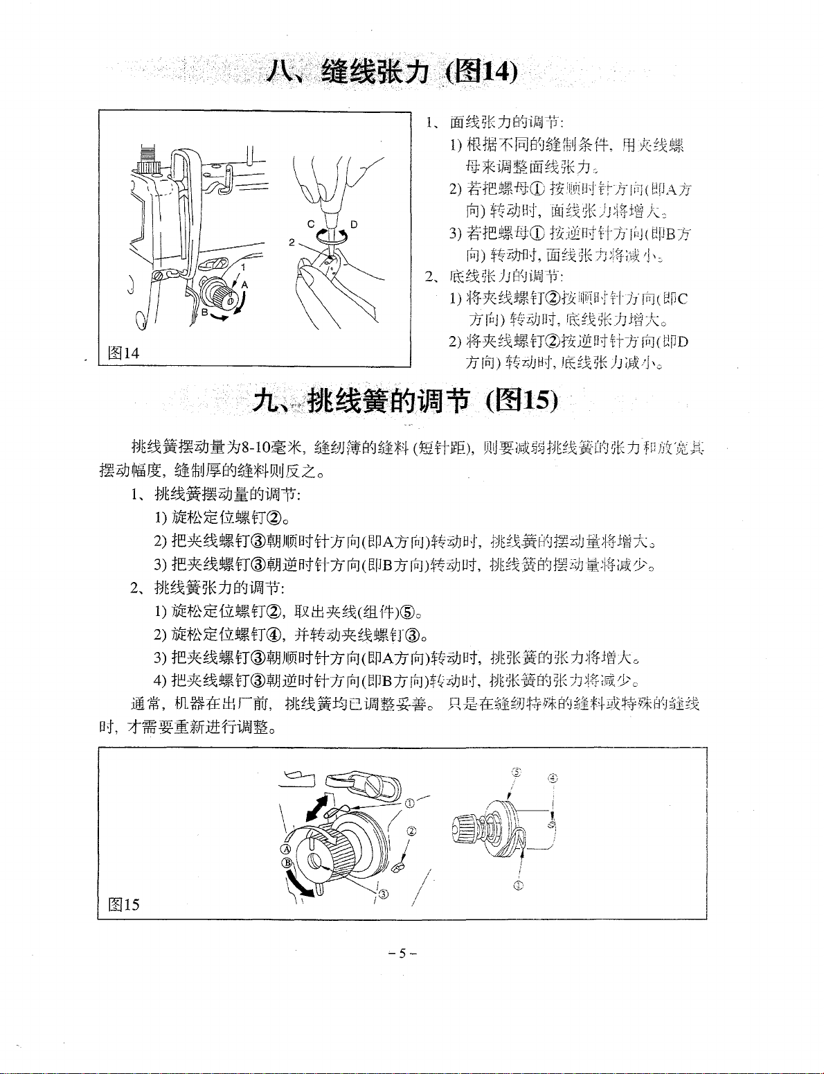
it":
~•~m•~~~~~-~,m~~~:
·~-~~~m*m~,•m~m~,
·~~~ffi~Ntt~,M~~~~~~~~~~o
·~~~oo*~~ffi~*m~~~~ffi~~~,~m~m*mo
•
1iiO
iA It!
tJL
~
~
191
1J
rfiJ
J! N lE
.~m*m~~-~~,mBM~k~~~r~~~~~~~o
liftL
~*~•~-~~~$~~,
*~~~~~mo
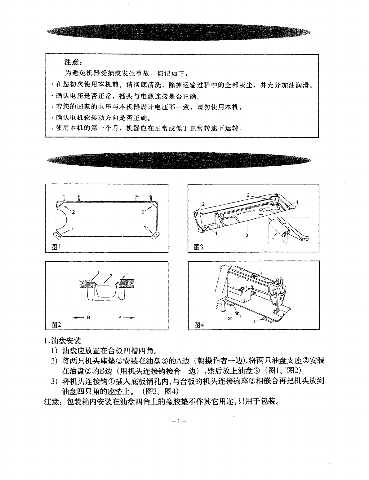
---
B
I.nail~?&
1 )
nailM»t~
2)
~imf{fJLih~mCD~~1±irllll®I¥-JAjft
1£nbil®~B:itl
3)
~fJL~~~t7JCDfmA~tit~:fLI*J,
naillmftjfjf8~~J:o
A~
r±
at&[!!}
111m
1ft
0
(~1*1'F~-Jll.),~Wj~iffiil~~Q)~~
(fflfJL~~~t~~-€1-:lll.)
,~J§iOCJ::ifbtl®
!:§~~l]gfJL~:i!~f~~<J)t§W(-€1flf.1~fJL~~¥U
(~3,
~4)
~~=~~~I*J~~~na~~~J::ag~~~~~~Em~,~mrg~o
-1-
(001,
002)
Page 6
~5
B~
~2.
0~
1..
~JiJ
¥1f
1ffJ
~IJ:
1)
!PJ
¥IE
.ftCDi±AgJig3J
~HIGHic%f§~fj[Ao
2)
~~ruoofE\:~
1JowJTrm
3)
1Jo?ruFo,
i!ilit¥1J
~W
4)
~ r ~iV&B"J1mm$Y~
Low
o
1f~JJ;tJl~,
iJ,
i)lB~
tJUliJ
ic-'% B at,
l2~¥u?mH~~
~IfJ
¥f
1E
$0?7C:k-o
a:~:
2..
~
m
wJT
tfl
~
Et
w-K
~y§
f\Z
B:
fi¥
57\.T$
2ooo--
~*fl
~itt
fr
+
~
t~o
iml
-:p
00
-15~
i!E
_,;_:
1)
$~~}]¥IE;.
aH
t~~
2)
?ru;i~l1tf:f~JjB1JIPJ~~}J,
~JlifJE~aHt~~Bt,
i~-='P
!'l~
1ftna
2500rr
77\.f*
ti
tf:f
CD
PI
_m
o
¥ru.mJ4¥rJ:W£!J\.
fHo
3)
?m.m
i~l1ff:f~JJ
A
1r~fJE~Iffit~~Bt,
c
1JrPJt7~JJ,
*fHo
(1
O%
B
il±I)
fi\lfl}
1ft
o
,g-¥1£1/tim•
11tli-¥}
tJs'-1
l2A
ma-t,
~:k~
T,
~m
·ti
i~
:11
fJE~
~U,~A
l
~u}~
im;.:ii5iiJ.
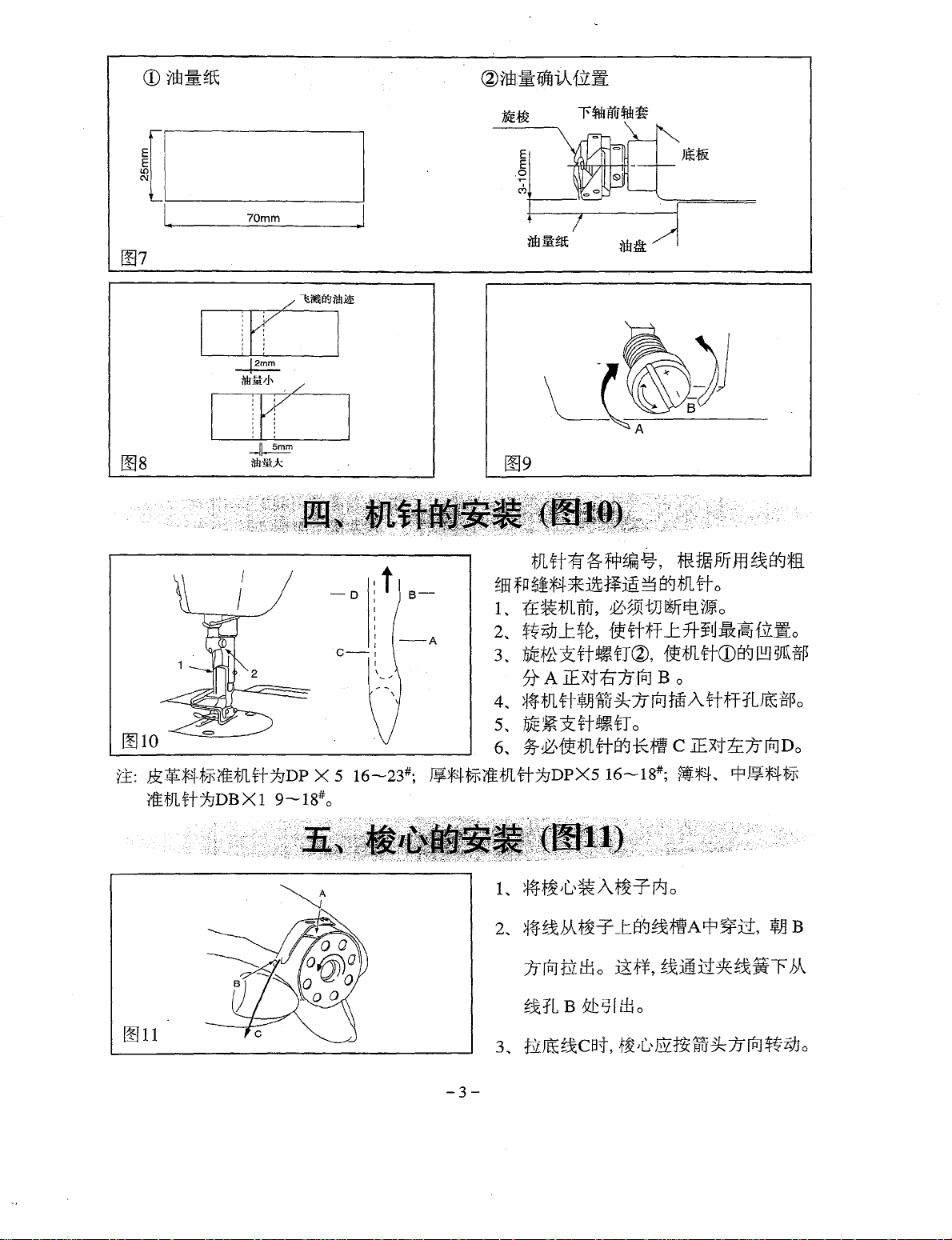
1..
ijtijl)mJ~i~*rw:
1)
*1~fflE!"JtJl-Hf\Z:ittf-rg"J
2)
1mi!}E1:
3)
uflhA
4)
iffi_m1iJ:liABtlflJ~
2,
~_ms"J~m~tffit¥:
1) T !!I
i1$
2)
JtL=J-lE
3
..
i}t]
-=p
1)
~~~
¥Jj-7J(n:JB~#E}JBt,
2)
iJiiJ~Jl5DZJt!:fri"J30f:!/¥/JE!"J~$~,
~,
39!
a
;tJL
iEH
Jl
r-*J
8'-J
iW
t~~t*t~
0
:fj]E
f~
T
$ffi
t~
/G
/Iii
:I:
J1
:J.~
¥li1
_;_g~irt
1ff!Ji:
~IJ$ffi
~
_t
B"J
iEB::I=~~i~j,~o
~~:IE$~
!if
5
1PJ
~
ffl
3
71T$EI"J2:$~
~;It:$
1ti'J
OC
91:
tE
f')9;r:p
(iff
fflf:!;~itB'f)
B~
€JH!iiJ
Iff:~
iJ
r
~:JJ~t~
--=-
iJ\,
i~
1J:JJ!El&
~'ffl
~t~l1
t~
Tfill
HIGH
C~~E!"J®f!~~t~)
Ao
fP
LOW
m
fiJ
pg
o
o
o
:ittfri~
£J~,
TT~J.J
~~1ii§iA~Eit!l~:k0o
§X:iJ8tEI"J
rati:J1$
?m
:i.,
][~
+
1J
rPJ
A!ft~JJ
-2-
~i~
~,
~ir±J
¥5gJit4o
g~_t
rm~
/G
Bt,
1m;_~
fElfY
~3:~
6t±
~
±~*o
/G*i~1JIJ
ft:Jg
Jt.o
~
?m
'-
~{~
0?
_;_
i~-='P
t~
fJ
Page 7
(1~1
1!110
I.
70mm
.I
~Jl
ft
ff
~
f!fl~%,
~m
fP~*4*:i?t1-¥m~
1..
t£
?&~Jl!W,
2,
~i}J_t$~,
3,
~~~rr•rr~,~mrroo~~~~
)J\.
A
4..
*t~Jl
tt
s..
~~xftt~fr
6
..
95-~,f_t~JL#B"J-Kift
~,~Ji
'itff~f
IExtt:J1J(P]
WJiu
~
*
1E
?JT
m
~
tt-J
*ll
s"J~Jl
rr o
t)J
l!ff
~
M o
L:3T~U:&l~EJ{.fl~o
B o
7I
~1m
A.
rrfffL~
o
C
lExtt:c7IIrDDo
ff~o
i.£:
$:1fi;f4~1.FiiE1Jltf:lgDP
X 5 16---23#;
l¥*411.Ff'f:EtJlrr:/9DPX5
iltJltt:/9DB X 1 9---18# o
L
~A
*tt~JL'~At~-Tr*Jo
2
..
~~~~r_t~~~A~~li,~B
1JrtJtlllio
~fL B 5zt~l
1!111
-3-
16--18#;
J!~~,
fif*4
~:imu~~:ii~
t:Bo
..
i=fJ!J*4tl.F
~
Page 8
0012
1..
~i!*-41F§)iJEfH
CDttiti
* 1f
!PJ
$t#JJ,
1JJE
~?JTMi~*
2
..
~m~~~~ft*~ffim~**~o
3
..
*~~~.ffi{~-Koc,
~v
*
1r
!!I
13
-4-
fllo
x1fitJL%1:8"J
rtiJ
ff
T
skJ
1UJ
~~
,8Ao
1Efitl:i!t&-¥~~JJ
s-t,
~~
Li}J
~
;f4
N~
iff:E
Page 9
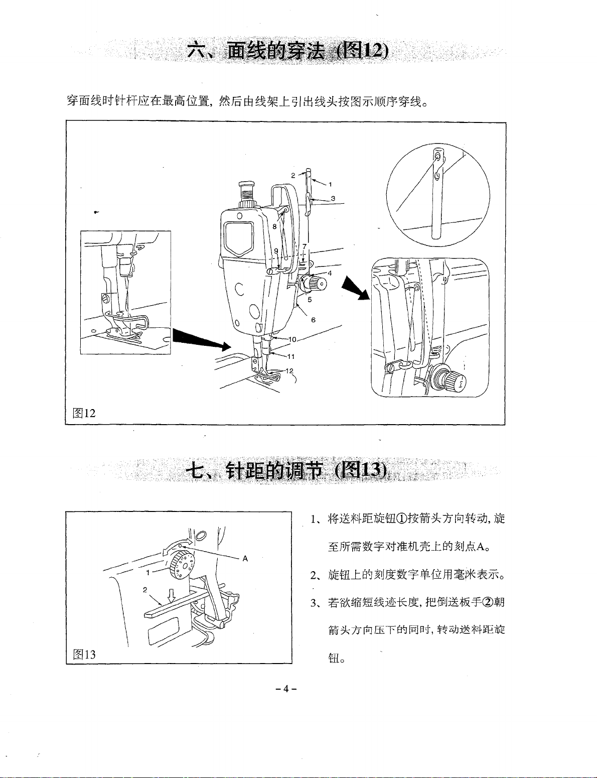
1!114
tiE!x
jim·~}]~
~-Z91
~~It,
1,
2,
~Ji
fjE~:ifmiJJ~8"JiJfiJlt:
1)
1JJE*'t~
2)
tl::
3)
tl::
fjE!x~5iEf78"Ji)ijj1J:
)']
8-1
o~
*·
~Ji!3J
fiju
JJ8'-J~Ji*~
f.fi!t~tJ~o
*!X !ItT
~~jx
t~
D!U
& z o
®¥JJ
}I[Vi
Bt
<ft
tT®~JJ
i2!
Rt
ft
}I
1i
it
rPJ
rtJ
(
(
8~
fii
*-~t-
t!PA1J
t!fJ
B
1J
1..
2_
-.
C
f]Jt
rPJ
)$#i)J B
rtJ
)${r}J Dt,
00
~~
5~
7J
8"Jif~
T.J:
1)
tR
f'*
~
[PJ
B~
~i
ft·IJ
*
f4'
-H}*ifr1J~tm~~5tE1J
2)
~tl::t~-BJ.CD
rP:l)
*~
~)]
'
fi.+-
-:+t-o
rPJ)
-t;;rvJ
rn:
0=:
2~)!
~,\.!:-.X..
J
~-~
J
1)
~*1-~~~~~tJ~fii
1J
rP
j)
2)
~~~~~!il~t1C2J:f:tz]~Bti:t7f
7J
In:!)
$~r)]
lfi=!),
Vl!J
~
;J,
1:3t~~ji
:f?JE~~
t£7J!NH•J:f-!-)i
B•J,
IId
j
--,--
1-l'.'
Uil
a'
{r
i
~1-;+.
:;
v,P.J
lJ
$-~:i)J
Bt,
s~·,
iJ£
~~
:tJt!&
fl'~
*
BJ
::;
g,~
~K
fJ
;j~
±~
1 : •
;1
1/
f •
9,
.
~~
Jt\:
.
HFJ1B't:f-t·:i:i
~(
~:~
Jfff.:~
~:
i~
rJJ
ii
~
:?;)J
;_
jo
7J
~j+j-;ls!(
g-K
)J
1~
5tE
)J
;;Rx
[f~
5-K
::iJ.
~14
±~
j(
;j-ff
1~
j;'
(
~!JAJ-J
Jc::
I
1
.;
\:;
rtJ
(
~rc
1
}::_
c
rPl(~PD
-'J
\c
f P
3~
Jf
o
o
1)
iifE;f!~
JE
fiL!l~
tJ~,
2)
1ifEif'~JE1il!R~<fT@,
3)
1~*
g~!l~
tT®~A
4)
1~1f::
gx9t~
fT@¥JJ
~~,mu~mr~,
B•J,
~Tm~£fJf:i!tfri~~o
~5U±E#j~
#$~i}J1f::!xt~<fT®o
Jllft1Bt
rr1J
i2!
Bt
ft1J
m~•~B~B~*o
1!115
(
g_fiflf
rtJ
(
t!PA1J
rRJ
( epB 1J
)@ o
rRJ
)$~i}J
rPJ
)$!?~}]
I
/·
I
I
'-5-
Bt,
tiE
st(if
8~
51(
iJ
~if±~}(
BJ,
l~t
~K
~
Bl5tz
:h
~4
g~~~m%~~~M~~~~~~
o
;J~
Yo
Page 10
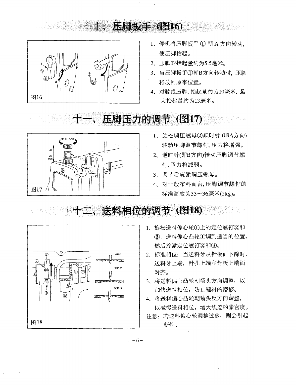
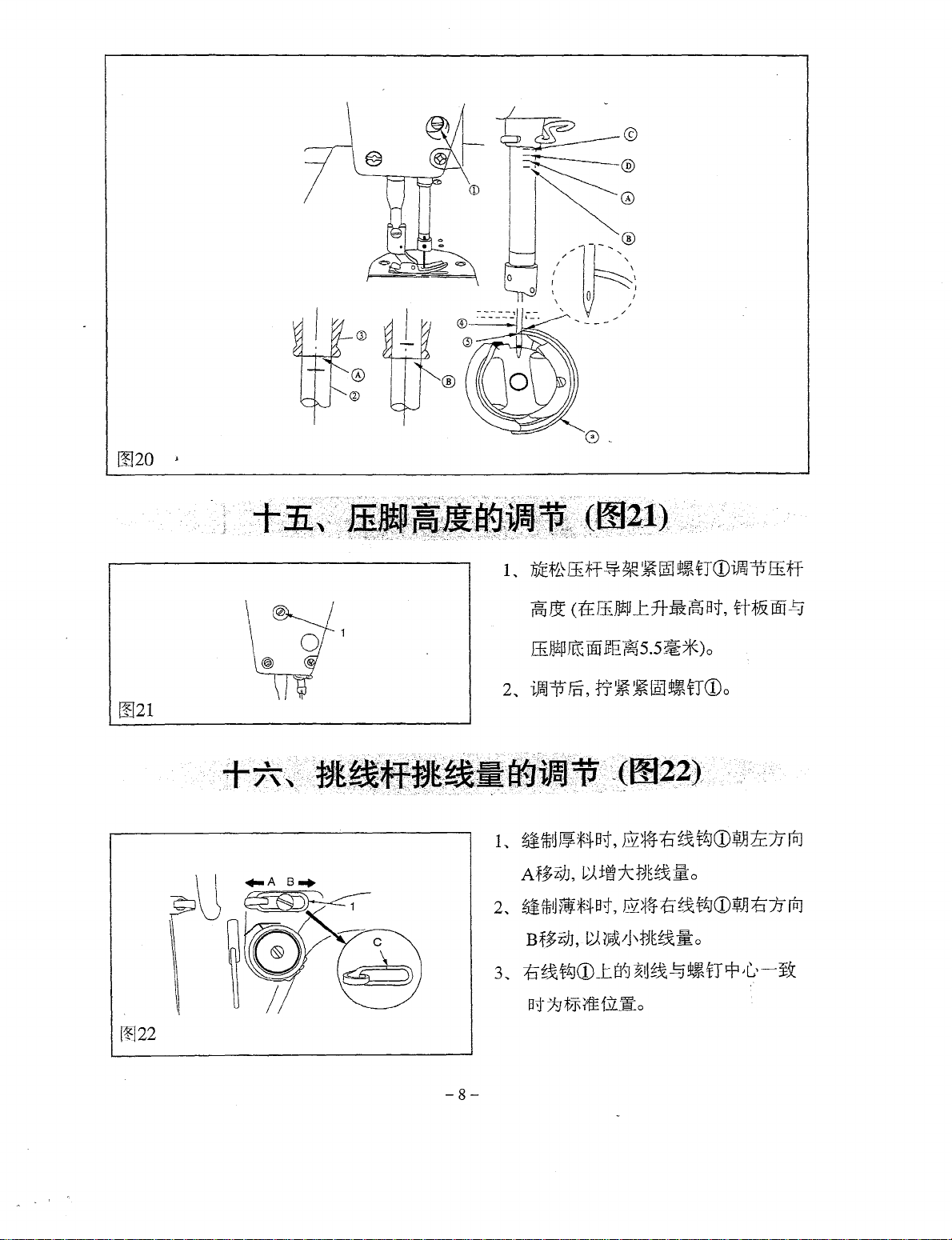
L
f~;fJL~lliE*Pt&-f-
f~
ff
Jjtp
:t~tf
2~
ff)jtps'-J:ttlt.s:S:g"J/95.5~*0
3
~
3
ffijtp
:tJi
~CD:MB
0
CD~
A 7JfR]${i}J,
1J
rPJ
*~i}J
Bt,
lliijtp
1!116
~7Ji@]
4~
x1E*t!ffJj!p,
7ctir~~g'-]7g13~*0
L
2~
3
~
4..
~*fj[~o
1~~£g'-]1]lO~*·
7J~f'tiMJff.t~-BJ:(Z)Jli91Btrr
$~iJJ
fEJ!p
iffiJ
-=p
t~
lfJ,
~Btft(~PB:lJ
fT,
ffJJ~4i~~~o
iffil
·=p
)f§-
J]JE
xt
---
f.N
1!J
;fJF{fE~
~/933-36~*(5kg)o
rPJ)t#i}J
~
i,ffl]
ff
~-t
rm ~ ,
.t~
ff
(~~AlJrPJ)
ff
n
~
ff)jtpiffiJl1
-B}
0
JP
iftH
-=p
~
±~B!a
o
t~
t~
fi
s"J
~18
~
mrflf'.
-6-
L
71JEt~*r4fi{.-$t:CDI.s~5Ef.flt~fT(Z)fiJ
@,
**41i
f~
f6
rr
2~
;fffiilt§fJ[:
j~)fE4
~
JL"
~;t
f3lt"
3~*4~
_tizf/lj,
8
$tCDi.fflJ¥Vm
fJ~
fiJ
®o
b\rrf&OO~~~Bt,
rr
iLJ:ftfM-
fll
ftt&__I:
3
8~
1.fr.Ii,
ftfM-
W
x'.!Jfo
3
~
~~~f4fA~H~."
1JoH~~*4tEI{~,
4~
~4~;f4fiJL"u~~JJf.i~&7JrPJiffiJ~,
~~~*#~~'
r.±~:
~**41ffia{,,.*:iJ~~tt~,
8
$~.!f!Jlfri
~
1J
rPJ
iffiJ
~,
~
~JJJ.C~r41¥Jti~o
·
m*~~~~~~o
mu~i71,g
®fffo
Page 11
1!119
1.
~-#.
if&~
7fEtttrrif&~tB
~*4B;f,
2.
~I:J*:i!*4
~~ifc~*4~~0
3,
b
iJ~j"=p~~+7f~Jto
1)
t~f'£tit
2)
L.
3)
]"JE~ffEfP§!t~'fJ@o
~#*#~~~-~~*
tB
1.15-1.25 mmo
0.8-0.9
;lt~tfj~jJ0.7-0.8mmo
7fjj:5J\.8
7f
)l3f~
B±l
~f$E}J3f~m1-T~-='fi
~J¥*4-~*4
mm,
rmgil
ttl,
1£ti¥f*4Bt,
til§
CD
8'-J
~liD\~
tT~
o
o
8:~:
*r±Bt~~~lfJ~~ffi}J:*;J\
1)
${E}J_t$~,
2)
1iJH~rrift~oc=
a,
~
ttXE:1ilt~fTCDo
b,
f!i!fflDAftBt,
tt~
3)
1i~iE:h"JEt.&filii:
a.
{~Jt!DB<ftBt,
ffT$ffi~@B"J~tz#&o
b,
ftfflDAttBt,
1tTtfffil-T:S:fE£i~C
fflDB
ftBt' 1t trff@
~Ttiff@_ts{]~Jj~Cxtitftiffr$~@1¥JTftfffi,
f1rt"
TJCD
o
JJJEt'£-=Q:h"JEt.&~fil!t"fJ,
__
t
I¥J
JJJEta=_RhfEt.&/E11r\"<fJ,
~~ti:J?tJZJf~r±Bt~~mo
WnJEf'£TtiffJ!~tt/Efilt"<fTCDo
~tl
~Axt
it
rrff
T$E8~@1¥J
fr~E}J_t~,
#-$tE}J_L$£,
Tftfffi'
~ftiff@_t1¥J~tl~Bxtii<ft
{~Jtff@_tB"J~tl~Dxtfiftiff
?.t
1§-:h"JE~
f.~J§":h"}E~ftiffi!~
rriff~~
T$ffi~@B"JT~o
4)
t£_t:i£~7t
r.t
!§"
1±~:
a.7Efi'SJ
b.JJJEt.&JJR*m
1$
T,
1tJJJE1.&
rr
~tJEt~
~
!);'itf~;J\,
8'~
i9
~
~ID
t~
fT
o
~~19H.&~;
ft~W.-¥5-,
i~1~€,
~®
xt
7Efi'SJ
t''l
tJl
tt@
I¥J
~,
L.
~
!);~x*,
i~1tm
~51~1f3~ft
}Jjl*s'-1~%
-7-
Jt
_!:;]
o
o
JJJEt~
8"J
I'SJ
WJ.:
~o.
04-o .1
mm,
Page 12
0020 j
[!121
1.
~*ffi~~~~~•noo~~ffiff
~
oc
ctr
I±JJtP
.r.
rt-:&i
~at
rr~&
rnr
13
ffil1tP
ffi:
00
lEP-
~
5.5
~*)
o
2.
iJJ-='P€,
1.
~1ffuJI~t¥4Bt,
fr~~~t~iTCDo
~~tl~iiJCD¥Jt6:7JrtJ
Af_~i}],
2.
~Ji
1tU
¥i
~4
Bf$i')J,
3.
:tl~itJ(D_t~~tl~!3t~iT*'L.'-i~
Bt
1J
1/F
~22
-8-
~jf~jc~~~:;:o
Bt,
B~DI-ft
tl
~
ft)00¥)j
~t'~IJ\ME~£o
f~
fJLAo
:tl1J
rPJ
Page 13
47
63.5 8
75.5
1!]23
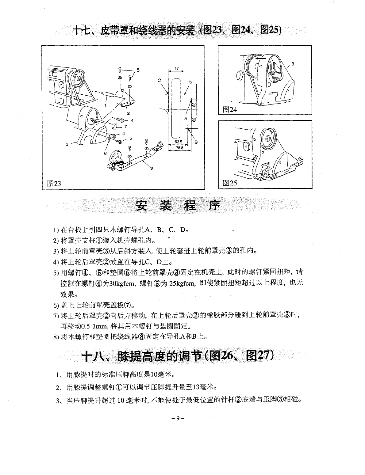
1)
T±Ei't&.L
2)
~1J%3Et±CD~AtJL%t~iLI*Jo
3)
~
_t$~1W~'ie@JAJ§-~~1J~A,
J71!21LR*!l!Jt~fT~1LA
..
B
.. C ..
Do
{9!_t$~~:ttt_t~fltr1l%@s~fLr*Jo
0024
4)
~
_t~J§-
5)
mt~fT®
1~*u1±t~fT@~30kgfcm,
~'if:@J]~ifif~tLC..
..
@fQf11:~@~~
.L$£1frJ.$7C®IAI1Eif~JL%_t,
n_to
t~aT@)g
25kgfcm,
~Pf~~riDt.H~f:i:~tLi:i~.Lf.¥&,
~~*0
6)
~_t_t~WJ~'ie~f,&(1)o
7)
~if
_t$~!§-~~~~
1Pf~E}J0.5-1mm,
8)
~*t~fTfPf11:~t~~~t3%H®m!~
1..
ffl
n*ti:Bt8~f~ilffil3!P
2..
ffl
n*mi~~t~fTCDPJ
3..
~
ffijj!p~ff-!11Li:iiO
f6"1Jf~E)J,
*tJtffl*t~fT~m!m!ID~o
tf_t_$£J§"~'ie®B"J~~{f~]J\.i~ftl_tJ~§tr~'iC@Bt,
tE.!$fLAfPBl:o
tsJ
J.lJ'f!::
10~*o
~~
ifflJ-='P
ffi,ljtPt~ff-
~*Bt,
7f~fi~{t~~-f!lf~{Jiit8~rrff@J"€fitffit!3
_;_E~J3~*o
-9-
ttats~t~fT~Iillt.H~EI,
i~
i:E.x
ffiJ]tl1@1§1i]to
Page 14

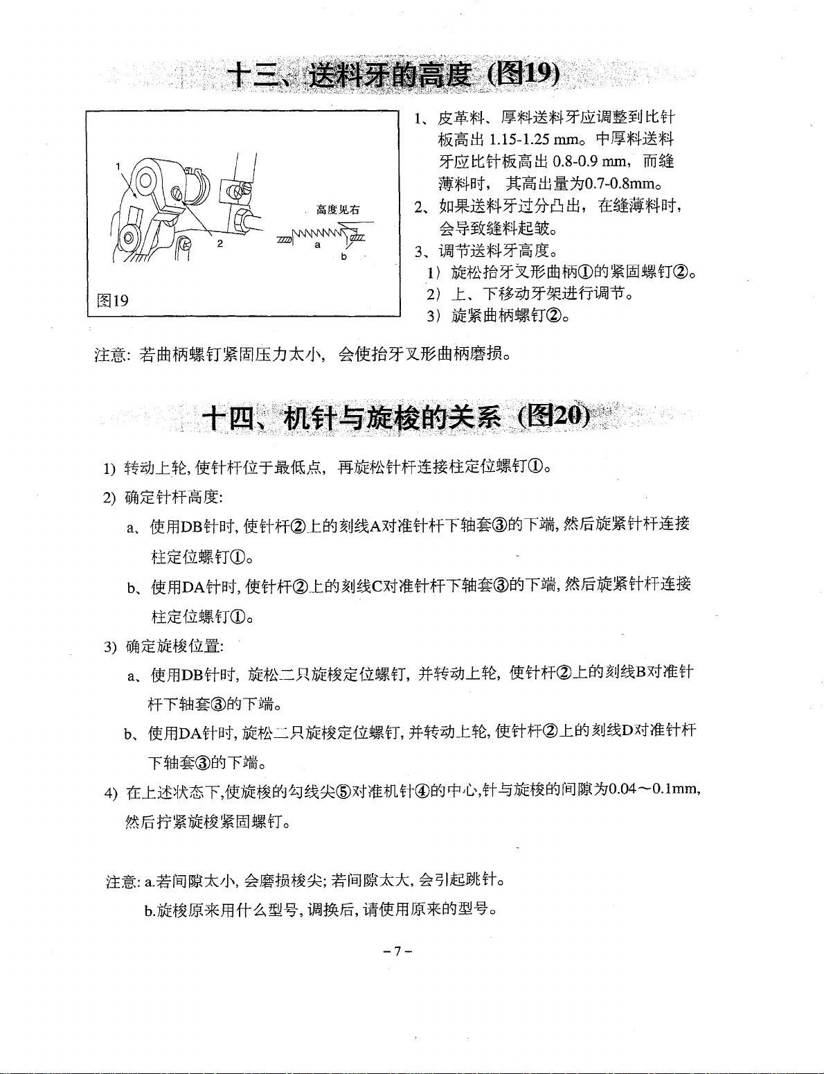
~i*4
~f-~L
~~*4
[!!27
~
*~
..
~1¥*4
~r~g]i)f
~*f·t-IEE
ffi]tPi=Jt
fh~
oc < -¥m)
CH*t~)
-tfltt
~1fJ¥f.tnb
~AJlr}J~~
i±:
L
~f4~~JJBtfm~t~ll]tP,
2..
ff.IJ*P1Ji~$~83Jjipm~:r±~ru!-~
5500~tJ)J\.
5rnm
6mm(il*)
13mm(il*)
DBXl
9#--18#
lftif&,
I
z;f47f#-f'Fm~B~iml~o
51JORo
3ooo~t-!-ln\.
8mm
6mm(~:k)
13mm(il*)
DPX5
16#--18#
-
3000!tti)J\.
8mm
8mm(il:k)
13mm(~*)
DPXS
1o%a¥m
370W
20#--23#
~fi~~-~~-~~~-~~~~m•~~m•••,
~~~l=~fr~~*ilffl
i}ta~
~
I*J~~I!ii~
F
~£trrrmmJ2Z~S£o
-10-
Page 15
INSTRUCTION MANUAL
To
get the most out
to use this machine correctly.
Please read this Instruction Manual carefully before use. Whe hope you wi!l enjoy the use
your machine for a long time.
Please remember to keep this manual
1.
Observe the basic safety measures, including, but not limited to the following ones, whenever
you use the machine.
2.
Read all the instructions, including, but not limited to this Instruction Manual before you
use the machine ,
anytime when necessary.
3.
Use the machine after it has been ascertained that it conforms with safety rules/standards
in
valid
4.
All safety devices must be
The operation without the specified safety devices is not allowed.
5.
This machine shall be operated by appropriately-trained operators.
6.
For your personal protection, we recommend that you wear safety glasses.
7.
For the following, turn off the power switch
the receptacle.
7-1
7-2 For replacing part(s)
7-3 For repair work,
7-4 When leaving the working place
8.
If you should allow oil, grease,
with your eyes or skin or swallow any
contacted areas and consult a medical doctor.
your country.
For threading needle(s) and replacing bobbin.
of
the many functions
In
addition, keep this Instruction Manual so that you may read it at
in
position when the machine is ready for work or
of
needle, presser foot, throat plate, feed dog, cloth guide etc.
of
this machine and operate it
in
a safe place.
of
disconnect the power plug
of
when the working place
etG.
used with the machine and devices to come
of
such liquid by mistake, immediately wash the
is
in
unattended.
safety, it is necessary
of
the machine from
in
operation.
in
contact
of
9.
Tampering with the live parts and devices. regardless
is prohibited.
10.
Repairing, remodeling and adjustment works must only be done by appropriately trained
technicians or specially skilled personnel.
11.
General maintenance
12.
Repair and maintenance works
electric technicians or under the audit and guidance
Whenever you find a failure
13.
Periodically clean the machine throughout the period
and
inspection works
of
any
have
to
of
electrical components shall be conducted by qualified
of
electrical components, immediately stop the machine.
of
whether the machine
be
done by appropriately trained personnel.
of
specially skilled personnel.
of
use.
-11-
is
powered,
Page 16
14.
Grounding
machine has to be operated
as high-frequency welder.
15.
An appropriate power plug has to be attached to the machine
plug has to be connected to a grounded receptacle.
16.
The machine is only allowed to be used for the purpose intended. Other used are not allowed.
17.
Remodel or modify the machine
all the effective safety measures. We assumes no responsibility for damage caused by
remodeling
18.
Warning hints are marked with the two shown symbols.
the.
machine is always necessary
in
an enviorment that is free from strong noise sources such
in
or
modification
of
the machine.
of
Danger
Items requiring special attention
injury to operator or service staff
tot
the normaloperation
bY
electric technicians, Power
accordance with the safety rules/standards while taking
of
the machine. The
-12-
Page 17
FOR
1.
To
avoid electrical shock hazards, neither open the cover
for the motor nor touch the components mounted inside the electrical box.
1.To avoid personal injury, never operate the machine ·with any
cover, finger guard
2.To prevent possible personal injuries caused by being caught
your fingers, head and clothes away from the handwheel, V belt and the motor
while the machine is operation.
3.To avoid personal injury, never put your hand under the needle when you turn
"ON"the power switch or operate the machine.
4.To avoid personal injury, never put your fingers into the thread take-up cover
while the machine is
5.The hook rotates at a high speed while the machine is in operation.
possible injury to hands, be sure to keep your hands away from the vicinity
the hook during operation.
machine when replacing the bobbin.
6.
To
avoid possible personal injuries, be careful not
machine when tiling/raising the machine head.
7.
To
avoid possible accidents because of abrupt start
the power to the machine when tilting the machine head
cover and the V belt.
8.1f
your machine
while the machine is at rest.
noise
of
start
9.To
the machine, be sure
avoid electrical shock hazards, never operate the sewing machine with
SAFE.
of
safety davices removed.
in
operation.
is
equipped with a servo-motor,the motor does not produce
OPERATION
of
the electrical box
of
in
the machine.
In
addition, place nothing around them.
To
In
addition, be sure to turn OFF the power to the
to
allow your fingers
of
the machine, turn OFF
or
removing the belt
To
avoid possible accidents due to abrupt
to
turn OFF the power to the machine.
the belt
keep
prevent
of
in
the
the ground wire for the power supply removed.
10.To prevent possible accidents because
component(s),turn
on
of
the power plug.
OFF the power switch
of
electric shock or damaged electrical
in
prior-to the connectrion/disconnecti
-13-
Page 18

CONTENTS
BEFORE
1.
INSTALLATION·················································································15
2.
LUBRICATION··················································· ...
3.
ADJUSTING
4.
ATTACHING
5.
SETTING
6.
THREADING
7.
AqJUSTING
8.
THREAD
9.THREAD
10.
HAND
OPERATION·····································································
-.
..
·····················
THE
AMOUNT
THE
NEEDLE·······························································
THE
BOBBIN
THE
MACHINE
THE
STITCH LENGTH······································· ···············1 9
THENSION··· ··· ··· ··· ··· ··· ··· ··· ··· ··· ··· ··· ··· ··· ··· ··· ··· ··· ··· ··· ··· ··· ··· ···20
TAKE-UP
LIFTER···········································································
SPRING·····························································
OF
OIL
COIL
SPRASHES)
INTO
THE
BOBBIN
HEAD···················································
CASE······························
IN
THE
HOOK······16
····15
···16
···18
···18
···1 9
···20
···21
11.
PRESSER FOOT
12. ADJUSTING THE FEED
13.
HEIGHT
14. NEEDLE-TO-HOOK
15. ADJUSTING
16. ADJUSTING
17.
INSTALLING
18. ADJUSTING
SPECIFICATIONS·····························································~·······
19.
OF
PRESSURE······················································
TIMING···················································
THE
THE
THE
THE
THE
FEED
HEIGHT
THREAD
BELT
HEIGHT
DOG·······················································
RELATIONSHIP·············································
OF
THE
TAKE-UP
COVER
OF
THE
PRESSER
STROKE······························
AND
THE
KNEE
FOOT·····················
BOBBIN
LIFTER· ..
WINDER············ ···23
························
···21
···21
···22
···22
···23
···23
... 24
···25
-14-
Page 19

I Attention required before operation
Attention:
To
avoid machine damaging
1.before using the machine for the first time,
the dust and make sufficient lubrication.
2.make sure that the voltage is right,and that plug and power source are correctly
connected.
3.if the voltage in your country
do not use
4
..
make sure the running direction
5.during the first month when using this machine, you
speed
it.
or
lower speed.
or
some accident, please do remember:
please clean it thoroughly, get
is
different from the voltage
of
the motor ,wheel is right.
of
this machine,please
should run it
rid
in
the normal
of
all
Fixing
Fig.1
Fig.2
1.fixing
1) oil tray should be put
2) Fix two arm cushion"1 "to the"A"side
Fix the
fix the
3)
Plug the hinge"1 "into hole
plate,
of
attention:in
of
oil
---
oil
the
tray
of
the machine
B
A~
tray
at
the
four
two
stand bases"2"to the"B"side
oil tray"3''(picture1 ,picture2)
of
bed plate,put the machine head on the table
hinge
four
is
at
the sink place and then fix the machine head on cushions
oil tray corners(picture3,picture4
the
packing
not
for
any
box
other
,the
usage,just
corners
of
rubber
Fig.3
Fig.4
~~--------------------~
of
the slot in table plate.
oil
tray"~"(facing
of
oil tray"3"(hinge side ),then
).
cushions
for
packaging.
fixed
the operator).
at
the
four
corner
-15-
Page 20

12.
LUBRICATION
(Fig,5,6)
A WARNING:
~
Turn OFF the power before
work so as to prevent accidents caused
by abrupt start to the sewing machine.
1.1nformation on lubrication
1)
Fill oil pan
white oil) up to HIGH mark A.
2)
When the oil level lowers below LOW mark
refill the oil pan with the specified oil.
3)
When
you
window®
4) Note that the amount
unrelated to the amount
(Precaution) When
WARNING:
CD
with sewing-machine oii(No.1 0
you
operate the machine after lubrication,
will see splashing oil through oil singht
if the lubrication is adequate.
of
of
you
first operate your machine
or
after setup
period
at
about
of
of
2,000 s.p.m.
10 minuter for the purpose
break-in.
after an extended
disuse, run yout machine
st~rting
the splashing oil is
the lubricating oil.
To
2,500 s.p.m for
A Turn OFF tne power before starting the
~
work so as to prevent accidents caused
by abrupt start to the sewing machine.
the
B,
Fig. 6
13.
ADJUSTING
. 2.Adjusting the amount
plate parts.
1) Adjust the amount
take-up and needle bar crank
adjust pin
2) The minimum amount
marker dot A is brought close to needle bar
crank®
3) The maximum amount
marker dot A is brought to the position just
opposite from the needle bar crank by turning
the adjust pin
THE
AMOUNT
WARNING:
Be extremely careful about the operation of the machine since the amount
be checked by turning the hook at a high speed.
OF
OIL
(OIL
-16-
SPLASHES
CD
.
by turning the adjust pin
in
of
oil supplied to the face
of
oil supplied to the thread
of
oil is
of
oil is reached when
direction
IN
THE
C.
HOOK(Fig,7.8.9) I
® by turning
reac~ed
of
when
in
drection
oil has to
B.
Page 21

(,'
I '
~·'\..,
r-
...
..
'
u
(!)Amount
Fig. 7
*When carrying out the procedure described below
extreme caution not to a allow your fingers to come
(Cautions
2) Place the amount
machine is in operation
3) Confirm that the height
"HIGH" and "LOW".
4) Confirmation
of
esample
of
oil {oil splashes) confirmation paper
tl
1!-----------.1
70mm
• Use any paper available regardless
1)
If
the machine has not been sufficiently warmed up for operation, make the machine
run idle for approximately three minutes. (Moderate intermittent operation)
of
oil (oil splashes) confirmation paper under the hook while the sewing
of
the amount
time with a watch)
showing the appropriate amount
I
.I
of
the material.
of
the oil surface
of
oil should
Splashes of from the hook
[/
I approx.2mm
Appropriate amount of
I 1[/
--JI
F"
1
L...-_
_9_·
8-----------------~
eAdjusting
hook bushing
Fig. 9
Appropriate amount of oil (large)
the amount
oil (srnall)
Splashes
of
oil from the hook
:pprox.Smm
of
oil (oil splashes) in the mounted on the hook driving shaft front
®Position to confirm the amount
_
Oil splashes confimrmation paper
Closely
• Place the amount
the hook.
in
contact with the hook.
in
the oil reservoir
be
completed in five seconds.(Check the period
of
oil
1) The amount
the left should
with sewing processec. Be careful not to
excessiveiy increase/decrease the amount
oil
the hook will be seized (the hook will be hot).
If
product may be stained with
2) Adjust the amount
the
change while checking the oil amount three
times
1) Turning the oil amount adjustment screw
will increase the amount
in
B)
2) After the amount
properly adjusted with the oil amount adjustment screw, make the sewing machine run
idle fot approximately
the amount
of
oil( oil splashes)
Hook driving shaft front bushing
___..:.H::.:OO;:_k
--..
Oil reservoir
fit
the paper against the wall surface
of
oil (oil splashes) confirmation paper under
in
2), remove the slide plate and take
i~
within the range between
of
oil shown is the samples on
be
finely adjusted
in
the hook.(lf the amount
the amount
oil amount (oil splashes) should not
(on the three sheets
the hook,
will decrease it.
of
oil is too much, the sewing
in
the "+" direction (in direction A)
or
in
the"-"
of
oil in the hook has been
of
oil (oil splashes) in the hook.
of
the oil reservoir.
in
accordance
of
oil is too small,
oil.)
of
oil
in
the hook so that
of
paper).
of
oil (oil splashes)
direction (in direction
30 seconds to check
of
-17-
Page 22

14.
ATTACHING
Fig. 10
THE
NEEDLE
-o
c-Q:
(Fig.1
-A
\
\
0)
I
Follow the procedure described below to attach
the needle, after confirming that the motor has
come to a complete stop.
A needle
proper needle size according to the count
thread and the type
1) Turn the handwheel until the needle bar
2) Loosen screw ® , and hold needle
3) Insert the needle fully into the hole in the
4) Securely tighten
5) Check that long groove C
1.Notes: The standard needle for leather is
Another standard needle for heavy material
5
light material is
WARNING:
A Turn OFF the power before starting the
~
work so as to prevent accidents caused
by abrupt start to the
of
DP x 5 should be used, Select a
of
reaches the highest point
indented part A facing exactly to the right in
direction
needle bar
the end
facing exactly to
08*5
is
DB*5(16-18#}the
B.
in
of
hole is reached.
(16-23#);
08*1
the dirction
screw®.
the
standard needle for
(9-18#)
sewinQ machine.
material used.
of
its stroke.
of
the arrow until
of
tHe
left in direction
CD
with its
needle is
D.
of
is.
SETTING
Fig.
11
THE
BOBBIN
A
INTO
THE
BOBBIN
1) Install the bobbin
2) Pass the thread through thread slit A, and pull
3) Check that the bobbin rotates
-18-
CASE
the thread wound direction is counterclockwise.
the thread
thread
come out from notch
of
the arrow when thread
(Fig.11}
in
the bobbin case so that
in
direction
will pass under the tension
B.
By so qoing, the
B.
in
Cis
pulled.
the direction
~pring
and
Page 23

js.
THREADING
THE
MACHINE
HEAD(Fig.12)
-
The needle bar should be the highest, Then draw a thread end from the thread holder and thread
follows:
it as
Fig.12
j1.
ADJUSTING
Fig.13
THE
STITCH
LENGTH
-19-
(FIG.13)
1) Turn stitch
arrow, and
A on the machine arm.
2) The
3) When you want to decrease the stitch length, turn
dial calibration is in millimeters.
stitch length dial
in
the direction
length dial
align the desired number to marker dot
of
CD
in
the direction
CD
while pressing feed lever ®
the arrow.
of
the
Page 24

Is.
THREAD
Fig.14
19.
THREAD
TENSION
TAKE-UP.
(Fig.14)
SPRING
(Fig.15)
1.Adjusting the needle thread tension
1)
Adjust
the
needle thread tension using tension
adjust nut
specifications.
2) As you turn nut
the needle thread tension
3) As you turn nut
direction B), the tension will decrease.
2.Adjusting the bobbin thread tension
1)
As
you
(in
direction C), the bobbin thread tension will
increase.
2) As you turn
Direction
decrease.
CD
according to the sewing
CD
clockwise (in direction A).
will increase.
CD
counterclockwise
turn tension adjust screw ® clockwise
screw®
D),
the bobbin thread tension will
counterclockwise (in
(in
® direction B), the stroke will be decreased.
I
I
CD
Fig.15
1.
The width of take-up spring is
sewing material
width),
and wide the sway of
opposition.
2.Changing the srtoke
pis lighten the take-up spring tension . .
.
is
thin material (short needle .
it. Otherwise, pis do to :
of
thread take-up spring
8-1
Omm.
if the
CD.
1 ) Loosen set screw ® .
2) As you turn tension post @ clockwise (in
of
sirection A), the stroke
spring
will
be
increased.
the thread take-up
3) As you turn the knob counterclockwise
3.
Changing the pressure of thead take-up
spring
1) Loosen set screw ® , and remove thread
2) Loosen set
3)
4) As you turn the post counterc ockwise
4.Ususlly, upon the machme commg
CD.
tension
As
direction A), the pressure will
direction B), the pressure WI e decreased.
take-up spring has been adjusted
while sew special material or special thread,
it need to
CD.
screw@.
you turn tension post @ clockwise
be
increased.
1
b
11
~t.
well, Only
be
adjusted again.
(in
(in
(
in
all the
-20-
Page 25

11
0.
HAND
Fig.16
LIFTER
(Fig.16)
1)
To
stop the machine with its presser foot up,
turn hand lifter lever
2) The presser foot will go up about 5.5mm and
stop.
The presser foot will go back to its original
position when hand lifter lever is turned down
in
direction
3) Using the knee lifter, you can get the standard
presser foot lift
maximum lift
B.
of
CD
in
direction A .
of
about 1
about 13mm.
Omm
and a
111.
PRESSER
FOOT
PRESSURE(Fig.17)
I
A Turn OFF the power before starting the
~
1) Loosen nut
regulator
presser foot pressure will be increased.
2) As you turn the presser spring regulator
counterclock-wise
will be decreased.
3) After adjustment, tighten
4) For general fabrics, the standard height
presser spring regulator is 33 to
A Turn OFF the power before starting the
~work
12.ADJUSTING
. . cam
1
Fig.18
THE
FEED
TIMING
(Standard feed timing)
_ J [ Needle Needle
~plate
( (Advanced feed timing)
?222ai""""""""4
(Fig.1S)
~
I222Z
I 1) Loosen
2) For the standard adjustment, adjust so that the
3)
@or=+::
4)
5)
direction
the arrow, and firmly tighten the screws.
top surface
needle eyelet are flush with the top surface
throat plate when the feed dog descends below
the throat plate.
To
uneven material feed, move the feed eccentric
cam
To
stitch tightness, move the feed eccentric cam
in
the opposite direction from the arrow.
if
feed eccentric cam adjust too much, it will
cause the broken
WARNING:
work so as to prevent accidents caused
by abrupt start
® . As you turn presser spring
CD
WARNING:
so as to prevent accidents· caused
by abrupt start to the sewing machine.
screws_
CD
. Move the feed eccentric cam
of
the arrow or opposite direction
of
advance the feed timing
in
the direction
delay the feed timing
of
the sewing machine.
clockwise (in direction A), the
(in
direction B), the pressure
nut®.
36mm
® and ®
feed dog and the top end
of
of
needle.
in
in
order to prevent
the arrow.
in
order to increase
feed eccentric
(5
of
in
the
kg).
the
of
of
of
-21-
Page 26

113.
HEIGHT
OF
THE
FEED
DOG(FIG.19)
Height: Please refer to the right
I
CAUTION:
Be
careful not
cam
too
result.
WARNING:
to
move
the
far,
or else needle breakage
feed
eccentric
A Turn OFF the power before starting the
~
work so as to prevent accidents caused
by abrupt start of the sewing machine.
may
Ym~
b
Fig.19
114.NEEDLE-TO-HOOK
WARNING:
A Turn OFF the power before starting the
~
work so as to prevent accidents caused
by abrupt start to the sewing machine.
1.Adjust
the
1) Turn the handwheel to bright the needle bar
down to the lowest point
loosen set screw
(Adjusting the needle bar height)
2) Locate the needle height
a. while using
the bottom end
then
the
timing
hook
as
follows.
DB
tig~!en
set screw 1 .
RELATIONSHIP
between
CD
.
needle, aligh marker line A with
of
needle bar lower bushing
the
of
{Fig.20)
needle and
its stroke, and
I
3,
1) The feed dog is factory-adjusted so that it just
out from the throat plate surface 1.15mm to
1.25 mm.
To
adjust the height
2)
CD
Loosen screw ®
® Move the feed bar up
adjustment.
@ Securely tighten screw ® .
(Caution)
insufficient,
a,
Feed dog
3). The feed dog for leather heavy material
must be adjusted 1.15-1.25mm higher than
needle plate. The feed dog for mid-heavy
material must be
needle plate, while sew thin material, the
suitable height is
b.
While using DA needle, align mark lfhe C with
the bottom end
then tighten set screw
3) Locate the hook position.
a.
While using DB needle, loosen the two hook
set
line B
end
b.
While using DA needle, loosen the two hook
set
screw,
line D
end of needle bar lower bushing
4) After making the adjustments mentioned in
the above steps, align hook blade point
with the center
clearance
value) between the needle and the hook, then
securely tighten setscrews
(Caution)
2.
Use a hook
replacing your hook with a new one.
-22-
If
the
b.
Needle plate
screws,
turn
on
ascending needle bar 2
of
needle bar lower bushing 3.
turn
on
asending needle bar 2 with the bottom
of
1.
If the clearance
pornt
smaller than the specified value, the
blade point
If
the clearance is larger, stitch
skip-ping will result.
of
the feed dog:
of
crank
CD
.
of
down to make
the
clamping
forked
the
the
0.06mm to 0.15mm (reference
portion
0.8-0.9 mm higher than
0.7-0.Bmm.
of
needle bar lower bushing
1.
hand
wheel,
hand
wheel,
of
needle @ . Provide a
or
hooK
of
of
the same part No. when
pressure
will
wear
and
align market
with
the
and
align marker
3.
in
the hoqk.
betwe@n
and
hook will be damaged.
t11e
the
needfe
is
out.
3,
bottom
@
blad.e
1s
Page 27

l1s.
ADJUSTING
Fig.21
116.
ADJUSTING
THE
THE
HEIGHT
THREAD
OF
THE
TAKE-UP
PRESSER
FOOT
WARNING:
(Fig.21)
A Turn OFF the power before starting the
~
work so as to prevent accidents caused
of
by abrupt start
1) Loosen setscrew
foot height and the angle
2) After adjustment, securely tighten the set screw
the sewing machine.
CD
. And adjust the presser
of
the presser foot.
CD.
STROKE(Fig.2~}
WARNING:
A Turn OFF the power before starting the
~
work so as to prevent accidents caused
' by abrupt start
1 )When sewing heavy-weight materials, move
thread guide
increase the length
the thread take-up.
2) When sewing light-weight materials, move
thread guide
to decrease the length
the thread take-up.
Normally, thread guide
3)
way
that marker line C is aligned with the
center
of
the screw.
of
the sewing machine.
CD
to the left in direction A to
of
thread pulled out by
CD
to the right
of
CD
in
direction B
thread pulled out by
is positioned
in
a
117.
INSTALLING
Fig.23
THE
BELT
COVER
47
AND
THE
BOBBIN
1.1nstallation
1) Drill four guiding holes
wooden screws in the table.
Install. belt cover support
2)
hole in arm.
3) Pass the handwheel through the hole
cover
arm. At this time, you can
the handwheel diagonally from the rear
handwheel by tilting belt cover A
illustrated in the figure.
4) Place belt cover B ® on guiding holes C
and
5)
@ , @ and washer ® ,
screw
-23-
A ® , then set the handwheel on the
D.
Fix
belt
@ with a tightening torque
WINDER(Fig.23,24,25)
procedure
A,
CD
smo~thly
cover
-A @ on
the
arm
At
this time, tighten
B,
in the tapped
C and D for
in
belt
install
of
the
® as
using
screws
of
Page 28

Fig.24
Fig.25
l1s.
ADJUSTING
Fig.26
THE
HEIGHT
OF
THE
of
30 kgf/cm and screw @ with a tightening
torque of 25 kgf/cm.
screws, the securing state
not change.
6) Fit cat
7) Move belt cover B ® backward E until the
8) Fix bobbin winder
Warnings: 1) For safty's needs, belt cover
KNEE
(J)
to the belt cove
rubber section
contact with belt cover
move the belt cover B in the
by
0.5 to 1 mm. Now, fix the belt cover B
in
position using wooden screw and washer.
and B using wooden screws and washers.
2) The left and right parts
LIFTER
WARNING:
(Fig.26,27)
If you tighten further these
of
the belt cover will
A.
of
belt cover B ® comes
A®.
Then, further
sam~
® in guiding holes A
should be installed.
bobbin winder should be
to the plate belt holes.
A Turn OFF the power before starting the
~
work so as to prevent accidents caused
' by abrupt start
1) The standard height
using the knee lifter is 1
2)
You
can adjust the presser foot lift up to
13mm using knee lifter adjust screw
3) When you
to over 1
of
needle bar ®
not hit presser foot
have-
Omm,
of
the sewing machine.
of
the presser foot lifted
Omm.
adjusted the presser foot lift
be sure tl)at the bottom end
in
its lowest position does
r
® .
in
direction
of
the
parall
CD
.
Fig.27
-24-
Page 29

119.
SPECIFICATIONS
I .
DPX5
For Leather
materials
3000 RPM
Smm
8mm(MAX.)
20#-23#
Application
Max Sewing
Speed
Max Stitch
Length
Lifting
height
of presser
foot
Hand
Lifter
Knee
Lifter
Needle
For Light mediumheavy materials
5500 RPM
5mm
6mm(MAX.)
13mm(MAX.)
DBX1
g#-18#
For heavy materials
3000 RPM
8mm
6mm(MAX~)
13mm(MAX.) 13mm(MAX.)
DPXS
~
16#-18#
f
()il
Lubrication oil
Motor power
1.
While Sewing Light materials, the machine need to change the presser foot, needle bar and feed
dog and do some adjustment.
2.
Machine with "R" added
is
using roller presser foot.
White
No.1 0
370W
l
To
order or for further information, please contact:
* Please do not hesitate to contact our distributors
when necessary.
* The description covered
the commodity without notice. ·
in
this instruction manual is subject to change for improvement
or
agents
in
your areas for further information
of
-25-
Page 30

~··
1!J:
-¥
Jill
PARTS
It was a new-revised endition
The machine with
Please confirm the relative applications Ref. No,
..
R"
added is using roller presser foot.
BOOK
in
December, 2001.
partno.
When buying the parts.
-26-
Page 31

~
CONTENTS
1
..
~Jl.~~ffiftF
2
..
:E*fbbzJ~E~ff?tffi14=
3
..
ttff..
Machine Frame & Miscellaneous Cover Components
Main Shaft & Thread Take-up Lever Components
~~&~~~~i9.1tlb~ftlf-l:
Needle Bar, Upright Shaft & Hook
.~
...............
.........
28
31
Driving
4..
lliH!P?tftlftf:
5..
~*4~g.EHtf:
6..
7fiJ)ft~ffiftf:
7
..
j(:Q1l[?tffiftf:
8
..
Ji:ffl~
Stand Components
9..
~~R7~*~lliH!P.:tf
1
0..
B1tf4:
Shaft Components
Presser Foot Components
Feed Mechanism Components
Oil Lubrication Components
Oil
Reser-Voir
..
~~~
Accessories
~i1~~~ftlf!f
...........................................................................
Jf.Jftf:Modei
..............................................................................
...............................................
...................................................
.............................................
................................................
Components
Belt Cover
.. R ..
Presser Rollar Special Accessory
·····················~·····························43
..
Bobbin Winder & Thread
~
..................
...............
33
36
38
41
45
48
50
-27-
Page 32

1
..
fJtft*'t.D.f-f:
Machine frame & miscellaneous cover components
8
4
~
37
. !
_j
I
I
~-----------..
I . I
I<)>''
las~~
l39
I j I
I 40
---------
L
_________
11
I
~
~41
-28-
Page 33

1..
tln7t~.H.
{4. Machine frame & miscellaneous cover components
J¥-'%
14
REF.
No.
PART No.
1 GR581-8
GR582-8
2
GS159-8
3
4 GR679/2-8
5 GR585-8
GR584-8
6
GS300-8
7
GR578-8
8
GR579-8
9
10
GR586-8
GR587-8
11
GR611-8
12
GR800-8
GR602-8
13
GQ200-8
14
GS310-8
15
GS310-8
16
GR603-8
17
GS313-8
18
19
GL167-8
20
GR609-8
21
GW184-8
22
GW202-8
23
GR608-8
24 GR607-8
GS314-8
25
GW183-8
26
GR606-8
27
28
GS315-8
GS316-8
29
30 GX200-8
GM166-8
31
GM173-8
GS338-8
32
GR604-8
33
34 GS313-8
GR583-8
35
GS300-8
36
37
GM167/4-8
GM168-8
38
GW190-8
39
%1
lifi~Ji
Face plate
trot&~
Face plate gasket
lij;iB3t&9\.~tTSMl/8"X44
!MtJiiSJJiilit&if~14
t11:~jtffff~~1l~
'ftff[ti:Jtp;j~.fl~
f§"iftJi!ll.'-iTSM3116"
fE
M
t&
Side
J~Wt&~
)!*4
iJWW
T
$1[3l~
JitX
ff
Needle
:ii~tt
~
1~~1~~
13E~tf1J~JJ!l\.~fTSM3116"X28
=-ft~t~T:iJt~iTSM3/16"X28
f:J-fXT:iJ
t"~f±J!I\.~fJSMll/64"X40
*~liS:gli
~~t~-BJ
~~fl]Iji}J*Ji
~tit)!
~tx:ii
f'~tltt&
~tit*&
xtlt~iT
~Etltif
tiE~:iH~~~
3<:tltt~T:J~~9\.~T:TSM9/64"
3<:~~!1\.'-iT
f!ttX
itif& Needle plate
itt&
rrt&9l.~T:T11164"
ft.~i'AJ
ti:~~Jt~fT11164
ilff;f&ifi1t'Pl~fl~
OO*&~T:T3116"X28
}i;j:&{f!)f!j: Bed slide
:flt& Slide plate
HH&i{
Needle thread guide pin 1
§~~#J
Ann thread guide-Right
Tension spring
Tension spring 1
Tension Disc holder
Tension Disc
Take-up spring
iT Thread release
Needle plate
ARM thread guide-left
Spring of slide plate
~
DESCRIPTION
ASM.
L=4
ARM
oil shield
Rubber plug
Rubber plug
X28L= 9
plate
Gasket 1
Wfl~
~
14
Rubber plug 1
Rubber
plug
thread
guide
Three-hole thread eyelet
Earthing indication plate 1
Thread tension
Tension nut
Tension
Screw
Screw
Disc
stopper
Tesion post socket 1
pin
X40L=8.5 Screw
11
X40L=
Rubber
plug
L=9
ASM.
~$
Scr~w
ASM.
Screw
pin
L=6.Screw
L=6
Screw
L=6
Screw
ASM.
Screw
9/64"
11/64"
Screw
6
Screw
3/16
l/8"X44
3/16"X28
3/16"X28
3/16"X28
11/64"X40
X40
L=8.5
11164" X 40
11
X
28
L=9
L=4
L=9
L=6
L=6
L=6
L=6
I~~~
I~'
I
QTY
~
1 .
1
1
1
2
1
8
1
~~?st¥4\
For
L!ght
medium-heavy
materials I matenals
*
*
*
* *
* * *
* *
*
*
*
1
1
-1
1
1
1
1
1
1
~
1
1
1
2
1
1
~
1
1
1
1
1
2
1
1
-
2
3
1
I
1
I
I
1
I
* *
*
*
* * *
*
*
*
*
*
*
*
*
*
*
* * *
*
* *
*
*
* * *
*
*
*
*
* * *
* * *
*
*
I
*
)I~C¥4
I
he_avy
tiqiN
For
lcath.er
matenals
1 ·
For
* *
* *
* *
*
*
*
*
*
*
!
*
*
*
* *
* *
*
*
* *
*
*
*
*
*
*
i;t
*
*
*
*
*
*
*
*
*
*
*
*
* *
*
*
*
it
*
* *
*
*
*
*
*
_,
*
t
*
*
*
*
I
*
I
-29-
Page 34

l,
tl7C5t~iftf:
Machine frame & miscellaneous cover components.
J:f%
14
REF.
PART
No.
40 GS339-8
41
GS299-8
GR724-8
42
43 GS373-8
44 GQ195-8
GQ218-8
45
GX196-8
GK153-5
46
GK162-8
GQ196-8
47
GR1428-8
48
-%
No.
tf:U&.iiiJ~-~fT3/32"X56
f~t&
Ji:tt Bed screw STUD
~~fJit?M
Jl
~~fj[f'~
Jl
~%~Model
ru!%
#$
Model plate
ru%
#'
Model plate
~%~~PfT
~~~ff~JJt?
~E~tf~JJt?
1(:@:i=!Ir~~
Oru!
Ill Rubber ring
~
DESCRIPTION
L=l.9 Screw 3/32"X56 L=l.9
Ruler plate
!!!,.~
fJ
Ruler plate screw
plate 1
Pole
.!l Thread take-up lever cover
~Ii\
a Thread take-up lever cover
Safety-indicating plate
~-
QTY
2
4
1
2
1
1
2
1
1
1
1
...
9=IJJ*4
For
Light
medium-heavy
materials
*
JJ;f4
For
heavy
materials
* *
* * *
*
*
* *
*
* GQ228-8
*
* * *
*
*
*
*
* *
*
1tifi*4
For
leather
materials
*
*
*
*
-30-
-
Page 35

2,
3:tdl.&~~ff~i.D.f-l:
Main
shaft & thread
take-up lever components
18
17
6--13
@--14
27
-31-
Page 36

2
..
±!fdl.&mt~ff:5jr~_[f~
J:f-%
REF.
No.
14
-5
PART No.
Main shaft & thread take-up lever components
36
I)ESCRIPTION
~
...
r:p
For
~·
QTY
Light
medium-heavy
materials
Jf;f-1-
Jf~4
For
materials
Jt~t+
For
heavy
leather
materials
GX199-8
1
GR596/2-8
GS308-8
2
GR595-8
3
GH212-8
4
;GH358-8
5
IGH210/4-8
.GH350/4-8
6
IG0265-8
'7
GH208/2-8
I
GH352/2-8
GH213-8
8
GS309-8
9
GS307-8
10
'GH349-8
11
GH207-8
GR167-8
12
GR592-8
13
GS371-8
14
GT156-8
15
GT159-8
GS332-8
16
G0256-8
17
GR588-8
18
GR650-8
19
GR589-8
20
2I
GS305-8
G0259-8
22
GX198-8
23
24
00258-8
GS306-8
25
GR638-8
26
GR808-8
27 GP147-8
GP157-8
GS304-8
28
GZ229-8
29
GR590-8
30
G0261-8
31
GR591-8
32
GS311-8
33
1jE~J!ff1rf~~f4
1~E~J!;fH~if~14
iiE~J!tt1~!1\.'-'fT15/64X28L=105
~E~ff~~nll~
~E~J!H·
1jEgxJiff Thread take-up bar
~li~x:iiff)J\.~11.
tJHxJ!tf)J\.gJ:i
tJE~ffi~f-Hmi¥\
t:IE~ffBt~~~ftj:
~E~Iitlt~-~~14
~tfFJ!tf
#Eg~fiM~ft:J)JE~;tT9/64X40L=4.8
#ffilllm~1111-t'-n9t32X2s
#ff
liB
t~
'fttf
liB
t~
tlE~Iitltp;j~f.flt~'fTli40X40
J;EfJr.t~aro~[IJ
'ft·fflitltfl-J5Ef.fl.t~'fT9/32X28
:i!f4fffi!H
:i!f4fffiJH..'$~
)!f4f~{.'~{:~ltT114X40
..t$!§"$~
..t
tf:!5f)!{f$r!!JtH~~
..t!fr!Jffl~
1:$rtl~fl.t~'fTll40"
..t!fr!lmT!fr!l~
ffE
l-.!fr!IJ:f!fr!l~
.lJm~!fr!J~.t~iJ
:ib:f4fffiiH:.'$~~t&
:T!f4f,lffi-l.-$t~t&
..t$~
_L$~
..t~.t~'fT
_t
liB
fflltr;jirtJ"I:iftiJ$i~~
ffll:tiJ;J¥8ti'iftiJ$
1~'L'$~Iffi:f&~tT9/64X40
..
'$~
!fr!li!B
i-t
fi};jlffi]i:iJt!Jltfff
Hand wheel
Hand wheel
$!H
Main
fp;j
i!B
It~~
Thread take-up crank shaft
Thread take-up crank shaft
Screw
15/64X28L=105
Oil resistant cover
Thread take-up bar
14
Thread take-up lever
14
Thread take-up lever
Needle bearing
Needle bar crank
Needle bar crank
Needle bar crank rod
End
L=16
Counter weight
Counter weight
L=6
Rubber ring
L=
Feed drive eccentric
Feed drive eccentric
L=11
Main shaft rear bushing
Oil
seal
Snap
ring
Thrust coller
X40
L=6
Main shaft front bushing
Oil amount adjusting pin 1
Intennediate bushing 1
Screw
Thrust caller
Thrust coller 1
Screw 1
shaft
tM
{8.
Roller felt
Sleeve of oil
1
~~0~[fl
0-ring 1
L=6
screw
Screw
Screw
Screw
cam
cam
Screw
Screw
amount
Screw
ASM
ASM
left
9/64X40L=4.8
9/32X28
l/40X40
9/32X28
114X40
1/40"
adjusting pin 1
9/64X40
X40
L=16
L=ll
L=6
L=6
J
1
1
I
1
2
L=6
L=
1
I
1
1
1
1
1
1
1
1
2
-
1
1
1
1
2
1
1
1
1
2
1
2
1
-1
1
1
1
2
*
*
*
*
*
*
*
*
*
* *
*
*
*
* *
*
*
*
*
* *
*
*
*
* *
*
*
*
*
* *
*
* * *
*
*
* *
*
*
*'
*
*
*
*
*
*
*
*
*
*
*
*
*
* *
*
*
*
*
*
*
*
*
*
*
* *
* *
*
*
* *
*
*
*
*
*
*
*
*
* *
*
*
*
*
*
*
*
* *
*
*
*
-32-
Page 37

3,
itff,
~WJ&1i:m!JI!~$dl5tftl.f-l:
Needle
bar,
upright
shaft & hook
driving
shaft
components
L1s
17
~12
2
,.
13
~14
~
15
13--ift
.
19
21
~
~16
®--13
22
18
36
30
23
28
-33-
Page 38

3,
~%
REF.
No.
1
2
3
4
5
6
7
8
9
10
11
12
13
14
15
16
17
18
19
20
21
22
23
24
25
26
27
28
29
30
31
ltff,
{t:j:
PART
GR599-8
G0266-8
GZ230-8
GZ251-8
GR598-8
GS311-8
GU152-8
GR600-8
GR801-8
G0267-8
G0289-8
GS312-8
GR601-8
GR802-8
GV132-8
GV134-8
GC157-8
·as319-8
GC156-8
GC155-8
GC154-8
GZ234-8
GZ255-8
GN139-8
GN566-8
G0272-8
GS403-8
G0271-8
G0270-8
GN137-8
GR636-8
GS331-8
GR631-8
GR818-8
GS328-8
G0269-8
G0291-8
GS316-8
GS414-8
GR634-8
GS330-8
g£!ftk_&1i~!l~!ftk5ttiUtf:
%
No.
~i·ff
J:.$W~1L~
ftff
_l_$83~
fttf
ftff
ftff:i!~ff
ttiff:ii~ff!l~fJ9/64X40L=6
ttff:i!~tt¥f*
ittFf$W~~~tj
fttFf$8~~~
fttfT$8~
ftffT$83~
~
rrt~iT1/8
ftff~ii;J
ftff~it.J
tJlft
tJli·r
Ltm~fu~
~-&~!l'-iT114X40L=8
1£$rf!_l_~-&~
Q£$rf!T~&$t
T$W~w~
Q£$83
.Y£$83
t~{.'
t~JL'
~~$81:$8~
~$81:$1I*~fi3/16X28L=9
~$!IT$*
T$ffiffi$8~
~fEti
Hook
JJJEt~
Hook
T$~
T$8~~!l'-iT11164X40L=4.8
fiJEt~
JE
J1JEt~JE
JJJEt~
~fir
T$11tr$W~
~-!fr±nw$83~
T$rll~u$W~!l~lfT
Tttenw!fill~~~h
T$W1~na~
-F$81SiEB~t~iT11164X40L=3.5
Needle bar upper bushing
Needle bar
Needle
X44L=4.5
Needle bar thread guide 1
Needle bar thread guide
(DBX1)
(DBX5)
Upright shaft
Upright shaft 1
Bobbin
Bobbin
~
Thrust collar
1.fl
ftJ
Positioning finger
1.fl
~
Positioning finger
fi;J
~"'IT
Front bushing
Front bushing
Thrust collar 1
Needle
;g
DESCRIPTION
Cap 1
bar
Needle bar connecting-rod
Slide black
Needle bar thread guide 1
Needle
Needle bar lower bushing
Needle bar lower bushing 1
NeedleDBX1
NeedleDBX5
Gear
(
*)
(;J\) Gear
(*)
Gear
( !J\)
Upper bushing 1
Upright shaft lower bushing 1
Rear bushing 1
11/64 X 40L=9
bar,
upright
f*
Screw 9/64X40L=6
bar
thread guide
Screw 118X44L=4.5
of
main shaft (big) 1
Screw 1/4X40L=8
of
upright shaft (small)
Gear
of
upright shaft (big) 1
of
hook driving shaft (small)
Screw 3116X28L=9
·screw 11164X40L=4.8
Screw
.5
shaft & hook
11164
X 40L=9
~·
QTY
.5
I
Screw
Screw
Crew 11/64X40L=3.5
driving
...
medium-heavy
J
1
1
1
1
1
1
1
1.
1
1
1
8
1
1
1
1
1
1
1
1
1
2
1
1
1
1
1
1
1
2
r:p
For
materials
*
*
*
*
*
*
*
*
*
*
*
*
*
* *
*
* * *
*·
*
*
*
*
*
*
* *
* *
*
*
*
*
*
*
shaft
JJf-+
Light
components
ff*il-
For
materials
ltlt~
heavy
leather
materials
*
*
*
For
*
*
*
* *
* *
* *
*
*
*
*
*
*
*
*
*
*"
*
*
*
*
*
*
*
* *
*
*
*
*
*
*
*
*
*
*
*
*
*
*
I
*
*
*
I
I
I
* *
I
*
{~
I
!
*
*
*
*
*
-34-
Page 39

3~
ltff
~
f:f%
14
REF.
PART
No.
32
GR233-8
GR252-8
33
GN138-8
34 GR633-8
35
GS329-8
36
GS402-8
~fdl.&tlf~!J!~$dt5tffi.ftJ:
%
No.
r$13
Hook
driving
rttffi
Hook
driving
t~%
Bobbin
~%
Bobbin
r~~~nE~
r$H~~rffi~.YT
r!ffBJ§"!fffi~~fJ3116X28L=l2
case
case
Oil
Needle
~
DESCRIPTION
shaft
shaft
wick
Screw
bar~
upright
~
Screw
3116X28L=12
shaft & hook
~__§.
_m.
-
QTY
1
1
1
1
1
1
1
driving
shaft
ft.,~
~t-t
For
Light
medium-heavy
materials
*
* *
* *
*
JI1:f4
For
materials
·*
* *
.,
-
I
I
components
)f:;*4
For
heavy
leather
materials
*
*
*
*
*
*
I
-35-
I
I
I
I
I
Page 40

4,
ffMJft~D.f4
Presser
foot components
I
)
./
/~
/
19
-36-
Page 41

4..
ffiJW5tiJ)Jtf:
Presser foot components
J¥%
14
REF.
PART
No.
I
GR6I9-8
2
GS322-8
3
GR621-8
4
GR620/2-8
5
GR623/3-8
6 GR625-8
7 G8323-8
8 GM164/5-8
GR803/5-8
9 GR625-8
IO
OR622-8
11
OR626-8
.
12
08326-8
13
08325-8
14
GR629-8
15
GR630-8
16
rGR628-8
17
GR625-8
18
GW189-8
19
GW185-8
GX201-8
20
GR627-8
21
GR324-8
22
GS318-8
23
24
GL168-8
25
GR613-8
OW253-8
26
GW203-8
GR614-8
27
GZ231-8
28
GR615-8
29
08319-8
30
GS320-8
31
00268-8
32
00290-8
GS321-8
33
t:l
?
No.
II.f!tll
t&
.:f-
ff.f!tllt&.:f-~fT
Hif!tllt&.:f-$.80ru!li
ffifJiPf&-¥8$tff~f.tf
tflJ~~lWflffif~f-4
tltfff
lWfifft~fit~
¥%
it
t~ttt~7f
ffi)jtpft~4!;f&
fH~t&JiftfJfr:Jm~
talliJJi!lt'Itft'-fT
Fntiff$ffitf.t'-fi
:ftliiHi!IFrHitf
ttl
tt!ffnt~JtLiff
t'-tt
f'~~TY!l&~fil.j{Tension
f't~~*ffifT5~if
if't~~fT
;f'~~
t~tXJ9it&9!lttf~
im!
i~ffi!lt.'--BJ:
i~ffi~ff
i~
i~
J~.ff~~
If.
g!~i.mJ"P~
ff;ff$f~!it.,<fT1140X40L=8
~~iJtJ"Pf~-tJ9/64X40L=8.5
?t
1=1
ffijji;p$ftj::
ffiJjtp:g=~f-4
fffjij!Tff!
iff
f~
7f
T9i
;fJi
ff.!lt.'-
<fT
ffi~
Presser
lliii
Presser
.ff
Presser
ffi.ff$W~
Et.;ff$E~
l.Int~J!l\lfi9/64X40L=l0.5
~
DESCRIPTION
Hand
lifter
Screw
Rubber
Hand
Hand
~II
Snap
ring
Link
shaft
Presser
Presser
r:I~I!
Lifting
Connecting
Lifting
Q
~[II
Tension
Tension
Presser
Nut
Presser
Presser
bar
Presser
Presser
Presser
foot
foot
Snap
lever
Hinge
Hinge
Lifting
level
Snap
Tension
release
release
Tension
spring
guide
spring
spring
bar
bar
bar
bar
ring
Lifting
level
ring
release
guide
thread
lower
lower
lifter
lifter
ASM
ASM
screw
screw
rod
connecting
release
supporting
plate
regulation
bar
ffj{
ring
cam
link
lever
ring
link
vertical
r~turn
pin
spring
release
shaft
bracket
guide
·
Screw
Screw
bushing
bushing
Screw
rod
spring
pin
114X40L=8
9/64X40L=8.5
9/64X40L=10.5
f£.
~
QTY
I
1
1
1
I
1
2
1
1
3
1
1
1
1
~
1
1
1
2
1
1
1
1
1
1
1
1
1
1
1
1
~
1
1
2
1
1
1
¥t,
9=t~*ll-
For
medium-heavy
materials
*
*
*
*
*
*
*
Light
Jff-4
For
materials
*
*
*
*
*
*
* *
*
* *
*
*
*
*
*
*
*
*
*
*
*
*
*
*
*
*
*
*
*
*
* *
* *
* *
*
*
* *
* *
*
*
* *
*
*
*
*
*
*
* *
*
*
*
*
*
*
* *
*
*
*
*
*
m-lt~-
heavy
leather
materials
For
*
*
*
*
*
*
*
*
*
*
*
*
*
*
*
*
*
*
*
*
*
*
*
*
-37-
Page 42

5,
]!;tst.~tD.f-1:
Feed mechanism components
20 3
10
21
18~/
~
---~
17
15
33~
65
11
14
13
~12
38
~37
40
63
JA47
55
53
58
-38-
61
Page 43

5..
mWitiD.{4
Feed mechanism components
J¥-'%
14
REF.
PART
No.
GH342-8
1
GH355-8
GX212-8
2
GX223-8 ffiJJ!t:}j!
GR654-8
3
GR814-8
G0274-8
4
GS343-8
5
GW191-8
6
GX211-8
7
GR652-8
8
GR813-8
GS342-8
9
GH214-8
10
GH353'"8
GX204-8
11
12 GS333-8
GH218-8
13
14
GR653-8
.
15
GW192-8 ffiJJ!f4f1i! Spring
GW204-8
GR625-8
16
GH344
17
GH357
GS346-8
18
GS407-8
19 GR625-8
GS311-8
20
21
GX205-8
22 GR639-8
GR640-8
23
24
GR64112-8
GR81112-8
25 GX20T-8
26
GS48
27 GS333-8
28
GX222-8
29 GR643-8
30
GM165-8
GM174-8 :i!$t7f Feed dog
31
GS337-8
32 GR648
GR810
I
%
No.
'fi1J:i!*4J!ff Feed adjust rod
ffu:i!*4~ff
ffum*4ii
:i!*4iJJlt~
:!! *4
:1!*4
**4iJJlt!l\m;fi Screw
·'*
~--~-
J1i
:i!
f41F~
:i!*4NE~JEfB.
fli;f4N~~JEffi
**41Ft!~JE!fR!it.~fT
:i!f4Jiff
:i!f--1-Jiff
:i!
*4J!
:i!f4J!fft~!it.~fT9/64X40L=6
:f€1
;;fj!;ff
:i!f4iNil~~;fiO~[I
ffu:i!*4tLi:
~U:i!*4~tft1llll
iu:i!*4!±HtP-Jtfi~frt
f~U~*4Bil;fp;j$f4
ffiJJ!*4
~UJ!fi~HH
~uJ!;f~~~;fff=_:lll!
Jifff~~<fJ9/64X40L=6
ffl~iJJ;f&:l!t~H~
:i!*4-KmiJJ;fJi Link (long)
3!*4~~~i}J;fJi
iiJ:i!*4f!iJJ;f&J1HiiH4
ffu:i!*4ifi}J;f&~$ft
3!*-H~i9J;f&~ti:tif~
tct=if~~<fT15/64X28L=7
Ji;fft~
3f~f~
:i!*4$$fflt~ll
3!*4~
*-*43f~lfT118X44L=6
7f
~
;;f~ffHtt
~
DESCRIPTION
Feed adjust rod
Feed regulator pin 1
fH~
ttt~
Feed regulator pin 1
Feed regulator 1
iw.l
lt@
Feed regulator
iJ~tf)
~$m
~
Feed
Nt!
fill
Ajf
:!1,
f~
f=ft~
!±H
!it.'-
1!~
f!f
s .
P , pnng
-frt~
· Pin 1
Feed dial
Feed dial
Screw
Conneeting rod
Conneeting rod
Pin
Conneeting rod
Rubber ring
Spring
Snap ring
Reverse feed
Reverse feed arm ASM
til-J
!it.'-
<fJ
Screw
fpq!it.'-<fi
.fJ9/64 X 40L=6
Feed bar shaft
Feed dog
Feed bar ASM
Feed bar ASM
Screw
Snap ring
Pin
Link (short)
Adusting link shaft
Retaining ring
~ff\
r~gulator
Feed adusting ASM
Feed adusting ASM
Screw 118X44L=6
bushing
Screw 9/64 X 40L=6
arm
ASM
Screw9/64X40L=6
Screw15/64"X28L=7
Screw9/64" X40L=6
.,
medium-heavy
1
1
1
1
1
1
1
1
1
1
1
1
1
1
1
1
1
1
1
1
1
1
1
2
2
2
2
1
1
2
2
1
1
1
1
1
2
1
1
For
materials
~·
QTY
~~*4
Light
For
f.J*.!I-
materials
heavy
1tl*4
For
leather
materials
*
*
*
*
*
*
*
*
*
* * *
*
*
*
* * *
* * *
*
* *
* * *
*
*
*
*
* *
*
* *
*
*
*
*
*
*
*
* *
*
*
*
-*:
*
*
*
*
* *
*
* * *
*
* *
*
*
*
*
*
*
*
*
* *
* * *
* * *
*
*
* *
*
*
* * *
*
--&
--& --&
*
*
*
* *
-39-
Page 44

5.~
J!*4~tD.ftf:
Feed machanism components
J¥-iY
1t:f=
REF.
PART No.
No.
OR657-8
33
GZ235-8
OX208-8
35
08333-8
36
OL142-8
37
OH215-8
38
OH354-8
08334-8
39
GH217-8
40
05334-8 tft;f
41
08341-8
42
GZ236-8
43
OR589-8
44
OS167
45
00273-8
46
08344-8
47
OS051
08336-8
48
OR634
49
OR807-8
50
OS142
51
OR658
52
OH216-8
53
08340-8
54
00273-8
55
GR589-8
56
GS167
57
OR424-8
58
GZ237-8
59
OZ253-8
00275-8
60
OR656-8
61
08319-8
62
OS319-8
63
GZ254-8
64
OW193-8
65
OW205-8
08408-8
66
OR817-8
67
OR815-8
68
GS347
69
-~
Jl*-4
Light
]!1~4
For
heavy
materials
~
* *
*
*
*
*
* *
*
*
* *
* *
*
*
*
*
"*
*
* *
*
*
'it
* *
* *
* *
* *
*
*
¥t,
it
DESCRIPTION
t~:i!~
~~&
Feed
spring
hook
tLii~li~Ji
~t4tffi
**4
dE
fftlfp;jf~t~fJ9/64X40L=6
tfi7f:iiH·$rb1Jl.t~itJ:9/32X28
:i!
*4
fiE
:1!
*4
rttJ
:i!*tftatp;j!fl~fJ3/16X28L=15.5
fEt
7f
15
J6"fftltp;j!l\.'-fT3116X28L=l5.5
fEi
7f:iitf$m1.fl!l\.'-
tEi
7f$ID
:i!*:Hffit"SII
J!;f:~$ffit"SII!l'-fTl/4X40L=6
J!;f!J.~arwJ$~
Jt~4tJtiJi5'~~ffillffij~Jf-fJ
1¥U:i!t4$ftW!l'-fT
5f~i~!l\.~fT11164X40L=7
t€t7f$1ilmfflts~
3f~~
7f~~!l~fJ3/16X28L=14
~
11t&
fEi?f
X.~BiJtp;j
1€13fJZJf~ff1Jtp;j~~fTll/64X40L=10.5
t~
7f$ffi"Wj$ffi~
f€i7f$m~ll
fEi
3f$f.:3!1
1fU:i!t4tffiO~!I
1ffiU:i!t4$8
1fu:i!f-Hffi
1fU:i!t4$1il$8~
1fU:i!*4f&.:f-
1fUllit4f&-f-!l~fT114X40L=8
iu:i!f-H&¥x£fj£!J\.~tT114X40L=8
:iii
;f!j.
i)WJ
~i}Jf}i~~
miJJ~&~~
:i!tt
i)W]iJ'
:i!;f.liJEJ"lj~$tl3~111
1fU:i!t4mftWm~
!l
f.flt&!l"
Feed
spring
hook
Feedrockershaft 1
tp;j
f~
Pin
Screw9/64X40L=6
t!*i
Feed rocker 1
tp;j
Feed rocker
ffE
tp;j
Lifting rocker
fJ
Screw
Feed
driving shaft
Thrust collar
Feed
rocker shaft
Screw
Screw
3116"
Retaining
Feed
bar
driving
Washer
Lifting
Feed
Thrust collar
!~;."
fJl/4 X 40L=6
Rubber
Reverse
Reverse
Bushing
Reverse
1J
~$rb
Feed
1.flit
f.fljf
~if$!l'-
fT
fT
Screw
fork
rocker shaft
feed
shaft
feed
shaft
feed
adjusting
Reverse
Reverse
Screw
Washer
Washer
crank
ring
controllever 1
*~
Nut
Screw3/16"
Screw3116X28L=15.5
Screw1!4X40L=6
bushing
11164"X40L=7
X28L=7
Screw
3/16"
X28L=7 1
ring
Screw
3/16"X28L=14 1
Screw
ll/64"X40L=10.5
bushing
Screw
114" X 40L=6
Screwl/4" X40L=8
Screwl/4" X40L=8 1
shaft
feed
spring
feed
spring
X28L=15.5 1
~~
QTY
1
1
1
1
1
-1
1
1
1
1
1
2
1
1
1
1
1
1
-I
1
1
1
2
1
1
1
1
1
1
1
1
1
-1
1
2
If
For
medium-heavy
materials
* OR816-8
*
*
*
* *
*
* * *
* *
*
* * *
*
*
*
*
*
*
*
* *
* *
*
*
*
*
*
* * *
*
*
* *
*
*
*
*
*
lf:ff4
For
leather
materials
* 34
*
*
*
*
*
*
*
*
*
*
*
*
*
*
*
*
*
*
*
*
*
*
-40-
Page 45

6,
fi7n"ft~Jl{4
Oil lubrication components
-41-
Page 46

6,
fitft7t~iftf:
J¥-'%
REF.
No.
14
PART
-'%
No.
Oil lubrication components
~
DESCRIPTION
**
~ji
QTY
.,
!flW*-l
For
Light
medium-heavy
materials
JJ;f4
For
heavy
materials
1tl*4
For
leather
materials
GR672-8
1
GR673-8
GR669-8
3
4 GS351-8
GS353-8
5
GS310-8
6
GR678-8
7
8
GR675-8
9
GR644-8
10
GR670-8
11
GR671-8
12
GS353-8
13
GW195-8
GS352-8
15
GR659/19-8
16
GR660-8
17
GS348-8
GR662-8
19
GR663-8
20
GS349-8
21
GR665-8
22
GR664-8
23
GR666-8
24
GW194-8
25
GS350-8
26
GR667-8
27
GS328-8
28
GR668-8
29
Oil sight window
¥E8
'00
¥m
W
0~
Ill Rubber ring
L.$f~¥Jil1!
¥Iil*:iiti!l!!tt
iEB
*~~l:JIS/64
@Jiru1r~t~lfT3/16X28L=6
IP]
im
~
@lrffiifg_[
@l
iw
1r
:i!*-4~iffl~
~fEttf~¥r£:g
nfEt_&f~iiD
tt*&!P~lfT15/64X40L=9.5
nJEt~iffitiJ~fpjf
nJEt~ntl~iJ~l''P!J!,~lfT
riB*
{f[S
ifi:1*1(~f&
iiB*1<~t~lfTM3X8
¥83
*
f*
1ffi*~t~
im
*~!t~
im
*W:
iffi*~t$1~1-E*&
@Jiffitt~
t.±~if
ti.~!Jl,~lfT
T~f~im
!l!lttJ!tt!t~tTI1164X40L=9.5
f~¥m1rm~
Main shaft oil tube
Oil pump support
X28L=9 Screw15/64 X28L=9
Screw3116X28L=6
~
Oil felt presser
ftj:
Oil return tube ASM
* Holder
Oil wick 1
Oil tube
1'f
ffif&
Tube holder lower 1
Screw15/64X40L=9.5
Spring
Oil adjusting screw
f-t
Oil pump ASM
Oil pump installing base 1
Screw
M3X8
Oil pump
Oil pump impeller
fT
Screw
Oil pump cover
Oil pump impeller cover
Plunger
Plunger spring
Plunger screw 1
1f
Hook driving shaft oil tube
Screwll/64X40L=9.5 1
Oil tube joint 1
•·.
1
1
1
1
1
1
1
1
1
1
.
1
1
1
I
I
1
3
1
1
3
1
1
1
r
•.
1
*
*
*
·*
* 2
*
* * *
*
*
* *
*
*
*
*
*
*
*
*
*
*
*
* * *
*
*
*
*
*
*
*
I
* *
* *
*
*
*
*
* 14
*
*
* * *
*
*
* 18
* * *
*
*
*
* * *
*
*
*
* * *
*
*
*
*
*
*
* *
*
*
*
* *
*
*
*
*
*
*
I
*
*
-42-
~
Page 47

7,
~dl.tl7ti.D.
{tf:
Oil reservoir components
~--24
~
~
r-
-25
26
I
I
I
I
I
I
I
I
I
I
-43-
121
______
__j
!
Page 48

7..
tmilft~.D.
ftf:
Oil reservoir components
r¥%
REF.
No.
1
2
3
4
5
6
7
8
9
10
11
12
13
14
15
16
17
18
19
20
21
22
23
24
25
26
{tf:
PART No.
GR680/25-8
GR681-8
GH344-8
GR682-8
GR683-8
GS355-8
GR684-8
GH345-8
GW196-8
GR688-8
GR689-8
GS358-8
GL170-8
GS357-8
·]S356-8
GZ238-8
GR690/6-8
GR693-8
GR691-8
GR694-8
GR692-8
GR695-8
GS359-8
GR686-8
GR687-8
GBX141-8
Cl
"5"
~..EL
~'
ZJ
DESCRIPTION
im:ftt~~f-'f
~m
1i
1€=1
fffJIJTW
ill:i:f!ID
fJl#;-
t!HIBJL!t~fJ
f~FiWfL!t~iJOJf;~
1€1
I±~~
J!J..
rPJ
t€=!J.:k~$ffiff
t~
JJ]jtiJt*W..iff
f*t}Aff"Ti
~rPJ
XXrPJ
:XX(rl]
fb
ff,i}l;P$fiHf
t%:W..ifffifSf-'f
t:lW.if&.
f*t}Aiff
t%:W.iffm
t:ltlAif&.
tif'f.fflt
-=p
~!l~tJ15/64X28L=15
iffifitg!Hfl
imfo!5D*
1ffifftmf
Oil
reservoir
Oil
reservoir
f~
Top
Oil
reservoir gasket
J.~fiD
Head
Screw
rfi1
BE
t[J;J
f:f±l
fp;j
1Hit
Twisting spring of
1=1
~~~
:P
~!l;.~tJ9/32X20L=20
ffBtp;j~~fil~JliJT)!J;.~-fiJ:l5/64X28
a±!tr;J~&fJ!:~ltt,tTl5/64X28L=30
fttlt~!l;.~tJ
$J\m
iT
Screw
1=1
fflll
Knee
Knee
Knee
pressing plate
Knee
Knee
pressing plate 3
!k
Knee
Oil
reservoir cushion 2
Oil
reservoir seat
Oil
reservoir nail 4
ASM
ASM
pin
of lifting presser
gasket
Rubber ring j
Two-way
Snap
ring
~
Bracket
Knee
pressing
pressing plate
pressing plate cover
pressing plate rubber 1
pressing plate holder
Screw15/64X28L=15 1
~
foot
crank of lifting presser
two
way
crank
Screw9/32X20L=20 1
Nut
15/64X28
Screwl5/64X28L=30
shaft
ASM
rod
foot
!!!
QTY
1
1
1
1
4
1
1
1
1
1
-1
2
2
1
1
1
3
1
1
2
'
r:p
For
Light
medium-heavy
materials
* *
*
*
* *
*
*
* *
* *
*
*
*
*
*
* *
*
*
*
* *
* *
* *
*
* *
*
* *
* *
* *
J;:*4
~f4
For
materials
I
heavy
*
*
*
*
*
*
*
*
*
*
*
*
*
*
Ltlf..J.
For
leather
materials
*
*
*
*
*
*
*
*
*
*
*
*
*
*
*
*
*
*
*
*
*
*
*
*
*
*
-44-
Page 49

8~
~iff-'~
~J2~H~J:l:~~5tt.D.f-l:
3
Belt
cover~
bobbin
7
winder & thread
stand
components
,~~1
10 : l
II/
vv
~
:.<):
I I
;r
~
11
L~-~--~_j
12
___
1
4
1 i
I
: j
.&j
6
7
I
48
~
49
-45-
Page 50

8~
~{If~,
!~!~~E:j~~~~J!i.D.f4
Belt
cover,
bobbin
winder & thread
stand
components
_!
717-8
............
-¥5-
.1$1:
Mfj~.7{,f<~t~
lJt: s
1.
4:S
Jfj·
~~JE~fi~ftj:
!p·
4I
~if
4£
:tt:l=.!l!;tT
!P*tT~WJ
JE
"$-~~r!J:.~*~~tT
*~~n~~l
, .
tt''f:l
J:l::.·
-*~h
i:H~
i:Ht*t~t&
i1t~:k~-
i1g·~*g~p~-FJ
flJUifJ~:k
lMcJJ~:k
t5tt~
;~tJt~jEt&i~
~jtf~~j!tf$~fil.~~fT118X44
~~t:%F3E*&~~teT
!itt~
1Mih'IQ*
~;zrx
fJtrxle
~t~:fdl
gitfxH*P~tT
.*J1:gx
g~
~~
gx~~rf-r~-
g~
~
t~~*t1~·*
g~~tiJ:g3Ht
t3t1J~iit~*
tz~i]J~*~~tr
jJHtfEJ
f:t1~JT
tz:lit:nt¥~~
~~~-tin:
!~EJ:
fX
1!
REF.
l PARTNo.
No.
I
1 lGK154-8
:QR698-8
2
lGK155/3-8
3
i
I
4 ;GK156-8
lGKl57/2-8
5
r
I
0
!
GS361-8
7 GS360-8
iGS362-8
8
i
9
!GR699-8
10
IGBS204-8
I
]1
[GB4210-8 Washer
~
.i
i
12
!GS368-8
13
14
fGR712-8
15
lovV199-8
16
/GL171-8
17
iGS365-8
I
iGR709-8
18
I
19
!GR708-8
I
20
!G\V198-8
21
IGS364-8
I
22
iGS366-8
'!"
JGS363-8
.c..-.5
iGR819-8
24
:~5
i
26
!GP148-8
'7
-r
.c...
I
/GZ239-8
I
28
!GBS204-8
29
!GBR210-8
iGR713-8
30
GZ240-8
31
1
32
iGZ241-8
iGR714-8
33
i
34
IGR715-8
iGR716-8
35
36
JGS369-8
'I-~
ic~R
.J I
l
38
!GS370-8
"'C'
_)
.J
iGR718-8
40
iGR719-8
41
IGL172-8
GR720-8
42
1
;
:g
DESCRIPTION
lw
fG·
7l:
~~
*~1m~~
$~
$e
li
~
n·
tf
rT
tT
Spool
Belt cover
-~-
7C
Belt cover
-~
7C#H4
-~
7{,
-;z
t±
~~
l~J
1'·-&-fSf't-
~&~tT11164X40L=5
mu
ih~
~~
l'T
~~~~rT~!~
if~
f4
Bobbin
Bobbin
*~~
n1rttrt?
_t
-i5"
Thread guide
Spool
1±"3:
~
!P~
-BJ:
Rear
Rear belt cover
Rear cover
Belt cover support
~~
tT
Screw
Screw
Washer
·--
Thread tension
tTll/64 X
Thread tension Disk
Thread tension spring
Tension
Presser plate
Rubber brake
Positioning
Screw
Screw
Bobbin winder
wheel
shaft
Wood
rJ1{}
~
t~
&:
Spool
Spool
Spool
Thread
Thread
Screw
pin
Spring washer
Washer
Nut
rest
cap
belt cover
Screw
40L=
nut
finger
Washer
screw
Washer
Spool
rest lower
rest
upper
rest joint
guide
guide
ring
ASM
ASM
7.8
L=l2
ASM
rest rod
rod
rod
ASM
ASM
joint
lfJ\
ASM
Screw
Screw
Screw
cap
11/64 X 40L=
11164 X 40L=5
118 X 44
L=
7.8
12
~;.I~,
QTY I
1
1
1
1
1
1
2
1
1
i
2
2
I
1
1
2
1
1
1
1
1
1
I
1
I
1
1
1
1
1
1
2
2
1
1
I
1
1
2
2
2
i
2
2
2
2
2
2
!:f~*4
For
Light
medium-_heavy
matenals
For
* *
*
* *
* *
*
* *
*
* *
* *
*
*
*
I
*
* *
*
* *
I
*
*
*
*
*
I
*
*
* *
*
*
*
*
*
* *
*
*
*
*
*
*
*
*
*
*
*
* *
heavy
Lt:;*4
leather
materials
~*4
materials
*
*
*
*
*
*
*
*
*
*
*
* *
* *
*
* *
·-{:-(
*
*
*
*
*
*
*
*
*
* *
*
*
*
*
* *
For
*
*
*
*
*
*
*
*
*
*
*
*
*
*
*
*
*
*
*
*
*
*
*
*
*
*
*
*
*
*
*
*
*
*
*
*
*
-46-
Page 51

8..
Jt1ff~..
~~~~~~;l~~Jt~.DJtJ:
Belt
cover..
bobbin
winder & thread
stand
components
!¥%
14
REF.
No.
GR72l-8
43
44
GR722-8
45
GR723-8
46
GL173-8
47 GS401-8
48 GL134-8
49 GR750-8
%
PART No. DESCRIPTION
~a!
~}jif'~m
~~iff~~!t'-iiJ:1iHil
~~!t'--Bt5~jimli!
~~iff~
~~iff~~PlfT
ii~iffti~!lll-Bt
~~~m
~
Spool retainer
1111
!Pl-Bt
Nut
Screw
Nut
Spool retainer
Nut washer
Spring
washer
,•
~
§&.
...
medium-heavy
QTY
2
2
1
2
2
2
2
E:j:lJJ~-+
For
materials
Light
ff*4
For
materials
*
* *
*
*
*
*
*
!flf{4
For
heavy
leather
materials
* *
*
*
*
*
*
*
*
*
*
*
*
~
~
-47-
Page 52

9,
~ ~
r--------1
RmtsffiMJ~
JD
19
ftf:
Special parts for model
"R
"-with
roller presser foot
@-·
-3
5
18
~
I.
20
_L
/
6
//
7
'
//
'
~
~~
0 9
I .
10 '
8
12
/
11
~
I
@----16
~15
13
I
-48-
Page 53

9,
~-IJ-Rm~ffiJJ41~
Jl.Jftf:
Special parts for model "R" with roller presser foot
J¥-%
14
REF.
PART
No.
GM175-8
1
2 GM176-8
GW206-8
3
4 GR820-8
GR821-8
5
GR822-8
6
GR823-8
7
GP155-8
8
G0292-8
9
GR824-8
10
GS409-8
11
12
GS410-8
13
GR825-8
GZ256-8
14
GW207-8
15
16
GR826-8
17
GX225-8
GS411-8
18
GZ257-8
19
GS412-8
20
GR827-8
21
%
No.
!ft;f&
Needle
**4
?f
Feed
imlfffi Presser
lftff~fig
¥t~ffW;pg].
¥t$£ffJl!Pli
¥~$£ffW;pt~
i~~
Roller
¥~H£$W~
f~~
Steel
¥~H£$ID
ihml
¥~~$ffi~[ID
5i!i
iif
~
Spring
5-'-
i{f~
$ffi
5i!iiif
Spring
5-'
iif~~
5-'
if~~
m$£ffntPli~!ID~lfT
ff;ff
· Pressr
¥~$£ffJJtiJtP§~!IDt"lfT
{~1ft~
Finger protector
~
DESCRIPTION
plate
dog
spring
Needle
bar
f4
Roller
Roller presser
Roller presser
thread
presser
guide
focit
seat
handle
~
ASM
..
Roller
bushing
ball
~t'-
1fT
Screw
IEt'-lfi
Spring
Spring
f~
foot
Screw
seat 1
shaft
washer
Pin
Screw
Screw
rsz~
~
..
9~*4
For
medium-heavy
QTY
-
1
1
1
1
1
1
1
1
1
48
1
1
materials
*
*
*
*
*
*
*
*
*
*
*
*
1
1
1
1
-
1
1
'
1
1
*
*
"*
*
*
*
*
*
Light
J$~4
For
materials
I
I
I
I
I
I
*
.!~l*~
For
heavy
leather
materials
* *
* *
* *
* *
* *
*
*
*
*
*
*·
* *
·-.:/:(
*
*
*
* *
* *
*
*
*
*
* *
·*
*
* *
* *
* *
*
*
I.
-49-
-
I
Page 54

10
[)ft
f!l-
..
A
T ccessories
5
6
7
12
~/
8
10
-50-
Page 55

10..
lfff4
Accessories
J¥-i}
REF.
No.
1
2
3
4
5
6
7
8
9
10
11
12
{tj:
GR696/2-8
GR697-8
GBX142-8
GV132-8
GR700-8
GR701-8
GR702-8
GN139-8
GF101-8
GBR211-8
GR703/3-8
-'%
PART No.
(L)
~
hook
hook
hook
socket
~
DESCRIPTION
fJl!kJ!ftfiil!~f4
lJL!kJ!ftlf~lt
tJL!k~~~~teT
fJl
ft
Needles 1 bag
t~k!7J
t~~~7J
!lt.'-¥.~71
t~
fJL!k~
tJL!k
~'ffif§ff~flf
nl:i~~~Oil
1
L'
(*)
(
( ;J,)
Bobbin
Head
"itt
~)
Head
Head
connecting
Head
Screw
driver
Screw
driver(M)
Screw
driver(S)
cover
Head
pole
Oil
bottle
with
reservoir magnet
connecting
connecting
Oil
nail
~~
- QTY
2
2
4
I§
1
1
1
3
1
1
1
I
I
1
-
...
9=I
JJf--l-
For
Light
medium-heavy
materials
*
*
* *
*
*
*
*
*
*
*
*
*
)!1~4
For
materials
heavy
&:11i*4
leather
materials
* *
* *
I
* *
* *
*
*
*
* *
*
* *
*
For
*
*
*
*
*
*
-51-
-
Page 56

Ollll·OlJI~I~JilliRftiftltai&eE61
ZOJE
SEWING
MAC.,.tiNE
CO.;
CTD~
 Loading...