

Page 1

IDGH-SPEED
Jf)i$iBJ.I
if
INSTR
CHA.INSTITCHER
UCT
IO N
SE~1'1G
MANU
AL
t\'lz\CI:lll\"E
~~,?B~oK
Ill
JifUil~ft
ZOJE
SE
WIN
mn
112
G
MACHINE
fH
~
oe
CO.,
~51
LTD.
Page 2
IMPORTANT SAFETY INSTRUCTIONS
To
get
the most out of the many tunc;ions of this machine and operate it in safety.
to use this macnine
Please
your machine for a long tim
Please remember to keep !his manual in a safe place.
1. Observe the basic safe:y measures, including, but nee limited to the following ones, whenever
you u
2.Read
you use
anytime when necessary.
3.Use the machine at:er it has been ascertained
valid in your country.
4.AII
operation without the
5.This macr.in
6.F
7.For t
the receptacl
7·
7·2 F
7-3 For repa
7
S.lf
with your eyes
areas and consult a medical doctor.
read this Instruction
se the
all the mstructions, incluo:n
the machine, In addition. keep this Instruction Manual so that you may read •t at
s.afety
devices mu
or
your personal protection. we recommend that you wear safeiy glasses.
he
iollowmg, turn ott the power switch
1 F
orthr
or
replacing part (
·4
W'l
en lea
you should allow oil, grease. etc. used with the machi 1e and devices to come in con
C·Yrectly.
machine.
st
speciiied safety devices is n
e sha
ll
be
e.
eadi
ng
needle (s).
ir
war~
,
v1ng
tne working place of when t
or
skin or swallow any of scch liquid by mistake. immediately wash t
M
a n~
al
carefully beiore use.
e.
g,
but not limi;eo to this Instruction Manual before before
that it conforms with safe
be
in posi!ion when the mach1ne is redady tor work or in operation. The
ot
operated by appropria!ely·trained operators.
oi
disconnect t
S)
of needle, presser foot, ihroat plate. feed dog, cloth gui
he
working place is unattended.
allov1ed
Whe
nope you wi
.
he
power plug
ty
oi
it
is necessary
ll
enjoy the use of
rules/standards
the machine fr
de
etc,
he
contacted
om
tac
t
Tam
pering witn the live
9.
isprohibited.
10.Repair,
tec
11.
General maintenance a
1 2.Repair and maintenance works of
elec
Whenever you find a failu
1
3.Periodically
remodeli
hmcians or special
tr
ic
technic ians
clear
pans
and devices. regardless of whether t
ng
and adjustme
ly
skilled personnel.
nd inspection works have to be done by appropriately trained personnel.
or
under
re
of any
the macnme
nt
wokrs must
electrical components shall
the
audit
and guidance
of
electncal components, immediately stop the machine.
throughout
- 1-
the pe
only
rio
be done
oi
speciall
d of use.
he
by
appropriate
be
conducted
y skiiled personne
machi
ne
is powered,
ly trained
by
qua
lified
l.
Page 3

14.Grounding the machine
machine has to
as high-frequency welder.
; S.An appropnate
ug
has to
pl
be
operated in an
power
be
connected to a grounded receptacle.
is
plug
always
has
to
nece
ssary
enVJvro
be
attached
fot :he
normal
nment that ts free from strong noise sources sucn
to
the machine
o~erahon
by
of
the machme.
electric technicians, Power
The
'
&;]
16. The machine
t7.Remodel or
all t
he
effocuve
remodeling
18.Wa;rng
hir.:s are
IS only alloweo to
modtfy the machine in accordar.ce wttn the safety rules/standards while
safety
or
modification
measures
mar-<ed
Danger of injury to
It
ems
be
used t
or
the purpose Intended 0;1'\er used are
. We
assumes
of
the mach:ne.
witn toe r.vo shown symbOls.
ope
rator
requtrlng speCial a:tention
no
or serv
responsib
ice staft
not a.iowed,
ili
ty
for
dama
ge
caused
tak
ing
by
Page 4

,.
t
f,1
;i
FOR SAFE OPERATION
•'
~
~-
'
I•
~'
~~
r~'
&
'
'
~·
~,·
·
r
~:
rc·:
li:
I'
,,
I
l'r:
l:r
It
~··
h.
..
I~
I
l.To avo
1.To
2.To ::e·,er.: posstb.e pecscra ir;u:ies caLssd by be
3.To
..
4.-c
s:T
6.To
7.To
8.1f
no
s:a
9.To
10.7c p:e·.ent ;:osstble
:J
alectncal
·
~r
:~e
...,otor nor :oJcn
a,c·::: persona
c::·:a', l
ycur f
,·,hila
0\
•:.ri,e
re
pcssib.e injLry to nands.
tt>e
ma~l"ir:
- ac··-e
t1e
co
t"i.::
c~7:c~er.:
01
"1f;:er
n~ers,head
:re
machine
a·:o'c
::ersonalln,vy,
Jot
:.-~
po·.·.-er
<--~·:::
;)erso.1al i:-,L:y, nev
t
...
e
rr:achi~e
·::o;:>er
rotat
O:)per
dunng oporation.ln addit.on,
\·
..
a·::~
pcss:ote
...
a:o·c
;oss
p~:.er
ver
e.1d
:he
ycur
macnine is oqu
sa
·:.
1ile the rr.achtr.e
r:
oi -,e
a
·.c
= e!ectr
;~c
...
~d
o:
:
l:o
power
s•,oc~
·.~ry.
sua~c
of
safe~
ard
clo
15
opera!ic1. In aon
s·.-.1tcr
s i.i
es
at a h
hen
re~·a:in~
~arsenal
,e~
1
'r;
ras
tl
e acc1der.:s
to :he "13ch:ne wh en tiltir.G t1e macn:'le head
V be :.
p;ed
mach.re,
wire
(s).
be
ca
s~oc~
~0"
t"!e
accide,t
tJr1
OrF
:::1
Jg.
hazards. neitner open
t~e
cor.;Jonents
"e•er
ope
y
oa.e-...:ces
t1es away lrocn tna nandwheel, V belt
neve·
~u:
or
c::.era
te
e·
p:
o::;eia:ion.
gh
s~eed
be
sure to
t1e
lo
cpe
irJur'es,
rg t-e
1s
st.re to :Lrn OFF
'1a
pO\·~er
the
rra~r
::e:a_se
w.t~
at rest. To a·•old possiole a::cidents
za·cs. re•.ac opera!e
s
....
s becaJse o! e.oc:r.c
pow
er
mou,ted 1nsioe the electrical box.
·a:e :ne
yoJr
:re
ycv
while the mach.ne
kee:>
...
:Je
a
serv
~ply
s
wi:c~
-ac~
..
emO\·&d.
.t
en, place
nand u1der the needle wnen you turn
"Tlacnir.e.
rnge·s
you•
rand
be
suro to turn
care!.JI no: to a: low
re
reac.
::'
a::r'"pt
o·mot
or,
t.1e
;;ower to the machine.
re-eved .
in prior
thG
cover
of
the electncal box
~e
v.i~'l
any
o'
th
e be.t
ng
caug
ht
in the machme.
and the motor
no1l1in
g around them.
.:1:0
the
thr
ead
take-
up
is,, opera
s away from the VICinity of
OFF
s:art
ol
the
the motor
:l'e se·Ning machine with
shoe~
to
tl1e
connectrionldisconnecti
tion, To prevent
the
power to the
your
fingers in the
machine,n.rr
or
remoVing t
does
not produce
due
to a
or
camaged electrica.
'<eep
cover
OFF
he
belt
bru
pt
w
•·
r··
t
-3
-
~[
Page 5
B
EFORE
l.
Pre-s
tan
che
cks
..
· · · · · · · · · ·
2.
Operaling
3.Specification
-Unstalla1ion
S.Oi ling. .
6.
Ho"
on
the fac e plate
i.
The threadi
The
8.
9.Thread tension asm.
1
O.Prcsser
ll.T
o adjust stitch length
l:2.Sening-u
!3.Adju>tment
l4.Adju
l 5.The timing
16
.Adjus
I 7.Ad
18.T
he
1
9.Thr~ad·vuidin£
20.Th.: clearance ofloopct·
instuctions
..........................
of
the machine
........
to r
egulate
threading
foot
stment
tmem
justmem
timing
' - .
.....................
oil
ng
ofneedk
of
......
p
of
the
of
tbe
of
the heigrnur' the
of feed
of
the h
oithe
of
looper
..........
amount
.................. · .... · ......
i!·,rcad
bobbin
!hr
..
................................................................
·· · ....................
......
needle
heighr
dog
eight
needle and looper
jn
amoumof
and
··ercrence
Contents
..
· · · · · · · · · · · · · · · · · · ·
· · ·
..
· .. .. ·
..
· .. ·
.............
..
· ·
....
........................
....
.............
b~
means
ead
.. ·
....................
oft
he
needle
,lfneedle
the
!o:Jer
and
needle ..
of
manipulating
· ..
......................................................
.. ·
..
·"
......
· .. · .. ·
..
· ·
...................... · .. " .. · .......... · ........
pre:;ser
feed
ba~
dog
........
bar ....
.........................................
to
ne::dle
.................
........ · ....
...... · ......
..............
....
........ · ...... · .......... · ....
.. ..
·..............
.. · ..
· ·
....... .................................
............
.....
..... · ....
.. ..
· .. ..
...........
..
· ·
··
·"
.. · ........
........
...
· .. · ·
......................
.................................
elements
......
...... " ..
· ··· .. ···
........
.. ·
............
...... · ..
.. · .... · .. · ..............
...........................
..
· ···· ...
.. ·
.. · .. · ..
.. · .. · ....
.................
.. ..
....
.... ....
· ·
........
...... ... 8
·..........
.....
.... · ..
"..
····
.........................
....
...
....
·..
.. ..
..
.
· I
· l
.. 2
· 2
2
3
3
4
5
6
· 7
7
8
9
9
9
10
10
11
CAUTIC
To
avoid
n
•
Before
thorough!)
Remov
Confi
jesignate
set
shall be i
warni
•
Confir
•
1\e,er
•
Confi
Operat
•
-up
1, P
!)
2) T
e a'
nn
.
re-
The
ng
ti
d
h<
ruming ch
3)
The
4J Cht
"ith
the n
2, Ope
1)
Do not
r
s
2l.Thetimingofneedkguard
~2.Position
23.Loper
2-!.The position ofthread-am-.:>unt
:ake-up lever
2 5.
Frame
26. Repbccmcm
27.:--.
taimena.n
2
8.Common
of
needle
thread
thread
ce
t::tk
e-up
........ · ..
eye)et
of throat
ofth.:
breakdo,\ns and
guard
ca:n
..........
.. · ..
plat<' · ..
machine
..................
.............
.........
.. · ....
· .. · ·
..
· .. ·
.......
measures
..
.......
..................... .............
......
........ · ....
~djusting
.. · ....
.........
plate
of
the thread
· · ·
....
.. · ..
.. ..
...... · .. · ...... · ....
..
· · ·
.... · ..
· " ·
· .. ·
....
· .. ·
.. · .. · ·"
..
.........
oftro;.~bie
..... .....
>h.:-o:in; .... .
.............
.. ..
....
..
· · · • ·
.. ...
..............
.. ..
..
.... ....
.. ".. ..
...... · ....
......... ......
..
..........
•·
...........
....
.....
...
......
..
" ·
..
..... ·..
......
.....
...
..
11
11
12
12
13
13
14
15
2)
Do
3)
On!)
-1
) After
fo
5)
Keep a·
6)
Do
guard. •
not
''
tl
r a "
not
Page 6
BEFORE OPERATION
CAUTION
To avoid malfunct ion and damage
• Before
thorough!).
Remo,·e all dust gather
• Contltm that the
Confirm
• 1\e,·
designat
• Confirm
• Operate ,·our machine at the
set-up.
er
ed
\Otl
that
usc
one.
:
of
put the machine into
ing
during transportation and 0ii
\·Oltagc
the
po\\er plug has
the machine in :he state
tha
t
t!-.e
direction ofro:ation of:l;e motor pulley is correct
has been
bee-n
no~i:ial
the ma.:hinc.
op<:rmion for the 1irst
~orrectl:
properly connected
5<!\\ing
--------
1 ,
Pre-start
I) The machine shall not be s:aned running until
2)
The rotating directi
shall
be
in coumer-ciockwise one. (Vie" from the right side
warning shall be
check
giYen
- -
on
of
th~
in
ad,ar.c~
b~.lance
against making
~onfinn
set.
"here
r\1~
speeJ or les; for the fir;t
the fc:tow
tim~
it
well.
tl'
Yoitage
-
_
the
completion
'.\heel.
•.
,·hen
the
tf:<:
machine run while balance
ing:
after ;he
the po"·er suppl) .
t:
pe
i:;
.<et-up
different
momh
--
____
··----
of
oiling.
_
___
machine is started runni
of
the bdance
. clean
;'rom
the
aiter the
--·---
"heel.)
"hed
it
_j
ng
A
.
turning cloc
3) The machine sha
4) Check power source.
with the ratings on the name plate
2 , Operating
l)
Do
Do not
2)
Only \\
3)
4)
After the motor
ior a
5}
Keep away f:·om
6)
Do
guard. etc.
no1
"hilc.
not
k"ise.
ll
be under operarion
\Oltag.::
instructions
put
your hands under the lower
put
your
heP.
start
fin,<.ers
the
machin<'
S\\!;ch
B~
carek:
the
run.11lnt£
i•no
the
stops can : ou turn the balance "h<?d
being
n->'
to
hne
batance whee
the
:ncc
3c
less than 4.500 S.
. and
phas.::
number to see whether they
of
the mo:or to
---
pan
thread take-up Je,·er coYer when the machine
cumco
hjne
of!: Jt:e 10 inertia. the motor will continue to rotate
th~
machine tilted unless is stops.
!.
\'
·b·~H.
dL:ring
b~
used.
----
of
th<!
ne<:!dle
"inder
tnounting
and t
-
or
P.YI.
for the
-
--
---
--
--
- -
"hen
tht: machine is r
by
hand.
he
motor.
r~placing
the
bet!
are
----
--
Jim
momh.
in
accordance
---
unnin!?,
is
<.O\er
.
running.
.
finger
Page 7
3, s
pecifi
cat
ion
Stitch type
Speed
1\cedle
Stitch
Stroke
Gauges
Chain stitch
Thread take-up ~ pe
Looper Separately adjustable
~eedle
Oil supply Impeller-type pump
length
of
needle bar
of
double-ro' \
guard Oscillating type and rigid
Light ciearance o
Lubricating oil
4,
installation
:'knee
of
fwo-t:cedle dot-1-le-
Max.
4,500
T
VX7
I.~-4mm
30mr:1.
];8
;\eedle
!iite
r 8-
"2
the
ma
'9-'21
''
5i32" 3. 16'' 7'
bar thread take up type
!0mm
''
hile oil
chi
s.p.m.
ne(Fig.l )
re>"
chain s:itch
3/8
.,
of
1·2'
I 8
..
to 1
:!
'
3'2
l/4" 5116
t)
pc, for the range
t:pe
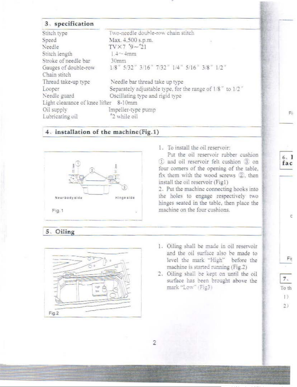
I.
To install the oil reservoir:
the oil reservoir rubber cushion
Put
C"G
and oi I
four comers
rix them
install the oil
2.
Put the machine connecting hooks into
the holes to engage
hinges seated in the table. then place the
machine
re~ervoi
of
"ilh
reservoir (Fig
on
the four cushions.
the
the
r
opening
wood
felt cushion ~
of
the table.
screws %. then
I)
respecti
\ely
t\\
on
o
c
5.
O
ilino
- ---
I.
Oiling shall
and the oil surface also be made to
le'
el
the mark
machine is mr:ec ru;ming (Fig.2)
1.
Oiling
surface h3S
mark
··~
be
mad.: in oil res.:n·oir
"H
igh
..
sha
ll oe kept
on
bee:1 hought abovf! the
(\\\
· -·
...
·
2
before the
until the oil
~
To th
I J
Page 8
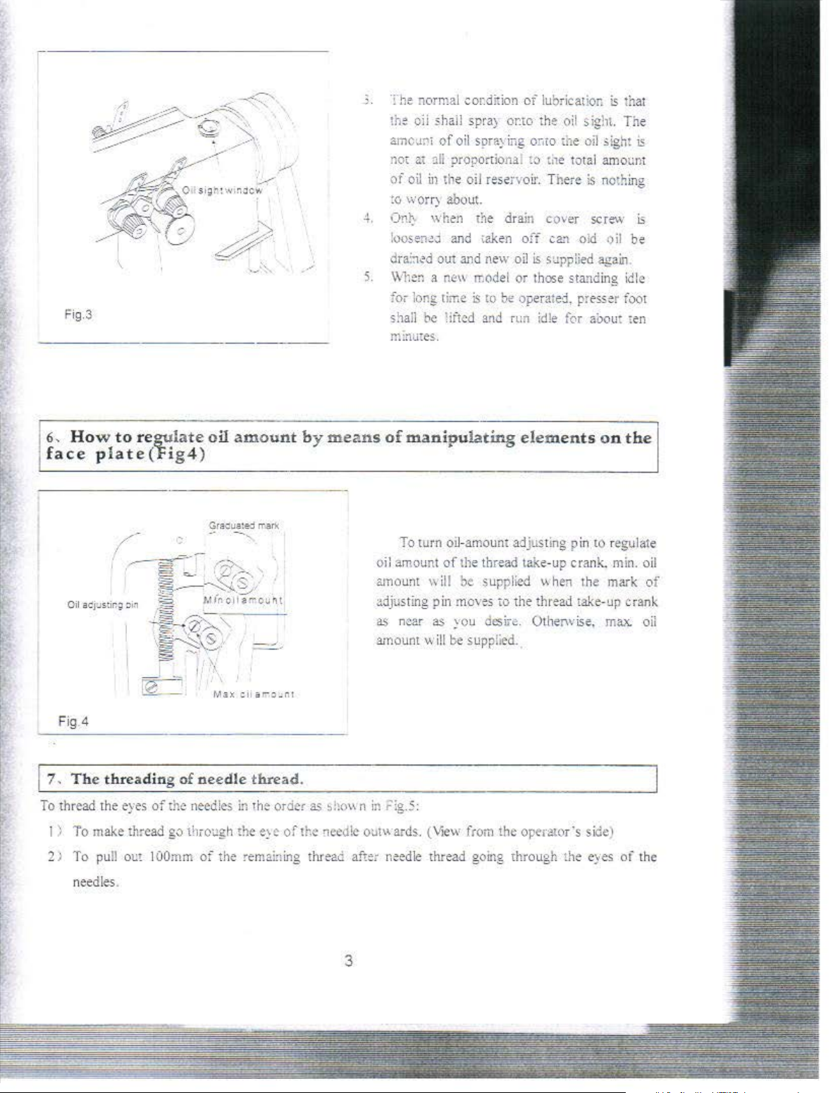
Fig.3
.>
. The normal
the oil shall spra) or.to
amcur'i
not
at :tlf propordon1l
oi
oil in the oil rese;·vo
:o
worr) about.
4.
Ont.. when
loos
e~~"
dra::,~d
S.
\V11
en a
for long
shall
m:nmes
be
of
oil spra;
and
out
and
n~"
rime
:ifted
.
cor.d!tion
is
1he
drain
taken
new
model
co
be
and run
of
lubricati
the
oil sight. The
ing
omo the
~o
ti
1e
total amot:nt
ir.
There
cover
off
ca~
old
oil
i;
supplied
or
those standing idle
operat
ed,
presser
idle
for
on
is
th
uiJ
~ight
is
nothing
scre\v
•>il
again
foor
ai>out ten
at
is
is
be
.
6,
How to regulate
f
ace
plate(Fi
(
' I ,
,.--
Oil
ac
'j:Jstir.~
;,i~
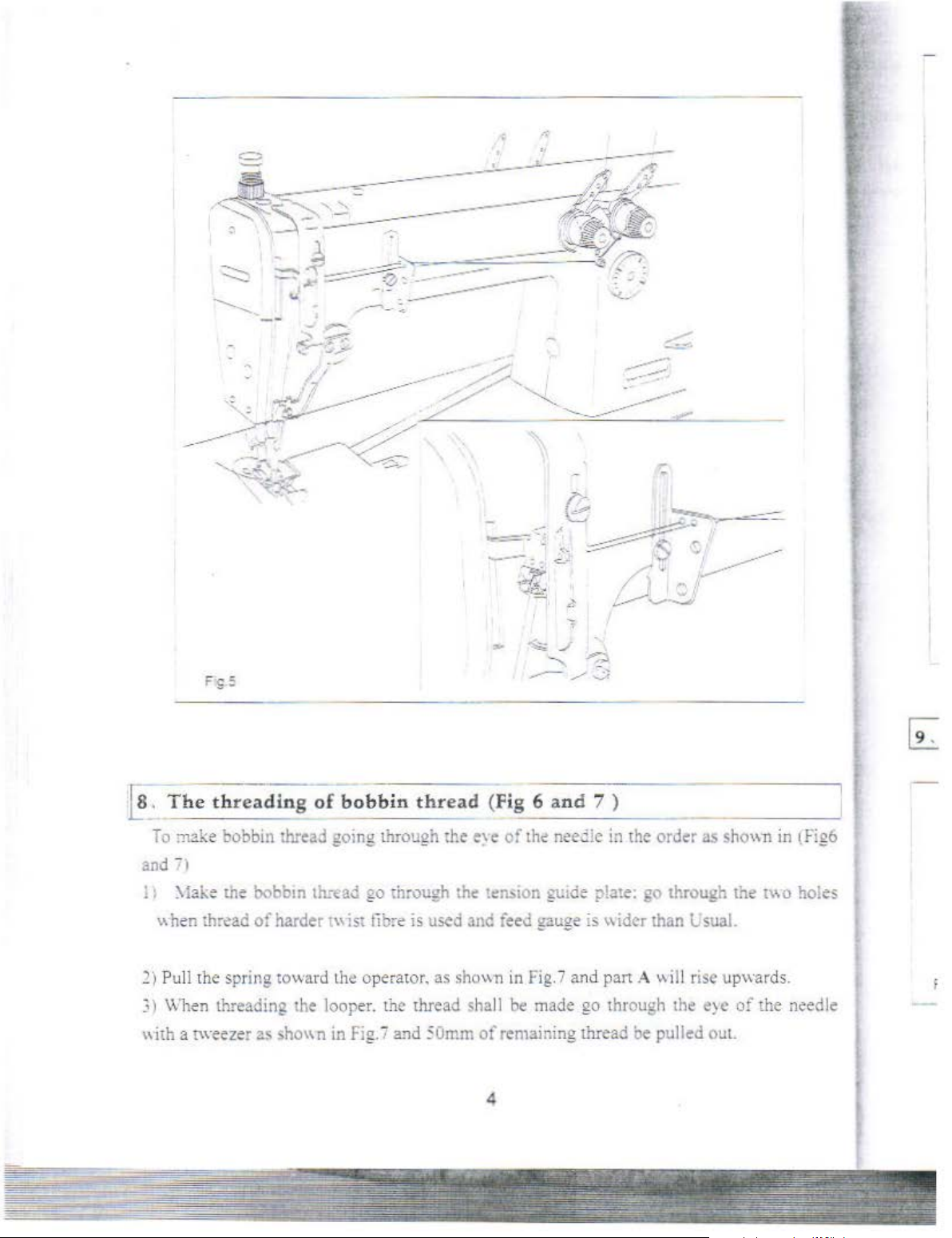
Fig.4
7, The
To
thread
threading of
the
eyes
~
of
g4)
. • I
·
(he
needles
oil
need
amoun
le
thread.
in
the order as
t
by
means
oil amount
~hO\\
n
in Flg.5
of
manip
To
amoum
adjusting pin moves
as
n~ar
amount
turn
\\ill
w i!l
ulatir..g
oil-
of
as
~ou
be
amoum
the
thread take-up crank. min. oil
be
supplied
desir~. Othef\vi.se~
supplied.
:
elem
ents
adjusting pin
"hen
to
the
thread take-up crank
the
on
tO
regulate
mark
max.
the
of
oil
~
~~.:::=-~---
·
I )
To
2 I
make thread
To pull
needles
out lOOmm
.
go
through the e:c
of
the
of
the oeed!c
remabing thread after
0\lt\\ards
. (\.1ew from
n~edle
thread going
the
through
3
oper&or's side1
L~
e
eyes
of
the
Page 9
. ,
~,
The
threa
~
To
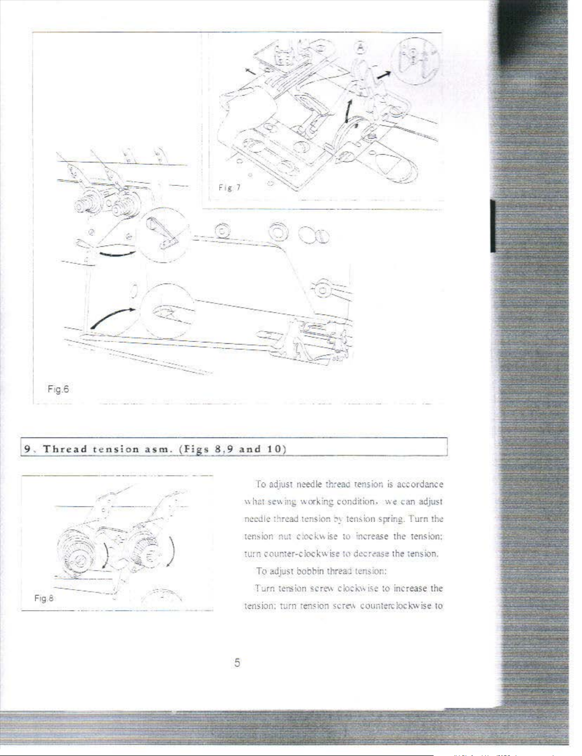
:nake bobbin thread going through the e\'e
and
71
11
:\lake the bobbm th:tad
thr~ad
when
2)
Pull the spri
))
\\ 11en threading the looper. the thread sha
"ith
a tweezer as
of
ng
of
bobbin
go
through the
harder t\\ist tibre is used and ieed gaugers \\idcr than UsuaL
toward the operator, as shown in F
.ho"n
in Fig.7 and
thread
~
Omm
.,.,
...
.,/
.......
~
---/.:;;
(Fig 6
ten~ion
ll
of
remaining thread be pulled out.
4
and
7 )
of
the nee .:lc
gt:id:
ig.
7 and
be
made go through the
in
;>!ate:
pan A "ill
the
ord~r
go through the tv.o holes
as
•ho"n
rise upwards.
e)e
in l
of
the needle
F!g6
Page 10
--------··
Ftg.6
_
--
~--·
-.......
r;::-
---·~-
-
~
~
___
__
:._:,__
,;~;-..,
~.::.-:::
~ ~
·-......,.
J'
\.
,-
...__;.:':._
..
9 . T
F•g.a
----~
hre
-----
ad
-----
t e
·-
nsi
..
·~
o n
asm.
-
--
(Fi
gs
8 ,9
and
10
)
ro adjust
\\
he1
necJic
ten~
ion
n~edle ~h~eao
se\
•.
m~
v.:ork:ng
\hread
l~nSiOn
:H.:t
c
:oc k '"
wrn coun;er-ciockwise
To
adjust bobbin
Turn t
e-ns
km
sc rt\' clot
tension:
rurn
renskm
tension
condition.
:"1~
tension spring. f
ise-
to
~ncreas
hJ
dec:rC"ase
thr~ao
ton;klr::
f..:\\
ise
screv.
counterdock."Wise
is
accordance
-..ve
can
e
the
the
H:msion.
to
incr
:.Jm
tens
eas
adjust
th~
ion:
e t
he
to
5
Page 11
.--
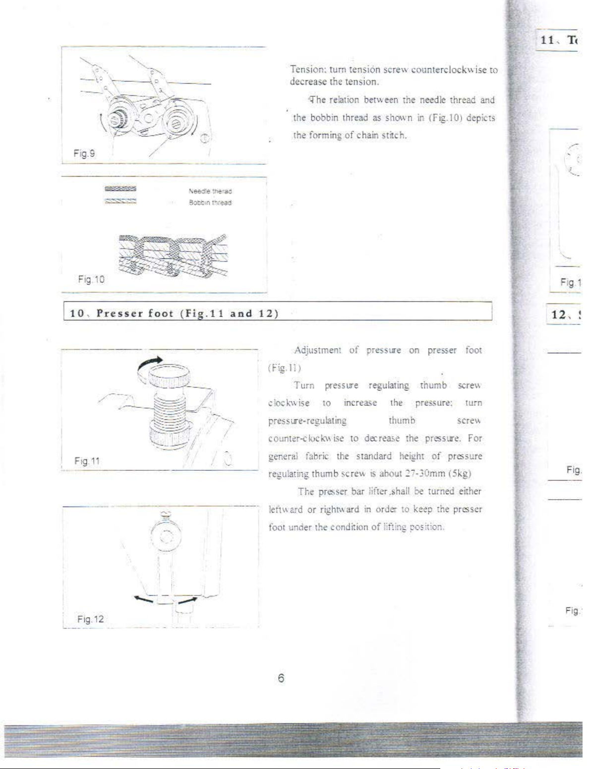
Fig
-----
10
--
\ee<l'!e
E!o:t
1n
tMr
l"'te3j
ac
Tensi
on~
decrease
-Q'he
the
bobbin
the
forming
turn tension
the
tension.
relation
thread as shown in (Fig.IO) depicts
of
::;crew
between
chain stitch.
counterclockwise
<he
needle thre
ad
ro
and
10, Presser
flg.11
foo
t {f ig.ll
'
and
1 2 )
Ad
jusilnem of pressure on presser foot
(Fig. ll
dock."\\·ise
J
T u
rn
p.
·essure regulati
i.O
pressure
counter-cloch.'\\
general i
regul
left"
foot under the condition
..
regulating thumb
Lie
abric
the
ati
ng thu
mb
sere"
TJ·.e
pre.ser bar l
ard
or
right\\ ard in or de. to
increa~e
to
standard height
the
decrea~e
1S
ahout
ifte
r
.shall
of iif!ing
ng
thumb sere\\
pres..~ur~:
sere''
the presstl'e.
of
pressu
2i-3
0mm (5kg)
be tumed e
keep
the presser
pos
it:o
n.
turn
For
ithe
re
Fig
.
r
F1g.12
6
Fig ·
Page 12
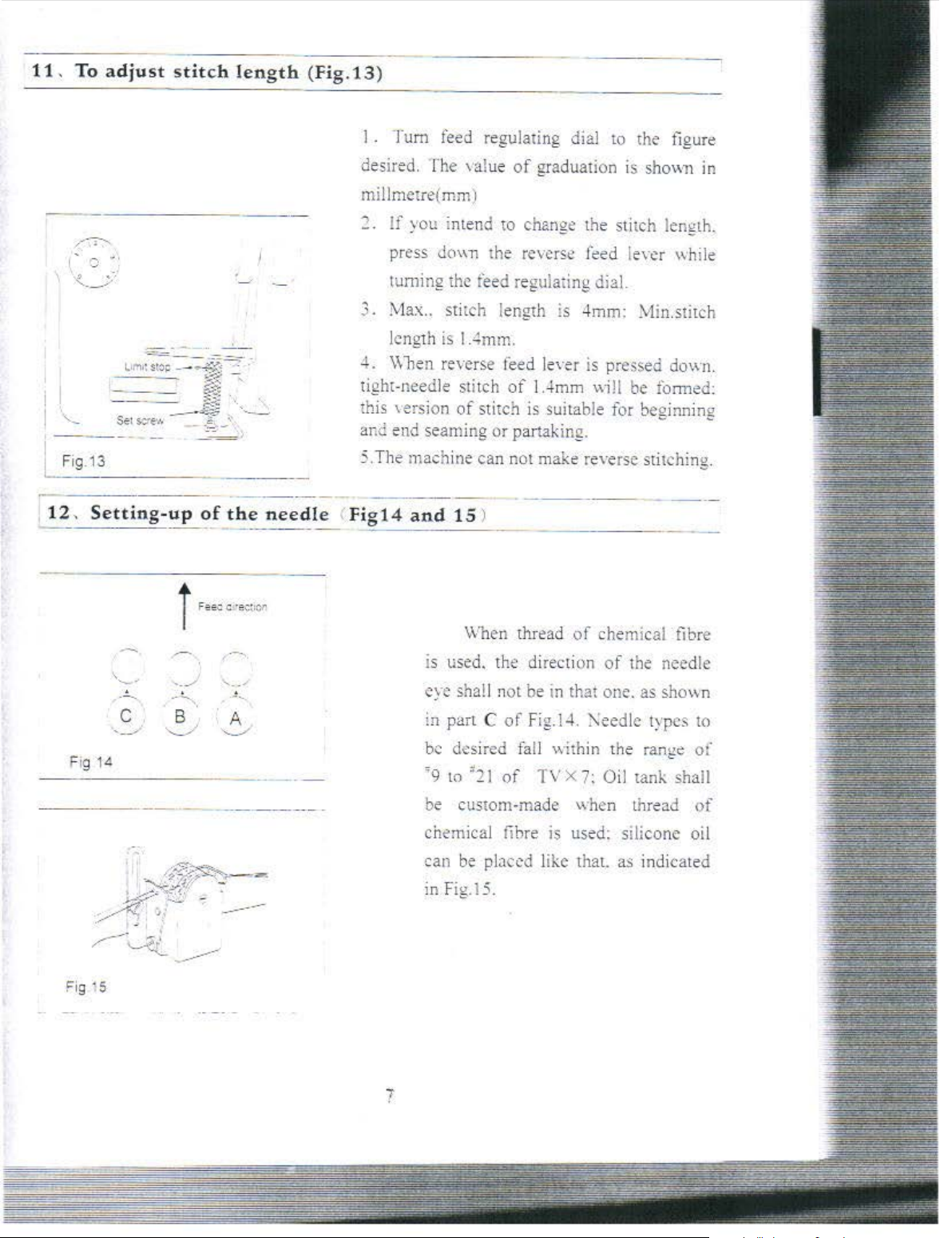
1 L To
adjust stitch
length (Fig.13
)
/-~
I
..
.)
'Z._Y
Fig.13
12
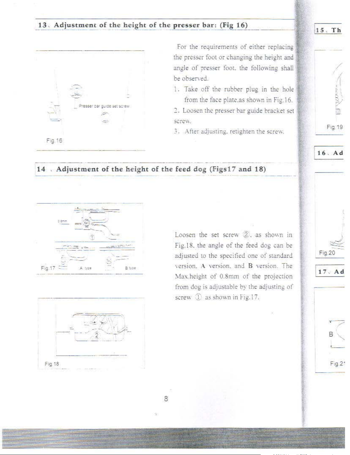
,
Setting-up
..
..
I . Tum
desired. The ,·aJue
feed
regulating dial
of
graduation
to
the figure
is
sh0\\1
1 in
millmetre(mm)
..,
If you intend to change the stitch length .
press
'
do"n
tuming
3. Max.. stitch length is
length
-+.
\\
l1en re,·erse
tight-needle stitch
this
'ersion
ana
e
nd
seaming or partaking.
of
the
needle <Fig14
5.The
machine can not
and
the reverse
the feed regu
is
1.4mm.
fe
ed
of
of
stitch
15
)
f~ed
le,·cr while
lating dial.
-+
mm:
.:vl
in.stitch
Je,·er
is
pre
ssed
1.4
mm
"ill
be formed:
is
suitable for beginning
make
re,·ersc stitching.
down.
Fig
1<~
Fig ·s
c
> •
_
......,_
B
-..._/
\Vhen
IS used. the direction
../
.....
.. /
, _
A
'-._/.
eye
sha!l
in part
be
desired fall within the range of
'9
1o
'21
be
cus10m-made when thread
chemical fibre
can
be
ig.
in F
thread
of
chemical
of
not be in that one. as
C
of
Fig.!
-1
. ?\eedle tvpes
of
TV X
7:
Oil tank shall
is
used: s
placed like that.
l5.
t
he
ili
cone oil
as
indicated
fib
need
sho"
re
le
n
to
of
7
Page 13
-
_
-13
-
,
_
A
_
d_
j
_
-u-
s
-
~_r_n
-
e
_
n
_
t
_
o
_
f
__
t
_
ll
_
e_h
-
~-~
g
-h
_
t
_
'!_!._t
_
h
__ e ___ p_r
_e_s_s_e_r_b_a
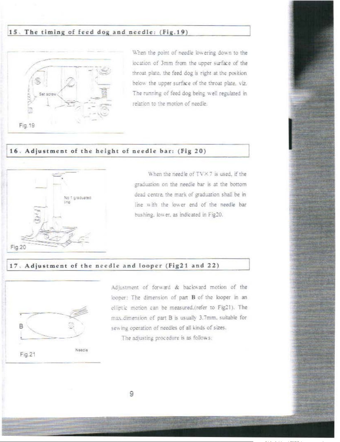
F
or
the requirements
__
r-:-(F-~
-
g
-
1
_
6
_
)
-
-
.==1
of
either replaci ng
•15.
Th
Fg
16
-
--
---
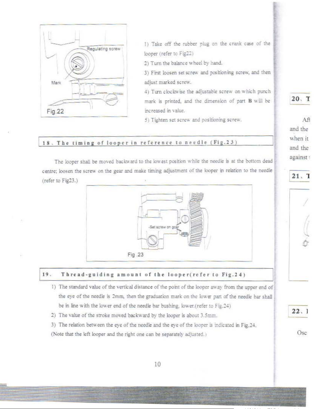
14 . Adjustment
_
::.""~
---
-
----
-~--=~;,·
=-:~-~
-
---
.:
.,__
--
I
-
of
==
-
~
~
the
-'
• .
, __
~'
~.
- -
-- -
height
,..
_ --.
the presser
angle
be
obs
1 . Take off the rubber piug in the hole
from
~.
Loosen the presser bar guide bracket set
SCTC\\,
3. After adjusting. retighten the sere\\.
----
..
of
-
----
the
feed
Loosen
Fig.
adju
'e
:vtax.hc ight
I
sted
rsion. A version.
fo01
or
changing the height and
of
presser
erwd.
t
he
-------
dog
the
8.
the angle
to the speci lied one
fooL
face plate.as shown
--
(Figs17
set
screw
of
of 0.8mm
the
fo
llov.ing shall
----
and
18)
:.?.:.
as
the f
eed
and B ve
of
the projection
in
Fi
g.16.
-
sh0\\11
dog can be
of
standard
rsion. The
in
Fig 19
lt6.
Fig.20
1
17
,
/
Ad
Ad
from
dog is adjusta ble
scr
ew
J• as shov. n
r-==r=;='F'
-:.!...
~
,\1
"-
·- - - _.-2 ·--""':' -
-= -:
'I
~
- -
- - - - - - -
Fig.18
----
8
by
the adjusting
in
Fig. t 7.
of
8
·-
"--
-
Page 14
15
. T
he
timing
of
feed
dog
and
needle
'.\:-.en
: (
Fig.19
the point
)
of
n~dlc
~\\
ering
do\'
n to the
16. Adjustment
--
--
i\:;
1·-e
of
•
. -
the
;~:va•ec
-
-
--
\.....:...-
height
-.
location
throat
~eio"
lJ;e
r"!:~~:v-
of
needle
.gra~w::ion
Jead
line
bushing.
of
plat~.
the
upper surface of the
ruor.ing
iO
·~e
~entre.
"ith
lo"er.
3mm from
the feed
oi
feed dog beinf " e
r:'IOliO!'l
bar:
o~
tne
the rrark
the
lo"
th~
dog
o·-
(
Fig 20)
needk
of
cr
end
as indicated
upper ;urfoce
is
right at the
L'troat
!:
needle.
bar
is
at the bottom
grad~ation
oi
the needle bar
in
Fig20.
of
the
po>it
ion
plate. ':Z.
regulated in
shal: be
in
111.
Adjustment
8
-·
-
--
F1g
21
~--
of the n e
__
__..
Neece
edle and
.~diu•tment
'oon
.or:
d!
~::C
tl:-\.
. .:irre"sicln
sew'"!; "i)Cration
The a.:l.'usting procedure
loop
oi
:orward &
The dimension
mo:i<m
'""
ci
9
er (Fig21
bac~"'ard
of
paJt B
be measured.< refer
part B
of
ne,'\fles
is
u~ual~
of
~II
i<
as fol!m• s.
and
of
3.-mm.
kinds
22)
motion
the
looper in an
to
Fig:
<unable for
of
;,,zes.
of
I).
the
The
Page 15
~C./
Fig.22
18
,
Tbe
I
~---.---..---=~~
.,-
-----------
tim log
of
~
looper
1)
Take
off the rubber "lug
loo
per lrefer
1)
Turn
the
3)
First
loos
adjust marked screw.
4)
Turn clod:wi:;e
mark
is
printed.
i:lcreased
5) Tighten set screw and
in
refe
in
renee
to
F1g:
2 1
balan
ce wheel
en
set sere-' and
the
and
valu:.
to
needle
o~
the
cra.~k
by nand
aJ;ustab~
the
dimension
po
?O>il
ioning
ser
siti
oning scre
(Ftg.
.
e"
of
2 3 )
case
screw,
on
which
pan
w.
of the
and then
punch
B will
be
20
, T
Ail
and
the
when
it
and the
The
centre;
(refer
19 .
loosen
to
l'ig23.)
Tbrcad-guidlng
I) The standard
the
be
2) The
looper
the
eye
in
line
value
shall be mo'
scr
ev.
1ln
,·aJue
of
the
needle
"ith
the lov.er
of
the stroke
ed
backward to the lowest
the
gear and make
Fig
amount
<lf
the
vertical distance
is :!mrn.
end
of
moved
then
the
backward
timing
adjustment ot
,-
---
I
·
5&·
~
-.,S.-J
-
~__j
.23
o f
the
of
the
the
graduation
needle
bar busning,lower.(reier
b~
the
position
while the
--<a
loo
per(tcfcr
point of
mark
looper
the looper
on the lower
is
abo
ut 3.5mm.
the
needle
looper
to
awa}
part
to
is
at the bonom de
111
relat
ion
Fig.24)
from the upper
of
the
fi~.:~)
to
needle
the
n.:edl
e~d
bar shall
ad
e
of
agains
21,
'-
- -
22
t ·
1
I
I
. I
3)
The
relation
(Note that
the
bem
left
een the
looper
eye
and the
of
right
the
needle and
one
the eye
can be separate
of
the
ly
adjusted. '
10
Ioeper 6 :-.cica:ed
in
Fig.2-1.
Osc
Page 16
Flg.
24
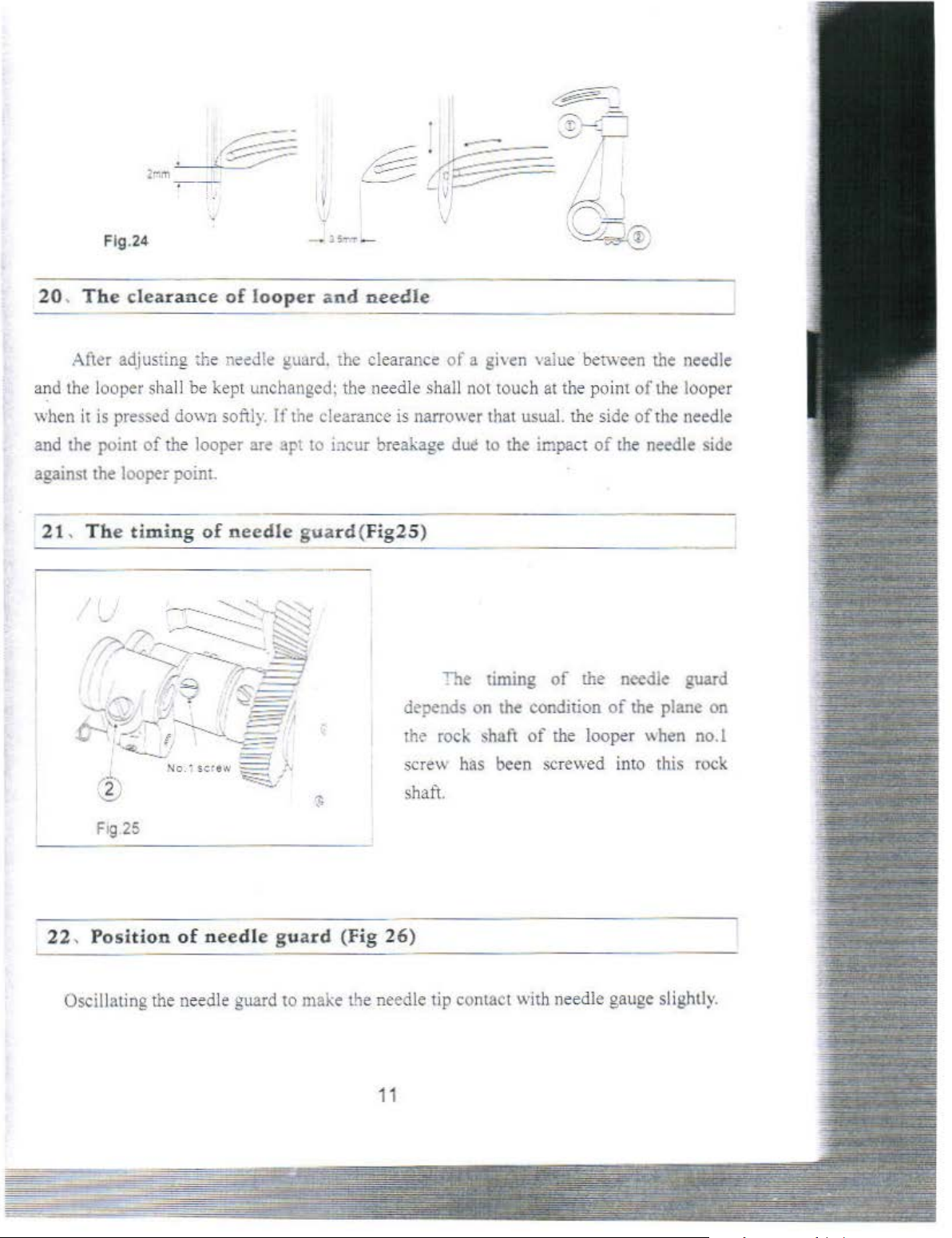
20, The
After adjusting the
and the looper sha
when
and the point
against
21, The
clearance
it
is pressed dov.n softly. If the clearance is narrower that usua
of the looper are
the looper point.
timing
of
looper and
needle
--------------------------
n~ed!e
ll
be kept unchanged: the needle shall not touch
of
needle
guard. the clearance
apt
to
bcur
breakage due to the impact
guard(F
ig25)
dl?pends
the rock shaft
of
a given
"':le timing
on the condition
\alue
at
t
he
l.
the side
of
of
the loope r
--
between the needle
point
of
the looper
of
the needle
of
the needle side
the needle guard
of
the plane on
\\hen
no. I
22, Position
Oscillating t
he
of
need
le
needle guard
sere\\ has been screwed into this rock
shaft.
guard
to
(Fig 26)
--
--------------
make the needle tip contact with needle gauge slightly.
11
--
Page 17

lt is re
commended
that
the
height
23
,
Looper
,·--
-
thread t
ake-up c
adj"Jstment shall not fall within
the left countGr needle guard. The
adjustment
ser
e"
left
needle guard is
the
clearance
the
range
needle shall
machine
am(Fig27)
can
be made
(!~and
count
;-Jote tl':at the forced
X. The
er needle guard
as
represenied in Fig
rrom
the needle falls within
of
0.1
ro
0.2 mm.
b.:-
prohibited
is
in
n1otlon
.
- - - - ·· -
the
b
~
relation
and
the
clamp
--
area
or
loosening
between
counter
26;
of
the
"hen
the
---
Fig.28
25,
Fr.
The
skipping
The
Conon
th
Fig.27
~--
-
24, The
position
of
--
the
thread-amo
Its position
fig.27
when
dead centre.
the steel
projec
ting
rise
at the
first loosen screw
adjustment. linall;- tighten
firmly. P
can
be se
en
the
needle bar is at the
the
planes
wir
e are in parallelism: the
part
of
angle
a'
close attention
of
the
cam can slightly
ot'
18
10
B.
and
rollowing: the needle tip
come
wh
into
the
rhread
en the
the projecting pan
bobbin
loop
thread rejecting from
of
the
cam.
as
shown
the
cam
::!0
degre
then
the
sha
ll entire!)
or
the looper
mak
sere\\
to
in
top
and
es.
the
Conan
Thread o
Thr
e
ead
th
o
26, RE
-
unt
adjusti
ng
plate of t
he
thre
ad
take-up
lever:
(Fig 28)
12
Page 18

Th
e thread-amount adjusiing plate will
retain the bobbin at thread when the needle bar
is
the bottom dead centre:
of
the needle thread is to become bigger when
the
n
e~dle
thread is hooked.
in
such a way the loop
In
addition to the
Flg.28
25
, F
rame thread
The improper-posit ioning
skipping stitch.
following location> are ge:J<'raliy
The
Cotton thread
Cotton thread
Thread
Thread
'80-'50
'80-'5
of
chemic
of
chemical fibre
a!
foregoing there is a function
of
eyele~:
(Fig,
-'2::.:
9'-')'-------
of tile
frame thread eyelet rna)
Graduation marked on the frame thread eyelet 2-3
the needle thread loop.
adjusting plate usually reduces
point when a thread liner than nonnal
"'ote
that take- up thread tension le,·
another name for thread-amoum adjusting plate.
-----
be
r~garded
as criteria (refer to Fig29)
The
the cause
0 Gradumion marked on the frame thread e
:i!:>rc '80
'8
-=s
o Graduation marked on the frame thread eyelet 1-2
0 -
-'50
Graduation marked on the frame thread e}elet 2-J
of
the light pulling
thread-amount
to
the
is
used.
-
--
of
occurrence
yelet3
--
]o,~est
er
IS
of
-4
/ -
·"(
,._
---::.
.
26, Replac
ement
of
throat
plate:
(Fig
.30
)
13
"
--==
--=-----:__--=----------
----~-
----=------
~--
-
Page 19

Fig
30
The
standard size
book. which
I
.; .equi,·alent to 6Amm.(Fig.30l
The
is
usuall)
gauge
of
ts stipulated
replacement
needed
double-row thread stitch.
1.:\eedle
3.
Throat plate
needle
the si
of
the width
guard
The
left
and
zes
of
I 8 "
In
addition
slide plate and
of
thread plate is on the increase.
of
the throat plate
by
the oanufactory. is
of
the
following components
at
the
time
when
clamp "
~.Feed
6.Curle~
right
to
to
the aforesaid.
cam
dog 5.Rear mo,ing
loop
ers \\ithin the
I '2 " are interchangeable.
cov
er shall be
changing
Hinged
the
replacement
made
in
pans
range
when
the
foot
of
:!8
~
i'
I
''
I
I
I
~
, o
mm
o
Brea.~down
Thread
brea~age
-
---
27, Maintenance
The
(I
I .
II
. Repairman shall
---
----
of the mac
follow~ng
)
Daily
The
oil shall spray onto the oil sight when the machine
shall
be
checking
be
machine.
(2)
I .
wi
th
I!
.To
the oil reservoir
Locations
To
take off throat plate. slide
to
be
a brush.
turn o\·er the
head
of
oil stain and dust.
In Loosen drain hole sere"
reoil
it.
1\
.Oil Je,.
V .The
eJ must
black
be
abo'e
powder. adhering
sponge cloth.
---
-
----
hine
adhered
sent
checked once a wee
to
in
order
to
keep
for
when abnormal sound
k:
pla
te. and cam co\ er;
rid both the oil filter screen
and
take it off; drain all
th~
lowest oil-level-indicating line marked
to
the
magn~t
-----
the
machine in
to
the
in
the
-
-----
good working
is
running.
is
heard during the operation
clean
dust of
on
the
oil
dtn~
oil
oil resen,oir shall
the slotted
pump
from
and
the interior
the oil resen oir and
..
Low
..
be
conditi
feed
wiped
on.
of
with
~
the
dog
of
~~
i•
I '.
-
I
1:
I
1:·
1:
Skipping
stitch
14
li
1·
:
Page 20

li
1
~
[2 8 , o m m o n
breakdowns
and
measures
of
trouble
shoo
ring.
I
'
:
~o.
I
::
,'
~
I
'
2
Breakdown
Thread
breakage
Skipping
stitch
Cause
I Poor thread quality
2
T~.read
3 Fusing thread due to h
temperature
caused
operation at
4 Tension
Breakage of
5
lo
oper. :hroat
needle guard
of
thread guide
6 Failure to adjust thread
amount
!.Skipping stitch
thread
due to
hook the needle thread)
being t
oo
thick
igh
of
needle
by
J:llt::hine
high
speed
being too higher
needle,
plaie.
at
the
of
(leaking of two stitches
the loopers failure to
and
location
needle
Measures
I.
Qu
ality
thread to
2. Replacement to
s
3.
Silicone
4. The tension nut to
5.
First grinding with oil stone
6.
Adjusting the thread
1,
2, Adjusting clearance between looper and needle.
3
...
4, Adjusting the thread-amount adjusting plate on
5,
6
'
7,
8,
oil
Adjusting thread-hooking amount
The
riming
arnoum changing conditions.
thread
Adjusting the
Checking
needle
is
To see
appropriate
regulated
To
see if the
way.
be
be
to
be
used
of need
frame
wh~ther
proper or not .
if
the location
way
in
relation
needle
ro
be
taken
used.
made
by
an
appropriate thread
anc!
speed to
be
loosened
and
an10unt adjusting
le
in
referenc
thread
the mounting position
of
and tbe t
to another.
thread threading
then
e to
eyelet.
need
iming
be
of
le guard
reduced
polishing
plate
looper .
looper.
of
it
is
in
of
the
is
in
an
is
weD
a proper
I)
2.skipping stitch
thread (leaking
needle
looper
J.Skippin¥ stitch when thread
of
failure
eyelet)
chemical frib
of
of
one stitch.
to
enter the
re being
bobbin
ht
use
Reference to
of the
stitch
To
sec
2)
we
t!
regulated.
3) Increasing tension
4)
To
see
correct
I) lising sillicone
2) Reducing
3) UsiM
need
the
above cases I
needle
of the
if
the
timing
of
if
the threadine of bobbin thread is in a
wav.
oil
spee<i
!e
for
threw of chemical
15
and
2.
as
needle
thread.
of
bobbin thread cam has
bobbin thread a bit
fibre.
to skipping
been
higher.
Page 21

3
s
Tv.
is
ted
sthches
Breakage
needle
Puekeril:g
.!,Sk.~pi:lg
of
po~ester
1.
~eedle
too
low.
stitch
"'cen
libre ;eing
thread
tensio~
2. Bobbin thread tension being
1
100
low
3. Sewing thread
thick
.J. Improper
f:-am~
5.
l:nproper postior.
:a{e-up
6. Throa1 olate
1) '\eedle
:!
) The openuion oi
thread
tension
being
poeiltion
C:)'eltt.
plate
bent.
beil:g not "eO regula:ed
refe
rence
to
the
needle.
3) Sening-up
of
4}
The problem
of
f()Ot
n<cdle
of
the presser
of
guard remain
unsolved
S)
l\ed[e
[00
6l
:-;eeele bein£ roo thick. 1
1
3
thread
tensi~n
bigh.
Ttr
ead tension
~ig;:.
Tne problem
of
the bobbin thread
~or
!0
t.'lread
be
guiding iaihng
solved.
The problem
fmish
arising
th
read
going 1 hrough the
par
ts on the thread
T
he
force on the
foo:
bem<:
too area!,
of
oi
from bobbin
're•j
~,
..,~
b~mg
being
tOO
of
the S, Readjusting
of
:hread
feed
dog
r.1otion
the
timing
being
bei:1g
too
the timing
cam
sunac<
guide.
pres.>cr
Re~::ci:15
Silicor:.:-
I,
Tightening
:!
. Tightening tension nut
3,
l\eedle
4,
Readjusting it to a proper posit
6.
The eye!e;
than
normal on
11
in
of
bg
'-:eedle to be :eplaced
~
l
Readjusting the timing to feed dog
n~cdle.
3)
To
ma.'<e
foot
and the
4)
The positioning
be
taken
5)
Relaxing
6)
Appropr'ate
I.
Decreas=:g
thread.
2.
Readjust'ng
proble~
3.
Surface
4.
Turning counter-clockwise
screw.
.;peed
o:J
!O
;e
-.)~..!
tension nut
of
large
size to
its
;lOS
of
throat
e.
both the centre
centre
of
8:
the tuning
into
account.
need!~
thread
needle
to
th."ead
of
the
'<f)
.
fmishing
all
of
needle
thread.
of
bobbin thrcdd.
be
u;cd.
ion.
ition
in
an
appropriate way .
plate
to
be
used
being
bigg
by
another
the
be
used.
t<nsion,
cam
of
the
eyelet
of
esp.
said
oi
proper size.
in
respect
hole
of the pres
of
the throat.
the
needle
t:nsion
to solve the
guard 1
oi
bobi>;
tim
tot
the parts on the thread guide.
the
pressure-regula
tin
I
I
$
in,
~
,,
),
~
6,
-1
7,
t
8,
~1
9,
11
10,
lL
12,
1
13,
14,
lii
Page 22

Contents
P
arts
l,
2,
3,
4,
5,
6,
7,
Book
Ann
Bed
Components · · · · · · · · · · · · · · · · · · · · · · · · · · · · · · · · · · · · · · · · · · · · · · · · · · · · · · · · · 1
Main Shaft & Thread
Presser Bar Components ·· · · · · · · · · · · · · · · · · · · · · · · ·· · · · · · · · ·· · ·· · · · · · · · · · · · · · 5
Feed Mechanism Components ·· · ·· · ··· · · · ··· ··· ·· · ·· · ··· ·· · · ·· · · · ·· ·
Feed Re<>ulatina Components · · · · · · · · ·
Looper Thread Retainer Complete · · · · · · · · · · · · · · · · · · · · · · · · · · · · · · · · · · · · · · · 11
Thread Take-up, Tension, And Tension Releasing Assembly
,
"'
Bar
Components ·· · ··· ·· ·
···
· · · · · ·
··· ··· ·
···
··
··· ·· · · ·· ··· ·· · ···3
· · · ·· · · · · ·· · · ·· · · · · · · · · · 9
···
·· · 7
complete
8, Lubrication Components · · · ·· · · · · · · · · · · · · · · · · · · · · · · · ·· · · · · · · · · ·
9,
Oil Reservoir & Knee Lifter Components · · · · · · · · · · · · · · · · · · · · · · · · · · · · · · · · ·20
10,
Machine Head Accessories · .. .. · .. · ·
11,
Quadruple-thread Spool
12,
Machine Stand, Table, & Electric Appliance Components ·· · ·· · · · · ·· · 26
13, Model
14, ZJ3800N, ZJ3820N
One
-needle High Speed Chainstitcher · · · · · · · · · · · · · · · · · · · · · · · · · 28
· · · · · · · · · · · · ·· · · · · · · · · · · · · · · · · · · · ·· · ·· · · · · ·· · ·· · · · · ·· · ·· ·
..
. · · · · · · · · ·
....
Stand
List
.... · ....
Asm. · · · · · · · · · · · · · · · · · · · · · · · · · · · · · · · · · · · · 24
Throat
of
& Its Accessmies
· · ......
· · .. · .. ·
........
..
· ·· · 14
.. "31
18
· 22
Page 23

Arm bed components
L
Re
f. No.
I
2
3
4
5
6
7
8
9
10
I I
12
13
14
15
16
17
18
19
20
21
22
23
24
25
26
27
28
29
30
31
32
33
34
35
36
37
38
39
40
41
42
43
44
45
46
47
48
Part -:o
GQ202fl3
GS01Z7
GR\823
GKI86
GR1812
GS
IOO
GR 1757/2
GR1758
GS!OO
GR1458
GR!813
GW287
GRI814
GS069
GM241 /\Ltachmenr
GW288
GSOi28
GS012
G\-!242/9
GM243
GW289
GW29
GS045
GR 1815
GS0129
GM244
GM245
GW291
GS045
GR1816
GS0
GW292
GS010
GR18
GS44
GRI8
GSOIO
GSO!O
GR146i
0
/6
!29
l7
1R
GRJ8!9
GR1462
GR
1~63
GR l
"o'"
GR1465
GR!466
GR19
!6/5
GRI923
GS0
!48
Description
Arm
bed
Bed sc
Bee s
Side p l
Gasket
Side
Face
F
Sc:evv
Rubber
Can
Spring
Spring
ace
rew
upport
ate
plate
;:>late as
plate
--
plug
cover
suspension
Scre'v
Spring
Screw
Screw
Cam
Cam
Cam
Sp:ing
Screw
Sc
cover
cover
cover
Cam cover
rew
slide
Bed
Bed
slide
Spring
Screw
Bed
siide
Scre\v
Bed
slide
Screw
La;:ch
Screw
Bed
oil
shie
Screcw
Bed
oil
shie
Scn
:w
Rubber
Rubber pl·
Rubber
Rubber plu
Rubber
Rubber
Folder
Gaske
Screw
t
cornpiete
stud
screw
m.
gasket
late~
installing
asm
guide
asm.
guid
e
lock
spri
ld
ld
plug
ug
~lug
g
plug
plug
ng
plate
Ann.
Req.
I
2
1
I
I
8
I
l
3
2
I
I
1
1
I
I
2
I
(!)
1
l
I
..
I
I
(1)
I
l
2
I
1
1
2
I
I
J
2
1
2
~
2
2
tK
;to-
42
~
32
~~
33
34
v r
35
~-:
1
l
Page 24

Page 25

2..
lVIain
shaft & needle bar co
Ref.No. Part No
l
2
3
4
5 GZ303
6
i
8
9
10
1 l
12
13
14
15
i6
17
!8
!9
20
21
22
23
24
25
26
_,
T
28
29
30
'.
.:'l
32
33
34
35
36 GSOl30
37
GS02
GPi 32
GS03
GRI-!68i2
G0262!2
GRI824
GS33
00265
GS05
G0303i2
GS04
GR1470
GX33-!
00269
GR147l
GH378
GS06
GRt472
GS07
GH379
GS48
G$
GH33.:i
G02i0
GS09
00271
GS012
GRi-!79
G0~88
GRi47~
GSO
GL168
GZ304
GR l
G
Vi8
041
826
l i
mp
onents
A
Description
End screw
-.vhee
Hand
Screw
Oii seal
Main
:Viain sna
:V1a:n
Screw
\fain
Screw
Main
Screw
ol
ler felr
R
Crznk oil adjus,ing pin
Rubber bushing
0-Ruboer
Counterweight asm.
Screw
0-Rubber
Screw
=-'eed
Screw
Scr.!w
~eed1e b~r
Needle roiier bearing
Left twist screw I
.Kcedle
Screw
Rub0er plug
:\ceoie
·'\eeri!e
Scn:w 1
Crank slide block
).leedle bar
:--ieed!~
Screw
!'\eedle
l
shaft
f<
bushing. rear
shaft
thru;t
shaft bushing intermediate
shaft
bushing. front
rir.~
ring
le crank
bar
bar
bi:ir
clamp(l/4"
colla
:
crank rod
bushing upper I
bushing. lower
~on~ection
asm.
)
rm.R
I
2
l
2
-!
I
2
1
l
l
I
I
l
I
I
I
1
I
1
I
' 1
2
2
eq.
15
1s 1 .
14
\ I
"-~6'
~
I
,.,--c::r-1
-~~:<'
~
12
~
~
L-
26
\
~-
3
Page 26

12 11
I
:~
1
30
____ I
----
<;:;'
34----
_j
~
"'
"
'
0
3
"'
Page 27

Presser bar components
3,
Ref.No.
1
2
3
4
5
6
7
g
9
10
il
12
i3
14
15
16
17
18
19
20
21
22 GR I 5
23
24
r
26
27
28
29
30
31
32
33
34
35
Pan
No.
GS018
GL18
GRI494
GW253
GZ305
GR
I82
7
GS0!9
G0273
GR1525
GM246
GS020
GR
1832
GR1833
GS0129
GR1499
GS021
GRISOO
GRI50l/2
GRI503
GRt504
GS022
05
GS023
GS024
GR
1506
GRI508
GRI507
GRJ834
GS025
GRI510
GRI835
GS0131
GR
183 6
GX378
GLl9
/5
Description
Presser spring r
Nut
Pr
esser bar
Pre
sser
Presser
Presser
sc~ew
Press
er
Oil
wick
Presser
Sc
rew
Thread
Thread
Screw
Hand
Screw
Washer
Hand iifter
Rubber ring
Lifting
Hinge
Lifting
Hinge
Hinge
Lifting lever
S
:1ap
Snap
Lifting lever
Screw
Snap
Lifting lever link
Hinge
Swivel
Lifting
:>Jut
spring
bar
bar
bar
foot
knife
knife
lifter
lever
screv..-
link
screw
pin
ring
ring
ring
screw
lever
guide
guide
bush
asm.
guide
cam
for
gasket
connecting
connecting
egulator
bar
bracke
ing, lowe
asm
.
lifting
rea
r
.t
asm.
r
lever
rod
rod,
Amt.Req.
vertical
I
I
1
1
1
1
1
1
I
1
1
1
1
2
2
I
I _;,
1
I
24
~
22
-
1-
2-
4-
3........___
6
?
...............
~
~
o.--
v
8-
s--
11
--""
~-
~
I I \
14
13
12
""
I
"
5
Page 28

24
32
---@.1_
16
33
35
34
---®
- -
'
"%
I
I
I
I
'I
I i
II
II
5
11
~.,.,
~~~~
14
13
12
~
10
6
'J
Page 29

4.
Feed
mechanism components
Ref.No.
l
"
'
~
<
6
i GH3SO
8
i
]()
1'
12
13
!
~
:5
;s
'
.8 GSG39
19
20
2: GS040
22
23
24
~:5
~
6
,-
_,
23
29
30
31
32
33
34
35
36
37 GSO
38
:,9
4(i
.!j
~2
43
4.;
45
46
47
48
.w
50
,.
_,
52
53
54
55
5~
57
58
59
60
61
62
63
64
65
66
67
Pan
GT!61
GS035
='o.
GT l60
GS03
GR!5:?. 1
GH335
GX340
GS036
GR
GR t 523
GX3
GX'342
i l 0
4
152
c
41
GS037
GS05
GZ.~79
GS035
GL7
GH337
GZ280
GR
1890
GS032
OR
151~
G0235
GS41
GRP69
GS39
G0286
GR I &38
GS
040
G.Rt528
CL20
G R 1
839
OX396
iOO
GR I
S3
G~2d7
GR
G$019
GN!24.8
GSv4~
GH3S
GRi
GSO
GH39
GSG39
GL7
OSO~O
GZ306
OR!
002&5
GS48
7
15211
i
340
i : 5
-.
837
GR!469
GS39
G030
0
GS04
G0306
GH
382
GSO
132
GH383
GR!84l
GS0!3
GR l S37
GRi 842
GSO
133
Description
Feed
eccentric
Feed.
eccentric cam
S..::ew
eed
eccent
F
Screw
Feed
roc
Connectj
Conr..ecting pi;,
Sere\\·
reed
drivin~
Retd dri
Hi
nge
Screw
Hinge p:n
Sc:ew
Hin~
e
Screw
Hi
ngc scre
!\u
l
Feed
rocker
Screw
Feed
rocket
Thrust
Screw
Rct::dr·.ing
Bushin~
Screw
Thrust
Screw
Feed rocker
Feed
Screw
\Vas
her
:-;
ut
Feed
Fee
d bar
Si:re\v
Oil
wick
Reed
\Vasher -
Screw
Throat pla<e
Sere"
Feed
F~·e.d
Screw
Fe.ed
H'nge
,. .
.•
Ui
Screw
Feed
Oil
•>ick
B!!shin~.
Screw
Thrust
Screw
Bushin£.
Screw
Feed
Feed
Screw
Feed bar li
Thrust
Screw
Oi
l
wick
Counlcr~s:.m
Screw
ric thr u
ker
shzfl
r:g
rod
dr.'S!
stud
'
p1n
w
;;haft crank
shaft
collar
dne
rear
collar
rocker
bar
dog
drivi
drinng
driving
drivir.g shaft
rocker
rocker
;haft
ihaft
(114)
(l/4)
n::r
scr
ew
rtar
_,
coJhu
inte·mediate
...
shaft
shaft
nk
collar
k
cam
asm
st
conne
r
ock
er
rocker
...
shaft
eccentric
.shaft
a
bushing.
coonectin2
cra
bushing,
crank
washer
Amt.Req .
.
washer
cti
ng
~m
rod
front
1
1
2
3
1
1
i
I
1
1
'
'
i
l
1
2
1
!
2
I
l
j
I
I
I
1
l
1
1
2
I
1
1
~
l
l
I
I
I
l
1
I
I
2
thrusl"wa~hcr
r~C
nk re ar
iront
~
1
1
~
~
l
2
!
2
1
1
2
I
I
I
I
l
!
1
l
l
I
I
I
I
I
4
35
36
'
~
.
.....---
~
32
I
'
30
I
[)
~
Gt:?
~
--62"i"'
~~
~
QJik
' i
59
'
~
60
'
'
7
Page 30

35
41
\)
40
39
~
1
~
---
---------t-
1 2 :
'::
""'
';illr ·
----
~"
~''
--------
'
%····
:.,;
;~
-
-----
4
~
~
~~§
I
3~
:::.:J
~t
....
\ \ I I
67
v 1
~
38 \'\ ' -
~-
66
43
~
32
I j3 37 1
'
3o
~
~
-
~
I I
1'"\
~
~
~---.~
34
31
r!
- J
~
~
~:
:
i(
I
~~~
50
I
~~
49
I
1
L-
---;::::
')i
~
13
~
-- ----- ;
~
Ill
\1
45
19
~
48"
:
20
\
~~
a
·
_
)l
9
47
::::::
:::::::::=~
'<L0 _-___ --
12 I
11
r
-Ht-<C::::]~
..___..
17
!'
15
(-
..
":.
...
-
~~~
c--
S
\1
'\
18
~A
7
~1o
~
-~
-'
1•6
IL-\
-=
..
------------------------
'-
--
-
~
1G~~
s9
.. ---------
62
;!-
64
63
-~
~'
60
-----
/
65
52
-~~~~==~~0
_
61
rv
!
-.._
.
..
--
-
--------
57
-
sa
---------------------
------
-- -
51
52
8
22
2s
---
29
"
. "'
,.
27
)'
51•;
25
2~
""
24
-
Page 31

S, Feed regulating components
Ref.~o.
1
2
3
4
5
6
7
8
9
10
i 1
12
13
14
15
!6
17
18
19
20
~,
_,
22
'>'
~
.l
24
?-
_;)
26
T
_ /
28
29
30
.J
l
" GL21
,,
.l-
33
34
.15
36
37
38
39
40
4!
Part
GR
GS046
GS047
GR1538
GX34~
GW257
GR 18
GX346
GS48
GH34!
GS048
GL20
GRI540
GS
!OO
GH342
GS049
GS48
GW258
GR
154
GS
O!
GZ282
GRI542
GR 1
543
GR1544
GS050
GS
033
GS051
GR15.45
GS013
GRJ599
GRJ
844
GSOi35
GR1845
GH344
GS48
GS04Y
GH345
GS052
GR
15,~6
GL20
:\o.
15361:'
43
7
4
Description
S
titch
dial
Screw
Feed
regulating
0 -
Rubber
Stitch
Stitch
Feed
Hinge
Screw
Feed
Hinge screw
0:'ut
Tension spring
Sc
Tension
Clamp
Screw
Tension
Suspensi
Screw
Reverse
Rubber
Waved
Reverse
Screw
Sc
Ena s
:.(.i.!
S::r.:.•v
W~<her
:--1 , ••
L:;vc.r
Screw
Il-.!bb
Control
Screw
.'icre\.v
Feed
S..:rei'-.
W
asher
Nu£
di2i
dial Jock
regulator
pin
regulator
rew
spring suspension crank
screw
spring
on brac
feed control lever
ring~
washer
feed control leve
rew
crew
~ber
plu
g
stoppe:-
er
cushi
lever
driving rocker arm
asm.
ring
lock
spring
connecting
suspension
ket
large
on
crank,
.;crew
pin
r"a
rod
stud
shaft
r
r
connecting
Amt.Req.
1
l
1
1
l
l
;
'
1
2
l
1
I
i
1
1
l1i
IJ
28
27
~
14
9
Page 32

'! , I
37
17
/
16
t
I
36
~
35
r~,
22
23
26 25
I
I ;
24
\ \
or~,
~~~.
I I
14
~
18
19
/~
·---"'""
,
21
20
----¢;
'
1
~38
I
\I
~
lO
32
29
__
.fll
~
\
I
33
Page 33

6,
Looper thread retainer compo
ne
nts
Ref. No.
2
3
4
5
6
7
Pan
l\o.
GC168
GCI67
G0283
0028012
GS04
GCJ67
02307
Description
Gear
a;m
Pinion asm
Bu~bmg.
Bushing, lower
Screw
Gear asm.
Upright,
upper
shaf
t
8 GS033 Bushing, front asm, screw
9 GC169
10
II
12
13
14
15
16
17
18
19
20
21
22
23
24
25
26
27
28
29
30 GS033
3 I
32
33
34
35
36
37
38
GZ308 Lower shaft asm.
G0307
GSO~
GR1S47
00308/2
0504
GR1848
GS033 Screw
G031
GS04
GR1849
GRI850
GZ309
G0308/2
GS04
00314/2
GS48
OR
18-18
GS033
CCI70
GCi71
GS033
GH384
GS033
GS0136
GRI85!/5
GZ3l0t:
oso:oo
J/2
Gear asm
Bushing, rear
S"re"
Felt
BushiDg, intermediate
Screw
Thrust
Bushing, front
Screw
Looper thread
Oil seal
Looper rocker shaft
Bushing. intermediate
Screw
Sushmg.
Screw
Thrust
Screw
Gear
Screw
Gear
Screw
Looper
Screw
Looper
Trunnion
Loop::r rocker
Screw
collar
collar
a~m.
a sm. lower
c~ank
crank
asm
guard
front
asm
~pper
asm.
adjusung
a~m
.
shait
bushing
sere;.,
asm
Amt.Req.
I
2
1
l
8
1
I
I -
I -
I
2
I
I
l
I
1
I
2
2
2
I
2
I
I
4
Ref.
t'
39
4(
41
4:
4:
4<
4.
4
4
4
.!.
"
-
'
.
'
ll
Page 34

Ref. No.
39
40
41
42
43
44
45
46
47
48
49
50
51
52
53
54
55
56
57
58
59
60
6!
62
63
64
65
66
67
68
69
70
71
72
73
74
75
76
Part
No.
GR1837
GR 18
54
GR1855
G$
0137
G03
18
GS032
GH385
GS040
GN169
GS0138
GH386
GS040
GN170
G
K187!7
GSOJ39
GR
1462
IS
GR
GT162
GS48
GH387
GH388
GS
0!9
GX380
GR!837
GS
032
G03
19
GS48
GZ3
12
GRJ837
GH389
GS
040
GRi857
GSOlOO
GR
1858
GS030
GRI859
GR1860
GSOll
56
De
scription
Oii
,,·i·
:k
S
nap
ring
Looper
Scre
Bushing.
Screw
Looper
Scr-ew
Loop
Scr-;.v,
Looper
Screw
Looper (rig
Crank
Screw
Rubber
Vinyl
Needle
Screw
Needle
Rear
Screw
Pin
Jr.ounting
w
holder
er
(lef
holder
cover
plug
tube
guard
guard
n~edle
Oil wick
Scre\v
Bushing
Screw
:-.ieed!"
Oil wi
Rear
Scre\v
Driving
Screw
guard
ck
needle
Needle guard
Screw
Counter
Counter
Screw
rear
t)
ht)
asm
guard
guard
n.ocd!e
needle
needle
base
asm. (ief
asm.
(right)
can1
asm.
crank
driving
rod
rocker
rocker
guard
ba~e
guard,
guard.
t)
fork
shaft
asm
arm
(!/4
)
lef
t
rig~t
Amt.Req.
1
2
1
4
2
2
1
1
1
2
1
1
l
3
1
l
1
2
1
1
1
1
1
asm.
1
j
1
2
1
1
2
12
Page 35

7,
Th
Ref.
I
2
3
.
'
'
1
1
I
74
76 I ffi
73
72
,,
~~
~~_I/'
-
~t>-
1
m i
'
76
f.-
75
~
5
13
Page 36

7,
Thread
take-up, tension, and tension releasing assembly complete
Ref.
No.
1
2
3
4
5
6
~
I
8
9
10
11
12
13
14
15
16
17
18
19
20
21
22
23
24
25
26
27
28
29
30
31
32
33 GR 1873
34
35
36
37
38
39
40
4!
42
43
44
45
Pan
No
GH390
GS0\40
GH392
GSOll
GR1861
GW294
GS014l
GKi90
GS010
G \
862
GSOJO
GR\528
GR\863
GSO !O
GZ313
GH393
GS082
GW295
GR
1865
GS8
1
GRJ507
GRI866
GRI867
GR1868
GR1869
GS0142
GS079
GR
1870/
GR
1871
GR1872
GS0
!43
GRP88
GW251
GR1 4
GL34i2
OR !
875
GSOIO
GR18
GS082
GR1907
GR!908
GRJ493
GW299
GS01-\9
.
/2
90
76
19
Description
Thread
take-up lev
er
Screw
Thread
take-up
Screw
Tension
Te
nsion
Scr
plate
spring
ew
Thread take-up lever
Screw
Take -
up
thread
Screw
tension l
Washer
Fr
ame thread
eyelet
Screw
Tension
Tension
release
release
shaft
arm
asm.
Screw
Spring
Suspension
bracket
Screw
Snap
ring
Oil seal
Te
Spacer
Spacer (B)
nsion
ring
release
(A) for
for
shaft
installing
installing plate
Screw
Screw
Needle
Need
Tension
Looper
TensJon
Tens ion di
Tens ion
Tension
Tension
F rarne th
Sc
Tensi
thread
le
thread tension
thread
thread
disc
sc
spring
disc
nut
read
rew
on
release
tension
guide
tension pos t
presser tube
stopper
guide
latch
Screw
Te
nsion
controller installi
Take-up
thread guide
Attachment installing pla
Ta
ke-up
Take
-up
thread
thread
t
e ns io~
tensio!l f
guard
ever
spacer
pla
te
asm
.
guide plate
ng pl
te
s
prin
''
'
ate
,
Amt.Req.
I
I
1
2
I
2
1
I
1
I
I
l
2
J.
1
I
1
1
I
I
(I
)
2
2
2
~
2
2
2
2
2
j
1
1
I
~=
=-.__
-
=--=-.;:;
~
-:.:--~
~~
~~--:-
·-
~~-=--~-
·~-
~..::::~~-
~,_.,.
-~
~~-
~
,._..,.__-=
-
- .- .
--:
~-=---=
=:.-_,...,......·_:_·;~~
:!:::::::==..=
------
= -
.
----
--=
-
--~
--
----·
~:_.___:___
~:».--
--·- ---=---
--
-
-
-:o---
~
--... -=---
---:--c-:-::-ii
~-
=----
-=...,-=.-c-__..__
--
----
-:-=
=:::-_
-
-:;;
-_-_--
--
---.=.,.____:_-
-
·--
--
--
~
----
~-
...............
--=..-
-
~
~
l4
Page 37

Ref. No.
46
47
48
49
50
51
52
53
54
55
56
57
58
59
60
61
62
63
64
65
66
67
68
69
70
71
n
73
74
75
76
77
78
79
80
8!
82
83
84
85
86
87
88
89
90
Part
No
GR1986
GS043
GSOlO
GR1877
GS0144
GR1878/20
GR1879
GSO I 0
GR
1880
GS069
GW296
GS069
GRi881
GS44
GR
1882
GW29
GL31
GS0!4
GR!883
GR1884
GR
GR!S86
GS065
GR1887
GS0146
GR1888
GRI889
GS0150
GZ314
GR1503
GH395/2
GL31
GR!89l!l9
GR1892
GR1893
GRi894
GX382
GSOI43
GRI895
GW298
GR1896
GL36
GSOIO
GR
GS082
7
5
1885
1897
.
Description
Thread
Screw
Screw
Loop
Screw
Looper
Th
Screw
Looper
Screw
Thread guide
Screw
Cast-off wire
Screw
Washer
Thread
Nut
Thread
Looper
Cast-off
ooper
L
Collar
Screw
Looper
Screw
Looper
Tension
Screw
L
ooper
Rubber
Tension
Nut
Lower thread
Tension
Looper
Thread
Spring
Looper
Tension
Looper
Tension
Tension
Screw
Looper
Screw
tension (elease guide latch
er
thread
thread
read
guide
thread
guide
guide
thread
plate
thread
thread
thread
release
thread
ring
release
installing
thread
guide
pin
thread
disc
thread
spring
post
thread
take-up
guide
plate
guide
stopper
spring
srud
guide,
guide,
guide
guide
sbafl
release
ann
tension
tension
tension
tension
bushing
nut
release
cam
asm.
spdng
right
left
tube
bushing
shaft
asm.
asm.
plate
control plate
post
spring
latch
Amt.Req.
1
1
2
1
1
1
2
1
2
1
2
2
1
l
1
I
2
1
1
1
2
l
1
1
(1)
2
2
2
2
2
4
2
2
2
2
l
!
"
J
7
15
Page 38

18
1
16
15
22
25
19
20
~
23
24
40
Page 39

, ______
__
________
85 84 83
77
__ __
82
I
,
1
81
79
I
'
72
70
69~
17
Page 40

8,
Lubrication
Ref.No.
1
2
3 GS
4
5
6 GR1551
7
8
9
10
11
12
13 GRI90l
14
15
16
17
18
19
20
21
22
23
24
25
26
27
28
29
30
31
32
33
34
35
GR1569
GR1906
GR1735
GS069
GSOIO
GRI909
GR1562
GR!56
Pa
rt No.
GR!899/2l
GRI549
55
3
G
R1550
GLl38
GR1900
GR1553
GR
1554/2
GS554
GRI557
GR1559
GS0
109 Screw
GR 1902
GRI563 Oil return
GW260
GRI903 Oil
GR1904
GR1566
GS8!
GS055
GR!565
GR1566
GS8l
GRI567
GR!568
l
Descrip
Lubricating
Oil
pump
Screw
Washer
Nut
Lubricat
Oil
Oil pump
Lubricating
Screw
Rubber joint
Rubber jo;nt
Co
Yiain
Plunger spr
Gear
Holder
Screw
Connecting
Oil
Oil
Screw
Oil
Oil
Oi
l f
Arm
Oil
Screw
Screw
Oil tube
0-Rubber
Oil
ing
pump
liar
shaft
sight
oil
pipe
return
return tube
felt
presser
felt
elt
presser
oil shi
wick
sight
tion
oil
pump
instaJling
oil
impeller
impeller
oil
pump
oil tube
pump
ing
window
screw
tube
asm
holder
eld
ring
window
cover
plun
base
asm.
base
cover
ger
.
Am
t.
Req.
(l)
.)
'
3
3
1
l
5
3
3
1
2
2
I
I
1
I
I
I
I
l
--
;::-- -
-,_~=~-=--=-
-;--_
-=--=
"=-=-
=
-=-=-
-_
=--=----:::
~
-
18
Page 41

Ref
11
I
1:
1:
1'
1:
1e
l i
18
19
20
21
22
23
24
25
26
27
28
29
30
Page 42

9,
Oil reservoir &
kne
e lifter
components
Ref.No.
1
2
3
4
5
6
7
8
9
10
11
12
13
14
15
16 GL21
17
18 GL21
19
20 GR1
21
22
23
24
25
26 GS0 8
27
28
29
30
Pan
No.
GR1910/13
GR
1911
GR1576
GR1912
GR1913
GR1577
GR
1578
GR!579
GBX105
GRI5i5
GS02
GR1581
GR1582
GS056
GS057
GS058
GW261
583
GZ283
GR1584
GS059
GR 1586
GR1587
GR1588
GW262
GS060
GKR13
Descrip
Oil
Oil
Oil
Gasket
Gasket
Rubber cushion
Oil
Oil
Nail
Oil
Oil
Knee press
Lifting
Positioning
Positioning
:-lur
Positioning
Nut
Spring
Thrust
Knee
Bearing
Clamp
Knee
Knee
Screw
Knee
Knee
Screw
Knee
tion
reservoir
reservoir
reservoir
reservoir felt cu
reservoir
drain
cap
drain
screw
li
fter
screw
screw
screw
ring
press rod
bracket
screw
lifter
plate
press plate
press
plate
press
plate
press
plate
asm.
magne
rubbe
gasket
rod
rod
cover join
spring
cover
t
shion
r cu
shion
t
Amt.Re q.
(1)
I
2
4
2
2
4
2
2
1
I
I
1
1
I
I
l
1
2
1
1
1
I
1
-~
~-==--
-
c.-
·----~-
..
--:'=-._
20
Page 43

10
~
Re
.
vnv
---
9
~--1
l
2
1
1
1
2
~
'<:/~
ri:
-::1
I
7
~~
I v
8
Page 44

10,
Machine head accessories
Ref.No.
1
2
3
4
5 GR!601
6
7
8
9
10
II
12
13
14
15
16
17
18
19
20
Part
No.
GRI59012
GR
1593
GBXI05
GV18
GRI602
GR1603
GBR I 48
GR1604/3
GR558/2
GS06J
GRI447
GS062
GRJ599
GR!448
GL38
GS0574
GR!449
GBS 120
GBRi47
De
scription
Machine
Machine
:"lail
:>:
eedle
Screw drive
Screw
Screw
Machine
L
ubricating
Tweezer
Belt
Belt-cover
Screw
Wash
Belt-cover B cover
Nut
Screw
Belt-cover
Driving
Wood
driver
driver
cover
er
belt
screw
hinge
hinge
r (L)
(M)
(S )
reSt
pin
unit
support
A
B
cover
washer
plate
plate
case
asm.
asm.
stud
asm.
wood
screw
Amt.Req.
2
2
4
!pack
I
I
I
1
1
2
2
I
1
I
I
2
2
Page 45

~,
10
~1
-s
7
~~1
~
I
I
~
3
2
Ref
{
l
I
l
1
l
1
2
2
2
2
z.
2
2:
3(
Page 46

11,
Re
24
25
26
27
28
29
30
Quadruple-t
Part
GZ3
R1932
l784
934
S231
l8l!
158
I753
~o
15
15
f.
2
3
4
5
6
7
8
9
10
II
12
13
14
15
16
17
18
19
20
21
22
23
No.
1
GZ316
G
GR1744
GR1825
GR 1745
GS558
GR
GR 1933
GSJ49
GS 113
GL!04
GZ317
GRJ
GR1935
G
GL I 10
GRI825
GR!745
GS558
GR
GL23
GS067
GRI625
GR1626
GR12
GR1696
GR1751
GL
GR
.
hr
ead spool sta
Description
Spool
Spool
Spool
Spool rest
Thread
Thread
Screu.·
Thread
Th
Screw
Screw
Nut
Thread
Thread
Lower
Screw
Kut
Spool
Thread
Screw
Spool rest
rest
rest
rested
guide
guide
guide
read gu
guide
guide
thread
rest
guide
rod (uppe
rod
rod rubber
ide
arm.
:-:m
S
pool pin
Spring
Washer
Spool cushion
Washer
Spring
Nut
Rubber
washer
washer
washer
nd
r)
(lower)
joint
cap
asm.
asm
joint
ring
arm holder
arm
arm
holder
guide
a~m
joint
asm.
Amt.Req.
2•
2*
2,.,
6**
!
2
I
2
2
2*
2*
2"
4*
**
4*>it
*
4***
4**>$
4***
4
2
1
2
2
~
I pc. for model
3
pes
**
*•* 2 pes.
. for
for
model
model
ZJ48JON
ZJ4810!\
ZJ48
!0:>1
Page 47

15
5
--4
Ref.J
1
2
3
4
5
6
7
8
9
1(
ll
l~
!;
1~
1:
lt
II
1~
IS
2(
21
2::
23
:
-l
18
_
___..
25
25
®
@
@
!
I
Page 48

12,
Machine sta.nd,
table & electric appliance components
*
Ref. No .
Part No. Description
1 GKR30215
2
3
4
5
6
7
8
9 GKR106
10
II
12
13
14
lS GKR122
16
17 GKX301
18
19
20
21
22
23
24
25
26
27
28
29
30
31
32
33
34
35
36
37
38
39
40
41
42
43
44
A "
~:)
46
47
48
49
50
51
52
53
54
*
GKR305
GKR318
GKLJ04
GKRt96
GKRI98
GKR309
GKS
GKR122
GKLIOl
GKR310
GKS!
GKR106
GKR3!1
GKR317
GKSl10
GKRJ22
GKRi06
GKL!Ol
GKR312
GKR313
GKR314
GKR315
GKSI02
GK.~ll2
GK
GKRI16
GKRl
GKR!83
GKS
GKLIOJ
GKX!OI
GBSI14
GKR112
GKR186
GBR156
GBR
GBR203
GBR206
GBSI2
QD2
GD219
GDJ08
GD23
GEI22
GKS122
GKR209
GKR106
GKL!OI
GD227
GBSJ04
Note
that parts above
/5
/2
J!O
IO Sc
L!0
2
18
J 10
!58/2
/2
1
3&
i3
Stand
side
a;m.
Stand
side
asm
. right
ubbe
r cushi
R
Nut
Screw
Space ring
side support
Stznd
Screw
S~;ning
Washer
Nu t
Tread
ie
rew
Spring
Washer
Treadle
Tr
eadl
e shaft
Treadle bracket
Scr
ew
Washer
~ring
~
t.H
Treadle
Gasket
Collar
ead
le pitman
Tr
Screw
Washer
Nut
Pitman rod, lower
Pitman
Joint
Joint
screw
Jo
int
nut
Pitman rod split pin (upper)
Tab
le
wood
Table
w(10d
Table wa
Drawer limit
Table
Drawer
Drawer
Drawer rail
Model
Yfotor
Motor
Motor
Machine driving bell
Motor
Mm
Motor & table connecting
Motor
Power
Power
memioned
GFC
co
wtre
pulley
& table
or & table
& table
source
source
shall
on
washer
brace
washer
br
a~e
lo~k
washer
rod, upper
screw
screw
sher
pl
ate
ra
il
wood
<i0
24
nnecti
1~g
connecting
conn
connecting
switch
switch
be
purchased in a
left
nm
plate
washer
screw
motor
wire plug
ecting
wood
screw
washer
spring
nut
screw
separate
Amt.Req.
washer
order
3
3
3
3
2
I
I
4
A
~
4
4
I
4
4
8
4
1
2
2
2
2
I
2
2
4
2
2
I
I
2
1
2
4
2
I
I
1
I
I
l
4
4
4
1
1
1
2
6
I
1
I
I
I
I
26
Page 49

13,
I
I
Ref.l
,
1
2
3
~
'
5
6
7
8
9
lC
l I
12
!3
14
15
16
39
3
-1-'fJ
'-Y
4-~
s-&
-·=
6
~
27
Page 50

13, Model
one-
need
le high speed chainstitcher
Ref. No .
1
2
3
4
5
6
7 GR2000
8
9
10 GR2003/11
I I
12
13
14
15
16
Part Xo.
mt274
0~127517
GM276
G:-.127i
GR:998
GR:999
GR200!/9
GR2002
GR2005
GR2004
GZ318
GS071
GR1481
GRI480
Description
Attachment ins;ailmg pla:e
Presser foot asm.
Feed
dog
Throat plate
Throat
Driving needle guard
Count
Needle thread tension asm.
TensiOn rele2se
T .ower thread tension asm.
Looper thread
Tension installmg plate
:\ee
Screw
Needle bar thread guide
Thread guide
col!~
er
needle guard
dlc bar
latch
r
elea~e
latch
Amt.Req.
I
I
I
I
I
I
1
l
2
I
I
I
Page 51

1
2
rurr
\I
'
~
3
~
/~
~
4
12
/
f[Q)
9
5
I
I
I
~
8
10
12
~
""'"'0"----•
14
--15
Page 52

Name
Thro
at plate I i'lcedls clamp
l
'resser
as
tn.
fool
Feed dog
Rear
moving
nccclle g
uard
Right
n
ce<
fix
llc gnnnl
!,eft needle
n
uarcl
Page 53

1
4,
Z.,I3!100N, Z,
ZJ3800N
~
Sp
ecificutions
J382UN
•m<
ftiV,hl
U st
fOOf)
~
throat
Cr
of & its
~
Lcrt
accessories
lnot>er
Ucd , Jidc
.....
~
<.:am
con
r
'~
l
~
Fo
l<l
er
ww
.;
~1"::l
~
,...,
.
.
-~
~· ~
w
-
1/R"
(J .2
11111
* I
5/12"(4.0mm)
2
.l
7/32"(5.6mm)
4
~
(j
5
7
X
ZJ3H20N
31
1
6"( 4 .Xn
l/4"(6.4mm)
!16"(7
J/K"(9.5nun)
112"( J 2.7nun)
1)
1111
.9•nm)
)
9j_ 0 J
GN
170
Ul\'170 l
"
1
)
UN
I 6
GNIC.
~
GM245
GM269
GM245
L
GM243
GM2(>2
CiM27
(iM243
CR 193'1/5
GRI946/5
(if{
19
24/5
GRJ95V5
GR
191
(>/~
GRI9Clll5
GRI96K/5
0
l
-=-
 Loading...