

Zoje ZJ35800DNU, ZJ35800DRU, ZJ35800DWW, ZJ35800PZ, ZJ35800DZ User Manual

358000NU
35800DRU
m
35800PZ
358000WW
35800DZ
HIGH SPEED
il
m
JACKET
il
SEWING MACHINE
aJJ
OPERATION
PARTS
Ul~·UlJI~il~?lliliRD2ffi~BH~EI
ZOJE
SEWING
MANUAL
BOOK
MACHINE
CO
.. L
TO
.

SAFFTY RULES
1.
Before putting the machines described in this manual into service, carefully read the instructions. The
starting
2.
3.
4. All safety devices must be in positi
5. Wear safety
6.
7. The warning hints in the instructions are marked with one
of
each machine is only permitted after taking notice of the instructions and by qualified operator
IMPORTANT! Before putting the machine into service,also read the safety rules and instructions from
the motor
Observe the national safety rules valid for your country.
The
until it has been ascertained that the sewing units which these sewing machines will be built into,have
conformed with the
the machine without the appertaining safety devices is prohibited.
In
case
and changes are made
supplier.
sew
ing machines described in this instruc:ion manual are prohibited from being put into service
EC Counc
glasses.
of
machine conversions and changes
il
Directives (89/3
at
your own risk.
92/EEC,Annex
on
when the machine is ready for word
all
valid safety rules must be considered. Conversions
11 B).
of
these two symbols:
or
in operation.Operation
s.
of
8. When doing the following the machine has to
ma
in switch
8.1
When threading needle(s),looper,spreader etc.
8.2 When
needle guard,folder,fabric guide etc.
8.3 When
8.4 When doing maintenance work.
8.5 When using
9. Maintenance ,repair and conversion work (see item 8)mu
special skilled personnel under consideration
10.
Any
work on the electrical equipment must be done by an electrician
of
special skilled personnel.
11. Work
described in the
12. Before doing maintenance
disconnected from the compressed air supp
disconnecting form compressed air supply (l,e.pneumatic equipment wi
to be removed by
or
by pulling out the main plug:
replacing any parts such as needle(s), presser foot. throat plate, looper, spreader, feed dog,
leaving the workplace and when the workplace is unattended .
clut
ch
motors without actuation lock,wait until the motor is stopped totally.
on
parts and equi
applicable sections
pment
bleeding.
under electrical
of
and
repair work
be
disconnected from the power supply by turning off the
st
be
done
of
the instructions.
power
standard sheet DIN VDE 0105 .
on
ly.
is
not
permitted. Permissible exceptions are
the pneumatic
In
case
of existi
only by trained technicians or
or
under direction and supervisi
equipment
ng
, the machine has to
residual a
th
ir
air tank
pressure,
),
the pressure has
on
be
after
I

1. ffffltlltiz1ltr.
~~lffffl.fllnz1ltr.
2.
~*~~:tc~~Yl
3.
J!tijtii}}~~JiJT~&~J~~W.fJl.
flfg.fll§.Ritifiitffl.
~~, 9l1Ji~P}}~-tfl.fi~£litffl.fllti
4.
JiJT~~:tc~~-~~iPol~JlE?i1&f}i:Jl
5.
~i:Plll
6.
JiJTfif-tfl.fi:1Jiti~~jlt~~~tf.~i:~!l!IJ.
7.
~i2fif1m"F~f1!:
8.
t11Jr~:rr~if~
8.1
~~~
8.2
~f4=1f.t.
8.3
~7f$f8]§!$
8.4
~~H~m
8.5
~~~a~~~~~1tJ~idlzFo
9.
~~U~&f!J!liff&::'~fE~~~lt*.A.~i'£~~7tiffi~PJ)zFojzt~f
~fHI!lOO~J!ti~P}}
.
fitg.flliHC,~i'f~~~ff.A.~fHI!l~il*i~PJ)zl§;tt!MiAff.ffl
~~~~~~m~~~~~
iJ.
£,~1f~fiJ
EC.fllt~i.AiiEzl§:t~MAf!Jf.l
litffl~fJI.fii'fJti~P}}·1Lt~
.
.
~J§:t~7f~mif
.
~!l!IJ.I§~~H~
.
.
a
£,~tJJ~~i]j§!=if*~~**
gq:tmtt
lf.1
.
~ff&ll
.
f
8]7t.A.If.t
.
.
ttt& .
Ji~H. ~*43f. t?tt~:a
.
:
.
"STYLES
OF
MACHINES
.
~ititii~hlff
.
.
.
fJTDH
(
~~~ 8 ~
.
(89/
392/EEC, 1!#1.Jo
"
~~
.
1m~i~~~l:7CJ!t
.
~~~loJR~
).
.
118)
.
10.
JiJTfif.E3~-T~Ifif*rt-li
11.
~Jl1£~1Jl'liHY.J.gc#~i..Q:.l:Iff
12.1f$~~i*~~ffi~•zntr.
if~~IE~i:t~~iJII~(fJ.A.*iMl"
.
M<7i'ff;f-/t~~
£,~tJJtmffi~~'f;t;(f)i3tm.
.
DIN VDE 0105
~~l±l~'f;t;~~~fifJtJ~~ffit¥.ff
tiJtflf!Jtt-.J~ffl$*
.
.
II
Contents
1
t'lni~PJJ
2
f4!~m~
3
fll.H~-5
4
~'{9
5
-'Jf!fi~P}J
6
it .............
1 m~ ..................
8
*li:
9
}t
.......................
10
)ii]iff~!ft
11
3f~
12
~~i~II}J
13m~~*·
14
tt~~}ttr..J
15
l9~tt~
16
lt~ltt&l:tr..l1L.sl-i:~
17
~tJ.;cc:p,c.,
18
~~~lt
19
~~~lf(2
20
i~ii}tff~nt
21
H~~tl.~~~tr..J~~
24
~~~~~nr
25
i~•ittf.J~-f¥j}'l~JI
26
.ffiM41~
27
...1:~~-®~tt-.J~~
28
...1:
~*4-®~tr..J~~
29
~~H
30
~f;fjt£~J
........
. . .
...........
......................
......................
1]
..
....
.. .... ........
......................
.. ..
....
· ....
.....................
.....................
.........................
.....................
....................
f.ilnM
..
;',
.... .. .
..............
)
..................
.................
.......
Inllfftf.Ji,ijj
.......................
.......
...........
:·
................
........
.....
......
!&
...........
.............
(
2)
..........
.............
1
1
1
2
CLASS DESCRIPTON ............................................ 1
1
3 STYLE OF MACHINES ........................................... 1
......
2
4 ILLUSTRATIONS ..................................................... 2
3
5 IDENTIFYING PARTS ............................................. 3
.......
...... ..
.......
.......
......
..
...
....
10
10
10
11
11
. 12
3
6 NEEDLES ................................................................. 3
3
7DESCRIPTION .......................................................... 3
3
8 TERMS ..................................................................... 3
4
9 NEEDLES ............................................................... 4
4
10 LUBRICATION ................... .................................... 4
7
11
7
12 ADJUSTING INSTRUCTIONS ............................... ?
7
13 TORQUE REQUIREMENTS ................................. ?
1
14
MOTIONS .................................................................... ?
9
15 TIGHTENING NEEDLE HEAD ................. ............. 9
16
SLOTS ................................................................ 10
17 CENTERING THE CYLINDER ......................... 10
18 SETTING THE LOOPER ................................ 1 0
19 SETTING THE LOOPER(CONT) .....................
20 SETTING
21
........................................................................... 12
22
FEED
23
FEED(CONT) ...................................................... 13
..... 14 24 CHANGING ST ITCH LENGTH ........................
.....
14 25 SWTTING READ NEEDLE GUARD .................
1 5
16
16 28 UPPER FEED ROLLER ADJUSTMENT(CONT) ..
17
1 s
26
ADJUSTMENT
27 UPPER FEED ROLLER ADJUSTMENT. .........
...........................................................................
29 THREAD TENSION AND RELEASE ................
30 DIFFERENTIAL CONTROL ............................. 18
IDENTIFICATION OF MACHINES ........................... 1
THREADING .......................................................
SYNCHRONIZING
ALIGNING
SETTING THE FEED DOGS FOR PLAIN FEED .
SETTING THE FEED DOGS FOR DIFFERENTIAL
................................................................
SETTING THE FEED DOGS FOR DIFFERENTIAL
PRESSER
NEEDLES
HELGHT
FOOT
........... ............ ............................
NEEDLE
IN
OF
NEEDLE ....................
AND
AND
THROAT
PRESSER
LOOPER
..
PLATE
11
11
12
14
14
BAR
15
16
16
17
?
m
31
je~~t~H~
32
r.g~t~t~~~
33
~~1fi~H
34
~mitt~
~ft!~.
~
ilf~H.
~
iiTAH
~
RTlPfft~~i~
9~flt&.
..............................
..............................
.
..............................
~-~--H~.
#
..............................
fi~~~~.
1t~~i'W~#
~i'W~~~.~~~~.~i'W~~ffl.J:
tr..J~~'L'H~#
•~~~m..ttr.J~~~zwm#,r.gn
~zwmi~~r.gn
~zwl!~m..t~r.gH.
~:m~i~~r.gH~iJ:m
i4
..............................
..tmM
$1~
~m•.~mm.~~H&~~H~M
tl..ft.J
~~fie#
~~
•.
...........................
...........................
..............
jl{jf*,
......
J:~~t&
.................
...................
if
...................
lj\1{,
~i'W~~ffl.tr..Jfll;!el.i~*t
fiil~~flltr..ltl.;!Cl.i~M
....................
~~~~ffl.J:tr..J~~~
.....
..................
fflffi~~H~~~~-~
......................
........
.........
~~l.it&~*t
~m•~~-~~
········ .......
............
r.gn~~.
..
............
......
...
1s
18
19
19
20
24
28
32
36
38
40
44
l!~
48
50
54
58
60
....
62
31
FRAr.JE EYELET.. ................................................. 18
32
33 FOLDER ADJUSTMENT.. .................................
34 AIR
MAIN
MISCELLANEOUS
FOLDER, CYLINDER COVERS AND BUSHINGS FOR
DIFFERENTIAL
FOLDER,CYLINDER COVERS AND BUSHINGS FOR
PLAIN
DETACHABLE
OILING ,NEEDLE
SHAFT PARTS
PLAIN
COMPONENTS FOR PLAIN FEED .................... .... 38
DIFFERENTI
ECCENTR
FEED
COMPONENTS
LOOPERS,LOOPER
AND
FE
ED
UPPER ROLLER FEED,FOOT LIFTER AND THREAD
TENSION PARTS .................................................. 50
PULLY,CRANKSHAFT,CLUTCH AND CLUTCH DRIVING
MECHANISM
SEWING PARTS .................................................... 58
THREAD STAND .................................................... 60
ACCESSORIES ...................................................... 62
SETTING
LOOPER THREAD TAKE-UP ADJUSTMENT.. ... 18
BLOWER
FRAME,CAST-OFF
FEED ........................................................... 28
FEED
AL
IC
ASSEMBLY
DRIVE
LOO
PER
.............................................. ........................ 48
NEEDLE
TUBE ADJUSTMENT.. ................ 19
COVERS
FEED ........................................... 24
HEAD ASSEMBLY .......................... 32
LEVER,CRANKSHAFT
........................................................ 36
BAR,FEED
FEED
COMPONENTS,LOOPER
AND
LOOPERS
HOLDERS,FEED DRIVE \;OMPONENTS
AVOID
....
COMPONENTS
.......................................................
THREAD
BAR,MA
FOR
DIFFERENTIAL
TAKE-UP
PLATE,EYELETS
AND BUSHINGS ...... 20
AND
MAIN
LIFT&FE
IN
FEED
FOR
ED
DRIVE
BAR,FEED
FEED
...... .40
DRIVE
PLAIN
FEED
.......
FOR DIFFERENTIAL
AND
19
,
LIFT
44
54
IV

(-)
IDENTIFICATION OF MACHINES/
*11.ii'Uta})
Each machine is identified by a style number which is stamped into the style plate affixed to the middle
the machine under the tension assembly.
The serial number is stamped
•8~mm$•~~
.~~-~~~<*~·•••~~~~
-~~a••~~ama~~~w~
(
=)
CLASS
High speed,Feed-off-The-Arm High Throw Machines,Two and Three Needle,Left Needle In Front.Light
Weight Presser Bar Mechanism,Adjustable Looper Avoid,Space In Front
Disc Looper Thread Take-up,Automatic Enclosed Type Oiling System and Filter Type Oil Pump, Visual
Sight Oil Action and Supply Gauges.
~ii.
ilim~~tJL~••
~~;.tJ
(=)
35800DNU DOUBLE LAP SEAM .Three needle, high capacity ,differential feed with upper driven
8" (203.2mm)
STYLE
DESCR I PTON
--~jt~&tt•.
OF
roller feed (.468WIDE).-Typical Application-For
garments.Seam Specification 401 LSC-3.Standard gauge Numbers
(9/64",3.6mm).Recommend needle 130GS,size 140/054.Maximum recommended speed
4500R.P.M ... 094 step sewing parts. 468(15/32,11.9mm)narrow roller.
~~·~~S".
-$ift~~-,EfFH:il~!$*4£(.J~ff!li~.
2mm)
f09
P .M···094
in
the casting at the right rear base
of the machine.
~~
>~•~~mtt••~M
.
/
fstl
~-~
.
jJijjt~=-
jt.
lt:iti~ttawrw
~i';IJ
I~H*~~IB-~Uo~~~~IB*·
.
~~.ffi*tm~.
MACHINES/*11,8B::I.~
in
and out seaming
:=_jt,
~ti~~.
(9/
64",
3.6mm)
!V~i2f.
~;.t]
~i';IJJ!~S3
. jlf¥ff,Eij 130GS,
468 (15/ 32, 11. 9mm)
~
W~~~t&~~i';IJ*~~
~.g-~~401LSC-3
j:
Jj\;.t}
140/054~tf.lll:*:5ti!f~Ji4500A.
~~~~tS$t
ama~~
of
Needles8"{203.2mm),Single
iPol!f~ttifii!:~•.
t!t~iif~51Bil~51Bil~.
on
heavy weight denim
8(1
/8",3.2mm) and 9
<~
••
.liALil2:!:f!8 (1/ 8
.
jt~litrw
$t~~;.tJ
of
.
468).
",
3.
.
35800DZ
35800DRU DOUBLE LAP SEAM.Three needle,high capacity,plain feed,upper feed,upperdriven,
35800PZ
Same as 35800DNU except with reverse teeth roller.
l!;t-7~~1Jjc]~
rollerfeed,FeedDogshave higher teeth on front.-Typical Application-For seat seaming,in
and out seams
3,Standard gauge Numbers
130GS.size 140/054.Maximum recommended speed 4500R.P.M ... 094 step sewing parts ...
468(15/32.11.9mm) narrow roller.
~~-~~~.:=.n.•ttn.~~mM.
-~f.l~~~Hf.
~S'~t!401
j:1j\;.t} 140/ 054
9mm
)
~~~~.
Same as 35800DRU except with reverse teeth roller.
~7~M1Jic1~
35800DNU
on
medium to heavy weight denim garments.Seam Specifications
tf!&Jt~-~
8(1
/8",3.2mm)and 9(9/64 ",3.6mm),Recommended needle
.
S3~w~mMc~•M~M.~~M•~•w
-$ ~~~
LSC-3
.•
~jt. fl:*:]ti!f~J.i;.t)
35800DNU
-ma~'!-T~tU13~ft
li£.Jil2:!:f!8
tf!<~-~
( 1 /
8",
4500R.P .M
.
3.
2mm)
.
1£~~~t.ttiM'tl~Vft~llit:ffHU~.
llJ
9 (9/ 64
..
·094
!V~i2t. ~;.t]
",
3.
401
6).
jlf¥'{f,Eij 1 30GS,
468 (15/ 32, 11.
LSC-
- l-

35800DWW DOUBLE LAP SEAM.Three needle ,high capacity ,differential feed,high lift feed eccentric,
upper drivun ,roll
with
Typical Application-For use on heavy weight denim garments.Seam
3,Standard gauge Numbe rs 8(1/8",3.2mm) and 9(9/64",3.6mm).Recommended needle
130GS,size 140/054.Maximum recommended speed 4500R.P.M ... 094 step sewing parts
558(9/16
~m~~~~.~H.att~.~~~M.~m*~"•~~m•. ~~oo~~M•~•
~~Mc~•~)o~~~~M~~mw~Mo-$~~~-mr~~~Mm~~~~~ff
~i~. ~~~~401LSC-3, .tF/llt.fl~!¥8
f!ii!,Eij
14mm
",
14mm)wide roller.
130GS
I :;klj\;t) 1
)
~~M-~
er
feed (wide roller
).
Fee-ds have hi
gher
(1/ 8" I 3.2mm)
40/054~if 0 B~fti~~]i4500R.
.
p.
M.
teeth on front
Specmcations
~Q
9 (9/64". 3.6mm
094~~i21!···558"
of
feeds.-
401
). m
(9/16".
LSC-
..
(1m)
This manual has been arranged to simplify ordering repair parts. Exploded views
the mechanism are shown so t
page opposite the illustration
the number
~-~~-~7••*#~nnom~~•m~•*e~BBffllli*
-~~~~~-#~#~.~&·~~-~~~~~
Numbers in the first column are reference numbers only ,and merely indicate the position
the illustration.The reference number should never be used in ordering parts. Always use
listed in the second co lumn.
~-~F*:l~~~&~~~.
Component parts or sub-assemblies which can be furnished for repairs are indicated by indenting their
descriptions under the description of the main sub-assembly.As an example refer to the foll
m.stMB(f)$i!f(f)i.$iPJL~1£::E
1
11
It will be noted in the previous example that the cam follower ,bushing and cam gui
looper drive shaft
recommended ,so the complete upper looper,drive shaft assembly should be ordered.
~'-'-1-*i*:::f'~£~
Rlmfl~tlH*
When a part is common to a
description.However,when the
mentioned in the description and ,
•M*-~$#~~WMH*8W.m~~W::f5&~a~m·~~
ILLUSTRATIONS/~
of
pieces required in the particular view being shown.
1&:lt'91Jlli~i*~~~trrw
9 A3588-314 Gasket!
0 A3588 -373 Screw/ tilT
A3588-082
Top
are no t listed.
~~m
Cover,fron
.
Rfit!!mi*·
·
ll
iJ!J
of
var
ious sections of
hat
the parts
will be found a listing
~m~
Sf*
.......................
...........................
tl
m1Di~
The
machines covered in this manual,no specific usage will be mentioned in the
parts for the various machines are not the same ,the specific usage will be
if
necessary,the difference will be shown in the illustration .
may
be seen in their actual position in the machine. On the
of
the parts with their part numbers ,description and
.
~~~·#~~~~•.~•~~
.
of
the part in
th
e part number
.
~~~::f~m•n9!ij~i!f
(f)i.$iajj
reason is that repl
* m
3
.4
........
. 1
jWjm(f)#ii~~
*~.st~fil
acement
of
i.$iPJJ
these
.
RJmm~=~F*:l~~~
ow
ing text:
((.]
o
jz[]"F)l:PJT~
de
and the upper
parts individu
ally
:
is
not
~t3Uli.$iC!~M~Mf~**i~~C!~ioJiUO..tt1ilif~f;lrff5i~91Jlli
.
@~*~~(f)~
.
::f~~-1£~~
.
.
*llffl
.
-2
-
(.li)
IDENTIFYING
PARTS
/ *'i*UtM
Where the construction permits,each part is marked with its part number.
not
and on those where construction does
letter is marked in to distinguish the part from similar ones.
RJUa~~f8Jfti!fa9~.
I&~H~11!1.tl9*1!f
PLEASE NOTE: Part numbers represent the same part ,regardless
orders please include part number ,name and style of machine for which the art was ordered.
.
4it1'*14:~tFJ:~#~
permit,an identificati-On does
.
-~'J'SI#~ifl"i!P.:iJtFJ:*#~,
~~-=~*S1'*#~R·~~a9~#.~~~~·-~--~-
Htr.J~~. ~if-=Fre~.A
(*)
Each needle has both a type and size number .The type number denotes the kind
groove finish and
diameter
number represent the
Z0JE.
4itRH~fl"~~~*'J'.
itff
'@~~J:~
NEEDLES/ft
of
the blade measured between the shank and the eye .Collectively the type number and size
J:·~1fff~HPltZ.f8J~lYl~?J.Ja9il:*lU£
l:tj
7 :i:®tF$ 0
.
other
details.The size number,stamped on the needle shank,denote4s the largest
complete symbol which is given on the label
~~r8:~ita9f!ll~
.
'@ffiit~.
•.
~,z
*fft. M.
.
~~~*d'tt•~tt~iil~~a9PJTfl"ita9¥.HiE
On
some
of
the smaller parts
not
permit,an identification
-1'iRJ}IJ-*1a~JlB~
of
which manual they appear. On all
-
~fl"~--~~*'f*~
of
shank ,point,length,
of
all needles packed and sold
~~~lt'EVf~IIB~*'l
.
:kd,~fiS!lif
.
~-~~
by
.
1£
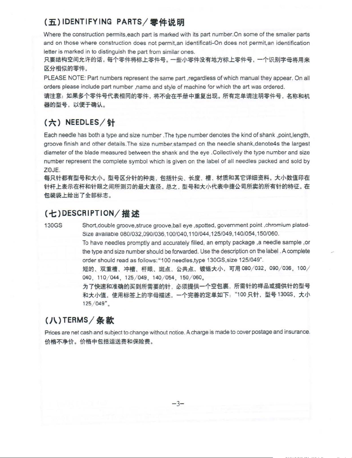
(-t;)DESCRIPTION /
130GS
(}\.)TERMS /
Prices are net cash and subject to change without notice. A charge is made to cover postage and insurance.
~~~~~.~~~§ffi~~~lO~~~
Short,double
Si
ze
available 080/032,090/036, 1 00/040,
To
have needles promptly and accurately filled, an empty package ,a needle sample ,
the type and size number should be forwarded. Use the description on the label . A complete
order should read
~tr.J.
~•"·
040, 110/ 044 , 125/
~7•~~*retr.J~~PJT~~tr.JH
fO=*:J)\ii
125/ 049" .
;lit
-~
groove,struce groove,ball eye ,spotted, government point ,chromium plated-
11
0/044,125/049,140/054 , 150/060 .
as
follows :
l!flM.
049,
.
{fJl.ltF~l:~-*-Htlii£
"1
00 needles,type 130GS,size 125/049".
ffP~.
tile.
~~.~-
140/ 054, 150/ 060 .
.
~~m•-1'~-E!•.PJT~H~~a•m•H~~~
.
-1'~~~~-~1':
.
•~*'J'
.
~m
oso;o32,
"1
00 R
it.
o9ofo3s,
~~
130GS. :k1j'
100
or
1
-3-
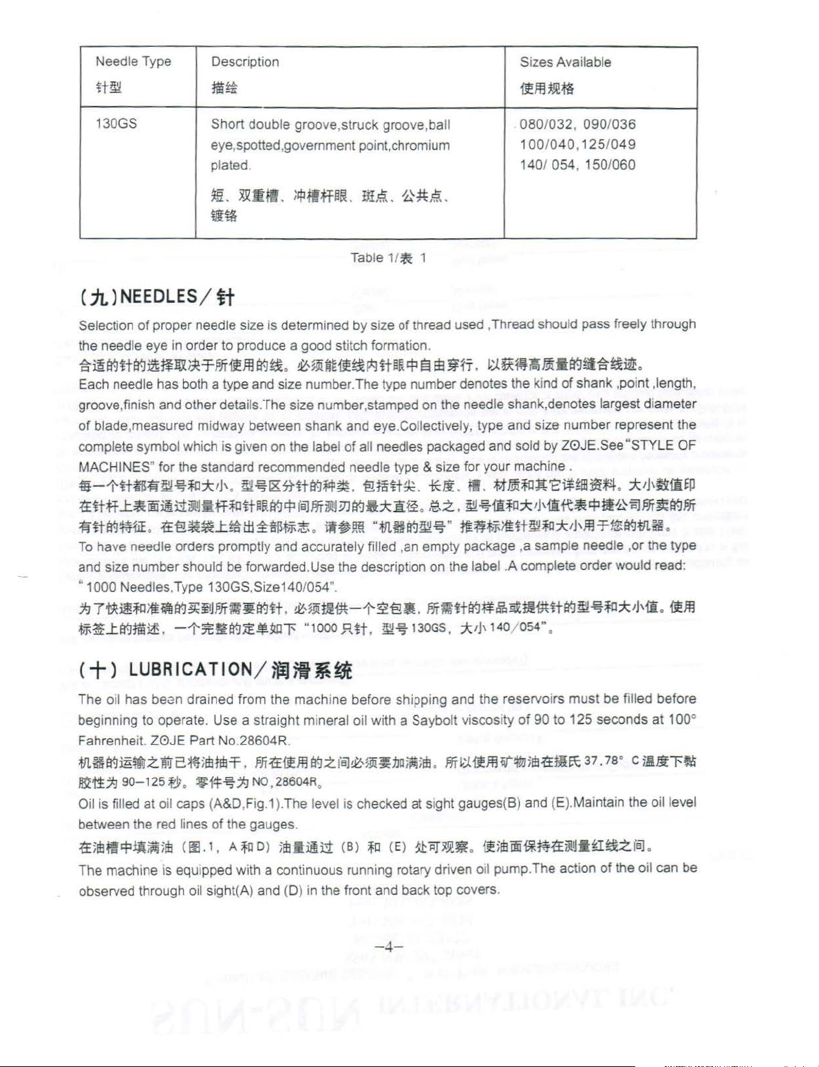
Needle Type
Description
Sizes Available
lt~
130GS
( iL)
NEEDLES
Selecti
on
of proper needle size is determined by size of thread used ,Thread should pass freely through
the needle eye
~~~lt~--~~~M'Ifm~~
Each needle has both a type and size number. The ty
groove,finish and other details. The si
of
blade,measu r
complete symbol whi
MACHINES" for the standard recommended needle type & size for your machine .
4it-1'fttrifl"~~~::k!J'
1£lttf
..t~iiD~~3'!
fllt~¥.HiE
To
have needle orders promptly and accurately filled ,
and size number should be forwarded.Use the description on the
" 1000 Needles,Type 130GS,Size140/054
.
1£'€!~~..t~lli~$~;t
~7•~~*~~~~PJT~~~lt
~~..ttt-.JJI~
.
m~
Short
double groove,struck groove,ba
eye,spotted,government point,chromium
plated. 140/ 054 , 150/
~-~mm
w~
/
tt
in
order to produce a good stitch formation.
ed
midway between shank and eye.Collectively, type and size number represent the
ch
is given on the label
.
1J
fitf~ltPR~~
-1-:lt~tt-.J:iE~~l'
.
;
IPiffHtL
.
~~•••~lt~~~~•fi
ze
number ,stamped on the needle shank,denotes largest diameter
~~1&5Httt-.J~~.
fBJPJTilj!
.
.
~~mm-t-2'€!•
"1000
itt~. 0~,~
1/
Table
of all
~
pe
needles packaged and sold by Z0JE.See "STYLE OF
'€!t!~t~.
~
3J
tt-.lft::k1if£
iW~!ffi
".
"
.fJl.Hif.J~-€5-
JUt
.
~~
tl
-
1
.
number denotes the ki
*li
.
fl
• .
~.z.. ~~1ft~::k,Haft~~i!0iSJPJT~~PJT
"
ffH~~~~H~~::k'J'm~1$tt-.ltll.H
an
empty package ,a sample needle ,or the type
label .A complete order would read:
.
m~H~~B•mmH~~~~*!J'mo•m
130GS,
:::bJ'
'!fffl~m
080/032, 090/036
100/040,125/049
~&~~-·~~~~•.
nd
of
.
Mmi~Jt'E:ltFm~~
140/ 054" .
060
shank ,point ,length,
.
::k!J,ti:ili~P
.
The o
il
has
bei3n
drained from the mach ine before sh
beginning to operate. Use a straight mineral oil with a Saybolt viscosity
Fahrenhei
.fllH~~t!trzlltr2*t
~1i;/;J
Oil is filled at o
between the red lines of the
1f5mf!~tJ~
The machine is equipped with a continuous running rotary driven o
observed through
t.
Z0JE
90-125
Part No.28604R.
5
1Mdl-=f
.
m1£•mtt-.~z
fJ;
o
*14~
il
caps (A&D,Fig.1
;
m
<
oo.
oil sight(A) and (D) in the front and back top covers.
1 •
~NO
ga
A~
o)
,
28604R.
).
The level1s checked
uges.
;m
f
BJ~,~!ii~no~;m
i!~
(B)
~
i;:>
ping and the reservoirs must be fill ed before
.
PJT~:J.1i.FJHit~;m1£NIE\:
at
sight gauges(B) and (E).Maintain the oil level
<E)
~
1iT~~JR
.
il5m®f*ffl1fiYltl•tl~z
il
pump. The action
-4-
of
90 to 125 seconds at 100°
37.
1a
· c
71!~1'~
fBJ
0
of
the oil can be

THREADING & OILING FOR PLAIN FEED
·li~M~R9·~R.iJtjfb
I
or
2 drops
or
oil twice o week
-
Jil~1!!1~/X
' I
I
\
""--
2 3 1
---
//
CI J
A Oil Fill Cop & Oil Sight
B Oil Lovel Goge
C Pump Primer Screws
0 Oil Fill Cop & Oil Sight
E Oil
level
Goge
FArm
Oil Drain Plug
G Looper Position Knob
/
J
(
I
I
""--
__
;::/
~illil
l!!!~*.;:p:~
ifil~!Si;IJit~~ItU"J
~fiji]'
;J1111*.if1.~
1-l~l!!!~
~tt:lEttt!~
\
FI
G.1
MINIMUM OIL LEVEL
.
1"'
at
I
I
MAXIMUM OIL LEVEL - -
~-
- 5-

TliREADING & OILING FOR DIFFERENTIAL FEED
-~~~fll.tf9J1tlR.~jJij
::x
2 drops
or
x
LNice
o
week
-JI~;}Ijjiij~
•
•
A
Oi
Fdl Cop & Oil Sight
B
Oi
Lovel Goge
C
?t.:mp
Primer Screws
:>
Oi
RIJ
Cop & Oil St
E
Oi
leve
l Goge
F Ami Oil Drain Plug
G Looper Positi
on
_j
,/
&
I '
(
I I
\ I
"'-.._
__
ght
Knob
s0,
)_
/
FIG.1
MINIMUM OIL LEVEL
.,J,;ma
MAXIMUM OIL LEVEL
il::*:illla
- 6-

mti~R7
w-~.f£~~1§-mB
When starting a new machine. beginning filling the reservoirs
that has been
screws(C).Apply oil to these holes and operate machine
.Replace screws(C
~~mMmHdmH~I-~~~J§-~A~ffl~~~~~~.~~~~~~-~~-
S*~~~~~fl(C
(C).
CAUTION:
~~=
Oil may be drained from the machine
and plug screw(G )at the back
~~fi~J.A.tJI.Htt-l~?~imHfi
~1¥-JJ§-W.
••
@ft··~~~~-.~~~-~.~~@~~~~~~82(A)~(D)-~~~~~
!
U.!.il.~
.
·i
dle for some time • it may be necessary to prime the pump.
).
l . .f±R~-~#A@.mBI~~-S~~~~~~~~~
If
oil does not bubble when machine is running , the circulating pump is inoperative.
~•~mH~H~~-~~~M•~•In
at
two places ,plug screw(F)Iocated in the bottom
of
the main frame below the handwheel.
. -~~!.!~~fl
(
F)
-E-TIEf!I¥-JJiUU~
of
when beginning to operate a machine
To
do this ,remove the two plug
until bubbling can be observed at the windows
-
~7-~I~.~
.
~-~-~~~fl
.
-
~~~$1fl
(G)
-=¥~1¥-J~W
of
the cylinder
.
.t.tJI.
<+-)
A convenient means for threading the looper has been provided. When loopers are at the left end of their
travel,press the knob(H,Fig.
the machine as illustrated in (Fig
flt.]j{l~Jr5!.f£f1ilit
~~3~B1fi7. ~Ill
<+=
NOTE : Instructions stating direction
relative to operator's position at the machine .The handwheel rotates counterclockwise
direction ; when viewed from the right end of machin
~=~M3m~~ma~&~~~~m•.M~M.J§-.~.S#A~ili-em~mH~~H~M~tt-Jm•
~~-~MmHtt-J~J§-wt~
<+=>
Torque specifications gives in this catalog are measured In inch-pounds or Newton-meters.AII straps and
eccentrics must be tightened to 19-21 in .l bs.(2.1-2.3Nm)Unless otherwise noted.AII nuts ,bolts ,screws,
etc,without torque specifications must be secured
torque specifications for connecting rods,links,screws etc
illJ:~t!Mt~~*~~ilitt-l~m~~'i"
L:t-·*)
!J'!i!'Jii~~~~rr$
THREADING
/
~ti
1)
and loopers will back out
.1
).After threading ,push loopers back into position.
.t~~. ~
<11!.1)
f1iltt~'8~~1¥-J!l~itl
PJT?f-.
~31~~1§-. tef1ilttfl~I*Ui
) ADJUSTING INSTRUCTI
of
location ,such a sright, left, front
.
-=¥~~¥-J~ff~~~~~n••
TORQUE
t:R~tl~.
REQUIREMENTS
·
~~.!:f::
~~1:1fa'8i)t.P.ij
.
~~~:•a-ei5lP.ij
.
~H!PJT1ftt-lil¢~.
.
~~m~m*~ti*T.
of
position,leaving them easily accessible . Thread
.
ti~OO~tit-'¥
ONS
/
~~i$tM
e.
·
/
tfl~~*
as
tightly as possible,unless otherwise noted.Special
..
are shown on the parts illustration
·*·
JiJT1f&:$~~1ia~L.'n~~m
t~tt
.
t~fl~if?.~,~~~
!1'.
(H.
Ill.
1 ) •
.
or
rear
19-21
S~n~.
~~"i*tt-llllir-.
f1iltt~lc:JJ§-8tfH~
of
machine .are given
~'i"·~
.
~-5i·~~iR~::k
,i
n operating
s.
(2.
1-3.2
C+
1m)
SYNCHRON
IZING
NEEDLE
AND
LOOPER
tt~~tta9fcl'!Vm~
- 7-
MOTIONS

NOTE: Needle and looper mechanisms are carefully synchronized with precision gauges before leaving
the factory to insure the best possible sewing conditions.
~=~7~~~~~~~••.m~~~r~Mm••~~~*••~~~~~.~ff~~ff~M~~~
~
.
Should it become necessary to disassemble the main shaft or
replace components of the needle or looper drive mechanisms,
FIG.2 (00
FIG.3 (III 3)
2)
re-synchronization
proper sewing adjustments. This is accomplished by means
an adjustable split coupling located beneath the rear top cover,
connecting
the looper mechanism.
~*~~m7f
the
~ff~rqff~~~tt
-~~~m~~mm~w~~~~-H.
m.
t::~rqnm~~~~~~•
To
synchronize the machine,remove the needles,presser foot ,
throat plate, feed dogs and upper feed roller mechanism.Rotate
handwheel in the operating direction
the bottom of its stroke and just begins its upward travel .Loosen
screw(A,Fig.2) and remove the looper for the
from the looper holder.lnsert a strai
9mm) or 11/64"(4.3mm) diameter by 2-1/2"(63.5mm) long into
looper holder
the rod (B) is at the extreme left and reinstall the throat plate.
Loosen screw(F)in looper holder and move the ho l
right
until the nght side of the rod is approximately 5/32"(4.0mm)
from the left edge
handwheel in
rod(B)comes
point,clamp
(D),flush against the underside of the machine casting(E).Rotate
handwheel in the opposite direction
contacts
clearance between gauge and casting
is .005"(
~7~ff~rqfi~~~M.~*ff
~"l!t~fJ1~.1Sm~l"1floJ$tM~~1U1Jffff~'2~~~T$Jtii~ii
i1Bt7:J.l1:
).Arq~tfi~~lfl.
~. *1l7:J63.5mmitt.A.rqit~tt:.§.m:~tt1\Hitr
~li~Jff
(F)
the edge
0.1
mm).
. t/l7Hitr (
(B)
jf:
.§.te!~
of
the machine will be required to facilitate
of
crankshaft to the main shaft, which in turn drives
::EffE!£~H§.trqH~~Mmf~~~IWt.
.
~-~~~~~~-~-~--.~~
~~Mm~::tffm•
.
until the needle
ght
steel rod (
and
retighten screw(A).Rotate the handwheel until
of
the throat plate,tighten screw(F).Tum the
the operating direction ,with needle
in
contact with the edge
lin
ing gauge No.TI147(C)around the needle
of
the
throat plate.Maximum
A,
lfl2)
fj)...][WJ~
of
the throat plate.At this
until needle
or
rod and throat plate
.
ff~.n•.mM~~~m
1f:.§.3Mrqff,
(B)
][@~
3.
.fffi1.iit!tf:.§.ff~lt•~.l1:.
loJti§.tloJ{i~Mli~Jff~;(:lit!~it•~
~~~Q
bar
is at
left hand needle
8)5
/32"(
3.
der
left or
bar
rising until
bar
bar
or
the rod
allowable
fflti~1Erqff
9mm
§!
4.3mm
(A).
:k
~M~
f'/l*rq~t~~tltJ
ti
it!:k~f.J
- 8-

4.0mm
TI147
mm~~ttfr~ttf&tr.:litltiH»;.t.J.ll:
~~fJJ.ft~~~~~~~~~im~~~~:
and set screws.
the coupling . The holes in the main shaft end of the coupling are larger than the diameter
permitting severa l degrees
snug the uppermost horizontal clamp screw enough to hold coupling (A.Fig.3)in position, If the handwheel
is turned in reverse
casting(E)before rod(B)contacts the edge
which was snug ,while holding the coupling
synchronization. If the handwheel is turned in reverse of operating direction and the rod contacts the
edge
turn the handwheel slightly in the operating direction.Use
clamp screws(B.Fig.3)securely,and recheck both clearance points with .005"0.1 mm)shim gauge
,
rt~!lfl
(C)
~.ftttfr
If
machine is not synchronized the following applies :
Both ends of the adjustable split coupling are secured to the crankshaft and main shaft by spot screws
Loosen the three horizontal
handwheel slightly
of
the throat plate before the clamp gauge contacts the machine casting ,adjust as before ,except
1 mm)exists between gauge and casting or between rod and throat plate ,in both the operating
reverse directi
no slippage occurred
~~~1lHtr.:J~~$m~un~~~un~~~m~±fr~1l$~
~~~=
~~itFaJ~
lf~:~Ulfl~$il~1lH
ll!.
Ul:ft!MmJt~t&fltrt~~~t'fl
FaJ~tt
mtr.J
it-t&~fBJtr.:lfBJI!Jit~Sl:.t
1mm
4'tlfl (B)
•
2)
~fJL~
.
~~~~$~ft~.&:JJicl$tiM
-~.
•·-~~~•••tr.J~icl~•
tr.:J~R~iJiH.iE1£rt~tlflm5.2:1i~~~~
(F
),
i
S~ffJ)jo)fdi~~~]i~Jfr
(D)
J!lmJ!H1J.~/iiim
.
On
the main shaft end
of
rotation in either directi
clamp screws(B,Fig.3).With rod (B.Fig.2)at its farthest position to the left ,
of
operating direction and gauge(C.Fig.2)on needle bar (D)contacts the mach ine
in
reverse
ons
of
.ftLHf7]<1JL~A.l:tr.:J.::.
of
operating direction,snug the uppermost horizontal clamp screw(B),recheck
the handwheel. When th s setting has been made ,tighten the three horizontal
whi
le
tightening the screws.
tr.:ltfllL'f:ilkl~L
o
-1'~-~fl
(A, ll!.3)
(E)
~1llUtff
0.
1mm
(B)
~tt-t&li!tlti~~
(C
).
.
~~~~$.
(E)
~ll:ft~f/l;te~fr~tt-t&tr.:Jit:kfti~
of
the coupling(A,Fig.3)three screws(B) thread horizontally through
of
in
±+f~tl~.l:tr.:l:tUt:tlflli~:k
(B.
:iE:Ul:
.
~~-=f~iS~~-T~.&:JJicl$t1H3.itff
~~$£~tr.J.&iaJ~$t
.
ff~it*itl~1l~~n+r~•a~m~tr.:J1l~~
.
~~~~.&••a-t
(B)
tliif!Jttf&tr.:litl!'l;.t.J.ll:. Jit!M
.if~T
•
.&:JJio:Jtdi~~~]lf!
on
to properly synchronize the needle and looper.
the throat plate loosen horizontal clamp screw(B.Fig.3)
place with
!113
). il+f (B,
t9~7]<~~Atlfl
.
an
Allen wrench
sh
im stock to insure no more than .005"(0.
.
~±fr~1lH<A.
.
llJ2
)
Ul:-Tii~li!
•
.ft£1f~~tr.:l*lf~Atlfl
.
rt~*lf~Aitl:imtr.:J~fl
.
m~R~s~~•H~m~~~~+r~
(B.
00.
.
:iEIM~
J
iU~NO.
Jl§
.ft1lttfJJ.~tr.:l.l:$~ti"fr
f
BJMi~
o.
1 mm.
of
the screws,
in
set screw(C).Rotate the
and
to
assure
~3>~$.l:tr.:J
fti!fB:-:JJiclifJJi:tr.:ltdt~il~~t
.
il~itr-Tii:f-5~tr.:l*
(D)
1:~~-H
(B,
Ill
3),
¥H~itll~~~
(B).
.
~~~..tw~
3).
#.§.~4'.~tr.:li8JI!Jli.
(C,
~IJT~i!f
m
0.
C+
.li.)TIGHTENING
When replacement of the needle bar, and
bar 14-16 in
the purpose
torque rod in the hole at the upper end
suitable
bend,the needle bar head has been threaded into the needle bar properly.
~~Jt;~itfr~it~IM
N0.21227ARtll~ff'2!!~fJJ.H!MiifHiHi~tr.:J
.lbs.(1.6-1
of
too
l,
turn the needle bar wi
.8Nm)
eliminating the possibility
,
NEEDLE
or
use torque rod No.21227AR that has been supplied
th
bUt~f!J~tfftr.:Jtll~;.t.J
HEAD/rtatt§k
or
needle head is necessary,torque the needle head to needle
of
distorting the needle bar due to overtightening. Insert the
of
the needle bar, while holding the need le bar head with a
the torque rod onto the needle bar head. When the rod starts to
1
4-16
.
,Eft-T
~"t · ~
i
ili~~-Ti:l:~ii'iiilitff~!Hitr.:li~m
- 9-
(
1.6-1
with the machine ,for
.8
t:f
· *)
~~ilm~~;.t.J
.
~J§~m~IA

Rtt~~~"~~~~•~w~n~mAmft~.mm•~••~~.~~*••~"·~~~•&•A
ttff
.
C+*)ALIGNING
tt~tt'-&.1:~1\..&l-B:t&
FIG.4
FIG.5
(00
(00
NEEDLES
4)
8
5)
IN
THROAT
Insert a new set
(B,Fig,4) slightly loosened,low
head as recuired until the needles are centered
plate needle hole slots . Tighten screw (B)torque to 19-21 in.
lbs.(2.1-2.4Nm).
1liU-...1Mt.
ff
(A)
jij
19-21
NOTE :
slots , the lower cylinder must be moved as stated below.
5:%:
~~at=1'~ttt&~~nfiX-1i:t£
2.~~~to*'J'
#S~~£31('~-tt~l[fijftift-Tltf&fL~tpJl,'jJJ.t.
~-t · ~
If
the needles can
PLATE
of
needles , type and size specified, with screw
(
2.1-2.4*
SLOTS
er
needle bar(A) and tum needle
in
.
~~f't}3H
not
be aligned
..
UJ
(B.IIJ.4),
· *>
~m~rt~UUJ
in
the throat plate
.
l'f11.~-;E1'£1'Wt&3i'JJ
the throat
~ifflt
(B).
7 .
C+-t)CENTERING
THE
CYLINDER
lE*'l.~~lt\
Remove the top front cover and gasket from the main frame.
Loosen cylinder holding screw(A,Fig.5).Turn eccentric screw
(B)clockwise
needles are centered in the needle holes.Tighten screws(A)
torque to 18 ft.lbs.and recheck settings.
~~m~
(A
.IJ].
~ttift-Tttt&n~rp~r.'
#
.§.JiiJT~~~gc
NOTE:The cylinder may not move freely when the eccentr
turned because the joint sealant compound has set.
ii::
~~~L.'$t~f;IJ"
a-tl'fJI.~~i!~!lt~~
or
counterclockwise to move the cylinder
<m~>
5)
.
~~m~~~m~*~
l®i"H~i$"ttJtffft'UiaJL'~n
.
mm~:tJ
.
.
~fJI.~iiJ!i~=1'~~~~3f;IJ
7!J.l!Hf'J
·~
*m~~~~~n
(B)
it.l:f11.~3f;IJ1!
1a~-t · ~~tt~t~n
<
is required, loosen screw (A,Fig.7) in looper holder,permitting
movement
dimension as shown in Fig .6.Retighten screw(A.Fig.7).Repeat
for other needles and loopers.
fi.APJf~~~~*'NfJilrtt
~~~tt. 3~ttW:Tjl1.£:illa:t.
tfJJ"Dt.am!ie3.
(C)
~~$j;'{!tf.Ji}IJ~
FIG.? (
Rotate handwheel
to touch but not deflect. This adjustment can be made by loosening screw{A.Fig. ?)in looper holder.
holder can be moved front to back to attain looper to needle setting.Aiways check the 9/64"(3.6mm)
looper gauge setting after setting the looper to the back
setting
of
the looper to the back
~~ft:n~•••~~~•~ttm~~~w~~tt-.Jttmm~m~•~~-
(A,
IE.
7)
tf.lt!}~*if.Jfl
tf.Jmi~~.
tt:E£sW:ll.iE~
The amount
the amount
contact the back
~tttr.l@l~lt
w 1 / 3
m
3.6mm~ttif.Jtift*~~
of
of
avoid it is recomended as a starting point ,to have the points
t:ar~i9:7-J
~
tfJ
~~~
7>1
00
7)
in
operating direction to assure that the looper point passes to the rear
of
.
~tt~~$1ltr~~M*R~~tt£~Jtttf.J~~iJU~
o
looper avo
of
~~
id
has been set at the factory to .110"(2.8mm).lf it becomes necessary to adjust
the lower 1/3 of the back
2.
Bmm
.
jzDW:~Jt;iJU~
,•:'Bltiltrrif.J
fl.
(A,
00.
ff.o
IHIT?9~~fl
the needle after setting the 9/64"(3.6mm)looper gauge.
o
#..Eim.&it?.
of
in
either
Smmo
fi}'ij~~j;J
7
).
ff -:1J
.
the looper blade.
@ill:.
icJtf.J~M~H*R~~fie~3.6mm,
(A.
of
the needle,and conversely,always check the
.{£~~~3.6mm~ttif.J~~~~~~.{£tt~tf.J~
t~t:r.¥m
B:tt~~~tt'Wimmtltttr.lffi:T~tt
direction
o
jzDW:if.Jfi~Jt;.
to
attain
I
-~stif.lfltiilltf.J~tt
fitt
NO.
21225-9164tfJ~ttif.Jflft
the 9/64"(
(B)
tf.Jtfl'L'~~tt
f'L}7f~tt~J:tfJ~fl
3.6mm)
(A.
fll,
6)
(
A)
jmi¥J.6Plf
007)
o
Jt~tf.J~tt~~tl11=£-.f$tf.l
of
the needle
o
~~~~~tt~tt~...ttt-.J~n
o .~d~:ttii.W~~tt~tt§im
of
the decending needles
o
looper
D'Jl'
<+it.)
:il.
NOTE:Whenever looper avoid is changed looper clearance to needle must also be reset.
~:
<=+)SETTING
The height
of
the looper, with the looper point even with the right side
SETTING
Coronec:t~.n;
Roc:t
O.f'erenta.
l!fifrt$JJ~~
3~tt@l~-~~§. ~tt~tttr.J~~~~-ENft
For
Feed
.· _ _
~~
FIG.8 (
of
the needle bar is correct when the top of
THE
'-'A
•
..
• j
-
00
8)
LOOPER(CONT) /
If
more or less looper avoid motion is required.remove cylinder
side cover(A,fig.8)1ocated
screwdriver to loosen looper avoid link ball joint(B).Moving ball
joint down
motlon ,moving it up acts the reverse.Retighten ball joint(B)
!
i
:~
·-·
securely.
~tt~u~~~~~~£~Jt;tt-.J.~""Fm~~imt£l'~tr.Jill~
(A . Ill.
~tt@l~J.i'~~ttl'~~@]~-~~.
~-~tf(2)
in
the lever slot increases the amount of looper avoid
B)
o
~iJ~JJtL}7f~tt@limf.1'~;fHI~tf.JJJ~~
(B).
o
HELGHT
OF
NEEDLE
the
BAR/\i.tttf-aJI
needle eye is 1/16"(1.6mm)below the underside
of
the needle
at
the lower front left side.Use a
jzDW:tt...t~~-~~~
.To
make adjustment loosen
-11-
(B)
.
fe!

TORQUE.
19-21
1n
l
bs
(2 1
-2.4Nn
)
W\
8
A
screw(A.Fig.9)and move needle bar (B)as required to attain
dimension.
s
H~tU91fftri1il~t~
it.!ili'ili.~
M~ff
NOTE: Care must be taken not to disturb the alignment
needles when moving the needle bar either up or down.
;1,
.iE
ila9. s~~if.l~M.
(B)
f!Jiilf~;j((f){ftii
,J,/L.,a93M~
1 .
Smm
a-t.
l!P~i1il~~1£~a9~ltl.
t'LHUJ.tr
.
~
~t1\~a9B:~11sitff
1:
CA.
!E.S)
1'3MM
~ff
#iH~
of
the
.
FIG.9 (
(=+-)SETTING
00
9)
THE
FEED
DOGS
FOR
PLAIN
FEED
-ii~M*JL~M>fa9~-
Assemble the main feed dog and throat plate.Main feed dog
(A.Fig.11 )at its highest position,should be set to project above
of
the throat plate,the depth
screw(B)and front support screw(C)should be set
this setting.
~~±l!*-1~ft1~t&
a-r.
m~ue~*4*~Htt&~j;f~-~~
(B)
~fiiW(fJ~JJ~tJ
The feed should be set
the front
throat plate when the feed dog is at its most forward travel, The
same amount of clearance should be between the back
feed dog and
the feed dog is at its most rearward
loosen screws
a
counterclockwise to obtain proper setting. Tighten screws (A and
B),reinstall plug screw(D).
s~~*1£~~~~~mwa-r
FIG.11
a9iiEY~Tl!~~~W~~tt&~f+:rt.~~W~f8Jlle:k'J'
-T~tr
B)
(
D)
*!H~llti~JI
,
~1\f~-T~tJ
(D).
.
fflU~JJJ®ia1HP11$M~~~~~L.'ft
t&~~:rt.fiiW~f8Jlleii
screw
of
the feed dog and the front
driver
.
.
±i!*-1* (
the
back
(A
and B,Fig.10)and remove plug screw(O).Using
turn
ili::tf'L}ff
its teeth.The feed dog mounting
A.
00.11 )
.
(C)
~~it-t,
so
there is equal clearance between
of
the feed slot in the throat plate when
eccentr
.
i!~•m~Ti!~~~mw~~
.
si!f+~1£~~tlla9-!l~itia1,
gc
~i.ltr
(C)
~jJ~f!Ji~ti§la<J
EY~$~~-1-i~~
of
the feed slot in the
travel.
To
ic
pin
(C)
(
A~B.
to
maintain
{ftf~'T~a9l1t~~
l!~*a<:Hiflt'n
.
of
the
atta
in
this setting
clockwise
or
l!MA
l!l.10
)
#.§.3M~
.
f?~~tr
(A~
( = + =>SETTING
THE
FEED
DOGS
FOR
DIFFERENTIAL
~rJJ~Mm~M>fa9~-
Before assembling the main and differential feed dogs,set the feed bar eccentric pin (A,Fig.1 OA)Iocated
in the left side near center
of
cylinder,so that the slot in the head is
in
a horizontal position. This assures
-12-
FEED

A
D•fferentral
FIG.10A
FIG.11A (l!fl lL.\)
(i!B
Feed
lOA
a neutra position
main and differential feed bars simultaneously.The feed
pin is retained in position by set screw(B).Assemble differential
feed dog (A,Fig.11 A),main feed dog(B) and throat
the main and differential feed dogs can be individually adjusted
to height.Main feed dog (B)at its highest position,should be set
project
to
adjustment is necessary loosen screw(D)and move feed dog
(B) up
)
should sLpport front
1£~f[]~JHJJ~*4~tr.J
1M)Q~~~~~J:m~~~~~~.~~M~~~M~~*
.ifLffi:.W
tF.lLffi:ii,
00.
ll
>ftr.J~
~.
3!0*i1U~~~.
&•rr~~~-~-.~M~tr.J~·~(C)$
mw
above
or
down to attain correct setting.Feed dog support(C)
.
~£7J
~t~tr
A)
i:~*4!}f
• •
i:i!M>f<B)~~fi-ffi:W".m~~--
.
of
eccentricity for the purpose tilting
the
throat
of
feed dog .
~
~iitr.
7~fll~HdJ~*4~!BJatf1§f~at,
(B)
ii~*4**tt~ift.
(B)
fCH-t&
tk7f~lr
plate,the
5tiJ:~*4*'J:~1fiijll,'§;t
.
~~ljif.Jfl~i!~~f[]
(D)
depth
#.ElJ:1'3fJJ~*4~
of
-f*iiE1fiij1L.'~~~
~~~fJJ~~>f
~
-1£~M~~
of
the
bar
plate ,Both
its
teeth.lf
(A,
00.
(A.
~fJJi! *4
-~>f
(B) ~
(=+=)SETTING
~i9J~Mm~~>Ftrn~
If adjustment is necessary loosen screw(E,Fig, 11A)in feed dog support(C) and move as required.Retighten
screw(E).The differential
loosen screw(F)and move feed dog up or down as required.Retighten screw(F).
j(Q*if.l~~~.
M~M~
ffl~M~M~. •fJfrt~t~tT
NOTE:Should the main feed dog require repositioni
rearward travel ,loosen set screw(C,Fig.10A)in main feed bar driving link(D),rotate main feed bar eccentric
driving stud(E)as required, Driving stud(E)has a thin hexagon head with cutouts on two
movement by tapping with a sharp pointed tool,when wrench21388AZ is not available.Whenever the
main feed
adjustment may be required.Retighten set screw(C). Position main feed dog support(C,Fig.11A)flush
against bottom of main feed dog (B ),tighten support screw(E)secLrely.
ii:
3lO*i:~M~1£icllitr~icJFo3Mat~~t&mtl"
J:~~~~fl
~~ti.Ai£M"~¥[§J..t,
~H$~~t,SI&fd.l*i~m'fi~~~~.
~M~tf:J~~~
faff~M~~f$~
(A)
RTtiE.ttt"~~i!M>f
bar
eccentric dnving stud position has been changed ,recheck
(C.
00
.lOA)
(
C.
00.
THE
fP.Pd
dog (A)may then be leveled with main feed dog (B
~~~;~(;ijjf~~~M-1fiijll,'~grJJtltt
s~
l1A)
FEED
(C)
(B)
(F).
21388AZt&ttt~1i~ii:!t~Mat.
liNJT~i!tittf:J-f,'iH?~I~:Jt~:ef~~iJUl
~~i!*'f~
DOGS
J:tr.J!2..~fl
1£!BJ
- :ifiiJ:.
FOR
~
c2>
(
E.~.l1A)
ng
due to contact with the throat plate in its forward
.
!i!lJ
DIFF
#.El~Jffi~*~TJJ.
3!0*if.l~~~.
~i!M~~I!iJT~t&
(E).
~~~IH&~tr.JI~~m~:Jt~M.
(B)
tr.J~im1f-¥.
f?$~~stlll
ERENTIAL
).
If
adjustment is necessary
!ti/Tf?~i_lfl
t41f~fl
rear
~jgfj)t~~
.
(E).
(F)
needle guard setting,
.
t41fi:i!~HHgM~
(
E)
1i:ifir?~~~Uifl
FEED ( CONT)
#.El~~~*n
of
the flats allowing
:fir-~iiit~IT/,~
(E).~
or
(D)
~l!f;£~
(C).
:£
-13-

(=+1m)
NOTE: If plug screw(A) is replaced with a
Any stitch length change,requires resetting the needle guard.
it
:
jU]=*~~...t#TI¥J:*:~-T~JlJ
ffffl~~"*~l¥1~~m~*~m~~~~~~~I
CAUTION:When making stitch length adjustment
due to possible part damage.
CHANGING
FIG.12 (
00
1
2)
STITCH
When cha'lge in stitch length is required,remove farge plug
screw(A,Fig.12).Loosen feed rocker driving link screw(B)in fever
(C).
l
(A
).
9}1J~ll$lf~...tiia!ijH!iii1it
LENGTH
Moving
engthens
Retighten link screw(B)securely and replace plug screw(A).
s~*~~tit~"*oca-t
r.ifim
/
it~ti~*Jl
the feed rocker driving fink up in the lever slot
the stitch ,
(C)
...ti¥J1iU~~Jt~gfif.J~t~lJ
~.lt~fif.l~mn~~•fif.l~~~"*~•"*·&z~•.••~*
~...t!¥JSllJ
new
plug screw ,it shou ld be sealed with a silicone seal.
(B)
#iH~...t:*:a-TillJ
.
do not
exceed maximum recommended stitch length
mov
ing
it
down ,
.
37f*•.:rt~n
.
shortens
cA.II!.12)
(B).
(A
).
the stitch ,
.
f'J}fftt
if.lfimM'P~l!~
v1S':
*~••~Fc•fif.l•~~•
-ifl~mi¥Joof}}M~~~tl:ltiM
CAUTION:If stitch length is changed,needle guard must be reset.
w•:jz0•~~*•~~7.
NOTE:When insta
loosen screw(N,Fig.15)in needle head and rotate needle to attain adjustment(D,Fig.13).
it:
}t~l]Plf~;j(ag~I¥J
3~~*1i~fjgifolflilJfti!fi¥JB::*:tit~*Lta-t
C=+.li)SETTING
D
FIG.13 (
$:RI¥Jtta-¥~1'rl!*4P~PJr1£1¥J1l~
00
lli
ng
.
(0 , 11}.13).
READ
13
)
.
a~i'iJtm~tr..J$:R~•
Hl¥l•ifl••~~~~~~
the needle 1t should be parallel with the eye
NEEDLE
Set the rear r.eedle guard(A.Fig.13)horizontally
contacts needles(B)when
adjustment is necessary loosen screw(E)and move guard front
B to back as required. It should be set vertica
yet have its guarding surface in contact with the needles until
the points
the right side of the needles.
screw(F)and move guard and holder up or down as required.
$:~~!r.JFcWJ.I<.if~I
~~ltJlJf~ft~~MilJ~
.
jz[]=*~~~~f'J}ff~li
.
jz[]·~£il!lr.t
.
911Ji'iJtm£EBr*f~~*
7 .
GUARD/ii·tf~Ji§'-tp5t.
at
its extreme forward position.
ll
y as low as possible,
of
the loopers(C),moving to the right,are even with
If adjustment is necessary loosen
(
A.~.
13)
3'81£iliiliii!r.JW:Iilt-t
(B) 0
jz[]=*~~Jnijf'J}fftlll'
.
m•3~~~cc>~~•fif.la-t.~•i£~1¥l~~.
(F)
#..El~.!ffi~31<...tl'8fif.J·:f?~-~'8!r.J~
.
in
li
n~
of
feed.lf adjustment is necessary,
.
f'J}fftt~...ti¥JiJ.lJ
(N. !11.15)
so
that it barely
lf
I
fl
(E) I
~!m£
.
#..El!tE~tt~
-14-

(=+*>PRESSER
FOOT AND
PRESSER
ffi-~ffii1Jtftro~•
or
8
FIG.14 (
FIG.15 (
Set upper stop collar(K)to contact casting,so the bottom
foot do not touch,at the bottom
00
00
14)
15)
of
the needle stroke when lifting foot. Tighten screw(C) .
Adjusting
Remove presser bar
screw(A,Fig.15)on presser bar guide(B ).Loosen screws(C)in
upper collar and screws(D) in needle lever thread pull-off lever
Slide Presser bar upward high enough
yoke(E)with foot attached and tighten screw(F)
bar.Positi
with the holes in the throat plate. Tighten screw (A).
if.l!ht~~ffi~:
31fffi~jt~
~~n
~IJ;fF
J:~tlfl
( E )
.{£
t~fi.ffiM.Il.l.~ttn!3tH&J:~n.o.t
Presser foot guide plates(G,.Fig.15)should be set so that entire
presser
with no
ffllt.llsl~±~
~~.fflt.l.~~~..t~3IJJ~~~~~3IJJ
With foot proper
guide(B,Fig.15)securely fastened to presser bar,adjust both
guide plates(G)to obtain above setting. Tighten four screws(H).
l!lBG-ffiB!Il.!:ittt&~~~.o.t-Jiti
.ffittrie~$00,
rr~~mt-ttn
Reinsta
foot resti
l!:ii#
ffllt4ltt.ff~H.&..t
Replacing Presser Foot:
on
foot so that the needle hol
C
A.
!i1
lt
.l.
EHtHJt
foot
and bar assembly has free movement up and down
left to right movement .
<G.~.
ll
presser bar spring(B,Fig.14)and knob(A),with presser
ng
on
BAR
(B,
. 15).
(D)
.
ffi.ft14J~J:iif~
iJJ
I fT $
1s>
ly ali
if.Jfl~i's[~i}C
<H
>.
throat plate.
I
of
the needle head and the top
ADJUSTMENT
leaf
spring(B,Fig.14)and
to
es
lf!.14
)
~~~Q;
tLHfJ:W~fi14=..t~i.ln
.ffi
;fF
~~~~;t)
gned on throat plate and presser
ffi~.ffi;fF5!j1jf(B.
(B),
ftHfSI~.ffi;fF
.fE.$~iffi
iii
...1:
-
.
'l!.ffi!*.lls
(G)
J.iil:ffi.ft14JJ:~.ffiJ!141~
~tifT
1H&. rr~~n
7fi~t-
~~fi.t..titi8i!:St~~~
~.
nut
(B).Loosen
..
slip on presser foot
on flat
of
presser
in the foot line up
(B)
..t
c
c>
~13tr&m
(F) 0
00
~.ffi!!ll
ffiM.Il!3ffM.IlfF~~
.
l
~~
(8 . 11!.15) !3
14
)f[liJ~tL-¥
of
the presser
c A
>.
(A)
~
UL
bar
.
0
~-..t~IJJ~CK>~mti~~
m~.
rr:~un
The presser foot should be adjusted to be 1/8"(3.17mm)above the throat plate before the feed roller
mechanism begins to rise
guide as required to attain the specified point at whi
and maintain needle settings .
.ff~~~m~1f9ii...1:7tiWffiB!IIE~R~~tttt&~
15).
~!ffi~;}(7t~~~flisl~~ii~fti1JJ!*4i9-~F9ii...l:7t~11~1'Ul:il
cc>.
.
~ffillt.IJ&&H
..
Loosen screw(A,Fig, 15)
.
3.17mm.
fifi~BS!3X~~.~tt~~--~.ffillt4J~M$~~
in
presser bar lifter and guide (B),raise
ch
the feed roller begins to rise .Retighten screw(A)
fl}1f.ffifFti7tftl51~14=
-15-
.
rr:itlfl
or
CB
>
...l:~~n
(A)
#..El~R$tt
lower
CA. 00.
.

NOTE : There should be a minimum 1/32"(0.8mm) clearance between screw (M,Fig.15)and the bottom
of
the slot in link(J).
Regulate the pressure on the presser foot by turning the presser spring regulating knob(A,Fig.14) located
of
on top
To
Needle lever thread pu
foot is resting on throat plate.
it:
i!l1:ME~.ffiffSfffNi..ttr..l~IIP!
3fJJIXJIJ;ttr..J.ffi~~~~lT
3
IfMIJ~.ffitt&J:If.t
(=
~~~~tY$tf!Jfe~..ttr..Jif7W~l':
te~TJJ~n
Jm.AJW~~fJJtYte
~ZfBJ~J\i!fft&te
i±~itl
~.-
#..Eltr~Ufl
pressure foot spring (
remove just the presser foot, remove screws (l ,Fig.15) and replace foot, retighten screws (l ).
ll
-off(P) should be set 1/16(1.6mm)above bottom
illY (
M.III
.15)
Ej)!1f~tr..!JlHL
(
.
~~~.lH~ltiJ~
+-i:)UPPER
<
.
fittfl
<E> m~
FIG.16 (
A.
.
(H).
00
oo
1s
)
~~1£i!fft&~~
(E)
**~i*tit
(F)
(G)
<1!*4t&$U~!IaiE~71.iioJJ:£19)
~~t!T$ttr.Jt£ii1!:ff~~wtr.Jt£ii1m~
B).
(J
)
tr..!llitNBJil*@;fJO.Smm
(
A.IIl.
14 )
~~ffiM4!~1Jo~3
L.!fl
.15)
jt:.§.J!t~.ffiM.P.
( P)
Ji!Z
tt~ 0 Jfiiiitr..JR.~
FEED
16)
ROLLER
Assembly of Roller to Roller Yoke :
Assemble
Place woodruff key(
dr
ive gear (E)on to shaft {D),make sure key(C)goes into slot in
gear
between
assembled components through frame. Make sure that shoulder
of roll
direction on
shoulder of shaft( D) against face of gear(E),make sure
of
is against right (inside) face
of
roller is against face of
shaft (D) and tighten screw(H).
<B> ..t.
(C)
iltA~~fJJtS"fe
1fi
.
te!~~tS"~ff
of
slot in cover (Q)when presser
.
tr..J.ffiJJ
.
IiJfrt~tlfl
ADJUSTMENT/
dr
iven
gear
(E).While holding feed roller frame (B)with steel roller(F)
tt"le
two
er
(F)is to the ri
roller )on the flat
tef.mlff~m
(E)
1¥-Jtittl*
(D)
~~~~~Hq:tll\li*
~ff
(
E)
<
1£~w~~i21m~
{L).
1 .
6mm
.
..t~MtS~tJ9~-
(A, Fig.16)through feed roller frame {B).
C) into slot
frame l
obs
ght
gear
cc>
fi5lf!Jj!f:tteff
·
a93Fimfit-~F
of
feed roller shaft (O).Siide
, sli
de
feed roller shaft(O) and
.Align screw (G) (first in
of
shaft (E).At the same time thrust
(E),make sure left edge
of
left lob .Secure screw(G) on flat
<D>
tr..Jt~M*
1£~~~-tatel¥1~
·
~~lf.ti!.Fkt!i~I¥-J~i:i'
.
IEJif.trt~ff
>.
¥r$ff
<D>
operat
(
B)
..ti¥-J"M
(D)
tr.J~i:i'Ej
..t
a9t~n
ing
left edge
of
roller
·
ff <D>
-t~
(F)
1b.
<G>
(=+)\.)UPPER
..t~MtS~tR:R•c
When feed roller mechanism (C,Fig.17) has been removed or replaced,.003
(0.13mm) maximum clearance should be maintained between roller and throat plate.
3i!fft!T$tfil.~
(
C.I!I
FEED
. 7)
3fJJ79!J!~
ROLLER
71f-t
ADJUSTMENT ( CONT)
2 >
.
Ji!Z~f.¥w~~tt.t&ff:JifV
13mm.
-
16-
ft(
0.08mm) minimum to
N
BJ~;f)o.osmm~•*
.oos
f
8J~=*.J
a
o.
 Loading...