

Page 1

358000NU
35800DRU
m
35800PZ
358000WW
35800DZ
HIGH SPEED
il
m
JACKET
il
SEWING MACHINE
aJJ
OPERATION
PARTS
Ul~·UlJI~il~?lliliRD2ffi~BH~EI
ZOJE
SEWING
MANUAL
BOOK
MACHINE
CO
.. L
TO
.
Page 2

SAFFTY RULES
1.
Before putting the machines described in this manual into service, carefully read the instructions. The
starting
2.
3.
4. All safety devices must be in positi
5. Wear safety
6.
7. The warning hints in the instructions are marked with one
of
each machine is only permitted after taking notice of the instructions and by qualified operator
IMPORTANT! Before putting the machine into service,also read the safety rules and instructions from
the motor
Observe the national safety rules valid for your country.
The
until it has been ascertained that the sewing units which these sewing machines will be built into,have
conformed with the
the machine without the appertaining safety devices is prohibited.
In
case
and changes are made
supplier.
sew
ing machines described in this instruc:ion manual are prohibited from being put into service
EC Counc
glasses.
of
machine conversions and changes
il
Directives (89/3
at
your own risk.
92/EEC,Annex
on
when the machine is ready for word
all
valid safety rules must be considered. Conversions
11 B).
of
these two symbols:
or
in operation.Operation
s.
of
8. When doing the following the machine has to
ma
in switch
8.1
When threading needle(s),looper,spreader etc.
8.2 When
needle guard,folder,fabric guide etc.
8.3 When
8.4 When doing maintenance work.
8.5 When using
9. Maintenance ,repair and conversion work (see item 8)mu
special skilled personnel under consideration
10.
Any
work on the electrical equipment must be done by an electrician
of
special skilled personnel.
11. Work
described in the
12. Before doing maintenance
disconnected from the compressed air supp
disconnecting form compressed air supply (l,e.pneumatic equipment wi
to be removed by
or
by pulling out the main plug:
replacing any parts such as needle(s), presser foot. throat plate, looper, spreader, feed dog,
leaving the workplace and when the workplace is unattended .
clut
ch
motors without actuation lock,wait until the motor is stopped totally.
on
parts and equi
applicable sections
pment
bleeding.
under electrical
of
and
repair work
be
disconnected from the power supply by turning off the
st
be
done
of
the instructions.
power
standard sheet DIN VDE 0105 .
on
ly.
is
not
permitted. Permissible exceptions are
the pneumatic
In
case
of existi
only by trained technicians or
or
under direction and supervisi
equipment
ng
, the machine has to
residual a
th
ir
air tank
pressure,
),
the pressure has
on
be
after
I
Page 3

1. ffffltlltiz1ltr.
~~lffffl.fllnz1ltr.
2.
~*~~:tc~~Yl
3.
J!tijtii}}~~JiJT~&~J~~W.fJl.
flfg.fll§.Ritifiitffl.
~~, 9l1Ji~P}}~-tfl.fi~£litffl.fllti
4.
JiJT~~:tc~~-~~iPol~JlE?i1&f}i:Jl
5.
~i:Plll
6.
JiJTfif-tfl.fi:1Jiti~~jlt~~~tf.~i:~!l!IJ.
7.
~i2fif1m"F~f1!:
8.
t11Jr~:rr~if~
8.1
~~~
8.2
~f4=1f.t.
8.3
~7f$f8]§!$
8.4
~~H~m
8.5
~~~a~~~~~1tJ~idlzFo
9.
~~U~&f!J!liff&::'~fE~~~lt*.A.~i'£~~7tiffi~PJ)zFojzt~f
~fHI!lOO~J!ti~P}}
.
fitg.flliHC,~i'f~~~ff.A.~fHI!l~il*i~PJ)zl§;tt!MiAff.ffl
~~~~~~m~~~~~
iJ.
£,~1f~fiJ
EC.fllt~i.AiiEzl§:t~MAf!Jf.l
litffl~fJI.fii'fJti~P}}·1Lt~
.
.
~J§:t~7f~mif
.
~!l!IJ.I§~~H~
.
.
a
£,~tJJ~~i]j§!=if*~~**
gq:tmtt
lf.1
.
~ff&ll
.
f
8]7t.A.If.t
.
.
ttt& .
Ji~H. ~*43f. t?tt~:a
.
:
.
"STYLES
OF
MACHINES
.
~ititii~hlff
.
.
.
fJTDH
(
~~~ 8 ~
.
(89/
392/EEC, 1!#1.Jo
"
~~
.
1m~i~~~l:7CJ!t
.
~~~loJR~
).
.
118)
.
10.
JiJTfif.E3~-T~Ifif*rt-li
11.
~Jl1£~1Jl'liHY.J.gc#~i..Q:.l:Iff
12.1f$~~i*~~ffi~•zntr.
if~~IE~i:t~~iJII~(fJ.A.*iMl"
.
M<7i'ff;f-/t~~
£,~tJJtmffi~~'f;t;(f)i3tm.
.
DIN VDE 0105
~~l±l~'f;t;~~~fifJtJ~~ffit¥.ff
tiJtflf!Jtt-.J~ffl$*
.
.
II
Page 4
Contents
1
t'lni~PJJ
2
f4!~m~
3
fll.H~-5
4
~'{9
5
-'Jf!fi~P}J
6
it .............
1 m~ ..................
8
*li:
9
}t
.......................
10
)ii]iff~!ft
11
3f~
12
~~i~II}J
13m~~*·
14
tt~~}ttr..J
15
l9~tt~
16
lt~ltt&l:tr..l1L.sl-i:~
17
~tJ.;cc:p,c.,
18
~~~lt
19
~~~lf(2
20
i~ii}tff~nt
21
H~~tl.~~~tr..J~~
24
~~~~~nr
25
i~•ittf.J~-f¥j}'l~JI
26
.ffiM41~
27
...1:~~-®~tt-.J~~
28
...1:
~*4-®~tr..J~~
29
~~H
30
~f;fjt£~J
........
. . .
...........
......................
......................
1]
..
....
.. .... ........
......................
.. ..
....
· ....
.....................
.....................
.........................
.....................
....................
f.ilnM
..
;',
.... .. .
..............
)
..................
.................
.......
Inllfftf.Ji,ijj
.......................
.......
...........
:·
................
........
.....
......
!&
...........
.............
(
2)
..........
.............
1
1
1
2
CLASS DESCRIPTON ............................................ 1
1
3 STYLE OF MACHINES ........................................... 1
......
2
4 ILLUSTRATIONS ..................................................... 2
3
5 IDENTIFYING PARTS ............................................. 3
.......
...... ..
.......
.......
......
..
...
....
10
10
10
11
11
. 12
3
6 NEEDLES ................................................................. 3
3
7DESCRIPTION .......................................................... 3
3
8 TERMS ..................................................................... 3
4
9 NEEDLES ............................................................... 4
4
10 LUBRICATION ................... .................................... 4
7
11
7
12 ADJUSTING INSTRUCTIONS ............................... ?
7
13 TORQUE REQUIREMENTS ................................. ?
1
14
MOTIONS .................................................................... ?
9
15 TIGHTENING NEEDLE HEAD ................. ............. 9
16
SLOTS ................................................................ 10
17 CENTERING THE CYLINDER ......................... 10
18 SETTING THE LOOPER ................................ 1 0
19 SETTING THE LOOPER(CONT) .....................
20 SETTING
21
........................................................................... 12
22
FEED
23
FEED(CONT) ...................................................... 13
..... 14 24 CHANGING ST ITCH LENGTH ........................
.....
14 25 SWTTING READ NEEDLE GUARD .................
1 5
16
16 28 UPPER FEED ROLLER ADJUSTMENT(CONT) ..
17
1 s
26
ADJUSTMENT
27 UPPER FEED ROLLER ADJUSTMENT. .........
...........................................................................
29 THREAD TENSION AND RELEASE ................
30 DIFFERENTIAL CONTROL ............................. 18
IDENTIFICATION OF MACHINES ........................... 1
THREADING .......................................................
SYNCHRONIZING
ALIGNING
SETTING THE FEED DOGS FOR PLAIN FEED .
SETTING THE FEED DOGS FOR DIFFERENTIAL
................................................................
SETTING THE FEED DOGS FOR DIFFERENTIAL
PRESSER
NEEDLES
HELGHT
FOOT
........... ............ ............................
NEEDLE
IN
OF
NEEDLE ....................
AND
AND
THROAT
PRESSER
LOOPER
..
PLATE
11
11
12
14
14
BAR
15
16
16
17
?
m
Page 5
31
je~~t~H~
32
r.g~t~t~~~
33
~~1fi~H
34
~mitt~
~ft!~.
~
ilf~H.
~
iiTAH
~
RTlPfft~~i~
9~flt&.
..............................
..............................
.
..............................
~-~--H~.
#
..............................
fi~~~~.
1t~~i'W~#
~i'W~~~.~~~~.~i'W~~ffl.J:
tr..J~~'L'H~#
•~~~m..ttr.J~~~zwm#,r.gn
~zwmi~~r.gn
~zwl!~m..t~r.gH.
~:m~i~~r.gH~iJ:m
i4
..............................
..tmM
$1~
~m•.~mm.~~H&~~H~M
tl..ft.J
~~fie#
~~
•.
...........................
...........................
..............
jl{jf*,
......
J:~~t&
.................
...................
if
...................
lj\1{,
~i'W~~ffl.tr..Jfll;!el.i~*t
fiil~~flltr..ltl.;!Cl.i~M
....................
~~~~ffl.J:tr..J~~~
.....
..................
fflffi~~H~~~~-~
......................
........
.........
~~l.it&~*t
~m•~~-~~
········ .......
............
r.gn~~.
..
............
......
...
1s
18
19
19
20
24
28
32
36
38
40
44
l!~
48
50
54
58
60
....
62
31
FRAr.JE EYELET.. ................................................. 18
32
33 FOLDER ADJUSTMENT.. .................................
34 AIR
MAIN
MISCELLANEOUS
FOLDER, CYLINDER COVERS AND BUSHINGS FOR
DIFFERENTIAL
FOLDER,CYLINDER COVERS AND BUSHINGS FOR
PLAIN
DETACHABLE
OILING ,NEEDLE
SHAFT PARTS
PLAIN
COMPONENTS FOR PLAIN FEED .................... .... 38
DIFFERENTI
ECCENTR
FEED
COMPONENTS
LOOPERS,LOOPER
AND
FE
ED
UPPER ROLLER FEED,FOOT LIFTER AND THREAD
TENSION PARTS .................................................. 50
PULLY,CRANKSHAFT,CLUTCH AND CLUTCH DRIVING
MECHANISM
SEWING PARTS .................................................... 58
THREAD STAND .................................................... 60
ACCESSORIES ...................................................... 62
SETTING
LOOPER THREAD TAKE-UP ADJUSTMENT.. ... 18
BLOWER
FRAME,CAST-OFF
FEED ........................................................... 28
FEED
AL
IC
ASSEMBLY
DRIVE
LOO
PER
.............................................. ........................ 48
NEEDLE
TUBE ADJUSTMENT.. ................ 19
COVERS
FEED ........................................... 24
HEAD ASSEMBLY .......................... 32
LEVER,CRANKSHAFT
........................................................ 36
BAR,FEED
FEED
COMPONENTS,LOOPER
AND
LOOPERS
HOLDERS,FEED DRIVE \;OMPONENTS
AVOID
....
COMPONENTS
.......................................................
THREAD
BAR,MA
FOR
DIFFERENTIAL
TAKE-UP
PLATE,EYELETS
AND BUSHINGS ...... 20
AND
MAIN
LIFT&FE
IN
FEED
FOR
ED
DRIVE
BAR,FEED
FEED
...... .40
DRIVE
PLAIN
FEED
.......
FOR DIFFERENTIAL
AND
19
,
LIFT
44
54
IV
Page 6

(-)
IDENTIFICATION OF MACHINES/
*11.ii'Uta})
Each machine is identified by a style number which is stamped into the style plate affixed to the middle
the machine under the tension assembly.
The serial number is stamped
•8~mm$•~~
.~~-~~~<*~·•••~~~~
-~~a••~~ama~~~w~
(
=)
CLASS
High speed,Feed-off-The-Arm High Throw Machines,Two and Three Needle,Left Needle In Front.Light
Weight Presser Bar Mechanism,Adjustable Looper Avoid,Space In Front
Disc Looper Thread Take-up,Automatic Enclosed Type Oiling System and Filter Type Oil Pump, Visual
Sight Oil Action and Supply Gauges.
~ii.
ilim~~tJL~••
~~;.tJ
(=)
35800DNU DOUBLE LAP SEAM .Three needle, high capacity ,differential feed with upper driven
8" (203.2mm)
STYLE
DESCR I PTON
--~jt~&tt•.
OF
roller feed (.468WIDE).-Typical Application-For
garments.Seam Specification 401 LSC-3.Standard gauge Numbers
(9/64",3.6mm).Recommend needle 130GS,size 140/054.Maximum recommended speed
4500R.P.M ... 094 step sewing parts. 468(15/32,11.9mm)narrow roller.
~~·~~S".
-$ift~~-,EfFH:il~!$*4£(.J~ff!li~.
2mm)
f09
P .M···094
in
the casting at the right rear base
of the machine.
~~
>~•~~mtt••~M
.
/
fstl
~-~
.
jJijjt~=-
jt.
lt:iti~ttawrw
~i';IJ
I~H*~~IB-~Uo~~~~IB*·
.
~~.ffi*tm~.
MACHINES/*11,8B::I.~
in
and out seaming
:=_jt,
~ti~~.
(9/
64",
3.6mm)
!V~i2f.
~;.t]
~i';IJJ!~S3
. jlf¥ff,Eij 130GS,
468 (15/ 32, 11. 9mm)
~
W~~~t&~~i';IJ*~~
~.g-~~401LSC-3
j:
Jj\;.t}
140/054~tf.lll:*:5ti!f~Ji4500A.
~~~~tS$t
ama~~
of
Needles8"{203.2mm),Single
iPol!f~ttifii!:~•.
t!t~iif~51Bil~51Bil~.
on
heavy weight denim
8(1
/8",3.2mm) and 9
<~
••
.liALil2:!:f!8 (1/ 8
.
jt~litrw
$t~~;.tJ
of
.
468).
",
3.
.
35800DZ
35800DRU DOUBLE LAP SEAM.Three needle,high capacity,plain feed,upper feed,upperdriven,
35800PZ
Same as 35800DNU except with reverse teeth roller.
l!;t-7~~1Jjc]~
rollerfeed,FeedDogshave higher teeth on front.-Typical Application-For seat seaming,in
and out seams
3,Standard gauge Numbers
130GS.size 140/054.Maximum recommended speed 4500R.P.M ... 094 step sewing parts ...
468(15/32.11.9mm) narrow roller.
~~-~~~.:=.n.•ttn.~~mM.
-~f.l~~~Hf.
~S'~t!401
j:1j\;.t} 140/ 054
9mm
)
~~~~.
Same as 35800DRU except with reverse teeth roller.
~7~M1Jic1~
35800DNU
on
medium to heavy weight denim garments.Seam Specifications
tf!&Jt~-~
8(1
/8",3.2mm)and 9(9/64 ",3.6mm),Recommended needle
.
S3~w~mMc~•M~M.~~M•~•w
-$ ~~~
LSC-3
.•
~jt. fl:*:]ti!f~J.i;.t)
35800DNU
-ma~'!-T~tU13~ft
li£.Jil2:!:f!8
tf!<~-~
( 1 /
8",
4500R.P .M
.
3.
2mm)
.
1£~~~t.ttiM'tl~Vft~llit:ffHU~.
llJ
9 (9/ 64
..
·094
!V~i2t. ~;.t]
",
3.
401
6).
jlf¥'{f,Eij 1 30GS,
468 (15/ 32, 11.
LSC-
- l-
Page 7

35800DWW DOUBLE LAP SEAM.Three needle ,high capacity ,differential feed,high lift feed eccentric,
upper drivun ,roll
with
Typical Application-For use on heavy weight denim garments.Seam
3,Standard gauge Numbe rs 8(1/8",3.2mm) and 9(9/64",3.6mm).Recommended needle
130GS,size 140/054.Maximum recommended speed 4500R.P.M ... 094 step sewing parts
558(9/16
~m~~~~.~H.att~.~~~M.~m*~"•~~m•. ~~oo~~M•~•
~~Mc~•~)o~~~~M~~mw~Mo-$~~~-mr~~~Mm~~~~~ff
~i~. ~~~~401LSC-3, .tF/llt.fl~!¥8
f!ii!,Eij
14mm
",
14mm)wide roller.
130GS
I :;klj\;t) 1
)
~~M-~
er
feed (wide roller
).
Fee-ds have hi
gher
(1/ 8" I 3.2mm)
40/054~if 0 B~fti~~]i4500R.
.
p.
M.
teeth on front
Specmcations
~Q
9 (9/64". 3.6mm
094~~i21!···558"
of
feeds.-
401
). m
(9/16".
LSC-
..
(1m)
This manual has been arranged to simplify ordering repair parts. Exploded views
the mechanism are shown so t
page opposite the illustration
the number
~-~~-~7••*#~nnom~~•m~•*e~BBffllli*
-~~~~~-#~#~.~&·~~-~~~~~
Numbers in the first column are reference numbers only ,and merely indicate the position
the illustration.The reference number should never be used in ordering parts. Always use
listed in the second co lumn.
~-~F*:l~~~&~~~.
Component parts or sub-assemblies which can be furnished for repairs are indicated by indenting their
descriptions under the description of the main sub-assembly.As an example refer to the foll
m.stMB(f)$i!f(f)i.$iPJL~1£::E
1
11
It will be noted in the previous example that the cam follower ,bushing and cam gui
looper drive shaft
recommended ,so the complete upper looper,drive shaft assembly should be ordered.
~'-'-1-*i*:::f'~£~
Rlmfl~tlH*
When a part is common to a
description.However,when the
mentioned in the description and ,
•M*-~$#~~WMH*8W.m~~W::f5&~a~m·~~
ILLUSTRATIONS/~
of
pieces required in the particular view being shown.
1&:lt'91Jlli~i*~~~trrw
9 A3588-314 Gasket!
0 A3588 -373 Screw/ tilT
A3588-082
Top
are no t listed.
~~m
Cover,fron
.
Rfit!!mi*·
·
ll
iJ!J
of
var
ious sections of
hat
the parts
will be found a listing
~m~
Sf*
.......................
...........................
tl
m1Di~
The
machines covered in this manual,no specific usage will be mentioned in the
parts for the various machines are not the same ,the specific usage will be
if
necessary,the difference will be shown in the illustration .
may
be seen in their actual position in the machine. On the
of
the parts with their part numbers ,description and
.
~~~·#~~~~•.~•~~
.
of
the part in
th
e part number
.
~~~::f~m•n9!ij~i!f
(f)i.$iajj
reason is that repl
* m
3
.4
........
. 1
jWjm(f)#ii~~
*~.st~fil
acement
of
i.$iPJJ
these
.
RJmm~=~F*:l~~~
ow
ing text:
((.]
o
jz[]"F)l:PJT~
de
and the upper
parts individu
ally
:
is
not
~t3Uli.$iC!~M~Mf~**i~~C!~ioJiUO..tt1ilif~f;lrff5i~91Jlli
.
@~*~~(f)~
.
::f~~-1£~~
.
.
*llffl
.
-2
-
Page 8
(.li)
IDENTIFYING
PARTS
/ *'i*UtM
Where the construction permits,each part is marked with its part number.
not
and on those where construction does
letter is marked in to distinguish the part from similar ones.
RJUa~~f8Jfti!fa9~.
I&~H~11!1.tl9*1!f
PLEASE NOTE: Part numbers represent the same part ,regardless
orders please include part number ,name and style of machine for which the art was ordered.
.
4it1'*14:~tFJ:~#~
permit,an identificati-On does
.
-~'J'SI#~ifl"i!P.:iJtFJ:*#~,
~~-=~*S1'*#~R·~~a9~#.~~~~·-~--~-
Htr.J~~. ~if-=Fre~.A
(*)
Each needle has both a type and size number .The type number denotes the kind
groove finish and
diameter
number represent the
Z0JE.
4itRH~fl"~~~*'J'.
itff
'@~~J:~
NEEDLES/ft
of
the blade measured between the shank and the eye .Collectively the type number and size
J:·~1fff~HPltZ.f8J~lYl~?J.Ja9il:*lU£
l:tj
7 :i:®tF$ 0
.
other
details.The size number,stamped on the needle shank,denote4s the largest
complete symbol which is given on the label
~~r8:~ita9f!ll~
.
'@ffiit~.
•.
~,z
*fft. M.
.
~~~*d'tt•~tt~iil~~a9PJTfl"ita9¥.HiE
On
some
of
the smaller parts
not
permit,an identification
-1'iRJ}IJ-*1a~JlB~
of
which manual they appear. On all
-
~fl"~--~~*'f*~
of
shank ,point,length,
of
all needles packed and sold
~~~lt'EVf~IIB~*'l
.
:kd,~fiS!lif
.
~-~~
by
.
1£
(-t;)DESCRIPTION /
130GS
(}\.)TERMS /
Prices are net cash and subject to change without notice. A charge is made to cover postage and insurance.
~~~~~.~~~§ffi~~~lO~~~
Short,double
Si
ze
available 080/032,090/036, 1 00/040,
To
have needles promptly and accurately filled, an empty package ,a needle sample ,
the type and size number should be forwarded. Use the description on the label . A complete
order should read
~tr.J.
~•"·
040, 110/ 044 , 125/
~7•~~*retr.J~~PJT~~tr.JH
fO=*:J)\ii
125/ 049" .
;lit
-~
groove,struce groove,ball eye ,spotted, government point ,chromium plated-
11
0/044,125/049,140/054 , 150/060 .
as
follows :
l!flM.
049,
.
{fJl.ltF~l:~-*-Htlii£
"1
00 needles,type 130GS,size 125/049".
ffP~.
tile.
~~.~-
140/ 054, 150/ 060 .
.
~~m•-1'~-E!•.PJT~H~~a•m•H~~~
.
-1'~~~~-~1':
.
•~*'J'
.
~m
oso;o32,
"1
00 R
it.
o9ofo3s,
~~
130GS. :k1j'
100
or
1
-3-
Page 9
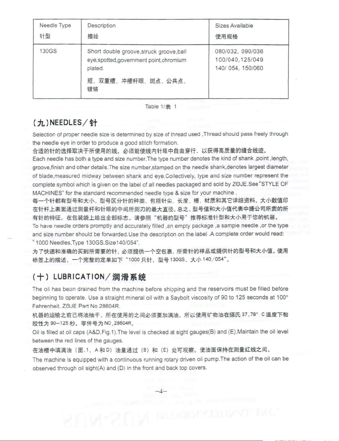
Needle Type
Description
Sizes Available
lt~
130GS
( iL)
NEEDLES
Selecti
on
of proper needle size is determined by size of thread used ,Thread should pass freely through
the needle eye
~~~lt~--~~~M'Ifm~~
Each needle has both a type and size number. The ty
groove,finish and other details. The si
of
blade,measu r
complete symbol whi
MACHINES" for the standard recommended needle type & size for your machine .
4it-1'fttrifl"~~~::k!J'
1£lttf
..t~iiD~~3'!
fllt~¥.HiE
To
have needle orders promptly and accurately filled ,
and size number should be forwarded.Use the description on the
" 1000 Needles,Type 130GS,Size140/054
.
1£'€!~~..t~lli~$~;t
~7•~~*~~~~PJT~~~lt
~~..ttt-.JJI~
.
m~
Short
double groove,struck groove,ba
eye,spotted,government point,chromium
plated. 140/ 054 , 150/
~-~mm
w~
/
tt
in
order to produce a good stitch formation.
ed
midway between shank and eye.Collectively, type and size number represent the
ch
is given on the label
.
1J
fitf~ltPR~~
-1-:lt~tt-.J:iE~~l'
.
;
IPiffHtL
.
~~•••~lt~~~~•fi
ze
number ,stamped on the needle shank,denotes largest diameter
~~1&5Httt-.J~~.
fBJPJTilj!
.
.
~~mm-t-2'€!•
"1000
itt~. 0~,~
1/
Table
of all
~
pe
needles packaged and sold by Z0JE.See "STYLE OF
'€!t!~t~.
~
3J
tt-.lft::k1if£
iW~!ffi
".
"
.fJl.Hif.J~-€5-
JUt
.
~~
tl
-
1
.
number denotes the ki
*li
.
fl
• .
~.z.. ~~1ft~::k,Haft~~i!0iSJPJT~~PJT
"
ffH~~~~H~~::k'J'm~1$tt-.ltll.H
an
empty package ,a sample needle ,or the type
label .A complete order would read:
.
m~H~~B•mmH~~~~*!J'mo•m
130GS,
:::bJ'
'!fffl~m
080/032, 090/036
100/040,125/049
~&~~-·~~~~•.
nd
of
.
Mmi~Jt'E:ltFm~~
140/ 054" .
060
shank ,point ,length,
.
::k!J,ti:ili~P
.
The o
il
has
bei3n
drained from the mach ine before sh
beginning to operate. Use a straight mineral oil with a Saybolt viscosity
Fahrenhei
.fllH~~t!trzlltr2*t
~1i;/;J
Oil is filled at o
between the red lines of the
1f5mf!~tJ~
The machine is equipped with a continuous running rotary driven o
observed through
t.
Z0JE
90-125
Part No.28604R.
5
1Mdl-=f
.
m1£•mtt-.~z
fJ;
o
*14~
il
caps (A&D,Fig.1
;
m
<
oo.
oil sight(A) and (D) in the front and back top covers.
1 •
~NO
ga
A~
o)
,
28604R.
).
The level1s checked
uges.
;m
f
BJ~,~!ii~no~;m
i!~
(B)
~
i;:>
ping and the reservoirs must be fill ed before
.
PJT~:J.1i.FJHit~;m1£NIE\:
at
sight gauges(B) and (E).Maintain the oil level
<E)
~
1iT~~JR
.
il5m®f*ffl1fiYltl•tl~z
il
pump. The action
-4-
of
90 to 125 seconds at 100°
37.
1a
· c
71!~1'~
fBJ
0
of
the oil can be
Page 10

THREADING & OILING FOR PLAIN FEED
·li~M~R9·~R.iJtjfb
I
or
2 drops
or
oil twice o week
-
Jil~1!!1~/X
' I
I
\
""--
2 3 1
---
//
CI J
A Oil Fill Cop & Oil Sight
B Oil Lovel Goge
C Pump Primer Screws
0 Oil Fill Cop & Oil Sight
E Oil
level
Goge
FArm
Oil Drain Plug
G Looper Position Knob
/
J
(
I
I
""--
__
;::/
~illil
l!!!~*.;:p:~
ifil~!Si;IJit~~ItU"J
~fiji]'
;J1111*.if1.~
1-l~l!!!~
~tt:lEttt!~
\
FI
G.1
MINIMUM OIL LEVEL
.
1"'
at
I
I
MAXIMUM OIL LEVEL - -
~-
- 5-
Page 11

TliREADING & OILING FOR DIFFERENTIAL FEED
-~~~fll.tf9J1tlR.~jJij
::x
2 drops
or
x
LNice
o
week
-JI~;}Ijjiij~
•
•
A
Oi
Fdl Cop & Oil Sight
B
Oi
Lovel Goge
C
?t.:mp
Primer Screws
:>
Oi
RIJ
Cop & Oil St
E
Oi
leve
l Goge
F Ami Oil Drain Plug
G Looper Positi
on
_j
,/
&
I '
(
I I
\ I
"'-.._
__
ght
Knob
s0,
)_
/
FIG.1
MINIMUM OIL LEVEL
.,J,;ma
MAXIMUM OIL LEVEL
il::*:illla
- 6-
Page 12

mti~R7
w-~.f£~~1§-mB
When starting a new machine. beginning filling the reservoirs
that has been
screws(C).Apply oil to these holes and operate machine
.Replace screws(C
~~mMmHdmH~I-~~~J§-~A~ffl~~~~~~.~~~~~~-~~-
S*~~~~~fl(C
(C).
CAUTION:
~~=
Oil may be drained from the machine
and plug screw(G )at the back
~~fi~J.A.tJI.Htt-l~?~imHfi
~1¥-JJ§-W.
••
@ft··~~~~-.~~~-~.~~@~~~~~~82(A)~(D)-~~~~~
!
U.!.il.~
.
·i
dle for some time • it may be necessary to prime the pump.
).
l . .f±R~-~#A@.mBI~~-S~~~~~~~~~
If
oil does not bubble when machine is running , the circulating pump is inoperative.
~•~mH~H~~-~~~M•~•In
at
two places ,plug screw(F)Iocated in the bottom
of
the main frame below the handwheel.
. -~~!.!~~fl
(
F)
-E-TIEf!I¥-JJiUU~
of
when beginning to operate a machine
To
do this ,remove the two plug
until bubbling can be observed at the windows
-
~7-~I~.~
.
~-~-~~~fl
.
-
~~~$1fl
(G)
-=¥~1¥-J~W
of
the cylinder
.
.t.tJI.
<+-)
A convenient means for threading the looper has been provided. When loopers are at the left end of their
travel,press the knob(H,Fig.
the machine as illustrated in (Fig
flt.]j{l~Jr5!.f£f1ilit
~~3~B1fi7. ~Ill
<+=
NOTE : Instructions stating direction
relative to operator's position at the machine .The handwheel rotates counterclockwise
direction ; when viewed from the right end of machin
~=~M3m~~ma~&~~~~m•.M~M.J§-.~.S#A~ili-em~mH~~H~M~tt-Jm•
~~-~MmHtt-J~J§-wt~
<+=>
Torque specifications gives in this catalog are measured In inch-pounds or Newton-meters.AII straps and
eccentrics must be tightened to 19-21 in .l bs.(2.1-2.3Nm)Unless otherwise noted.AII nuts ,bolts ,screws,
etc,without torque specifications must be secured
torque specifications for connecting rods,links,screws etc
illJ:~t!Mt~~*~~ilitt-l~m~~'i"
L:t-·*)
!J'!i!'Jii~~~~rr$
THREADING
/
~ti
1)
and loopers will back out
.1
).After threading ,push loopers back into position.
.t~~. ~
<11!.1)
f1iltt~'8~~1¥-J!l~itl
PJT?f-.
~31~~1§-. tef1ilttfl~I*Ui
) ADJUSTING INSTRUCTI
of
location ,such a sright, left, front
.
-=¥~~¥-J~ff~~~~~n••
TORQUE
t:R~tl~.
REQUIREMENTS
·
~~.!:f::
~~1:1fa'8i)t.P.ij
.
~~~:•a-ei5lP.ij
.
~H!PJT1ftt-lil¢~.
.
~~m~m*~ti*T.
of
position,leaving them easily accessible . Thread
.
ti~OO~tit-'¥
ONS
/
~~i$tM
e.
·
/
tfl~~*
as
tightly as possible,unless otherwise noted.Special
..
are shown on the parts illustration
·*·
JiJT1f&:$~~1ia~L.'n~~m
t~tt
.
t~fl~if?.~,~~~
!1'.
(H.
Ill.
1 ) •
.
or
rear
19-21
S~n~.
~~"i*tt-llllir-.
f1iltt~lc:JJ§-8tfH~
of
machine .are given
~'i"·~
.
~-5i·~~iR~::k
,i
n operating
s.
(2.
1-3.2
C+
1m)
SYNCHRON
IZING
NEEDLE
AND
LOOPER
tt~~tta9fcl'!Vm~
- 7-
MOTIONS
Page 13

NOTE: Needle and looper mechanisms are carefully synchronized with precision gauges before leaving
the factory to insure the best possible sewing conditions.
~=~7~~~~~~~••.m~~~r~Mm••~~~*••~~~~~.~ff~~ff~M~~~
~
.
Should it become necessary to disassemble the main shaft or
replace components of the needle or looper drive mechanisms,
FIG.2 (00
FIG.3 (III 3)
2)
re-synchronization
proper sewing adjustments. This is accomplished by means
an adjustable split coupling located beneath the rear top cover,
connecting
the looper mechanism.
~*~~m7f
the
~ff~rqff~~~tt
-~~~m~~mm~w~~~~-H.
m.
t::~rqnm~~~~~~•
To
synchronize the machine,remove the needles,presser foot ,
throat plate, feed dogs and upper feed roller mechanism.Rotate
handwheel in the operating direction
the bottom of its stroke and just begins its upward travel .Loosen
screw(A,Fig.2) and remove the looper for the
from the looper holder.lnsert a strai
9mm) or 11/64"(4.3mm) diameter by 2-1/2"(63.5mm) long into
looper holder
the rod (B) is at the extreme left and reinstall the throat plate.
Loosen screw(F)in looper holder and move the ho l
right
until the nght side of the rod is approximately 5/32"(4.0mm)
from the left edge
handwheel in
rod(B)comes
point,clamp
(D),flush against the underside of the machine casting(E).Rotate
handwheel in the opposite direction
contacts
clearance between gauge and casting
is .005"(
~7~ff~rqfi~~~M.~*ff
~"l!t~fJ1~.1Sm~l"1floJ$tM~~1U1Jffff~'2~~~T$Jtii~ii
i1Bt7:J.l1:
).Arq~tfi~~lfl.
~. *1l7:J63.5mmitt.A.rqit~tt:.§.m:~tt1\Hitr
~li~Jff
(F)
the edge
0.1
mm).
. t/l7Hitr (
(B)
jf:
.§.te!~
of
the machine will be required to facilitate
of
crankshaft to the main shaft, which in turn drives
::EffE!£~H§.trqH~~Mmf~~~IWt.
.
~-~~~~~~-~-~--.~~
~~Mm~::tffm•
.
until the needle
ght
steel rod (
and
retighten screw(A).Rotate the handwheel until
of
the throat plate,tighten screw(F).Tum the
the operating direction ,with needle
in
contact with the edge
lin
ing gauge No.TI147(C)around the needle
of
the
throat plate.Maximum
A,
lfl2)
fj)...][WJ~
of
the throat plate.At this
until needle
or
rod and throat plate
.
ff~.n•.mM~~~m
1f:.§.3Mrqff,
(B)
][@~
3.
.fffi1.iit!tf:.§.ff~lt•~.l1:.
loJti§.tloJ{i~Mli~Jff~;(:lit!~it•~
~~~Q
bar
is at
left hand needle
8)5
/32"(
3.
der
left or
bar
rising until
bar
bar
or
the rod
allowable
fflti~1Erqff
9mm
§!
4.3mm
(A).
:k
~M~
f'/l*rq~t~~tltJ
ti
it!:k~f.J
- 8-
Page 14

4.0mm
TI147
mm~~ttfr~ttf&tr.:litltiH»;.t.J.ll:
~~fJJ.ft~~~~~~~~~im~~~~:
and set screws.
the coupling . The holes in the main shaft end of the coupling are larger than the diameter
permitting severa l degrees
snug the uppermost horizontal clamp screw enough to hold coupling (A.Fig.3)in position, If the handwheel
is turned in reverse
casting(E)before rod(B)contacts the edge
which was snug ,while holding the coupling
synchronization. If the handwheel is turned in reverse of operating direction and the rod contacts the
edge
turn the handwheel slightly in the operating direction.Use
clamp screws(B.Fig.3)securely,and recheck both clearance points with .005"0.1 mm)shim gauge
,
rt~!lfl
(C)
~.ftttfr
If
machine is not synchronized the following applies :
Both ends of the adjustable split coupling are secured to the crankshaft and main shaft by spot screws
Loosen the three horizontal
handwheel slightly
of
the throat plate before the clamp gauge contacts the machine casting ,adjust as before ,except
1 mm)exists between gauge and casting or between rod and throat plate ,in both the operating
reverse directi
no slippage occurred
~~~1lHtr.:J~~$m~un~~~un~~~m~±fr~1l$~
~~~=
~~itFaJ~
lf~:~Ulfl~$il~1lH
ll!.
Ul:ft!MmJt~t&fltrt~~~t'fl
FaJ~tt
mtr.J
it-t&~fBJtr.:lfBJI!Jit~Sl:.t
1mm
4'tlfl (B)
•
2)
~fJL~
.
~~~~$~ft~.&:JJicl$tiM
-~.
•·-~~~•••tr.J~icl~•
tr.:J~R~iJiH.iE1£rt~tlflm5.2:1i~~~~
(F
),
i
S~ffJ)jo)fdi~~~]i~Jfr
(D)
J!lmJ!H1J.~/iiim
.
On
the main shaft end
of
rotation in either directi
clamp screws(B,Fig.3).With rod (B.Fig.2)at its farthest position to the left ,
of
operating direction and gauge(C.Fig.2)on needle bar (D)contacts the mach ine
in
reverse
ons
of
.ftLHf7]<1JL~A.l:tr.:J.::.
of
operating direction,snug the uppermost horizontal clamp screw(B),recheck
the handwheel. When th s setting has been made ,tighten the three horizontal
whi
le
tightening the screws.
tr.:ltfllL'f:ilkl~L
o
-1'~-~fl
(A, ll!.3)
(E)
~1llUtff
0.
1mm
(B)
~tt-t&li!tlti~~
(C
).
.
~~~~$.
(E)
~ll:ft~f/l;te~fr~tt-t&tr.:Jit:kfti~
of
the coupling(A,Fig.3)three screws(B) thread horizontally through
of
in
±+f~tl~.l:tr.:l:tUt:tlflli~:k
(B.
:iE:Ul:
.
~~-=f~iS~~-T~.&:JJicl$t1H3.itff
~~$£~tr.J.&iaJ~$t
.
ff~it*itl~1l~~n+r~•a~m~tr.:J1l~~
.
~~~~.&••a-t
(B)
tliif!Jttf&tr.:litl!'l;.t.J.ll:. Jit!M
.if~T
•
.&:JJio:Jtdi~~~]lf!
on
to properly synchronize the needle and looper.
the throat plate loosen horizontal clamp screw(B.Fig.3)
place with
!113
). il+f (B,
t9~7]<~~Atlfl
.
an
Allen wrench
sh
im stock to insure no more than .005"(0.
.
~±fr~1lH<A.
.
llJ2
)
Ul:-Tii~li!
•
.ft£1f~~tr.:l*lf~Atlfl
.
rt~*lf~Aitl:imtr.:J~fl
.
m~R~s~~•H~m~~~~+r~
(B.
00.
.
:iEIM~
J
iU~NO.
Jl§
.ft1lttfJJ.~tr.:l.l:$~ti"fr
f
BJMi~
o.
1 mm.
of
the screws,
in
set screw(C).Rotate the
and
to
assure
~3>~$.l:tr.:J
fti!fB:-:JJiclifJJi:tr.:ltdt~il~~t
.
il~itr-Tii:f-5~tr.:l*
(D)
1:~~-H
(B,
Ill
3),
¥H~itll~~~
(B).
.
~~~..tw~
3).
#.§.~4'.~tr.:li8JI!Jli.
(C,
~IJT~i!f
m
0.
C+
.li.)TIGHTENING
When replacement of the needle bar, and
bar 14-16 in
the purpose
torque rod in the hole at the upper end
suitable
bend,the needle bar head has been threaded into the needle bar properly.
~~Jt;~itfr~it~IM
N0.21227ARtll~ff'2!!~fJJ.H!MiifHiHi~tr.:J
.lbs.(1.6-1
of
too
l,
turn the needle bar wi
.8Nm)
eliminating the possibility
,
NEEDLE
or
use torque rod No.21227AR that has been supplied
th
bUt~f!J~tfftr.:Jtll~;.t.J
HEAD/rtatt§k
or
needle head is necessary,torque the needle head to needle
of
distorting the needle bar due to overtightening. Insert the
of
the needle bar, while holding the need le bar head with a
the torque rod onto the needle bar head. When the rod starts to
1
4-16
.
,Eft-T
~"t · ~
i
ili~~-Ti:l:~ii'iiilitff~!Hitr.:li~m
- 9-
(
1.6-1
with the machine ,for
.8
t:f
· *)
~~ilm~~;.t.J
.
~J§~m~IA
Page 15

Rtt~~~"~~~~•~w~n~mAmft~.mm•~••~~.~~*••~"·~~~•&•A
ttff
.
C+*)ALIGNING
tt~tt'-&.1:~1\..&l-B:t&
FIG.4
FIG.5
(00
(00
NEEDLES
4)
8
5)
IN
THROAT
Insert a new set
(B,Fig,4) slightly loosened,low
head as recuired until the needles are centered
plate needle hole slots . Tighten screw (B)torque to 19-21 in.
lbs.(2.1-2.4Nm).
1liU-...1Mt.
ff
(A)
jij
19-21
NOTE :
slots , the lower cylinder must be moved as stated below.
5:%:
~~at=1'~ttt&~~nfiX-1i:t£
2.~~~to*'J'
#S~~£31('~-tt~l[fijftift-Tltf&fL~tpJl,'jJJ.t.
~-t · ~
If
the needles can
PLATE
of
needles , type and size specified, with screw
(
2.1-2.4*
SLOTS
er
needle bar(A) and tum needle
in
.
~~f't}3H
not
be aligned
..
UJ
(B.IIJ.4),
· *>
~m~rt~UUJ
in
the throat plate
.
l'f11.~-;E1'£1'Wt&3i'JJ
the throat
~ifflt
(B).
7 .
C+-t)CENTERING
THE
CYLINDER
lE*'l.~~lt\
Remove the top front cover and gasket from the main frame.
Loosen cylinder holding screw(A,Fig.5).Turn eccentric screw
(B)clockwise
needles are centered in the needle holes.Tighten screws(A)
torque to 18 ft.lbs.and recheck settings.
~~m~
(A
.IJ].
~ttift-Tttt&n~rp~r.'
#
.§.JiiJT~~~gc
NOTE:The cylinder may not move freely when the eccentr
turned because the joint sealant compound has set.
ii::
~~~L.'$t~f;IJ"
a-tl'fJI.~~i!~!lt~~
or
counterclockwise to move the cylinder
<m~>
5)
.
~~m~~~m~*~
l®i"H~i$"ttJtffft'UiaJL'~n
.
mm~:tJ
.
.
~fJI.~iiJ!i~=1'~~~~3f;IJ
7!J.l!Hf'J
·~
*m~~~~~n
(B)
it.l:f11.~3f;IJ1!
1a~-t · ~~tt~t~n
<
is required, loosen screw (A,Fig.7) in looper holder,permitting
movement
dimension as shown in Fig .6.Retighten screw(A.Fig.7).Repeat
for other needles and loopers.
fi.APJf~~~~*'NfJilrtt
~~~tt. 3~ttW:Tjl1.£:illa:t.
tfJJ"Dt.am!ie3.
(C)
~~$j;'{!tf.Ji}IJ~
FIG.? (
Rotate handwheel
to touch but not deflect. This adjustment can be made by loosening screw{A.Fig. ?)in looper holder.
holder can be moved front to back to attain looper to needle setting.Aiways check the 9/64"(3.6mm)
looper gauge setting after setting the looper to the back
setting
of
the looper to the back
~~ft:n~•••~~~•~ttm~~~w~~tt-.Jttmm~m~•~~-
(A,
IE.
7)
tf.lt!}~*if.Jfl
tf.Jmi~~.
tt:E£sW:ll.iE~
The amount
the amount
contact the back
~tttr.l@l~lt
w 1 / 3
m
3.6mm~ttif.Jtift*~~
of
of
avoid it is recomended as a starting point ,to have the points
t:ar~i9:7-J
~
tfJ
~~~
7>1
00
7)
in
operating direction to assure that the looper point passes to the rear
of
.
~tt~~$1ltr~~M*R~~tt£~Jtttf.J~~iJU~
o
looper avo
of
~~
id
has been set at the factory to .110"(2.8mm).lf it becomes necessary to adjust
the lower 1/3 of the back
2.
Bmm
.
jzDW:~Jt;iJU~
,•:'Bltiltrrif.J
fl.
(A,
00.
ff.o
IHIT?9~~fl
the needle after setting the 9/64"(3.6mm)looper gauge.
o
#..Eim.&it?.
of
in
either
Smmo
fi}'ij~~j;J
7
).
ff -:1J
.
the looper blade.
@ill:.
icJtf.J~M~H*R~~fie~3.6mm,
(A.
of
the needle,and conversely,always check the
.{£~~~3.6mm~ttif.J~~~~~~.{£tt~tf.J~
t~t:r.¥m
B:tt~~~tt'Wimmtltttr.lffi:T~tt
direction
o
jzDW:if.Jfi~Jt;.
to
attain
I
-~stif.lfltiilltf.J~tt
fitt
NO.
21225-9164tfJ~ttif.Jflft
the 9/64"(
(B)
tf.Jtfl'L'~~tt
f'L}7f~tt~J:tfJ~fl
3.6mm)
(A.
fll,
6)
(
A)
jmi¥J.6Plf
007)
o
Jt~tf.J~tt~~tl11=£-.f$tf.l
of
the needle
o
~~~~~tt~tt~...ttt-.J~n
o .~d~:ttii.W~~tt~tt§im
of
the decending needles
o
looper
D'Jl'
<+it.)
:il.
NOTE:Whenever looper avoid is changed looper clearance to needle must also be reset.
~:
<=+)SETTING
The height
of
the looper, with the looper point even with the right side
SETTING
Coronec:t~.n;
Roc:t
O.f'erenta.
l!fifrt$JJ~~
3~tt@l~-~~§. ~tt~tttr.J~~~~-ENft
For
Feed
.· _ _
~~
FIG.8 (
of
the needle bar is correct when the top of
THE
'-'A
•
..
• j
-
00
8)
LOOPER(CONT) /
If
more or less looper avoid motion is required.remove cylinder
side cover(A,fig.8)1ocated
screwdriver to loosen looper avoid link ball joint(B).Moving ball
joint down
motlon ,moving it up acts the reverse.Retighten ball joint(B)
!
i
:~
·-·
securely.
~tt~u~~~~~~£~Jt;tt-.J.~""Fm~~imt£l'~tr.Jill~
(A . Ill.
~tt@l~J.i'~~ttl'~~@]~-~~.
~-~tf(2)
in
the lever slot increases the amount of looper avoid
B)
o
~iJ~JJtL}7f~tt@limf.1'~;fHI~tf.JJJ~~
(B).
o
HELGHT
OF
NEEDLE
the
BAR/\i.tttf-aJI
needle eye is 1/16"(1.6mm)below the underside
of
the needle
at
the lower front left side.Use a
jzDW:tt...t~~-~~~
.To
make adjustment loosen
-11-
(B)
.
fe!
Page 17

TORQUE.
19-21
1n
l
bs
(2 1
-2.4Nn
)
W\
8
A
screw(A.Fig.9)and move needle bar (B)as required to attain
dimension.
s
H~tU91fftri1il~t~
it.!ili'ili.~
M~ff
NOTE: Care must be taken not to disturb the alignment
needles when moving the needle bar either up or down.
;1,
.iE
ila9. s~~if.l~M.
(B)
f!Jiilf~;j((f){ftii
,J,/L.,a93M~
1 .
Smm
a-t.
l!P~i1il~~1£~a9~ltl.
t'LHUJ.tr
.
~
~t1\~a9B:~11sitff
1:
CA.
!E.S)
1'3MM
~ff
#iH~
of
the
.
FIG.9 (
(=+-)SETTING
00
9)
THE
FEED
DOGS
FOR
PLAIN
FEED
-ii~M*JL~M>fa9~-
Assemble the main feed dog and throat plate.Main feed dog
(A.Fig.11 )at its highest position,should be set to project above
of
the throat plate,the depth
screw(B)and front support screw(C)should be set
this setting.
~~±l!*-1~ft1~t&
a-r.
m~ue~*4*~Htt&~j;f~-~~
(B)
~fiiW(fJ~JJ~tJ
The feed should be set
the front
throat plate when the feed dog is at its most forward travel, The
same amount of clearance should be between the back
feed dog and
the feed dog is at its most rearward
loosen screws
a
counterclockwise to obtain proper setting. Tighten screws (A and
B),reinstall plug screw(D).
s~~*1£~~~~~mwa-r
FIG.11
a9iiEY~Tl!~~~W~~tt&~f+:rt.~~W~f8Jlle:k'J'
-T~tr
B)
(
D)
*!H~llti~JI
,
~1\f~-T~tJ
(D).
.
fflU~JJJ®ia1HP11$M~~~~~L.'ft
t&~~:rt.fiiW~f8Jlleii
screw
of
the feed dog and the front
driver
.
.
±i!*-1* (
the
back
(A
and B,Fig.10)and remove plug screw(O).Using
turn
ili::tf'L}ff
its teeth.The feed dog mounting
A.
00.11 )
.
(C)
~~it-t,
so
there is equal clearance between
of
the feed slot in the throat plate when
eccentr
.
i!~•m~Ti!~~~mw~~
.
si!f+~1£~~tlla9-!l~itia1,
gc
~i.ltr
(C)
~jJ~f!Ji~ti§la<J
EY~$~~-1-i~~
of
the feed slot in the
travel.
To
ic
pin
(C)
(
A~B.
to
maintain
{ftf~'T~a9l1t~~
l!~*a<:Hiflt'n
.
of
the
atta
in
this setting
clockwise
or
l!MA
l!l.10
)
#.§.3M~
.
f?~~tr
(A~
( = + =>SETTING
THE
FEED
DOGS
FOR
DIFFERENTIAL
~rJJ~Mm~M>fa9~-
Before assembling the main and differential feed dogs,set the feed bar eccentric pin (A,Fig.1 OA)Iocated
in the left side near center
of
cylinder,so that the slot in the head is
in
a horizontal position. This assures
-12-
FEED
Page 18

A
D•fferentral
FIG.10A
FIG.11A (l!fl lL.\)
(i!B
Feed
lOA
a neutra position
main and differential feed bars simultaneously.The feed
pin is retained in position by set screw(B).Assemble differential
feed dog (A,Fig.11 A),main feed dog(B) and throat
the main and differential feed dogs can be individually adjusted
to height.Main feed dog (B)at its highest position,should be set
project
to
adjustment is necessary loosen screw(D)and move feed dog
(B) up
)
should sLpport front
1£~f[]~JHJJ~*4~tr.J
1M)Q~~~~~J:m~~~~~~.~~M~~~M~~*
.ifLffi:.W
tF.lLffi:ii,
00.
ll
>ftr.J~
~.
3!0*i1U~~~.
&•rr~~~-~-.~M~tr.J~·~(C)$
mw
above
or
down to attain correct setting.Feed dog support(C)
.
~£7J
~t~tr
A)
i:~*4!}f
• •
i:i!M>f<B)~~fi-ffi:W".m~~--
.
of
eccentricity for the purpose tilting
the
throat
of
feed dog .
~
~iitr.
7~fll~HdJ~*4~!BJatf1§f~at,
(B)
ii~*4**tt~ift.
(B)
fCH-t&
tk7f~lr
plate,the
5tiJ:~*4*'J:~1fiijll,'§;t
.
~~ljif.Jfl~i!~~f[]
(D)
depth
#.ElJ:1'3fJJ~*4~
of
-f*iiE1fiij1L.'~~~
~~~fJJ~~>f
~
-1£~M~~
of
the
bar
plate ,Both
its
teeth.lf
(A,
00.
(A.
~fJJi! *4
-~>f
(B) ~
(=+=)SETTING
~i9J~Mm~~>Ftrn~
If adjustment is necessary loosen screw(E,Fig, 11A)in feed dog support(C) and move as required.Retighten
screw(E).The differential
loosen screw(F)and move feed dog up or down as required.Retighten screw(F).
j(Q*if.l~~~.
M~M~
ffl~M~M~. •fJfrt~t~tT
NOTE:Should the main feed dog require repositioni
rearward travel ,loosen set screw(C,Fig.10A)in main feed bar driving link(D),rotate main feed bar eccentric
driving stud(E)as required, Driving stud(E)has a thin hexagon head with cutouts on two
movement by tapping with a sharp pointed tool,when wrench21388AZ is not available.Whenever the
main feed
adjustment may be required.Retighten set screw(C). Position main feed dog support(C,Fig.11A)flush
against bottom of main feed dog (B ),tighten support screw(E)secLrely.
ii:
3lO*i:~M~1£icllitr~icJFo3Mat~~t&mtl"
J:~~~~fl
~~ti.Ai£M"~¥[§J..t,
~H$~~t,SI&fd.l*i~m'fi~~~~.
~M~tf:J~~~
faff~M~~f$~
(A)
RTtiE.ttt"~~i!M>f
bar
eccentric dnving stud position has been changed ,recheck
(C.
00
.lOA)
(
C.
00.
THE
fP.Pd
dog (A)may then be leveled with main feed dog (B
~~~;~(;ijjf~~~M-1fiijll,'~grJJtltt
s~
l1A)
FEED
(C)
(B)
(F).
21388AZt&ttt~1i~ii:!t~Mat.
liNJT~i!tittf:J-f,'iH?~I~:Jt~:ef~~iJUl
~~i!*'f~
DOGS
J:tr.J!2..~fl
1£!BJ
- :ifiiJ:.
FOR
~
c2>
(
E.~.l1A)
ng
due to contact with the throat plate in its forward
.
!i!lJ
DIFF
#.El~Jffi~*~TJJ.
3!0*if.l~~~.
~i!M~~I!iJT~t&
(E).
~~~IH&~tr.JI~~m~:Jt~M.
(B)
tr.J~im1f-¥.
f?$~~stlll
ERENTIAL
).
If
adjustment is necessary
!ti/Tf?~i_lfl
t41f~fl
rear
~jgfj)t~~
.
(E).
(F)
needle guard setting,
.
t41fi:i!~HHgM~
(
E)
1i:ifir?~~~Uifl
FEED ( CONT)
#.El~~~*n
of
the flats allowing
:fir-~iiit~IT/,~
(E).~
or
(D)
~l!f;£~
(C).
:£
-13-
Page 19

(=+1m)
NOTE: If plug screw(A) is replaced with a
Any stitch length change,requires resetting the needle guard.
it
:
jU]=*~~...t#TI¥J:*:~-T~JlJ
ffffl~~"*~l¥1~~m~*~m~~~~~~~I
CAUTION:When making stitch length adjustment
due to possible part damage.
CHANGING
FIG.12 (
00
1
2)
STITCH
When cha'lge in stitch length is required,remove farge plug
screw(A,Fig.12).Loosen feed rocker driving link screw(B)in fever
(C).
l
(A
).
9}1J~ll$lf~...tiia!ijH!iii1it
LENGTH
Moving
engthens
Retighten link screw(B)securely and replace plug screw(A).
s~*~~tit~"*oca-t
r.ifim
/
it~ti~*Jl
the feed rocker driving fink up in the lever slot
the stitch ,
(C)
...ti¥J1iU~~Jt~gfif.J~t~lJ
~.lt~fif.l~mn~~•fif.l~~~"*~•"*·&z~•.••~*
~...t!¥JSllJ
new
plug screw ,it shou ld be sealed with a silicone seal.
(B)
#iH~...t:*:a-TillJ
.
do not
exceed maximum recommended stitch length
mov
ing
it
down ,
.
37f*•.:rt~n
.
shortens
cA.II!.12)
(B).
(A
).
the stitch ,
.
f'J}fftt
if.lfimM'P~l!~
v1S':
*~••~Fc•fif.l•~~•
-ifl~mi¥Joof}}M~~~tl:ltiM
CAUTION:If stitch length is changed,needle guard must be reset.
w•:jz0•~~*•~~7.
NOTE:When insta
loosen screw(N,Fig.15)in needle head and rotate needle to attain adjustment(D,Fig.13).
it:
}t~l]Plf~;j(ag~I¥J
3~~*1i~fjgifolflilJfti!fi¥JB::*:tit~*Lta-t
C=+.li)SETTING
D
FIG.13 (
$:RI¥Jtta-¥~1'rl!*4P~PJr1£1¥J1l~
00
lli
ng
.
(0 , 11}.13).
READ
13
)
.
a~i'iJtm~tr..J$:R~•
Hl¥l•ifl••~~~~~~
the needle 1t should be parallel with the eye
NEEDLE
Set the rear r.eedle guard(A.Fig.13)horizontally
contacts needles(B)when
adjustment is necessary loosen screw(E)and move guard front
B to back as required. It should be set vertica
yet have its guarding surface in contact with the needles until
the points
the right side of the needles.
screw(F)and move guard and holder up or down as required.
$:~~!r.JFcWJ.I<.if~I
~~ltJlJf~ft~~MilJ~
.
jz[]=*~~~~f'J}ff~li
.
jz[]·~£il!lr.t
.
911Ji'iJtm£EBr*f~~*
7 .
GUARD/ii·tf~Ji§'-tp5t.
at
its extreme forward position.
ll
y as low as possible,
of
the loopers(C),moving to the right,are even with
If adjustment is necessary loosen
(
A.~.
13)
3'81£iliiliii!r.JW:Iilt-t
(B) 0
jz[]=*~~Jnijf'J}fftlll'
.
m•3~~~cc>~~•fif.la-t.~•i£~1¥l~~.
(F)
#..El~.!ffi~31<...tl'8fif.J·:f?~-~'8!r.J~
.
in
li
n~
of
feed.lf adjustment is necessary,
.
f'J}fftt~...ti¥JiJ.lJ
(N. !11.15)
so
that it barely
lf
I
fl
(E) I
~!m£
.
#..El!tE~tt~
-14-
Page 20

(=+*>PRESSER
FOOT AND
PRESSER
ffi-~ffii1Jtftro~•
or
8
FIG.14 (
FIG.15 (
Set upper stop collar(K)to contact casting,so the bottom
foot do not touch,at the bottom
00
00
14)
15)
of
the needle stroke when lifting foot. Tighten screw(C) .
Adjusting
Remove presser bar
screw(A,Fig.15)on presser bar guide(B ).Loosen screws(C)in
upper collar and screws(D) in needle lever thread pull-off lever
Slide Presser bar upward high enough
yoke(E)with foot attached and tighten screw(F)
bar.Positi
with the holes in the throat plate. Tighten screw (A).
if.l!ht~~ffi~:
31fffi~jt~
~~n
~IJ;fF
J:~tlfl
( E )
.{£
t~fi.ffiM.Il.l.~ttn!3tH&J:~n.o.t
Presser foot guide plates(G,.Fig.15)should be set so that entire
presser
with no
ffllt.llsl~±~
~~.fflt.l.~~~..t~3IJJ~~~~~3IJJ
With foot proper
guide(B,Fig.15)securely fastened to presser bar,adjust both
guide plates(G)to obtain above setting. Tighten four screws(H).
l!lBG-ffiB!Il.!:ittt&~~~.o.t-Jiti
.ffittrie~$00,
rr~~mt-ttn
Reinsta
foot resti
l!:ii#
ffllt4ltt.ff~H.&..t
Replacing Presser Foot:
on
foot so that the needle hol
C
A.
!i1
lt
.l.
EHtHJt
foot
and bar assembly has free movement up and down
left to right movement .
<G.~.
ll
presser bar spring(B,Fig.14)and knob(A),with presser
ng
on
BAR
(B,
. 15).
(D)
.
ffi.ft14J~J:iif~
iJJ
I fT $
1s>
ly ali
if.Jfl~i's[~i}C
<H
>.
throat plate.
I
of
the needle head and the top
ADJUSTMENT
leaf
spring(B,Fig.14)and
to
es
lf!.14
)
~~~Q;
tLHfJ:W~fi14=..t~i.ln
.ffi
;fF
~~~~;t)
gned on throat plate and presser
ffi~.ffi;fF5!j1jf(B.
(B),
ftHfSI~.ffi;fF
.fE.$~iffi
iii
...1:
-
.
'l!.ffi!*.lls
(G)
J.iil:ffi.ft14JJ:~.ffiJ!141~
~tifT
1H&. rr~~n
7fi~t-
~~fi.t..titi8i!:St~~~
~.
nut
(B).Loosen
..
slip on presser foot
on flat
of
presser
in the foot line up
(B)
..t
c
c>
~13tr&m
(F) 0
00
~.ffi!!ll
ffiM.Il!3ffM.IlfF~~
.
l
~~
(8 . 11!.15) !3
14
)f[liJ~tL-¥
of
the presser
c A
>.
(A)
~
UL
bar
.
0
~-..t~IJJ~CK>~mti~~
m~.
rr:~un
The presser foot should be adjusted to be 1/8"(3.17mm)above the throat plate before the feed roller
mechanism begins to rise
guide as required to attain the specified point at whi
and maintain needle settings .
.ff~~~m~1f9ii...1:7tiWffiB!IIE~R~~tttt&~
15).
~!ffi~;}(7t~~~flisl~~ii~fti1JJ!*4i9-~F9ii...l:7t~11~1'Ul:il
cc>.
.
~ffillt.IJ&&H
..
Loosen screw(A,Fig, 15)
.
3.17mm.
fifi~BS!3X~~.~tt~~--~.ffillt4J~M$~~
in
presser bar lifter and guide (B),raise
ch
the feed roller begins to rise .Retighten screw(A)
fl}1f.ffifFti7tftl51~14=
-15-
.
rr:itlfl
or
CB
>
...l:~~n
(A)
#..El~R$tt
lower
CA. 00.
.
Page 21

NOTE : There should be a minimum 1/32"(0.8mm) clearance between screw (M,Fig.15)and the bottom
of
the slot in link(J).
Regulate the pressure on the presser foot by turning the presser spring regulating knob(A,Fig.14) located
of
on top
To
Needle lever thread pu
foot is resting on throat plate.
it:
i!l1:ME~.ffiffSfffNi..ttr..l~IIP!
3fJJIXJIJ;ttr..J.ffi~~~~lT
3
IfMIJ~.ffitt&J:If.t
(=
~~~~tY$tf!Jfe~..ttr..Jif7W~l':
te~TJJ~n
Jm.AJW~~fJJtYte
~ZfBJ~J\i!fft&te
i±~itl
~.-
#..Eltr~Ufl
pressure foot spring (
remove just the presser foot, remove screws (l ,Fig.15) and replace foot, retighten screws (l ).
ll
-off(P) should be set 1/16(1.6mm)above bottom
illY (
M.III
.15)
Ej)!1f~tr..!JlHL
(
.
~~~.lH~ltiJ~
+-i:)UPPER
<
.
fittfl
<E> m~
FIG.16 (
A.
.
(H).
00
oo
1s
)
~~1£i!fft&~~
(E)
**~i*tit
(F)
(G)
<1!*4t&$U~!IaiE~71.iioJJ:£19)
~~t!T$ttr.Jt£ii1!:ff~~wtr.Jt£ii1m~
B).
(J
)
tr..!llitNBJil*@;fJO.Smm
(
A.IIl.
14 )
~~ffiM4!~1Jo~3
L.!fl
.15)
jt:.§.J!t~.ffiM.P.
( P)
Ji!Z
tt~ 0 Jfiiiitr..JR.~
FEED
16)
ROLLER
Assembly of Roller to Roller Yoke :
Assemble
Place woodruff key(
dr
ive gear (E)on to shaft {D),make sure key(C)goes into slot in
gear
between
assembled components through frame. Make sure that shoulder
of roll
direction on
shoulder of shaft( D) against face of gear(E),make sure
of
is against right (inside) face
of
roller is against face of
shaft (D) and tighten screw(H).
<B> ..t.
(C)
iltA~~fJJtS"fe
1fi
.
te!~~tS"~ff
of
slot in cover (Q)when presser
.
tr..J.ffiJJ
.
IiJfrt~tlfl
ADJUSTMENT/
dr
iven
gear
(E).While holding feed roller frame (B)with steel roller(F)
tt"le
two
er
(F)is to the ri
roller )on the flat
tef.mlff~m
(E)
1¥-Jtittl*
(D)
~~~~~Hq:tll\li*
~ff
(
E)
<
1£~w~~i21m~
{L).
1 .
6mm
.
..t~MtS~tJ9~-
(A, Fig.16)through feed roller frame {B).
C) into slot
frame l
obs
ght
gear
cc>
fi5lf!Jj!f:tteff
·
a93Fimfit-~F
of
feed roller shaft (O).Siide
, sli
de
feed roller shaft(O) and
.Align screw (G) (first in
of
shaft (E).At the same time thrust
(E),make sure left edge
of
left lob .Secure screw(G) on flat
<D>
tr..Jt~M*
1£~~~-tatel¥1~
·
~~lf.ti!.Fkt!i~I¥-J~i:i'
.
IEJif.trt~ff
>.
¥r$ff
<D>
operat
(
B)
..ti¥-J"M
(D)
tr.J~i:i'Ej
..t
a9t~n
ing
left edge
of
roller
·
ff <D>
-t~
(F)
1b.
<G>
(=+)\.)UPPER
..t~MtS~tR:R•c
When feed roller mechanism (C,Fig.17) has been removed or replaced,.003
(0.13mm) maximum clearance should be maintained between roller and throat plate.
3i!fft!T$tfil.~
(
C.I!I
FEED
. 7)
3fJJ79!J!~
ROLLER
71f-t
ADJUSTMENT ( CONT)
2 >
.
Ji!Z~f.¥w~~tt.t&ff:JifV
13mm.
-
16-
ft(
0.08mm) minimum to
N
BJ~;f)o.osmm~•*
.oos
f
8J~=*.J
a
o.
Page 22

To
Adjust Guiding System for Roller:
Loosen
Mechanism(C)so that the roller is .003"(0.08mm)to .005"(0.
13mm) above throat plate.S iide rear guide finger(B)down so
that it sits
sure roller is
H
A
E
c
FIG.17 (III 17)
iftl
fl)!
~
t.9
$t
k
1¥-1
.ffi
1J
:
~i!~t.9~kbi1.Jo-~I¥-Jffi1Jif~'2fl.lE~I¥-Jff1Jf'Fffl~1llkiJ:J!~IYi~
$.1®ill1ttldf~JiliJ:i!~~ki¥-Jffi1J~1.Jo
Setting
Guide finger for roller should be set so that entire roller mechanism has free movement
no left to right movement .With roller properly aligned,the edge
in
Gui
guide plates (F}agai
place.
ifo]f!J!~i&~:
~fl-&~tr.Jsl~mmzifo1fltr.Ji.tm1-i!t+-&~mf~~~Etltr.Jkl'~~ii'il~~.tr:~~~
111.
a .
of
Feed Roller :
throat plate.
de
plates(F) must be thrusted against gu ide finger(B) to secure feed roller mechanism(C).Thrust
nst
guide finger(B) with eq ual oressure .Tighten fou r screws(E) to hold plates in
~1¥-Jiti~EY.lJ!.~l"-=fttf&~ftfl
mffisl~±.k
<F)
1!aX1sl~:fl1i
(A) to secure feed roller mechanism in place.
~iftl!lt.9~1¥-J51
t~1fWitltr
ttt.&~0
~~-~ (D)
~~Wi~tr(A)-fii!~w~m~oo~~~lir~k
Setting Pressure for Feed Roller:
Regulate the pressure on the feed roller so that it exerts
enough pressure on the fabric to feed the
Turning roller presser regulator (H,Fig, 17)
or
.
&Z.~~
.
si~±.k
<B)
Wi1-:tiioJ.ttr.Jf'Fffl1Jt€!~
two
screw
(A}
.Using shim(s)
on
top
of
rear guide support block(
parallel to throat plate slots. Tighten two screws
~~~1E:
(
A).
J'IH~R~Jl:J!~t9-~t1lt~
.
08mmi!J0.13mm
1¥-JNi~A.LL
counterclockwise to decrease the pressure.
.
(F)
!JC:,~1liioJiitrJ9Hisl~t§
o
ioJl'ii~Fcsl~tti
~i'fli11i*~~ltB~3JZ~l"T-ttf§AI
.
~.ffi~~-~$JJ~
of
roller should be parallel with feed slots
(B)
il:i!ft"W*tfft~
.
rr~~•~kl¥-1~1-t.~n
adjust
clockwise to increase
.
l!.ift:S~IXI'J~.sx
feed
D).
Check to make
(C)
if~i!~~~t
(B)
-filtliiT-Fc
.
work
up
and down with
(C)
roll
er
only
uniformly.
(
H.~
.17
-
m:r&
$~PT
<E)
.
o
)
<=
+
;h,)
THREAD
FIG.18 (
00
TENSION
18)
AND
The thread tension release is set correctly when it begins to
function at the point when the upper feed roller begins to rise.
When ad.ustment is necessary ,loosen screw (B,Fig.18) in lift
lever(C).Facing the tension release shaft (A) from the right end
of
screwdriver clockwise to raise pins(D)
lower pins . Retighten screw(B).
~
~t:Ui~ki!Mt.9~1f~k7ti¥-Jjj~1-~~1t~~f'Ffflll1
RELEASE
the machine ,insert screwdriver
/
-17-
~tiB
in
slot
in
shaft (A). Turn the
or
counterclockwi
se
to
.
~~12:
Page 23

ll*~~f'A~ll
.
~
~~ifoJ~a-t
.
tA7H~7tt£iti
J
K
(C)
_t~i.UT
•*(A)a9~~.~~~n~A~~-*(A)a9R~.~8
~?&
.
rr•~n
<B
>.
(B
.IE.
1 8
).
Wm$11l.H~$:tiiila9f'A
a1~~~--~~n~g(D)_tft-
,
&~
(.::,+)DIFFERENTIAL
FIG
.19 (
00
19)
i!i:t~ii
(A.
00
.
19
)
*l£*1J&M~ii. ~
tt*~*~--~·~4~5~ft··~~*.3B$M5~9flltft·~~~*
(A)atJ.MM~-~-~
~•.
~•$Mm•w•atJ•
(A)
(=+-)SETTING
CONTROL
/
~idJj2$1J
The
amo
unt
of
differential is controlled
adj
ust
ing pl
ate
is
from
numbers
The numbers
numbers
se
t to limit the movement
If top
ply
operat
or, if t
required.
f&t&_t~
1 to 4
from
5 to 9
produce a gather
of
mater
op
ply is
1
-91-f;f.ij-&
numbered
reverse
4 to 5
produce
of
lever( A)
ial is
coming
short ,move
.
3~.iie34
by
from
1 to 9.
differently
equal
ing
stitch.Screws
or
lock lever in
out long, move
lever
away
~ 1
~~a-tft~&ial~M~
-
~fl(B)~•mM&I
lever
When
or
stretching
feed
from
~a--t-~.~-~~*a1.$Mm~W*a9*.~~--~~~-~
.
~~--~~••~•~iaJ•
NEEDLE
THREAD
TAKE-UP
.
•~~*ifoJ~
AND
.
FRAME
~-mt&H~J:Mt&*i
Wi
th
the
D
_L
I
l 0
00
--
c
I l'
FI
G.20
(
00
20)
edge
of
the
need
le
lever
thread
adjust
lev
er
(D)
as
required to attain 1/16".Tighten screw (H).
f!J!~~*Ii00a9lt!UI,
f'a7filfl (H)
#-lm~*ifoJ!'IR•
}a~~
IT I
111
6"
6Mm'l
eyelet (C)(
(D)
Ei:1CR~tt~t~m~tlH
(D)
needle
frame needle thread eyelet (A,Fig.
of
eyelet
(B)
l
ever
thread eyelet (C) will
eyelet
or
With the needle
*tt~1.6mm~~i£i
(A) is
down
as
fl.iUHtff~rul~IIPti
~!],'~·. fi~~t~tt_ti:t~t&a9n~~t~t£itiJH
1la1.6X-1I~
13.•!m~*•M. milfrr•t~n
take-up (D) should
See
Insert). If
bar
at
the
top
of its
stroke
20
)in the l
so
the
need
le thread from eyelet (A) to
be
in a strai
necessary
required .Reti
.
~:~HI~ifojfi_t).:t~t&
bar
adjustment
(C)
loosen
,
i~lf_ttt~t&
at the bottom
be
set
ag:iil~
.
~~rt~ilfl
screw
ghten
screw
<K
of
its stroke, the needle thread
so
that
it
is 1/16
is
necessary
1.6mm (JA!jjfll
).
set
ower
ght line.lf
(K)
and
move
(K
).
(A)
~_ttt~t&
(A) Jl!IJf'AJfi.lfl
"{1.
6mm)
loosen screw
).
(H).
(A,Fig.19).The
the
lever
is
set
occurs.
stitching
one
lever
while
(B)
can
be
position.
toward
operator,as
EYELET
the
adjustab
mounting hole
the
adjustment
eyelet
(C)
above
jz[]*VIJIUI~.
needle
(
B)
_tag
(K) 1t
the
(H)
and
le
of
up
fit
(_+=>LOOPER
With the
machine
rotating in
THREAD
operat
ing di
TAKE-UP ADJUSTMENT/
rection
the looper thread take-up is in ti
-1
8-
tQtf~tt&\11.
me
when
the first
screw
Page 24

coming into view (A,Fig.21)
the
mair
shaft in the pulley .NOTE:screw (A) is accessable
through the
looper thread should cast-off
needles are safe ly
loosen twoscrews(A)
spot screw(B).lighten screws(A).
l!.l
Utma;s-m~-r:>JiaJm~
FIG.21 (
~:~tr<A>amr&M~~•iliwr&n
il
(C).
~~at~iJUl.
JUJTJ?iltlfl (
NOTE: Make sure take-up cam is centered left
~:
~i*~tr&t:J*titt:-T9~•MJ.A~i!J~I¥.J~,r~Ut:.-
A)
00
21
)
f'41fitt:~
.
#..El~
.
~~~~-~~~.str~~I¥.Jm~=•~~"·~H•mu
(C)
9~~UI~t(.fjJiji'tlfl
hole
in
the take-up . With this setti
in
±
Hffit*tJ:.i¥.J21fl
(A)
to
right
in
cast-off slot .
.
is
in
line with the spot screw
of
the take-up (C) when the
the triangle. If adjustment is necessary
in
take-up (C)position screws in line with
.
s~-1-t'-n
(B)
J5X.
-
1[~1¥.Jit-t~
illt~m*t~·S.'-fl
<
A.IE.
.
~tf/lit-t~tr&
(B)
(B)
on
ng
correct,the
zn
iztA.~r&
.SX.
- 11:•.
.
(_+=>FOLDER
FIG.22 (
c=+lm)AIR
FIG.
23
00
(
00
BLOWER
ADJUSTMENT
22
)
TUBE
23
)
/ \I!J§ilftlil
Slide folder (A,Fig.22) on arm .The folder should be as close
the front of presser foot (B) as possible ,making sure
the presser foot contacting the
seams.
entire
adjustment
position
f/i'~H
ift"M'imi¥.Jffill!!J
~~·~·~*~~~~~1f~n<c>~~~*~m~ami'
J.Ati:£:~m:J.A"M'f!JJ§~M
~t41ftlfJ
The air blower tube should be set left to right so it is parallel
with the throat plate .It should
feeding over a cross seam the presser foot does not contact
the tube
and posit ion air
(A).
~·iH:9:1f~J.A~£:~3¥~-T~Ht&
&Jmi:1:fi!Mi!Jiit-t
*f'41fttfJ (A.
If adjustment
folder left to right or front to back as required.
of
upper scroii(D) is needle loosen screw(E) and
scroll
to
(A.
00.
22 )
.
~i*s~.g.~tJ1i:1:1¥.JiM1~.
(E)
ADJUSTMENT
.If adjustment is necessary ,loosen screw(A,Fig.23)
is
necessary loosen screws(C)to move
obtain proper seam margin.
~MiiAl'trl~~t&
.
Jt:..El~-~~#JJ.Aii'iH~~.g.~(fJ!f.g.Jti
/
blower tube (B)
.
ffillill~~-~fiJ'if
!!J.23
)
-i1f~itt:iH:9:'if
fol
der
when
sew
ing across
.
1/i'DH@~~~(f]ti
ffil!ill
(B)
!3f/i'~ii
~*~~~m_twi¥.J~~#J
~fil!9:tf
be
set front to back so when
as
required. Retighten screw
.
EiJ.A'Rtr£:1§~·.
.
~*~~~-.
(
B),
Jt:j9~$,1fl
il~~if
to
to
avoid
If
just
<D).
Jj!IJ
.
~~~
(A).
-19
-
Page 25

MAIN
FRAME,
CAST-OFF
PLATE,
EYELETS,
MISCELLANEOUS
COVERS AND
BUSHINGS
2
/
±.:fm~, 9~·lli,
,J,~L,
~~ml&~M-
17
78
- 20-
. .
~~
.
I! 62
66
Torque
18ft
to
. lbs.
Page 26

.*-I}
----------------
I
2
3 3588A003
4 3588A004
5 3588A005
6 3588:\006
7
8 3588A008
9 3588:\009
10
II
12
13
14 3588AOI4
15
16
118
19
20 3588A020
21
22
?'
-~
24 3588A024
25
26
27
28
29
30 3588.\030
31
32
33
34
35 3588:\035
36 3588A036
37
38 3588A038
39
40 3588A040
41
42
.n
44 3588A044
45
46
47
48
49
50
51
52
-{4:-I}
3588AOOI
3588A002
3588A007
3588AOIO
3588AOII
3588A012
3588AOI3
3588A015
3588AOI6
3588A01-
3588A018
3588A019
3588A021
3588:\022
3588A023
3588:\025
3588A026
3588A027
3588A028
3588A029
3588A031
3588A032
3588A033
3588A034
3588A037
3588A039
3588A041
3588A042
3588A043
3588A045
3588:\046
3588A047
3588:\048
3588A049
3588A050
3588A051
3588AOS2
t.lt1
tJHi':!Hii~#
llliti'Hfiil
0~1\Ut!!!!
:f!il.nt!S
ffi.
~i:;~
~~
iltr
~n
l!i~~
iMUiE:l
t!il.ittlWf
0~1!1~1!9
'-In
~lfj~trtfr'f
lt~!a
~n
tur
1~affi1t.l!
1~1f:lli1Lm
*·~
tlfittlCJtJtr
0~\t't:t
ittltU.UT
~1!1
~n
illlillli;f-3~f4:
il!llr7lclJ'~
~tJ
tifT
...
.PUi~rlfii
tifT
!U!I
tifT I
-rttt:tJ&ii
l:i!J:t~ffi
Ui£l~.lt
!.'14.:1
5\tltl~tttt%~~
Sfll.lfH~ttM¥
-ltl~tttt
~n~~fll:
O~HHt
fl.fT
!ItT
l!iil'!a
o
l'lll~
~**
illl"itf'ii
~f$
-
l!l
~~
1fl
'f
1JE$UGt
l!l
!Hi:~
!!I
DESCRIPTION
-
-------------
Screw
Chamber
Crank
0
Oil
Presser
Gasket
Cover
Screw
Screw
Gasket
Top
Oil
'O '
Screw
Looper
Gasket
Screw
Screw
Cast-off
Cast-off
Cast-off
Oil
''O''Ring
Screw,
Washer
Screw 2
Cil
Oil
Screw 2
Screw 2
Top
~1iddle
Screw
:\u
l
Screw, for rotarY
Seal.Lower
Seal. Upper
Spring,
~ut
Looper
Looper
Looper
Bearig Housing Assembly
"O'
Screw 2
Screw 3
Gasket
'0 Ring
Oil Wick
Cork
Co,·er Assembly
Chamber
Ring
S!1[!t
Spring
Plate
Cover.from
Sight
Ring
Throw-Out
Drain
for
Sight
Sight
Cover,
Top
t
top
Throw-Qut
Throw-out
Throw-Out
'Ring
Cover
Ga!:!iie
Gauge
Plate Eyelet
Plate Eyelet
Plate
Screw
oil
wick
Gauge Indicator Assembly
Gauge
middle
Cover
Hinge
pump
cover
Plunger
Plunger
Bushing
Plunger
Knob
housing 2
Spring
-
~t•
----
5
I
I
3
4
I
I
I
6
2
2
2
I
I
3
2
I
I
2
I
Oil Shield
-21-
Page 27

MAIN
FRAME,
CAST-OFF
PLATE,
EYELETS,
MISCELLANEOUS
COVERS
±.~~
~
AND
9~-~
~
BUSHINGS
,1,1L,
~~i&tliln~~(2)
(CONT)
-2
2-
v
Torque
18ft. lbs
63
64
to
.
Page 28

.*%
-----------------------------------
53
54
55
56
57
58
59
60
61
62
63
64
65
66
67
68
69
70 3588A070
71
72
~3
74
75
16
~g
79
14:%
3588A053
358SA054
358SA055
3588A056
358SA057
3588A058
3588A059
3588A060
3588A061
3588A062
3588A063
3588A064
3588A065
3588A066
35SSB066
3588A067
3588.'\068
358SA069
3588B069
3588A071
3588A072
3588A073
3588A074
3588A075
3588A076
3588A077
3588Ao~s
3588A079
~Jjt
t:H~m
(fflM)
*7-!!t:ff
sttffffftt¥
M"ttff111M¥
tiiil!ll1A1l'ftt.
!5±lfrtt~
liii:l:.lfrtt~
mil'm
J:lll~f.HH&
lttr
~tr
mfl!l
~tttHl<A.~att
lZi;IJ
~fHILJ:tr.:J~
IUM1fltJ!!l~ni1
3ttJ:fli
~ttt&'W~fi
~i;IJiaMlii.J:(!(Jfl:lttt&"i
tjli!~Mlii.J:(!(J~ttt&'W
tln
t.ltr
illlt&
\
i:!~~
t:trr
i:t~:fli
(
=.·;~
)
=:fl
)
tt
fit
tHO.
flf
{
:Jt!B}f.
mill
tltr
J:l'illt&~
~2
DESCRIPTION
Bushing Cap, plastic
Plug Screw
:\eedle Lever
:\eedle Lever
Crankshaft Bushing, front
Mainshaft Bushing, rear
~lainshaft
Gasket
Ytainframe End Cover
Screw 4
Screw 3
Washer 3
Looper Thread Guide Wire
Looper Thread Tube Assemly, for differential
Looper
)
Suppon
Clamp, tube
Tube. for dilferential feed
Tube, for plain feed(not shown)
Screw
Screw
Oil Wick
l'\eedle Thread Eyelet. three holes
Screw
:\eedle Thread Eyelet,three holes
Washer
Screw
Oil
Wick Hook, upper
:.abel
Shaft
Shaft
Bushing, front
Thread Tube
Bushing, rear
Bushing, front
Assemly,
for
plain
feed(not
feed
shown)
It
:It
2
2
2
-23-
Page 29

FOLDER,
CYLINDER
COVERS
AND
BUSHINGS
FOR
DIFFERENTIAL
FEED
/
fJTA:D,
~1#l~*4m®m1eitilt1~·
66
- 2
4-
Page 30

1!'-IJ
-----------------------------------
ft:~
3588.-\080
2 3588A081
3
~
5 3588A084
6 3588:\085
7
8
9 3588A088
10
II
12
13
J;j
15
16
17
18
19
~o
21
22
23
:?4
'>5
26 3588:\105
27
:?S
29
30
31
32
33
34
35
36
.)
,
38
39
40 3588:\119
.u
42
43
44
45 3588.\124
46
47
48
cl9
50
51
52
3588A082
3588A083
3588:\086
3588A087
3588A089
3588A090
3588:\091
3588A092
3588A093
3588A094
3588.-\095
3588A096
3588.-\097
3588A098
3588:\099
3588AIOO
3588:\101
3588Al02
3588.\103
3588A
104
3588:\106
3588Al0"
3588Al08
3588:\109
3588:\110
3588:\111
3588A
112
3588A113
3588.-\114
3588All5
3588:\116
3588:\117
3588.-\118
3588AI::o
3588:\121
3588AI2::
3588AI23
3588A
125
3588.-\1::6
3588:\127
3588.\128
3588.-\129
3588A
130
3588.-\131
~f$
~n
tttfiC!.i!.
59
il'O
~n
1IT
~ ~
li:
i!U.i
tlr~U
:b~t!i
tur
It~~
til;'t.iltli
~~mca~
~ur
\!1-€;~
!&vaiti~
~tttHr~<mi>
!&~~
tn3li:cttUailt!1UHJiiil
J
.
~n~~
Jssooawv;
.JSS3JBII"N1
!.UT
tu
r
~fr~
m.~itlii
!lfl
~-=t-;.ur
o~~ttl!!l
!.UT
~?;IJ~*+~1llmf*
f.;tJ
~~ff
~t!UHl!l
~li:.!lfllft
!.tnt
il!i;;m~
~~~
t:lilt!F:f:
illliHf
tUJ
=efio
ttn
i::t~tttifli
t-t~
<
If!
=f
:i5
Mff
{Q-t:.•iU'll
Milt!
if-
~ttmt-t~.
Fc
m
tUJI.Ifl'ftll1H~ti~~~tt!,ll!fii
m.~·u~liHt
~nm
J:tli!!JJ
~tr
'"Ft1~JJ
:tJL%~fiUH!i~'f1;!1,g~
m.~~ii~iilt
~fJ
!UT
nr-*ltl:ltt~tfoA.i!a~
~
DESCRIPTION
Screw
Throat
Screw
Folder
Gib,left
Folder
Gib.
Screw
Gasket
Cylinder
Dowel Pin,
Screw
Gasket
Eccentric Stud, for Styles
J
Looper
Gasket
Cylinder
Screw
Screw
Gasket
Cylinder
Screw
Plug
Screw
O"
Ring
Screw
Differential Feed
Screw
Operating
Spring
Stop
Screw
Nut
Adjustirut Plate
Gasket
Oil Seal
Adjusting
Screw
Felt
Screw
Looper
Bushing,
Oil
Seal
:.ooper
?in
Screw,
)
for
Cylinder
Screw Pin
Chain Cur...er Blade,
Screw
Chain
Cutter
Cylinder
Cylinder
Screw
Screw
Cylinder Looper
Plate(see
Shaft
Washer
Ring
Thread
Shaft
page
59)
right
Cover
s:raight
35800BWW
Bushing,
Cover
Side Cover
Le,·er
Pm
Lever I
for feed bar eccentric
Bushing.
and
Control
Eyelet
front
Oil
Gauge.front
rear
cylinder hinge cover spring
Hinged
Cover
upper
Blade,lower
Hinged
Cover
Spring
Cover
Spring
Thread
Guide Wire
Assembly
stud
Support
,35800BWWL
sup;x>rt
srud
stud
ItA:
3
I
I
8
4
4
I
2
I
I
2
2
2
3
2
I
2
-25-
Page 31

FOLDER,
CYLINDER
COVERS
AKD
BUSHINGS
FOR
DIFFERENTIAL
~·~.
~~~*4m~mn1Al~M•(2)
FEED ( CONT)
66
-26-
Page 32

/¥-i}
---------
53
54 3588Al33
55
56 3588Al35
57
58
59 3588Al38
60
61
62 3588A
63 3588.'\142
64
65
66
67 3588AI46
68 3588A147
69
70 3588Al49
71
72
73 3588A152
74
75 3588A154
76
77 3588AI56
fl:-i}
3588AI32
3588Al34
3588Al36
3588Al37
3588AI39
3588A140
3588AI43
3588AI44
3588Al45
3588A
3588Al50
3588Al51
3588A153
358SAI55
4Sl$ DESCRIPTION
-
--------------------
rt?.f4Jt
t:ltT
t~n
~1!!1
J:t?*'I-Jt
+lltT
~!?7.1
(
J!J
r~tt
)
t'lltT
lit~
141
t.ltT
OM\tt<tl!l
Jr;tfi
m-€1~
tff~HS!ti
fti:(J!JrHTli~~)
f.JtT
•n
148
I
J::16mt~J;f:I!Jt.!i1
rfE~t~J
r
1/U~t~J
;fa
Jtli1
tltT
~~ii
Jil:flt
tffjl~if~~~
tli4l
7.1
~1!3ttfJt
dtT
Lower
Lint
Shield
Screw
Screw
Washer
Upper Lim Shield
Screw
Cylinder Guard , for Looper
Screw
Bottom Cover
Screw
or Ring
Screw
Gasket
Folder Assembly, for all Szyles
Screw
Screw 2
U
pper
Scroll
and
Base
Lower Scroll
Lower Scroll
Screw
Clamp Plate
Base
Folder
Folder
Screw
Support
Support
Spring
Slide
Spring
- - - - -
1'£:11:
2
4
1
2
-27-
Page 33

FOLDER,
~-~'*A~~~~~~~~M-
CYLIDER
COVERS
AND
,-....=--'
BUSHINGS
FOR
'"f;
I I
I I
I
I
I
"'
I
~~
I
PLAIN
FEED
41
-28-
Page 34

-*~
-~-
2
3
4
5
6
7 35888007
8 35888008
9
10
II
12
13
14
15
16
17
18
19
20
21
22
23
24
25
26
27
28
29
30
31
32
33
34
35
36
37
38
39
40 35888040
41
42
43
44
45
46
47
48
49
50 35888050
51
52 35888052
-14:~
J588Booi-A
35888002
35888003
35888004
35888005
35888006
35888009
358880!0
35888011
35888012
35888013
35888014
35888015
35888016
35888017
35888018
35888019
35888020 \!1'€;§
35888021
35888022
35888023
35888024
~5888025
35888026
35888027
35888028
35888029
35888030
35888031
35888032
35888033
35888034
35888035
35888036
35888037
35888038
35888039
35888041
35888042
35888043
35888044
35888045
35888046
35888047
35888048
35888049
35888051
~$
--------
m~t1~•ei
tltrA
~M
~n
r~t&J:
l:!!Jt&JJ
DESCRIPTIO
P~----------------
Cylinder Hinged Cover
Screw Pin
Spring
Screw
Chain
Cutter
8lade,lower
Chain
Cutter Blade,upper
N
rca
t.ltr Screw
tH&
(~59~)
t.lfJ
(
Hf:.fftt~..t~
m~•~
)
t:rtr
ml!l
.tn.~1J!I~~.
;tfl.1f1J!!fl~Jt
tn7Ul
l:iii
iif
iil~;tt
Throat
Plate(see page 59)
Screw,
for
all
throat
plates
Cylinder Cover
Screw
Washer
Cylinder Lint Shield. upper
Cylinder Lint Shield Spring
Cylinder Cover Adjustable Gib
t.ltr Screw
llfi
~fim
\t1?ifl!.1il't\J Dowel
Screw
Gasket
Gasket
Pin,
straight
IQ'i:•ttm Eccentric Pin I
t.ltr Screw
lltr
;tn.?t.~flllli!A:«
\t1?i!A
fMt~t-t~,
~tt*M~.
'-''R.
tU
r:f
OIFHUtttt&)
llfi
~l:ll
•.:rt~n
0~\tt:t
-*T-t:lfJ
\t1?i~
~lllla.:Hitr
\t-€;§
;ffl.7Cltz.li
a.:rt~n
tifT
tlr4Ut!nt1:
lltr
tlr4lttxtt•ttJt
tlr4lttiltf#J~
If£~
~~Jt
t.ltr
~-
t.ur
r:f!~t)J
l:~~~
t.IU
!l
(
Hf1i~l!~)
(Jf!'filtf#J$~~)
Screw 4
Cylinder Cover
Gasket
Looper
Shaft
Looper
Shaft
Looper
Thread
Screw
Washer
Plug Screw
"O"
Ring
Plug Screw
Gasket
Oil
Drain Plug Screw
Gasket
Cylinder Side Cover
Plug Screw
Screw
Folder Assembly, for
Screw
Folder
Support
Folder Support Slide
8a.c:e
Glamp,for
Screw
Spring
Screw
Lower Scroll
U;>per
Scroll
Screw
and
Oil Gauge
Bushing,front
Bushing, Middle
Eyelet
all
Spring
sliding
base
sryles
I
2
3
I
3
2
2
6
8
2
I
6
2
I
2
-29-
Page 35

FOLDER,
(
CONT)
/
CYLIDER
~A71,
tfil~""mt¥Jm1emlUM.(2)
COVERS
AND
BUSHINGS
'Tl
I I
I I
I I
I
FOR
PLAIN
FEED
41
-30-
Page 36

DESCRIPTION
--------------
53
54
55
56
57
58
59
60 35888060 t:UT. Jll=f:iaM•ll:.ff Screw,for feed rocker
35888053
35888054 Jll=f
35888055
35888056 t
35888057
35888058
35888059
~ftf&.t;;..A.~att
~ttB'fMtf,
ltT
tf'.M r .It
*-1-
tUT,
35850G
t:Ur
Jll
=f3*4117tlt.ff1ff Screw, for feed lifter lever shaft 2
-
--------------------
Looper Thread Guide Wire
J::~j;fllll~
J6
Oil
Looper
Screw
Lower Lint Shield
Pl.~g
Seal for
35850G
Shaft
Bushing, rear
Screw 1
shaft
- 3
1-
Page 37

Page 38

*-I}
-----------------------------------
I
2 3588AJ58
3 3588AI59
4
5
6
7 3588AI63
8 3588AI64
9
10 3588A166
11
12
13
14 3588AI70
15
16
17
18
19
20
21
22
23
24
25
26
27
28
29
30 3588AI86
31
32
33
34
35
36
37
38
39
40
41
42
43
44
45
46
47
48
49
50
51
f1:%
3588AJ57
3588AI60
3588AI61
3588AI62
3588A
165
3588AI67
3588AJ68
3588AI69
3588AI71
3588AJ72
3588AJ73
3588A174
3588AJ75
3588AI76
3588Al77
3588AI78
3588AI79
3588AI80
3588AI81
3588AI82
3588A183
3588AI84
3588.\185
3588Al87
3588AI88
3588AI89
3588AI90
3588AI91
3588Al92
3588AI93
194
3588A
3588AI95
3588AJ96
3588AI97
3588AI98
3588AJ99
3588A200
3588A201
3588A202
3588A203
3588A204
3588A205
3588.\206
3588A207
3588A208
~~
PJ91J.ffl.~!:llf!l:
rttfft-t~
.EHft-t~
ftg
~~HUT
.ffi:f:ft-t~
#-:f:fl:t-tfi
~~.f.Mtfj
tUHi!l
~I!!
tltr
msl~tli
t.ltr
m5t~sl~~
f.lfT
t:H~ffsl~~
t.lfT
llllf:l
l'lllt&~
mfim
b:1Ut
~tF!:Ilflf
&ff!i!~~Vi!:llf!l:
~tr
~it~!!
§lf;f*tp.jl
i~'di.~
tt
!11.
t.ICIII
tifT
.ft~ffiff
ttff
#~~
{
8/j'IJ
)
#~~
(9/j',l!l: )
!JfT
.ffiff51.$Jotfi
!JtT
mfi~
liiJllill
*ItT
t.ltr
~f:lff
ttt&~Silff
tt
!'&
~$11
ffi:t
t&
tfj
tltr
!ItT
~tl~~till'
tltr
"!till!!
tl$8
tltT
~-
#t&~Vi
DESCRIPTION
Detachable
Lower
Pre&;er
3ushing
Set
Pre&;er
\.:pper Needle
Plate,
Pin,taper
Washer
Screw
Guide
Screw
Block,
Screw
Flate.
Screw 4
Cil
Oil ""'icking
Gasket
Cover.
Sewing
?-iller
Screw
SPrinS
Sewing
Bumper
l':Jt
Screw
Roller
Needle
:'\eedle
~eedle
Screw
Plate,guide,pre&;er
Screw
Gc.sket
Cover
Sc:ew
Sc:-ew
Take-
Keedle
:\eedle
Screw
Screw
Control
Screw
Washer
:\ut
Screw
Spring
:--iipper
:'\eedle
Bar
Screw
Bar
baffle
Finger.
support,
guide
wick
head
Guard
Drive
\\asher
Guard
Plug
Presser
Bar
Head
Head(9guage)
,head,
t:
p,
needle
Thread
Thread
Lever
Plate,needle
Head
Bushing
Bushing
• roller
hook
,left
(B
front
A&;embly
Bar
Bushing
Bar
Bushing
rear
rear
guide
bar
A&;embly
Cover
Assembly
Bar
guage
bar
thread
Control
Control
Connection
)
lever
lever Eyelet
Link
thread
It
:It
I
2
I
2
2
I
I
2
2
I
3
2
4
2
2
2
I
I
2
-33-
Page 39

DETACHABLE HEAD ASSEMBLY (CONT)
RJ
ill~~m
-fl1:(2
)
8
37
r~38
22
TORQUE
NEEDLE
BAR
TO
NEEDLE
32
14 • 16
(1 6-1.
IN.
8Nm
Jbs
.
)
HEAD
3
- 34-
Page 40

!f;~
- - -
52
53
54
55
-------
fit:~
3588:\209
3588A2LO
3588A211
3588A212
~fj\
-
lUT
tf-j!
tf-j!~lfil)Jt
~u
----------
:9C
1li
lfUi
DESCRIPTION
Screw
Needle
Thread
Screw 2
- - - -
Thread
Controller
~ipper
Arm
Base
--
-
-----
I'£
- -
A
l
-35-
Page 41

OILING,
NEEDLE
LEVER,
CRA~KSHAFT
AND
MAIN
SHAFT
PARTS
/
fjt7fb~-
-
tt*T,
dtJffljtff~:!:ff*ief-1:
13
12
- 36-
20
Page 42

~~
-----
2 3588A214
3 3588A215
4 3588A216
5 3588A21 7
6
7
8
9 3588A221
10
II
12
13
14
15
16
17
18
19
20 3588A231
21
22 3588A233
23
24 3588A235
25
26
27 3588A238
28
29
30
31
32
33
34
35
36
37
38
39
40
41 3588A253
-t2
43
44
45
46 3588A258
fll:~
3588A213
35888215
3588A218
3588A219
3588A220
35888220
3588A222
3588A223
35888224
3588A224
3588A225
3588A126
3588A227
3588A228
3588A229
3588A230
3588A232
3588A234
3588A236
3588A237
3588A240
3588A241
3588A242
3588A243
3588A244
3588A245
3588A246
3588A247
3588A248
3588A249
3588A250
3588A251
3588A252
3588A254
3588A255
3588A256
3588A257
-
---
~f$
-
-------------------------
Foillllt
illlift4J;illlT£
(Jfl'f
lssooo~t;J iltl~m¥J:
(Jfl'f 35800DRU) iltl*mi4' Oil
t.UJ
iltl~~lH'f
Foiltl*mfll:~~
ll&Ail!tl'!Mif
illl~ll1i~1lfH1i
illl~titr~~~
~·HUT
i!!I:!JD~B
lt~tti
~i'!Uf
~B
tii~t?:ftimfll:
Milt!
iltl~
(
Jfl'f;'\ll~
(Jfl'f 35800DRU)
II
)
t:tilllff
~tt~trr~~
fltr
±fl'f~
i!!r!i'ifi'f~~~
~tnr
~u
m~
~~U!tr
illl~!M!iliJ~I'l
!ItT
~~~
~tr
1Rtt~1ilff
i:Ut~ttff
t!!tfi:
~tr
flU
llll!i'ilfr
tt
~ ffiitiHHii
tt~tf
DESCRIPTION
Oil Reservoir,
Oil Reservoir
Oil
Pump
Assembly
pump
Assembly
Screw
Oil
Pump
Assembly
Oil
Pump
Assembly
Intake
Filter
OJ
Pump Housing Cover, front for 35800DNU
Otl
Pump Housing Cover,
Plug
Screw
Vent
Screw,
for
Gasket
Oil
filter for 35800DRU
Screw
Take-Up
Oil
Oil
Oil seal
Looper
Screw
Mainshaft
Spot
Screw
washer
Set
Oil
Screw
Collar
Screw 2
~eedle
:-Jeedle
Needle Lever Connecting
Screw
Screw
Crankshaft
:\eedle Lever
l':eedle Lever
Shield
Reservoir,
Wick
Ring
Thread
and
Screw
Plate
Screw
Pump
Driving
Bearing
Bearing
!;1ltf Screw
!;1ltr
tt~tft!!t
!IX~m
illl'W
tt~ffii~ff
ttff~~~
~n
tln
ttt~ffi:t~
t&
Screw
l\eedle Lever
Link
Pin
Oil
Wick
1'\eedle
Lever Link
\eedle
Bar
Screw
Screw
!\eedle Lever
Connection
back
Outlet
tube
for
358800DKU
for
358800DRU
Cover,
rear
front
for 35800DRU
oil
pump
Assembly
from
Take-Up
Crankshaft
Gear I
Retainer
Connecting
Shaft
Thread
Coupling
Rod
Rod Pin
Eyelet
~(It
I'
6
I
2
2
2
2
3
4
3
4
28
I
2
2
I
2
2
-37-
Page 43

PLAI
N FEED
BAR,
FEED
LIFT&FEED
DRIVE
COMPONENTS
FOR
PLAIN
FEED
/
ffli~*4ff.
,,
/
/
/·
/
6
7
ffli~fJH1Ll:ff9i!*4if£Jf-~!11!~tll
I
I
/
Re'
Ref.
No.
·s
33
& 38
TOR
QUE·
19-21 IN LBS. 29
(2.1-2.4 Nm)
No's25&27
TOAOUE:
31
fit:
23
..
L
~
24'37'
~
'\
4 15116"
(125.4mm)
4 55164"
(123.
4mm
45
)
~
45
- 38-
Page 44

*-i}
-------
2 35888062
3
4
5 35888065
6 35888067
7
8
9 35888071
10
II
12
13
14
15
16
17
18
19
20
21
22
,.
-.>
24
25
26
27
28
29
30
31
32
33
34
35
36
37
38
39
40
41
42
43
44
45
46
47
35888061
35888063
35888064
35888068
35888070
358880-2
35888073
358880-4
358880-5
35888076
35888077
35888078
3588
35888080
35888081
35888082
35888083
35888084
35888085
35888086
35888087
35888088
35888089
35888090
35888091
35888092
35888093
35888094
35888095
35888096
35888097
35888098
35888099
35888100
35888101
35888102
35888103
35888104
35888105
35888106
35888107
35888108
35888109
f1:-i}
8079
~f$
--
---------
!ltJ
ia*45f
(
~59
rn:
3*4'1'~
!ltr
(JfFfiJII~~~5fiii.Jt:
ia~!f~~}'l-
!ltr
t2#~
!ltr
t1'ttf!F
!ltr
(lfl=f*P#f!l:)
3*1-5f~f.'UJ
iitlgj
T-IF
ittliF.
ia#t.Ht~$Jlff
tt¥
tt'i
ia**ff
t-t""'
m~fi
~i.t~tbi'A~
li::fll:b
t-t•
l
t
lic~ttm
DESCRIPTIO
-
--------
Screw
feed Dog (see page
Feed Dog Holder
)
Screw. for a<ljusting
;;'eed
Do&
Screw
:\eedle Guard Holder
Screw
\eedle
Guard
Screw, for needle
Feed
Dog
Link Pin
Retaining Ring
Link.right and left (
l
Feed
Lift
Bushing
Bushing
Feed
Bar
Bushing
Oil
\'>icking
Wire Spring Clip
Bushing
Holder Shim
~
Suppon
Lever
iitUHilf!F Connecting Rod Assembly
.1!
iJ:
<a·NJ
tJtJ Screw
!ltr
~tur
t~m.
li:ME
**'~-
t'Ht
Uil·t:,~ii
l!tH..U:fll~tt~ilt=.C.,~iltiff
t~m.:bME
JjiaJ~~~!tf
it
:ff
iltr
JjiaJ'*~~~
!Uf
~it
!lil!!l
!lte
~~ld!.!l:ffi#
tltl
!ItT
!ltr
iaflll.tl::ft~-
flll.!l:t-t~
o~~U!!I
ia~ti1il.l::.:ff
~*4t'JHHU!Jffitff
A void Eccentric
Screw
Spot Screw
Nut,left thread
Feed
Lift
Eccentric
Fetd
Rocker
and
:\ut. right
Ball
~rew
Ball
~rew
Shim
Washer
?\ut
Fetd
~rew
~rew
~rew
Feed
Feed
'O'
Feed
Feed
Joun
Joint
Rocker
Rocker
Rocker
Ring
Rocker
Liit
thread
Bus.'llng
Bus.".in
Shaft
Le\·er
Loo
Shaft
N
59
)
feed
ard
Screw
pair
)
Connecting
2:r .\void
Key
-
dog height
Rod
Eccentric
---
Connecting
Rod
-
---
as
It
2
2
4
I
I
2
4
I
2
2
2
2
required
I
2
~
I
:It
-39-
Page 45

DIFFERENTIAL
FEED
BAR,
MAIN
FEED
BAR,
FEED
LIFT
ECCENTRIC
~
i#J
~
**
ff,
:t
ASSEMBLY
~
**
ff,
~
~ ~
8
FOR
**
m
DIFFERENTIAL
1:
a<J
la
**
~
7t
«A~l)
FEED
em
-f4:
35
-4
0-
Page 46

~-i}
-----
I 3588A259
2
3
4 3588A262
5 3588A263
6 3588A264
7 3588A265
8
9
10
II
12
13
14
15
16
17 3588A277
18
19
20 3588A280
21
22 3588A282
23
24
25
26
27
28
29
30
31
32
33
34
35
36
37
38
39
40
41
42
43
44
45 3588A305
46
47
48
49 3588A309
50
{4:-i}
3588A260
3588.'\261
3588A266
3588.'\267
3588A268
3588A269
3588A270
3588A271
3588A272
3588A273
3588A274
3588A275
3588A276
3588A278
3588A279
3588A281
3588.'\283
3588A284
3588A285
3588A286
3588A287
3588A288
3588A289
3588A290
3588A291
3588A292
3588A293
3588A294
3588A295 0!\2\!fj;j'l!!l
3588A296
3588A297
3588A298
3588A299
3588A300
3588A301
3588A302
3588A303
3588A304
3588A306
3588A307
3588A308
3588A310
-
----
~f$
-
--
- -
tu
r Screw
~illi~f4
~u
.!f
(ill 591li) Differential Feed Dog(see page
-------
1Ptt¥F
~B
11"#~
t!\U
(.
~
::t~*l.!f
~u
::t:i!f4.ff~illili~If-
~u
li~~
iHt!1t~·t
iU4!l1tlit>U
ilift!HI·IQ{·~lllf1:nf.lifl
l!ftli1t
t;U
ill!~
~!ti'i!IU
~~n
!iliil!f.lr.JJ!
liffff
~m.tiJJE
J:ilol~~
~ff
~X
t.!n
t1\tr
ft~
~tr
~f4tili.ll:.~
~illi:i!*4!!!iilliii~;r-~ilfj*
~illi~*4.ff!lli~ii~Ir-t;tr
fiB
~Z41:3*4~i'iff
iaf4llll.ll:..ff
~z;~Jia:t4ilj)l'iffa~Ir-
!ltf
~z;~J~f4ff!31!z;~Ja~Ir-
~f4:ffiiH.•iUln
~illi~*4.ff
*lfi
~*4fflf~
t-t~
~illiia*4:ff!31!illiii~:fft;B
::t:i!.Mff!ii.C.·1l§~illi~fi
3:.~-M.ff
~tr
:i!*4fflfUZ
±:i!.M.!f~
tJ.n
591li)
:.
lllll!4<m
mm:.
f4(JH!l-I}?J
fi~)~ll!
f1: n MlOO'f
(
~~(!~
l5
00 t294
)
(}lFf:ilifH!J!J.l:ffl
m.
&00
DWW
294nEB)
DESCRIPTION
--
Screw
~eedle
Guard
Screw
Needle
Gua
rd
holder
Screw
Main Feed Dog(see
Screw
~.1ain
Feed
Bar
Driving
Screw
Link
Pin
feed
Lift
PL.Iil
1
)
18D'i
l
Eccentric Asse
Feed
Lift
Eccentric Assembly , for
Feed
Lift Eccentric Assembly Ball
Feed
Lift Eccentric Assembly Ball Joint,for A3588B-304
Screw
Oil
Wick
Set
Screw
Spot
Screw
Nut,left
Connecting
Nut,right
Ball
Screw
Ball
Screw
Screw
Bushing , for feed
Screw
Feed
)ifferential
Differential
Screw
Differential Feed Adjusting Lever
Feed
"O"
Differential Feed
Screw
Differentail Feed
Feed
Differentail Feed
Screw
Feed
Bushing
Differential Feed
Main Feed
Main Feed
Screw
Joint
Fork
Ring
Feed
Main
Screw
thread
Rocker
Rocker
Bar
Bar
Bar
Feed
Rod
thread
,complete
Feed
Driving
Feed
Bar
Shaft
Bar
Bar
Eccentric
Bar
Plate
Bar
Eccentric
Bar
Plate
Dog
Support
mbly
nx:k~r
Bar
Page
Driving
Driving
Driving
Stud
Driving
----
59)
Link
,for
:shaft
Link
Driving
-
59
)
styles
35800D\1J,DRU,PZ.DZ
style
35800DWW
Joint,for
Slide Block
Link
Stud
Link
Link
Link
Stud
Stud
---
.'\3588-
304
f£:11:
---
I
2
2
2
I
2
I
2
-41-
Page 47

DIFFERENTIAL
FEED
BAR,MAIN
FEED
BAR,FEED
LIFT
ECCENTRIC
~ ~ ~
*""
ff
TORQUE TO:
28-30 ln. lbs.
(3
2-3.9'1m)
I ± ~
ASSEMBLY
~
ff
I ~
~ ~ ~
8
FOR
m
DIFFERENTIAL
1:
tf1
~
*""
~
:rr
fil
Jc)
:am
FEED
f1:
(CONT)
c 2)
39
37
('
'\
""'
~
35
2928
."----
-4
2-
Page 48

51
52
3588A3ll
3588A312
DESCRIPTIO
feed Bar Slide Block
'0 Ring
N
-43-
Page 49

FEED
DRIVE
COMPONENTS,
LOOPER
DRIVE
COMPONENTS
AND
LOOPERS
FOR
f1:~~#
PLAIN
Ref. No.s 15 &
FEED
20
/
t:flil~*4ml:a<J~*4!JI!~!Hf1:,~#SI!~!H
-44-
·s-2•
(2.1·
n. bs.
2.4 Nm)
Page 50

.J¥-1}
----------------------------
2 35888111
3
4 35888113
5 358881
6 35888115
7 35888116
8 35888117
9
10 35888119 .Pttltt.
II
12
13
14
15
16
17
18
19
20
21
22
23
24 35888133
25
26 35888135
27 35888136
28 35888137
29 35888138
30
31
32 35888141
33 35888142
34 3588B143
35
36
37 35888146
38 35888147
39
40 35888149
41
42 35888151
43
44
45 35888154
46 35888155
47 35888156
48 35888157
49 35888158
50
51
52
14:%
35888110
35888112
14
35888118
35888120
35888121
35888122
35888123
35888124
35888125
35888126
35888127
35888128
35888129
35888130
35888131
35888132
35888134
35888139
35888140
35888144
35888145
35888148
35888150
35888152
35888153
35888159
35888160
35888161
~I\
ill!tl.
(
Jllf'Piil~tll#J,
~tr
~il
tltr
~tt~. (Jfl=fti~ttl.
~iC
t.!tr Screw
~n
~#~. (Jfl=fll~tt
), ~iC
t.tn
t.UJ
~ii!
·A
v·
ti:~tt.
::O~tt.
~M4l!i.ll:.ifii~:ffmi4'
JJioJ~~
!:ItT
!I
litUf
!l~.li:rt
JJioJ~~
!:ItT
!141
~*Hill.ll:.
~CI
tt1ttlll!f4litt;ffmi*
:UHili-1'
~tt!ll!f4J]lt;f1'
f2itttl
-t~
tl!i.ll:.~it~
m Pin
~ttlmf4Jii~:ff
~ttl'lfJJiol~.fl
t.ttr
~~~
tltr
~$HI'Ii.ll:.itfa~ttjtl#.;ff
f:t~ll'
~ttflll.ll:.tJ1
"'"'
ltM
~II!!
~tttlHtHI!J
*ItT
!ItT
~tt~.ll:.l'lf314J~
814J~~Iol:ff
ftfll
!.ItT
i!~:ff!:llitl'
:nlol~B!
t.ttr
f!
~iC
~ii!
...
::c.
2Uo~ttit
·
...
:tlrt
• A Y"
"AU" Looper.
iJ:1!i!.Jff
DESCRIPTION
'D' Looper
·c· Looper
"A"
Holder,
for middle looper
Screw
Screw
Holder,
for
left
looper,
Screw
Looper
Holder,
for
right
looper,
Screw
Screw
Loo2;r,
middle, marked" A V •
Looper
,left
,marked
" A Y'
right.
marked" AU"
Feed Rocker Connecting Rod Assembly
Ball
Joint
Screw 2
:\ut,right
Connecting Rod
:\:..t
Ball
Screw 2
:\ut
Feed Rocker
,left
Joint
thread
thread
and
Looper A
vied
.marked
marked
marker
Lever
.
-------
"D
" C"
" A"
Nut
Looper
Drive
Connecting Rod Assembly
Main
Shaft
Assemblv
Looper Drive Connection
Hinge
Pin
TrJ-Arc
Loclting
Looper
Ball Joint
Screw 2
\\asher
Screw
Feed Rocker
Oil
Ring
Spring
Drive
Connecting Rod
,looper
Lever
Shaft
and
Looper Lever
seal
Ring 2
shaft
:--:ut
Looper Rocker
:\ut
Washer
Looper
Screw
Screw
Loo~r
Cross
Head
Thrust
Screw
Con.1ecting Rod Assembly
Ball
Joint
&:rew
:\Tut , right
shaft
Rocker
Guide
Collar
thread
Shaft
Collar
Shaft
Cross
Shaft
Head
I'!
It
I
2
2
-45-
Page 51

FEED
DRIVE
COMPONENTS,
LOOPER
DRIVE
COMPONENTS
AND
LOOPERS
tfiiili*4mJ:l¥.lia*4!1l!~m
FOR
PLAIN
Ref No s 1
5&2
FEED ( CONT)
f!f,
~tt!J«~m
0
f!fln~tt
(2)
-46-
19-21
in l
bs.
(2.1-2.4 Nm)
Page 52

---
--
53
54 3588BI63
55
56
35888162
35888164
35888165
DESCRIPTION
-
--
------------
:e~ff
tlt!J,
h:tJ:E
Connecting Rod
:\ut,
Ball Joint
Screw
----
left thread
--------
--
-
2
-47-
Page 53

LOOPERS,
LOOPER
HOLDERS,
FEED
DRIVE
COMPONENTS
AND
LOOPER A VOID
~i#lm*4mJ:t'$~tt.
COMPONENTS
~tt~~.
m'*~i#lm
FOR
DIFFERENTIAL
f1:ln~ttJtiJ:m
TORQUE
19-
21
in.
lbs
2.1-2.4Nm
FEED
f1:
21
26
19-21
- 48-
TORQUE
in.
2.1-
2.4
Nm
_)
'
lbs.
Page 54

*-i}
---------
f!f:-i}
3588A313
2 3588A314
3 3588A315
4 3588A316
5
6 3588A318
7 3588A319
8 3588A320
9 3588A321
10
II
I:! 3588A324
13
14
15
16
17
18
19
20
21
22
23
24 3588.-\236
25
26
27
28
29
30
31
32
33
34
35
36
37
38
39
40
•
41
•42 3588A354
43 3588A355
~
45 3588A357
3588A317
3588:\322
3588A323
3588A325
3588A326
3588A327
3588A328
3588A329
3588A230
3588A231
3588A232
3588A233
3588A234
3588.-\235
3588A237
3588A238
3588A239
3588A240
3588A341
3588A342
3588A343
3588A344
3588A345
3588A346 ;ar-
3588A347
3588A348
3588A349
3588A350
3588A351
3588A352
3588A353
3588A356
~$
-
-------
t9tt~ (Jfl=f:ti~ft
)
.
t$iC "A" Looper
lltr
DESCRIPTIO
--
-------
Holder.
for
Screw
Right
tnr Screw
~tt~ (Jfl=f.P~ft
), ~iG
"D"
Looper
Holder,
for
Middle looper,
tur Screw
tur Screw
!lltt~
(
Jfl=f1£i'<.ltt).
t'UT
~tr
.Ptt.!tt.
:Sftltt.
ti:~tt.
~tt¥!1!J.I::ff
tl~
~M~J.I::~~iiti-fll'~tr
~iG
~iG
~iG
tfnll!f- Oil Seal
~~Pltt~ff
t:t~ (Jfl=f~1Hlili::!Je~~~ftl:)
~*Hll!J.I::!ll!~itti-fllo
ittiUI Link Pin
~$UH7;1J~Jm-fllo
tlfl Screw
tifT
tiM
f.t¥
~ff
~CI
ttJtt!li!7;1Jittimafll:
:!::~~.$.
tt:ltt!JH7;1Jitti~
:E~~J.I::~Il!!
tiff
t!ltiiUI
t':ltt!li!7;1Jiftiff
ttl
fi!!~~Jt
~n
tT
(
Jl!'F~ttff~1ij
tJtr
it•ffrattm
tifT
~ttff~f;\1
ttJttffto
tifT
~iG
·c· Looper
"AV" Looper, middle,
"At;"
"AY"
)
Holder,for
Screw
Screw
Looper
,right.marked"At:
Looper,
left.
marked • A Y '
Looper Rocker
Nut
Feed Rocket Driving
Ring
Feed
Driving
Bushing,
Feed Rocket
Feed Driving Assembly
Screw
:-;ut
Bushing
Screw
:'-lut
Looper
~lain
Looper Dri\·e Connection
Shaft
Screw
Hinge
Truarc
LooE!:r Drive Connecting Rod
Pin
Loclting
Screw 2
Stud,
Screw
Connecting Rod
Screw
Looper
Looper
Screw
for
feed
Dri..,-mg
Dri\
'e Connecting Rod Assembly
Shaft
Complete
Stop
\V
Pin
Ring
Spring
For
Looper
Shaft
Shaft
len
marked" A\'
ShaJt
link
Shah
rocker
link
asher
Shaft
Bearing
Sieve
Collar
looper
N
looper.
Screw
driving
Sleeve
Shell
-
--
marked
marked
,marker
link
-
A
"D"
"C"
----
l'cil
-
I
2
I
-49-
Page 55

UPPER
ROLLER
FEED,
FOOT
LIFTER
AND
THREAD
TENSION
PARTS
/
1:~*4~,
m!i.MJ~#~*~!i-*ft~Sfll:
62
'®
.
~
~:
J,.
-.. :
..
..
•.
--
·
···
-
9
28
. ·
..
··-
......
·:
__
·
·-
....
··-
--
..
-50-
Page 56

~~ ~~
-
-----
2
3
4
5
6
7
8
9
10
It
12
l3
14
15
16
17
18
19
20
21
22
23
24
25
26
27
28
29
30
31
32
33
34
35
36
37
38
39
40
41
42
43
44
45
3588A358
3588A359
3588A360
3588A361
3588A362
3588A363
3588A364
3588A365
3588A366
3588A367
3588A368
3588A369
3588.'\370
3588A371
3588A372
3588A373
3588A374
3588A375
3588A376
3588A377
3588A378
3588A379
3588A380
3588A381
3588A382
3588A383
3588A384
3588A385
3588A3Rn
3588A387
3588A388
3588A389
3588A390
3588A391
3588A392
3588A393
3588A394
3588A395
3588A396
3588A397
3588A398
3588A399
3588A400
3588MOI
3588A402
3588A403
3588A404
3588A405
3588A406
3588A407
3588A408
3588A409
--
~
f$
----
tl7Hti#.jUtfH1i
tHHli#.jUH'f
tifT
----
if
tur
tUf
rEm.
s
~tf.ttff
t:ltr
tHrltiN.fftl%
t&~ffi~
~$1!:11f*(.lllf~%~35800D~'U.
li'l:$1.tm
tViiii!*IU&Ai!f!~~~~il8:112
~Mt&~r~~B
!:IU
~ili.J~E~l2ilfll
ttn
tifT
tltr
Fc~tP1UI
CMftt
~~~~till
!i!ili.J~~&W
~
-*4
~~~
~*'1-t!HB~
mtttlll*
fiiJ~tP~t
i!llt
W Air
~~c~.u
iS•~t.t!MI.5SSt.JH~"%~35$®i'W
31!~t.it~.l68UU%~li-IWJ~T.DR
iaMmt.lt~USSl)JilU!-511
~MU:.U ~~·
i!IH~~.U
f.lfJ
ffiff
.ff ff 117H•o
tin
tifT
~!ill
to
tltr
tt1t'~i!J.ffii~f!l:
tifT
EEff111t'!li#.ff
ti!Mt~ff~~llllm
tifT
ffiff9Ut\f.llil
EE:ffr!W.
~7.UlNJ:ff
if!
tifT
tt~tlj¥;~
tifT
llllma~f!l:
DRUl
flf{lll
f,-1}~
35800DWW
~jn:-m~:\:.:;.
:.
l.PZ.
J5800DWW
Mt~%i!~IK.DUZ.Ol
.588t,iilf~i}~J~DVJW
sllol ~ 11M
f!l:
~
DESCRIPTIO
-
--------------
Lifter Lever Link Assembly
Lifter lever
Screw
Screw
Puller Bar Knob, rear
Spring,
Screw
Lifter Lever Bell Crank Link
Roller Presser Bar
Puller Assembly,for styles
)
Puller Assembly, for scyle35800DWW
Puller
.
DZ
Feed RoUer Lower Connection
Screw
Drive Gear Collar
Screw
Screw
Screw
Gear
Woodruff Key
Feed RoUer
Drive
Drive Miter Gear
Feed Roller Frame
:-:eedle
Gear
?Z.
:Z
?eed
Feed
DZ
?eed
Feed
?'eed
:'eed Roller .reverse teet.h(.588
Screw
?resserBar
?resser
Screw
Screw
Collar
Screw
Wt
Screw
Presser
Lifter
Screw
Presser
Presser
Tension
Pin
Screw
Tension
Screw
Link
puller bar
Assembly,
guard.
~liter
guard,front
Blovoer
~oiler
Roller.steel ( .588
RoUer
Roller. rubber(.
Roller.re\'eiSe
Lever
Le\·er
reverse
rear
Shaft
Gear
bearing
Tube
.stfei
(
.468
.rubber (.468
teeth(.468
Bar
Lifter
and
Connecting
Bar Liiter
Bar Spring and
Bar
Release
Plate
Bell
Knob
Shaft
Bracket
Le\'er
Crank
wide
N
35800DNU
teeth
rolle:-
:or
szyi€S35SOOD:>.l:.DRt:.PZ,DZ
10\ide)for
\Vide
)
for
styles35800D~'l:.DRU,PZ.DZ
588
wide)for style35800DWW
\\idelfor
wide
Guide
Link
,DRU
for
styles35800PZ.
style35800DWW
sryles35800D~t:.DR'C.PZ,DZ
)for style 358000\\'W
---
DZ
f£:11
-
2
2
2
I
2
4
I
I
2
2
Regulator
2
2
-51-
Page 57

UPPER
ROLLER
FEED,
FOOT
LIFTER
AND
THREAD
TENSIO
N
PARTS (CONT
1:~**~,
m
Iililllt!tt
)
·
tl*~flt~$-fl1:
(2)
62'®
63~
64~
I
I
FROM
AS
VI
EWEO
THE
- 52-
RIGHT
··-
...
.
.....
;_
:-
.. • •!: ~ •••
··...
A$
FROM
r---v-
1
1
27~
••
•••
··
...
VIEWED
THE
RIQH"'T'
SlOE
266
~
Page 58

1¥~
----------
46
47
48
49
50
51
52
53
54
55
56
57
58
59
60
61
62
63
64
65
66
67
68
69
70
71
f1:~
3588A410
3588A411
3588A412
3588A413
3588A414
3588A415
3588A416
3588A417
3588A418
3588A419
3588A420
3588A421
3588A422
3588A423
3588A424
3588A425
3588A426
3588A427
3588A428
3588A429
3588A430
3588.'\431
3588A432
3588A433
3588A434
3588A435
3588A436
~f$
-
~~CA:~1tlm
fi~ff1tlff~-
-----
t.HtlliiAff
~n
t.ur
~~~
fliT
tU~:i:i:f'&~
tt~tt
tJ-ti~~-
::ktll:~CA:
tp~
(JIFftii~~-)
~tttH11:~~-
tt~~~~-
til~
tHt
!ii~t.l4e
ffi~~-Y:~
~i.lll~+.ur
!EMJ~~ti
J:Bi~~Jt
rEi~~
.afi
.It
(Jil'ftl':ltt l
(
Jil'ftt
+ur
.Hi!!Jtl:R-BY:tl~
~lf-
'ln
tl:R-ttiiAffittlt!'
~:ittlt!:R-!tt~Aff
-
------------------
Tension
Tension Release Shaft Spring
Lifter Lever
Screw
Screw
Tension Support
Screw 6
Tension Thread Eyelet
Tension Post
Tension
Tension Disc.large 6
Shield , tension spring 6
Looper Thread Tension Spring. for looper
l
~eedle
Tension Post Ferrule 6
Tension J\ut
Presser Spring Rest
Presser Regulating Screw
Presser Spring Plate
Presser Spring. Upper
Presser Spring . Lower
Screw
Presser Foot Lifter
Retaining Ring
Screw
Lifter Lever CoMecting Link
Presser Foot Connecting Lifter Lever
DESCRIPTION
Disc
Release
Pin
Disc
.small
Thread Tension Spring. for needle
Bearing
Bracket
I'£
A
7
I
I
3
6
6
3
3
6
2
-53-
Page 59

PULLY,
CRANKSHAFT,
CLUTCH
AND
CLUTCH
DRIVING
MECHANISM
TO'IOUETO
S..1C
:1-.
bs
(
90-1
1 Nml
/
lt*~'
dUm~,
--€t~&7JI-€ttJ!JI&i9J~t#J
55
~56
1S.2" in
:M
2 1-Z 3N'":l)
--54-
Page 60

!¥%
-----------------------------------
I 3588A437
2 3588A438
3 3588.'\439
4
5 3588A441
6 3588A442
7
8
9
10
II
12
13
14
15
16
17
18
19
20
21
22
23
24
25
26
27
28
29
JO
31
32
33
34
35 3588:\481
36
37
38
39
40 3588A486
41
42
43
44
45 3588A491
46
47
48
49 3588A495
50
51
52
14:~
3588A440
3588.'\443
3588A444
3588A445
3588A456
358SA-W
3588A~58
3588A459
3588:\460
3588:\461
3588A462
3588A463
3588A464
3588A465
3588A466
3588A463588:\468
3588.\469
358SA·FO
3588A471
3588.'\4-2
3588A4-3
3588A4-4
3588A4-5
3588A476
3588A4-3588:\4-8
3588A4~9
3588.\480
3588A482
3588A-183
3588A4S4
3588:\485
3588A487
3588A488
3588A-'89
3588A490
3588A492
3588A493 ti•t) Barrel
3588A494
3588A496
3588A493S88A49S
~f$
ll!lfl!i~
ijHtffliJ~.g.!ll!lJJ!tf{.•~~f!l:
~.f.·
ill
t!tT
iillv
~!Pt.tn
!ItT
~l!!l
llifH~mf!f:
llitlH~
~~!!.ItT
'¥-~
~n
~~.lfl-l!i
t~m
~Ill
lUI
~~~~
~HiW.fft-ttt
~.g.
00
~~IHJA.ff
!U!
~l!l
~l!l
~~
:nioJ~~mf.1:
f.1tr
tl~.
~*l
t!HU~
'-lm
<
~~t&~-frlf]j(i;j~~f4:
~n
!UI
:tl!l!l
~fl'j
mfflm:~.:r•.g.~~f!f
!II;
!141
~~~~
~~3~11.1f
'lttT
Ji3ft3~F;f}~~l'f
J:Ji\fr~~
~ii"~$m
iU~tf.Jlliiftif.$ffi~;t
9ClUI
ttm}t
~~-~.ffilill~3
tl.fi
~
rlli~~~
~.tl:.lil!i
:!i.TJE
.g.~
:OTJE
>
<tJ>
i!
~.ff
([i)
DESCRIPTION
Crankshaft
Connecting Rod and Clutch Drhing Eccen:ric
Eccentric
Screw
Oil
Shoulder
Screw
Washer
Pulley Assembly
Pulley
Set
Screw
Handwheel
Screw
Clamp Plate
~ut
Washer
Screw
Washer
Segment Lever Bushing
Clutch Driving Segment Lever
Washer
Washer
Washer
Nut
Ball
Screw 2
'\ut.left
Roller Clutch Connecting Rod
\ut,
Roller Clutch Ball
Screw 2
Washer
Washer
:'\'ut
Constant Wedge Angle
::\ut
::\ut
Washer
Brake
Screw
Clutch Drive Lever
Clutch Disc.
Chtch
Clutch Roller Spring
Spot
Barrel Assembly
Drive Le\'er Brake
Screw
Barrel
Clutch Disc
Locking
Wick
Screw
Joint
Assembly,
hand
right
hand
Spring
upper
Roller 6
Screw
Core
,lower
Spacer
right
thread
thread
Joint
and
Plate
Assembly
Clutch
Wear
.left
Assembly
Cap
f£11:
.-\ssemb:y
2
3
2
I
3
2
I
I
6
I
12
I
3
-55-
Page 61

PULLY,
CRANKSHAFT,
MECHANISM
( CONT)
CLUTCH
AND
CLUTCH
DRIVING
Jt~~,
diJliJjtff,
TOROVETO
8-10 ,
~·
(~11 N'TI
•1?ia&11l1?ie~i#Jm~
)
(2)
55
~56
1!0-21
"·00
1
21·2 3 N.,
l
59~
··==®
-56-
Page 62

~~
53
54
55
56
57
58
59
60
61
62
--
~~
3588A499
3588A500
3588A501
3588A502
3588A503
3588A504
3588A505
3588A506
3588A507
3588A508
---
~~
___
~!lHO
_
__
tlrJ
~q~~~~~~li~
~*411H~:ii~ff
t¥,~1
(J:)
tlt'J
_
DESCRIPTION ___
Lower
Bearing
Screw
Feed
Drive Shaft
Collar
Screw
Feed
)
Roller Drive Floating Connection
Feed
Roller Connection, upper
Screw
Roll
Pin
Washer
___
_
~~
3
2
2
- 57-
Page 63

SEWING
PARTS
··~lef-1:
..
:
..
. . .
..
-~
...
~
·.::-.:
~
.;;
-58-
16
Page 64

*~--~~---~~
3588:\509
2
3
4
5
6
7
8
9
10
II
12
13
14
15
16
3588A510
3588:\511
3588:\512
3588A513
3588A514
3588:\515
3588:\516
3588A517
3588:\518
3588A519
3588A520
3588:\521
3588A522
3588A523
3588A524
3588A525
3588:\526
3588A527
3588:\528
3588A529
3588:\530
Bi~O!lH'!-5~
B!_.!!;l
'
lll'f~~~
fj-fi(lll'f~"}n
tH!i(lll'f~-1}7-J
!14JiiiM5f
0:\1:9.
3:3M5fllll'f~-5~
D.'ru9.
.EUii
ffi~(!ll'f~~~
ttt!i(Jll
ttt!i(!ll
3:iii*l5f
~~iii#(lll'f~"}1J
Bi~(Jil
!
OZ32.
OZ32,
(Jtl'flr!t}}l]
'f!1!~1J
f~-15'~
,l!l'fj!%;iJ
'f
81':kll9<ft~:h>~%~
35800DRt.:,
Bi~UII'fH:ka:.J<ft~~>~-5~
35800DRU,
#l!i.~iC
~!k>~~'-'
Hl!Uj;iC
~!k>!l'l<}~
ilSfi3f
!k>~~'-'
"AG-8"
·AG-9"
(
lllTStfOH:k!f..J<ft~
35800DRC
____
358000:\US,
358000:\1:9.
___
DZ32
DZ36
358000:\1:8, 0232
358000~U9,
JilH!-l}~
DZ36
0236
358000.\uS,
,
35800DXL8.
DZ36)
358000WW8
358000\\'\\'9)
358000\\WS)
358000\\'\\'9)
3SSOODWI\8
358000\n\9
PZ32
PZ36
)
(/ll'f
st:k!f..J<~
35800DRt.:.
PZ32
(Jil'f91':k&ll<tr
358000RU,
PZ36
) 35800DRU,
PZ32,
PZ36
DESCRIPTION _______
Presser Foot
Screw
Spring
Screw
Screw
Presser Foot, for
1
Presser Foot, for Style 35800D:\1:9.
Throat
1
Throat
Differential Feed Dog. for Styles 35800D:\l:8.
D:\T9.
~1ain
DZ32.DZ36
Presser Foot . for
)
Presser
Throat
Throat
:-.lain
Differential Feed Dog. for Styles 35800DWW9
)
Presser Foot , for 8 gauge Styles 35800DRU, PZ32
Presser
Throat
35800DRC. PZ32
Throat
Feed Dog.for 8
PZ32, PZ36
Fork
Style 35800D:\U8,
Plate,for Style 35800D\l.'8,DZ32
Plate, for Style 35800D:\U9,
DZ32, DZ36
Feed
Dog.for
Foot. for Style 35800DWW9
Plate. for Style 35800DWW8
Plate. for Style 35800D\\'W9
Feed
Dog.:or
Foot,for
Plate, marked
Plate.marked AG-
PZ36
Styles 35800D:\'1.:8,D:\l.:9,
Style 358000\\'\\'8
Styles 358000\\V\8
9gauge Styles 35800DRl:,PZ36
AG-8
and
9 gauge,styles 358000RU,
''
,for
9",for
DZ32
DZ36
DZ36
8 guage,Styles
9 guage.Styles
~~
2
-59-
Page 65

THREAD
tl$f.!
STA
ND
16
-
13
15
8
o-
.
/t~11
~
6
-60-
Page 66

*-i}
-----------------------------------
I
2
3
4
5
6
7
8
9
10
II 3588ABII
12
13
14
15
16
17
18
19
20
21
22
23
24
25
26
27
28
ftl:-i}
3588ABOI
3588AB02
3588AB03
3588AB04
3588AB05
3588AB06
3588AB07
3588AB08
3588AB09
3588ABIO
3588ABI2
3588AB13
3588ABI4
3588AB15
3588ABI6
3588AB17
3588AB18
3588AB19
3588AB20
3588AB21
3588AB22
3588AB23
3588AB24
3588AB25
3588AB26
3588AB27
3588AB28
4S~
iU!~A(
~~~
*ItT
*leG
*ItT
~~I'HU'f
r:R:~
*ItT
*141
~tiff
*ltll
*~i*
*ItT
1Jo1HttJ
tttHI~ff
tt~~~~~
~Itt~
!t~*:;R:;ff
Jl!tlll
~Itt~
tttll
tl!tZ
tl!titi
~§tl
:R:tJA
..
11~11!1
*I
ill
:R:tJ~
DESCRIPTION
Thread Stand , complete I
Washer 2
Screw
:\ut
Screw 2
Thread Stand Rod, short
Base
Bracket I
·Screw
Nut
Joint I
Xut 8
Holder, large 2
Screw
Screw,long
Thread Guide Rod 2
Holder, thread guide 2
Thread Guide
:"hread Stand Rod,long I
:bread
Eyelet
Thread Guide
Cap
Spool Retainer 6
Spool Pin 6
Felt
Disc
Support Disc
Spring Washer
Nur
Support board I
~t•
I
3
6
6
2
2
34
6
6
6
14
-61-
Page 67

ACCESSORIES
f#-{4:
2
4
3588AB28
2
3
4
5
3588AB29
3588AB30
3588AB31
3588AB32
3588AB33
3588AB34
3588AB35
3588AB36
3588AB37
3588AB38
6
7
8
3588AB39
3588AB40
3588AB50
~tit
UIFft±J
tt
i@iJ:
~z:
f&
tit ( J!l-f
tt~M.H~ff
~t:HI-=f
tU:OJ
til!il
IJ!
idJ..
!ftf+;l~ (iltff~jf-
::t~tfifll,
.x:~J&m.
x~liHif,
mu~
Pi:t\1Ui'f-,
iiTQil.
~
*4
ff)
(
ti~~jf-
)
ii:
li
~
jf-
:k,J,~
I 4 "(
Ji:,J,.n
3/ S "(i!t:fli"if-J
)
*'J'.n 1, 2 "(
-~(ii:.fi~lf-
-"i'
<il!:1HVf-)
)
ftiHVf-
iill.iff-
)
Wrench, for looper avoid
Wrenc
h.for
::\eed.e Head Torque Rod
Thread Tweezers
Screwdriver
Oil Can (not shown)
Oil :'\ozzle 'not
Plastic Cover (not shown)
)
>
)
Wrench,size
Allen
Allen
Wrench,size 3/ S"(not shown)
Allen
Wrench.size
Threading
Wrenc
h,set (not shown)
F'
older. one (not
feed
Wire
bar
sho"'n
l/4"(not
l/2"(not
show:1
)
-62-
shown)
shown)
)
Page 68

tt.J~·tt.Jial
ZOJE
Ji!it,Jlr;I]!q;x•l$JFjt~
ADO,OAMA
~!!l§itJII!ii'i
ii
SEVVING MACHINE
IYU
M'IIfift2fflf!iiiiBR~EI
ZOIE
o
m,B00-857
YlHJAN.ZIEJI
ANG.317604
- 6715
CO
.. L T O .
O!INA
 Loading...