

Page 1

ZJ2628
CYLINDER
BED
SEWING
COMPOUND
OPERATING
FEED
MACHINE
LOCKSTITCH
INSTRUCTIONS
Page 2
1.
MAIN SPECIFICATION
Sewing speed
Stitch length
Needle bar stroke
Presser foot lift
12.
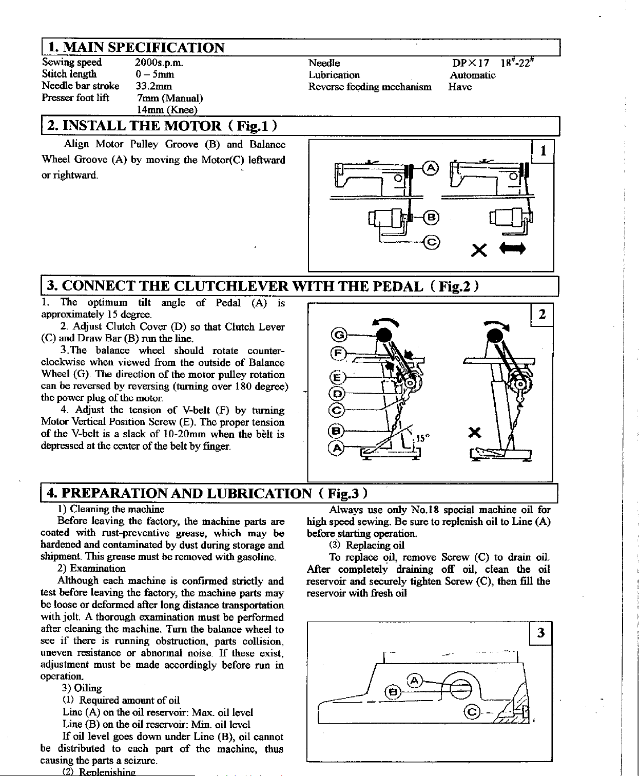
INSTALL THE MOTOR ( Fig.1 )
Align Motor Pulley Groove (B) and Balance
Wheel Groove (A) by moving the Motor(C) leftward
or
rightward.
2000s.p.m.
0-5mm
33.2mm
7mm (Manual)
14mm(Knee)
Needle
Lubrication
Reverse feeding mechanism
DPX
Auiomatic
Have
13. CONNECT THE CLUTCHLEVER WITH THE PEDAL ( Fig.2 )
1.
The optimum tilt angle
approximately
2.
Adjust Clutch Cover (D) so that Clutch Lever
(C) and Draw
3. The balance wheel should rotate counter-
clockwise when viewed from the outside
Wheel (G). The direction
can be reversed by reversing (tnrning over
the power plug
4.
Adjust the tension
Motor Vertical
of
the V-belt is a slack
depressed at the center
15
degree.
Bar
(B) run the line.
of
of
the motor.
Position Screw (E). The proper tension
of
10-20mm when the belt is
of
the belt by finger.
of
Pedal (A) is
of
Balance
the motor pulley rotation
180 degree)
of
V-belt (F) by tnrning
17 18'-22"
1
14. PREPARATION AND LUBRICATION ( Fig.3 )
l)
Cleaning the machine
Before leaving the factory, the machine parts are
coated with rust-preventive grease, which may
hardened and contaminated
shipment. This grease must be removed with gasoline.
2) Examination
Although each machine is
test before leaving the factory, the machine parts may
be loose
with jolt. A thorough examination must be performed
after cleaning the machine. Turn the balance wheel
see
uneven resistance
adjustment must be made accordingly before run in
operation.
be distributed to each part
causing the parts a seizure.
or
deformed after long distance transportation
if
there is running obstruction, parts collision,
or
3) Oiling
(1)
Required amount
Line (A) on the oil reservoir: Max. oil level
Line (B) on the oil reservoir: Min. oil level
If
oil level goes down under Line (B), oil cannot
2
by
dust during storage and
confirmed strictly and
abnormal noise.
of
oil
of
the machine, thus
If
these exist,
be
to
Always use only
high speed sewing.
before starting operation.
Ci)
Replacing oil
To
replace oil, remove Screw (C) to drain oil.
After
reservoir and securely tighten
reservoir with fresh oil
completely draining
--
__
No.l8
Be
sure to replenish oil to Line (A)
special machine oil for
off
oil, clean the oil
Screw (C), then fill the
-~.
Q:J_~---
l
--
©·-
/;.
...
Page 3
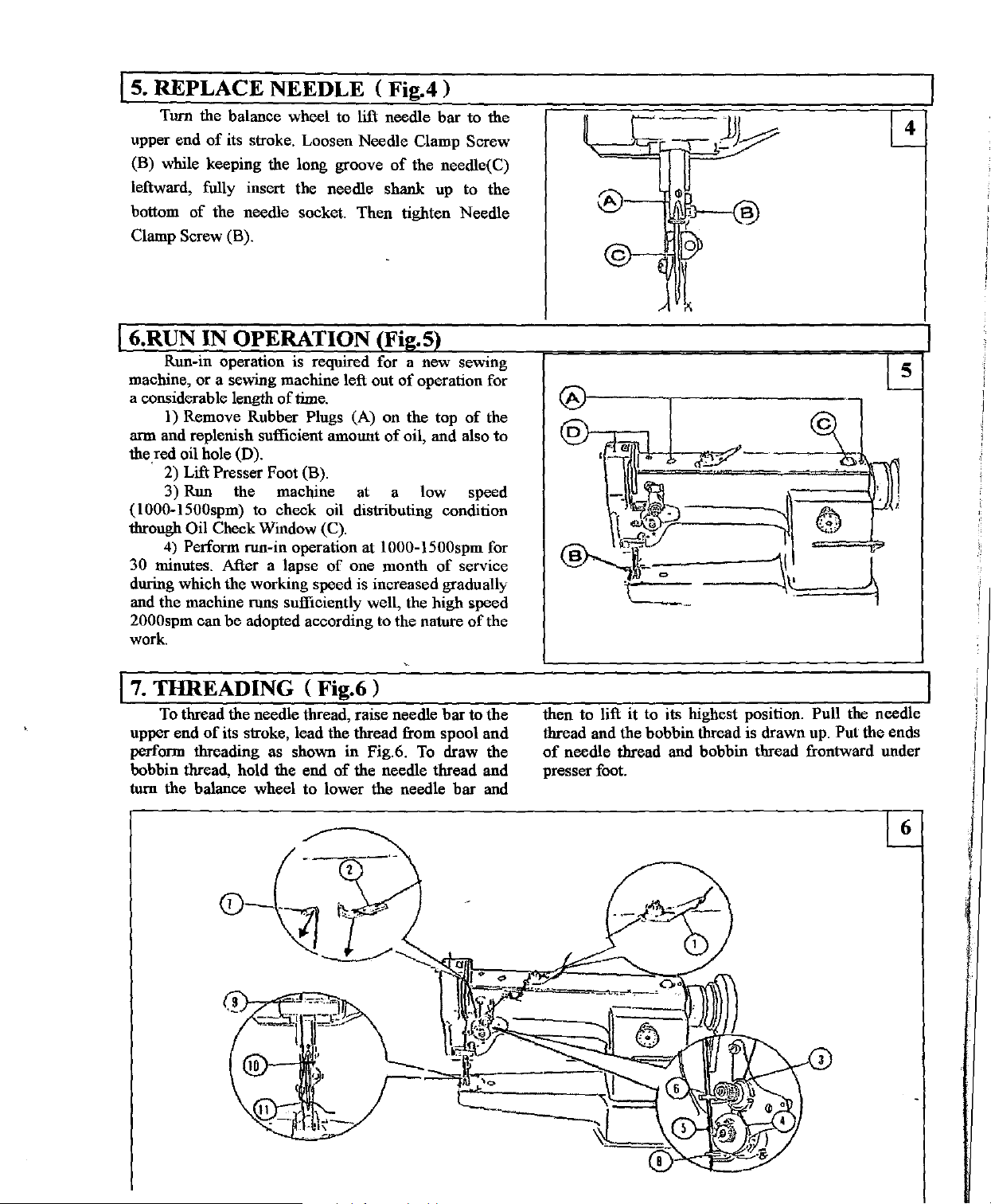
Is.
REPLACE NEEDLE <
Turn the balance wheel to lift needle
of
upper end
(B) while keeping the long groove
leftward, fnlly insert the needle shank up to the
bottom
Clamp Screw (B).
its stroke. Loosen Needle Clamp Screw
of
the needle socket. Then tighten Needle
Fig.4)
bar
of
the needle(C)
to the
I 6.RUN IN OPERATION (Fig.5)
Run-in operation is required for a new sewing
machine,
a considerable length
arm and replenish sufficient amount
the red oil hole (D).
(I
000-1500spm) to check oil distributing condition
through
30
during which the working speed is increased gradually
and the machine runs sufficiently well, the high speed
2000spm can
work.
or
a sewing machine left out
of
time.
I)
Remove Rubber Plugs (A) on the top
· 2) Lift Presser Foot (B).
3)
Run the machine at a low speed
Oil Check Window (C).
4)
Perform run-in operation at
minutes. After a lapse
be
adopted according to the nature
of
one month
of
operation for
of
oil, and also
I000-\500spm
of
of
service
of
the
to
for
the
I
7.
THREADING ( Fig.6 )
To thread the needle thread, raise needle
upper end
perform threading as shown in Fig.6.
bobbin thread, hold the end
tum
of
its stroke, lead the thread from spoo I
of
the needle thread and
the balance wheel to lower the needle
bar
To
draw the
then to lift
thread and
of
presser foot.
bar
to
the
and
and
·--L-=-
it
to its highest position. Pull the needle
the bobbin thread is drawn up. Put the ends
needle thread and bobbin thread frontward under
cv~~;;::..
Page 4
Is.
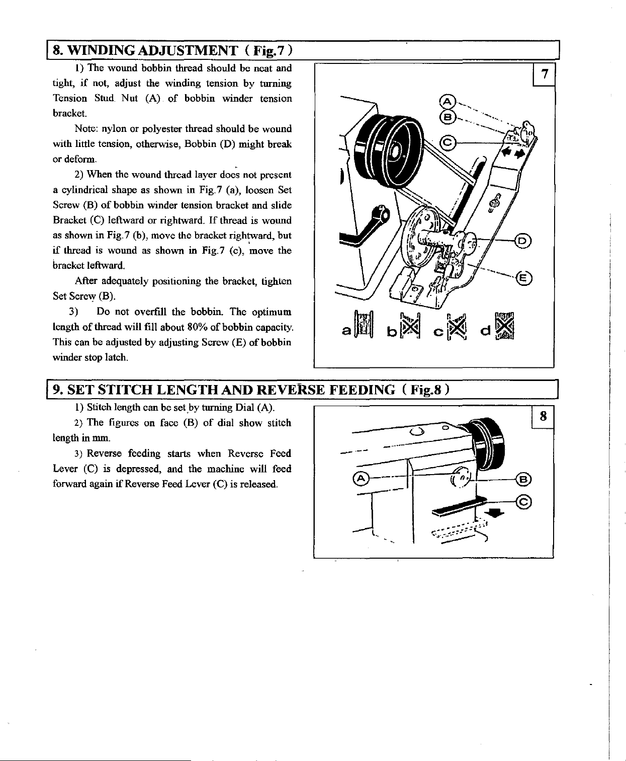
WINDING ADJUSTMENT <Fig.
I)
The wound bobbin thread should
if
tight,
Tension Stnd
bracket.
with little tension, otherwise, Bobbin (D) might break
or deform.
a cylindrical shape as shown in Fig.7 (a), loosen
Screw (B)
Bracket (C) leftward
as shown in Fig. 7 (b), move the bracket rightward, but
if
bracket leftward.
Set Screw (B).
length
This can be adjusted
winder stop latch.
not, adjust the winding tension
Nut
(A)
of
bobbin winder tension
Note: nylon or polyester thread should
2) When the wound thread layer does not present
of
bobbin winder tension bracket and slide
or
rightward.
thread is wound as shown in Fig. 7 (c), move the
After adequately positioning the bracket, tighten
3) Do not overfill the bobbin. The optimum
of
thread will fill about 80%
by
adjusting Screw (E)
be
neat and
by
turning
be
wound
If
thread is wound
of
bobbin capacity.
of
bobbin
1)
Set
----®
a~
19.
SET STITCH LENGTH
I)
Stitch length can be set
2)
The figures on face (B)
in
length
Lever (C) is depressed, and the machine will feed
forward again
mm.
3)
Reverse feeding starts when Reverse Feed
if
Reverse Feed Lever (C) is released.
_by
AND
turning Dial (A).
of
dial show stitch
REVERSE FEEDING (
Fig.8)
Page 5
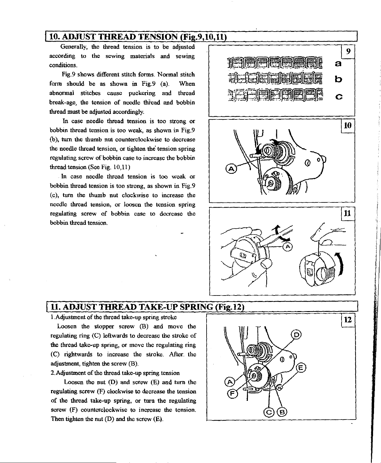
Ito. ADJUST THREAD TENSION (Fig.9,10,U)
Generally, the thread tension is
according to the sewing materials and sewing
conditions.
Fig.9 shows different stitch forms.
form should be as shown in Fig.9 (a).
abnormal stitches cause puckering and thread
of
break-age, the tension
be
thread must
In
bobbin thread tension is too weak, as shown
(b),
tum
the needle thread
regulating screw
thread tension (See Fig.
In
case needle thread tension is too weak or
bobbin thread tension is too strong, as shown in Fig. 9
tum
(c),
needle thread
regulating screw
bobbin thread tension.
adjusted accordingly.
case needle thread tension is too strong
the thumb nut counterclockwise to decrease
tension, or tighten
of
bobbin case
the thumb nut clockwise
tension,
of
needle thread and bobbin
10,11)
or
loosen !he tension spring
bobbin case
to
be adjusted
Normal
in
the
tension spring
to
increase the bobbin
to
increase the
to
decrease
stitch
When
or
Fig.9
the
9
a
b
c
ju.
ADJUST THREAD TAKE-UP SPRING
!.Adjustment
Loosen the stopper screw (B) and move the
regulating ring (C) leftwards to decrease the stroke
!he thread take-up spring, or move the regulating ring
(C) rightwards to increase the stroke. Mter. the
adjustment, tighten
2.Adjustment
Loosen the nut
regulating screw (F) clockwise to decrease the tension
of
the thread take-up spring,
screw (F) counterclockwise to increase the tension.
Then tighten the nut (D) and the screw (E).
of
the thread take-up spring stroke
the screw (B).
of
the thread take-up spring tension
(D)
and screw (E) and
or
tum
the
of
tum
the
regulating
(Fig.l2)
u
Page 6
j12.TIME NEEDLE MOTION TO HOOK MOTION (Fig.13,14)
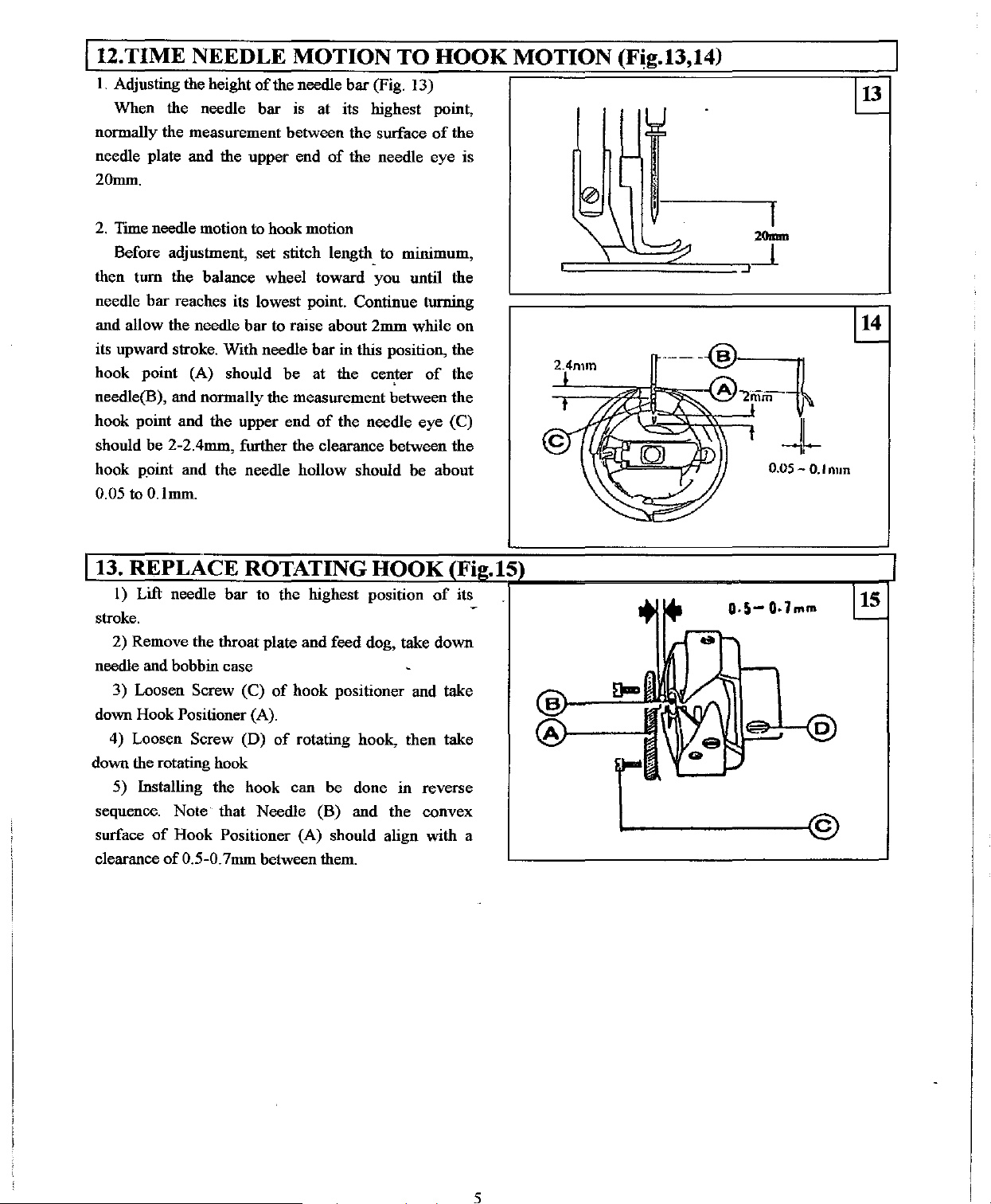
I.
Adjusting the height
When the needle
normally the measurement between the surface
needle plate and the upper end
20mm.
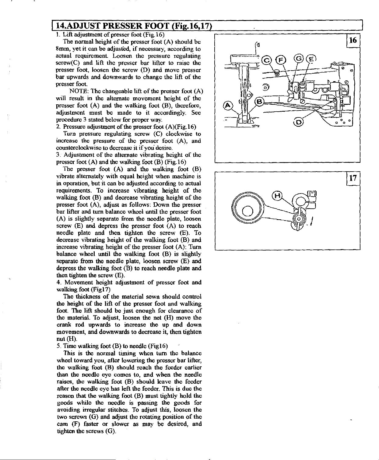
2.
Time needle motion to hook motion
Before adjustment, set stitch length_ to minimum,
then turn the balance wheel toward you
bar
needle
and allow the needle bar to raise about
its upward stroke. With needle
hook point (A) should be
needle(B), and normally the measurement between the
hook point and the upper end
should be
hook point and the needle hollow should be about
0.05 to O.lmm.
reaches its lowest point. Continue turning
2-2.4mrn, further the clearance between
of
the needle bar (Fig. 13)
bar
is
at its highest point,
of
the needle eye is
2mrn while on
bar
in this position, the
at
the center
of
the needle eye (C)
of
the
until the
of
the
the
0.05 - 0. I nun
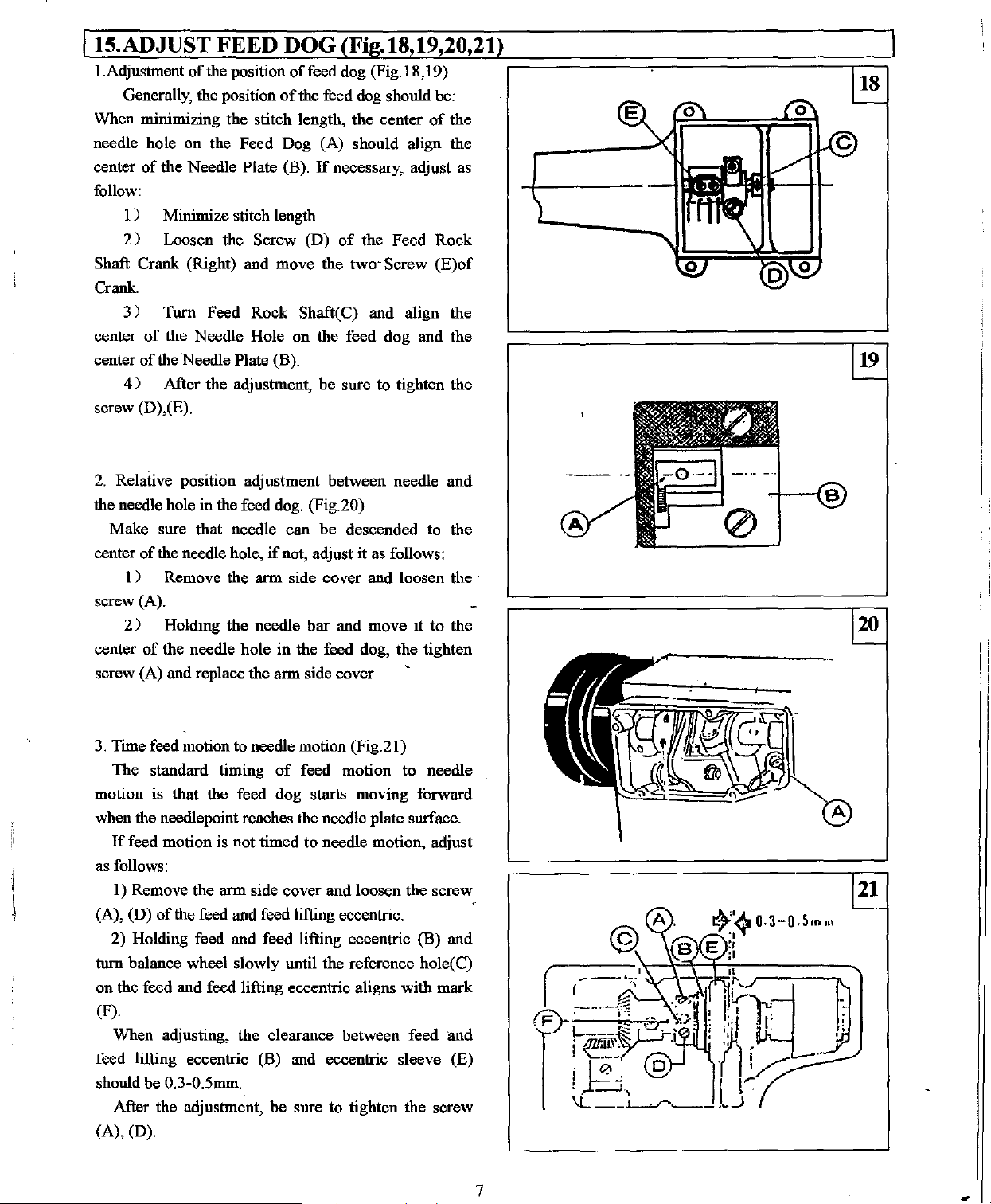
1) Lift needle
stroke.
2) Remove the throat plate
needle and bobbin case
3) Loosen Screw (C)
down Hook Positioner (A).
4) Loosen Screw (D)
down the rotating hook
5) Installing the hook can be done in reverse
sequence. Note that Needle (B) and the convex
of
surface
clearance
Hook Positioner (A) should align with a
of
bar
to the highest position
and
feed dog, take down
of
hook positioner and take
of
rotating hook, then take
0.5-0. 7mm between them.
of
its
[1---'
-©
Q.5-
Q.}mm
5
Page 7
lt4.ADJUST PRESSER FOOT (Fig.l6,17)
1.
Lift adjustment
The normal height
8mm,
yet
it
actual requirement Loosen the pressure regulating
screw(C) and lift the presser
presser foot, loosen the screw (D) and move presser
bar
upwards and downwards to change the lift
presser foot.
NOTE: The changeable lift
will result in the alternate movement height
presser foot (A) and the walking foot (B), therefore,
adjustment must
procedure
2.
Pressure adjustment
Turn pressure regulating screw
increase the pressure
counterclockwise to decrease it
3. Adjustment
presser foot (A) and the walking foot
The presser foot (A) and the walking foot
vibrate alternately with equal height when machine is
in operation,
requirements. To increase vibrating height
walking foot
presser foot (A), adjust as follows: Down the presser
bar lifter and
(A) is slightly separate from
screw (E) and depress the presser foot (A) to reach
needle plate and then tighten the screw
decrease vibrating height
increase vibrating height
balance wheel until the walking foot
separate from the needle plate, loosen screw (E) and
depress the walking foot
then tighten
4.
Movement height adjustment
walking foot
The thickness
the height
foot. The lift should be
the material.
crank rod upwards to increase the up and down
movement, and downwards to decrease it,
nut (H).
5.
Time walking foot (B) to needle
This is
wheel toward you,
the walking foot (B) should
than the needle eye comes to,
raises, the walking foot (B) should leave the feeder
after the needle
reason that the walking foot (B) must tightly hold the
goods while the needle is passing the goods for
avoiding irregular stitches. To adjust this, loosen
two screws (G)
cam
tighten the screws (G).
3 stated below for proper way.
(F) faster
of
presser foot (Fig.l6)
of
the presser foot (A) should
can
be adjusted,
be
of
the alternate vibrating height
but
it can
(B)
and decrease vibrating height
if
necessary, according
bar
lifter to raise the
of
the presser foot (A)
made to
of
the presser foot (A)(Fig.l6)
of
be
adjusted according to actual
it
accordingly. See
(C) clockwise
the presser foot (A), and
if
you
desire.
(B)
(Fig.l6)
of
of
tum balance wheel until the presser foot
the
needle plate, loosen
(E). To
of
the walking foot
of
the presser foot (A): Turn
(B)
to
reach needle plate and
the
screw (E).
of
presser foot and
(Figl7)
of
the material sewn should control
of
the lift
To
the
of
the presser foot and walking
just
enough for clearance
adjuSt, loosen the net
(Figl6)
normal timing when tum the balance
after lowering the presser
reach
the feeder earlier
and
when the needle
eye
has left the feeder. This is due
and
adjust the rotating position
or
slower as may be desired, and
(B)
(H)
then
(B)
is slightly
move the
tighten
bar
of
the
the
of
the
(B)
the
of
the
and
lifter,
of
be
to
to
of
the
the
the
Page 8
I15.ADJUST FEED DOG(Fig.18,19,20,21)
!.Adjustment
Generally,
When minimizing the stitch length, the center
needle hole on the Feed Dog (A) should align
center
follow:
l)
2)
Shaft Crank (Right) and move the two- Screw
Crank.
3)
center
center
of
4)
screw (D ),(E).
2.
Relative position adjustment between needle
the needle hole in the feed dog. (Fig.20)
Make sure that needle
center
of
l ) Remove
screw (A).
2 ) Holding
center
screw (A) and replace
of
the position
the position
of
the Needle Plate (B).
Minimize stitch length
Loosen the Screw (D)
Turn Feed Rock Shaft( C) and align the
of
the Needle Hole on the feed dog and the
the Needle Plate (B).
After the adjustment, be sure to tighten the
the needle hole,
the arm side cover and loosen the ·
the needle
of
the needle hole in the feed dog, the tighten
of
feed dog (Fig.l8,19)
of
the feed dog should he:
lf
necessary, adjust as
of
the Feed Rock
can
be
descended to the
if
not, adjust it as follows:
bar
and move
the arm side cover
it
of
the
the
(E)of
and
to
the
3.
Time feed motion to needle motion (Fig.2l)
of
The standard timing
the feed dog starts moving forward
the feed and feed lifting eccentric.
0.3-0.5mm.
I
I
motion is that
when
the needlepoint reaches the needle plate surface.
lf
feed motion is not timed to needle motion, adjust
as follows:
l)
Remove the arm side cover and loosen the screw
(A), (D)
turn balance wheel slowly until
on
(F).
feed lifting eccentric (B) and eccentric sleeve (E)
should be
(A),
of
2) Holding feed and feed lifting eccentric (B) and
the feed and feed lifting eccentric aligns with mark
When adjusting, the clearance between feed lltld
After the adjustment, be sure to tighten the screw
(D).
feed motion to needle
the
reference hole(C)
7
21
Page 9
lt6.
REGULAR CLEANING (Fig.22,23)
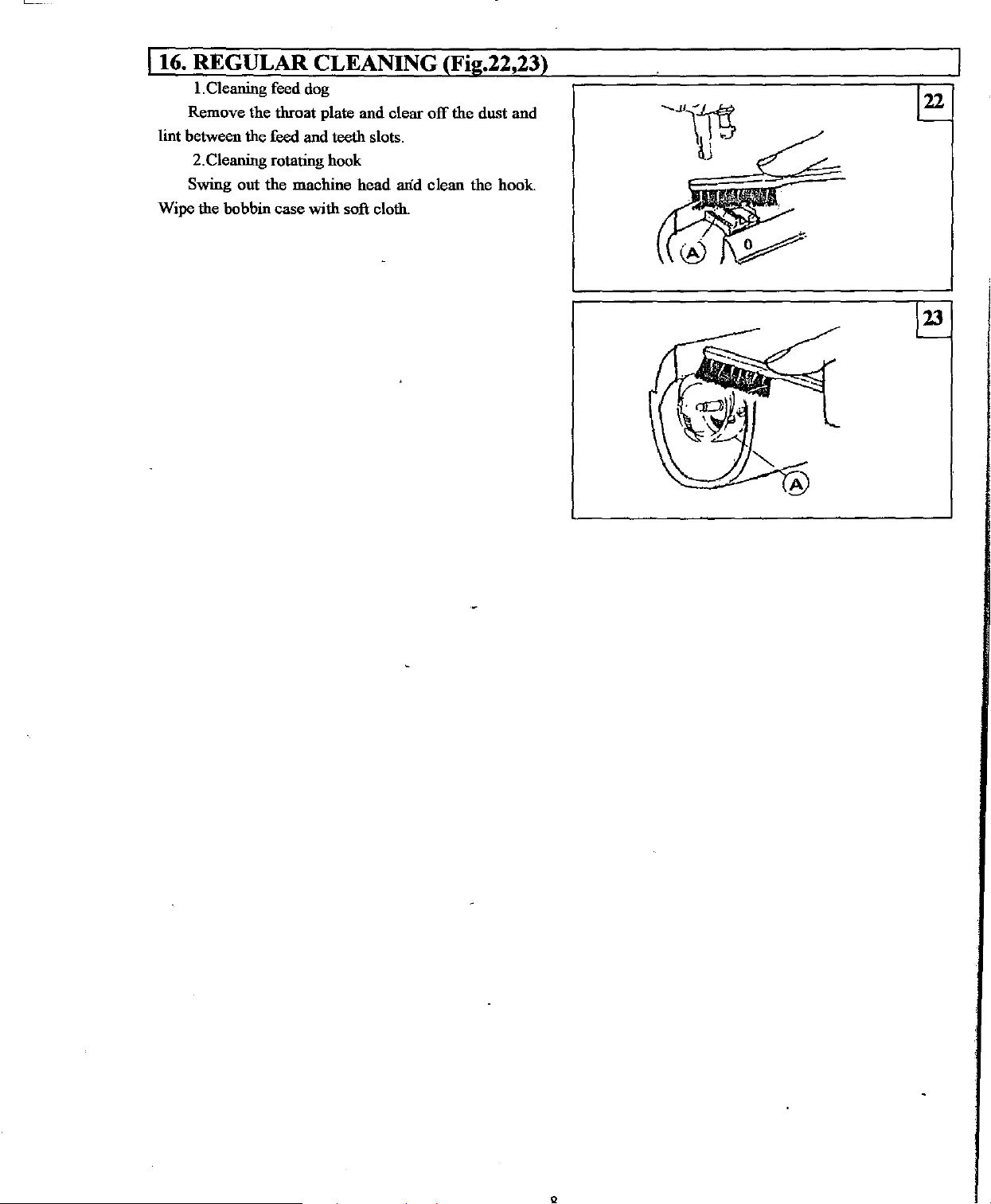
1.
Cleaning feed dog
and
clear
Remove the throat plate
lint between the feed and teeth slots.
2.Cleaning rotating hook
Swing out
Wipe the bobbin
the
case
machine
with
head
soft cloth.
off
arid clean the
the
dust
and
hook
Page 10
PARTS
LIST
Page 11

1.
ARM
BED
AND
ITS
ACCESSORIES
Page 12

1. ARM BED AND ITS ACCESSORIES
No.
I.
2.
3.
4. GB827-86
5.
6.
7.
8.
'
9.
10.
II.
12. 05-01-014
13. 05-01-015
14.
15.
16.
17.
18.
19.
20.
21. GB896
22.
23.
24.
25.
26.
27.
28.
29.
30.
31.
32. 05-01-007C7
33.
34. 05-01-007C8-2
35.
36.
37.
38.
39.
40.
41. 05-01-009
42. 05-01-010
43. 05-01-011
44.
45.
46. 01-01-006
47.
48.
49.
50.
51.
52.
53.
54.
55.
56.
57.
58.
59.
Ref. No.
05-0l-OOIA2
09-01-00 I B2
09-01-002
05-01-003
05-01-004
05-01-005
05-01-006
22TI-003C5
05-0J-013
22TI-003C6
Ann
Ann bed
Trade mark plate I
Trade mark plate rivot 2
Faceplate
screw 1
Set
Knock pin I
Thread guide (Up) I
Thread guide (Middle) I
Thread guide (Lower) 1
Set
screw
Description Pes
Ann side cover 1
Gasket for arm side cover I
72TI-017
12H1-007C1 Oil check window 1
12HI-007C2
22Tl-009El
22TI-009E2
22Tl-009E3
22Tl-009E4
22Tl-009E5
22Tl-010
22Tl-Oll
05-0I-007C1
05-0l-007C2
05-01-007C3
73Tl-002C1
05-0 1-007C4
05-01-007C5.
05-0 1-007C6
05-01-007C8-1
05-0 1-007C9
05-01-007C10
05-01-007Cil
05-01-007C12 Thread tension release pin 1
72Tl-013
05-01-008
05-01-016
22Tl-Oil
01-01-007
72Tl-017
09-01-003
72Tl-004C4
72Tl-009
72Tl-Oil
09-01-004
09-01-005
09-01-006 Bed
09-0l-007
72Tl-017
72Tl-017
22Tl-Oil
Set screw
0-ring
Screw type tension stud I
Spring for pretension I
Disc for pretension 2
Space for pretension 1
Stop ring I
Pretension tluead guide 1
Three-hole tluead guide 1
Set screw
Thread tension bracket
Thread tension stud 1
Tension regulating
Thread tension spring 1
Thread tension releasiiig disc
Thread tension disc 2
disc 1
Stop
Pin
Thread controller disc
Thread controller plate 1
Screw
Thread tension release plate
Screw
Screw
Thread controller stud
Thread take-up spring 1
Tension thumb nut 1
Thread take-up spring stup 1
Screw
Screw
Bed side cover I
Gasket for bed side cover
Set screw
Cap for bed face plate I
Rubber plug 8
Rubber ping
Rubber ping
Bed cover
Gasket for bed cover 1
rear
cover 1
Gasket for bed
Set screw 4
Set screw
Screw
-
rear
nut
cover
Remarks
I
1
1
3
8
1
1
1
1
1
1
1
1
1
2
1
1
I
1
1
6
I
I
I
1
4
l
Page 13

2.
NEEDLE
BAR
AND TAKE-UP
MECHANISM
··v
Page 14

2. NEEDLE BAR AND TAKE-UP MECHANISM
No.
1.
2.
3.
4.
5.
6.
7.
8.
9. 22T2-007
10. 05-02-006
11.
12. 05-02-007
13. 05-02-008
14.
15.
16.
17.
18. 05-o2-009B3
19.
20. 72T2-003
21.
22.
23. 22T2-002
24. 05-02-012
25.
26. 04-02-005
27.
28. 22T2-017
29.
30. 02-08-007
31. 09-02-00 I C2
32. 22T5-001A4
33.
34. 05-02-015 Bushing for rock shaft (Left) 1
35.
36.
37.
Ref. No.
05-02-001
05-02-002
22T2-002
05-02-003 Thread take-up lever driving stud l
05-02-004
22T8-0llC4
05-02-005Al
22T2-006
72T2-004B2
22T7-0I5
05-02-009Bl
05-02-009B2 Crank (Left) 1
GBI17
05-02-009B4
05-02-010
05-02-0ll
04-02-004 Thread guide for needle
05-02-014Cl
05-05-003 Hinge pin (Upper) 1
05-02-016
22T2-002
22Tl-Oll
Thread take-up lever 1
Hinge pin l
Set screw
Oil guard
Set screw
Needle
Set screw
Set screw
Hinge
pin
Set screw
Needle
Needle
Set screw
Needle
Pin for crank
Slide block for needle
Position bracket
Screw
Needle
Hinge
Screw I
Needle
Screw
Needle
Needle clamp screw - I
Crank (Right) I
Screw
Crank level-link
Screw
Bushing for rock shaft (Right)
Screw
Screw
bar
bar
pin
(Right) 1
Description
bar
crank 1
bar
link 1
adaptor I
rock frame rock shaft
bar
rock frame
bar
rock frame I
bar
bar
Pcsl
Remarks
1
1
l
1
1
2
1
1
I
l
1
I
1
1
1
1
1
1
1
1
2
I
Page 15

3.
ARM
SHAFT
AND
VERTICAL
SHAFT
MECHANISM
~~
@
Page 16

3. ARM SHAFT AND VERTICAL SHAFT MECHANISM
No. Ref. No.
1.
05-03-00lAl
22T3-001A2
2.
22T6-005Bl
3.
4.
22T3-002B2
5.
22T3-003
6.
05-03-007
22T7-002
7.
8.
05-03-006 Ann shaft bushing (Right) 1
9.
22T3-006F
10. 02-03-001
11.
22T3-007C2
22T3-008
12.
09-03-00 I B 1
13.
14.
22T2-002
15.
09-03-001
16.
04-01-017
17.
09-03-00 1B2
22Tl-Oll
18.
19.
05-03-003
20.
21.
22. 22T2-005B3
23.
24.
25.
26.
27.
22T3-010E2a1-2
22T3-0l
22T3-010E2b1-2
22T3-0 1 OE2b2-2 Bevel
05-03-004 Vertical shaft bushing (Upper)
05-03-005
22T2-002
B3
OE2a2-2 Bevel
Description
Pcsl
Ann shaft 2
Rubber plug
Collar for arm shaft
screw 1
Set
Ann shaft bushing (Left) 1
Ann shaft bushing (Middle)
Set
screw
seal
Oil
Balance
Set
Set
Feed lifting eccentric 2
Set
Baflle plate 3
Set
Feed
Screw
Vertical shaft 1
Bevel gear for arm shaft 1
Set
Bevel
Vertical shaft bushing (Lower) 2
Set
wheel
screw 1
screw
screw
screw
link lever 1
gear
for vertical shaft (Upper)
screw
gear
for hook shaft 1
gear
for vertical shaft (Lower)
screw
-
Remarks
1
2
1
1 .
1
2
1
1
1
1
8
1
1
1
-
15
Page 17

4.
HOOK
SHAFT
MECHANISM
Page 18

4. HOOK SHAFT MECHANISM
No.
l.
2.
3.
4.
5.
6.
7.
8.
9.
10. 09-04-002Al
11.
12.
13.
14.
15.
16.
Ref. No. Description
09-04-001
09-04-007
09-04-008
22T4-001Alal
22T4-001Ala2
05-04-003
22T4-017
09-04-004
09-04-009 Hook shaft bushing (Right) I
22Tl-Oll
09-04-006
22T6-001Alb
09-04-003
09-04-005
Pes Remarks
Rotating hook shaft 1
Bearing block 1
Set screw
Filter screw 1
Filter 1
Rotating hook complete
Bobbin case 1
Bobbin
Collar for hook shaft (Left) 1
Collar for hook shaft (Right)
Set screw 2
Hook shaft bushing (Left) 1
Set screw 2
Rotating hook positioner
Set screw 2
4
1
1
1
1
I
ji
II
-
-
17
Page 19

5.
STITCH
LENGTH
REGULATING
t.---
MECHANISM
If\
\Y
---
...;----
---
----
....
'
....
_:::..
18
Page 20

5.STITCH LENGTH REGULATING MECHANISM
No. Ref. No.
09-05-003
I.
2.
09-05-001 Hinge pin
3.
GB896
4.
-05-06-003
22Tl-Oil
5.
08-05-002BI
6.
22T2-0I9
7.
05-06-001
05-06-005
8.
9.
09-05-002
IO.
12.
13.
14.
15.
16.
17.
18.
19.
20 ...
21.
22.
23.
24.
25. 22T5-012E1a1
26.
27.
28.
29.
72T5-003
ll.
04-06-002
22T5-006C4
22T5-006C2 Dial I
22T5-006C3
72T5-005
22T5-008
22T5-009
72T5-006CI Reverse feed lever 1
05-06-002D I
1
22T5-0
22T5-010D3
22T5-001A4
22T5-0il
22T5-012EI
22T5-012E1a2
22T5-012E2
22T5-013
22T5-014
OD2b
Description
Reverse feed link lever I
Retaining ring I
Bushing for reverse feed lever shaft 1
Set screw I
regulator 1
Feed
screw
Set
Feed regulator bushing 1
Set screw
Hinge pin for feed regulator I
Rubber plug
Feed regulator screw bar I
0-ring
Screw
Rubber plug 1
Stopper pin
Spring
Reverse feed lever shaft 1
0-ring
Screw
Screw
Washer
Reverse feed crank 1
Slide block pin
Slide block 1
Spring
Screw
Bracket for spring
for stopper pin 1
for reverse
fe"t:d
crank 1
Pes
2
2
Remarks
1
I
1
I
1
1
1
1
1
1
I
I
.
Q
Page 21

6.
FEED
LIFTIN
GMECHANISM
20
Page 22

6.FEED LIFTING MECHANISM
No.
I.
2.
3.
4. 09-06-003 B I
5.
6.
7.
8. 09-06-005
9. 09-06-019
10. 09-06-006
ll.
12. 09-06-007
13.
14. 09-06-009
15. 22T5-0IOD3
16.
17. 09-06-0
18.
19. 09-06-011 C3
20. 09-06-012
21. 09-06-013
22.
23.
24.
25.
26.
27.
28.
29.
30. 09-06-018
31.
32. 09-06-022
33. 09-06-021
34. 22T1-011
35.
36.
37.
38. 09-06-023
39.
40.
41.
42.
43. 09-06-017
Ref. No. Description
09-06-00
09-06-00IA2
09-06-002
09-06-00382
09-06-004
04-01-017
09-06-020
09-06-008
09-06-010
09-06-0l!C2
22Tl-Oll
09-06-014
09-06-015
22T6-001Alb
08-03-004014
22T1-0ll
09-06-016
22Tl-Oll
08-03-00407
08-03-004012
08-03-00409
08-03-00408
01-04-00282
22TI~OO!A9
08-03-004010
08-03-004011
ll
lAl
c 1
Pes
Feed
bar
bracket I
Stud bushing 1
Set
screw
Needle plate bracket 1
Screw 4
Needle plate 1
Screw 2
Feed dog 1
Screw·
Hinge
pin
Screw 2
Piping unit bracket 1
Spring
Washer I
Screw 1
Binder positioner
Piping unit base-plate I
Pin for belt 9
Screw
Feed rock shaft crank (Left) 1
Slide
Screw 2
Feed rock shaft I
Feed rock shaft crank (Rigbt) I
Screw
Short
Crank (Lower) 1
Set screw
Hinge pin •
Feed regulator
Hinge pin (Long) 1
Hinge pin (Short) 1
Screw 2
Crank link lever (Long) 2
Crank link lever (Short) 2
Eccentric shaft I
Collar for feed rock shaft (Left) 1
Screw 2
Pin for crank link lever (Short) I
Pin for crank link lever
Collar for feed rock shaft (Rigbt)
for
piping unit bracket 1
bar
pin
for
crank link lever 1
Screw
Screw 4
-
crank
2
2
2
2
Remarks
1
1
I
I
I
1
1
I
I
Page 23

7.
PRESSER
FOOT
MECHANISM
'
'
Page 24

7.PRESSER FOOT MECHANISM
No.
l.
2. 05-07-002
3.
4.
5.
6.
7.
8.
9.
10.
11.
12.
13.
14. 05-07-021
15.
16. 05-07-013
17. 05-07-014
18. 05-07-015
19. 05-07-016
20. · 22T7 -005-001
21. 05-07-017
22. 05-07-018
23.
24.
25. 05-07-019
26.
27. 05-07-022
28.
29.
30. 05-07-011
31. 22T2-002
Ref
No.
05-07-001
05-07-003
05-07-004
05-07-005
05-07-006
22T2-001A9
05-07-007
22T6-008-D3
05-07-008
05-07-009Al
05-07-009A2
05-07-010
09-07-001
22T9-001A9
22T9-00
05-07-020
02-08-007
05-07-023
lAl
Description
Presser foot lifter l
screw 1
Set
Presser
Presser bar bushing (Upper)
Presser
Presser
Screw
Presser
Screw
Presser
Tbread tension release slide
Pin for thread tension release slide 1
Bracket for presser
Screw I
Out presser foot 1
Screw
Presser
Screw
}Cneelil\erliftinglever
Screw
Retracting spring for lever 1
Retracting spring bracket 1
Screw
0
Nnt
Pressure regulating screw 1
Thread
Presser
Screw
Pin
Presser bar bushing (Lower) I
Screw
bar
position guide 1
bar
bar
position guide bracket 1
bar
lifting bracket 1
-
bar
spring I
bar
spring 1
bar
spring (Flat) 1
tension release pin
bar
lifting bracket guide 1
Pes· Remarks
I
1
1
I
I
I
1
1
1
1
1
I
1
1
3
I
I
Page 25

8.
PRESSER
LIFTING
MECHANISM
Page 26

8. PRESSER LIFTING MECHANISM
No. Ref. No. Description
05-08-00IAI
1.
22T3-002B2
2.
3.
05-08-00
05-08-00IA3
4.
5.
GB893
05-08-00281
6.
7.
05-08-00282 Set screw
8.
05-08-003 Screw for lifting eccentric connecting collar
05-08-004 Lifting eccentric connecting collar
9.
10.
II.
12.
13.
14.
15.
16.
17.
18.
19.
20. 05-08-013 Vibrating presser
21.
22.
23.
24.
25.
26.
27.
28.
29.
30. 05-08-021
31.
32.
33.
05-08-005
05-08-006
05-08-007 Lifting rock shaft
02-08-004 Lifting rock shaft bushing (Right)
22Tl-Oll
05-08-008
05-08-009
05-08-010 Lifting bell crank link
05-08-011
05-08-012
.
09-08-001
22T2-004
05-08-015
05-08-016
05-08-017
05-08-018
22T2-00IA.9
05-08-019 Slide block for vibrating presser
05-08-020
22T2-004
GB97
05-08-022
IA2
Lifting eccentric
Screw
Lifting eccentric connection
Needle bearing
Retaffiing ring
Adjusting crank for eccentric connection
Washer
Nut
Screw
Hinge pin
Hinge pin nut
Lifting
Presser lifting
Vibrating presser foot
Screw
Vibrating presser
Spring guide rod
Adjusting bolt
Guide for slide block
Screw
Screw
Oil seal plate
Screw
Washer
Lifting rock shaft bushing (Left)
bell crank
link
bar
bar
spring
bar
Pes
1
2
I
1
1
1
I
I
I
I
I
I
I
2
I
1
I
I
I
I
I
I
I
I
I
I
2
I
I
I
1
I
I
Remarks
' \
'
25
Page 27

9. LUBRICATING
MECHANISM
3
r-----,
'
'
I
'
I
I
I
I
I
I
I
L-------J
26
Page 28

9.LUBRICATING MECHANISM
No.
1.
2.
3.
4.
5.
6.
7.
8.
9. 22T4-007C2 Pipe connection
10.
11.
12.
13. GB70
14.
15.
16.
17.
Ref. No.
Ol-08-00IA2 Oil pump shaft I
01-08-00 IA3
Ol-08-00IA4
Ol-08-00IA5 Gear for oil pump (I) I
OI-08-00IA6 Gear for oil pump (II) I
Ol-08-00IA7
11H8-008B
11H8-0IO
01-08-002
22T2-0I9 Screw 3
22T2-019
72T8-002Bl Oil pipe I
05-09-001 Oil pipe for arm shaft I
OI-08-004 Pipe holder for arm shaft I
72T2-003
Oil pump body
pump body (II)
Oil
pump cover
Oil
pump screen
Oil
Set screw
Oil pump
Set screw
Set screw
Set screw
body plate
Description Pes
(!)
3
3
3
3
Remarks
I
I
I
I
1
I
-
-
27
Page 29

lO.OIL
RESERVOIR
AND
OTHER
ACCESSORIES
28
Page 30

10. OIL RESERVOIR AND OTHER ACCESSORIES
No.
I.
2.
3.
4.
5.
6.
7.
8.
9.
10.
ll.
12.
13.
14.
15. 22T9-003B2
16.
17.
18
19
20
21
22
23
24
25
26
27
28
29
30
31
32
33
34
35 Chain I
36
Ref. No. Description
01-09-001 Oil reservoir I
GB70 Screw 4
01-09-002
01-09-003 Oil window I
22T9-00IA2
22T9-001A3
22T9-003Bl
01-09-005
05-10-001
GB896
22T9-00IA7
22T9-00IA8
22T3-007C2 Screw I
22T9-00IA9
22T9-00IAIO
22T9-003B3
72T9-0\8
22T9-003B5 Knee lifter plate I
22T9-003B6
22T9-003B7 Set screw 1
22T9-003B8
01-09-006
01-09-007
01-09-008 Bracket (3
01-09-008 Bracket (294) I
GB93 Washer
GB52
GB12 Screw 4
GB93 Washer 4
GB52
GB70
05-10-003
05-10-002 Knee lifter
GB84-88 . Set screw 2
05-I0-004a
05-10-004 Chain hook I
Gasket
Oil drain
Washer 1
Oil-proof cover I
Knee lifter
Hinge
Stop ring I
Retracting spring for knee lifter I
Knee lifter stop
Adjusting
Locknut
Knee
Joint for knee lifter bell
Set
Bracket for knee lifter plate I
Pad
Rubber
Pin
for oil reservoir I
screw
bracket
pin
for
knee
lifter
bracket
screw
lifter bell
screw
for knee
cushion
24)
crank
crank
lifter
plate I
-
Nut
Nut
Screw
Plate for knee liftei bracket
rod
crank I
Chain hook (Upper) I
Pes Remarks
I
I
I
I
2
2
I
I
2
4
4
I
4
4
4
4
I
-
Page 31

11. ACCESSORIES
No. Ref.
72T9-022
I.
22T9-017
2.
22T9-018
3.
01-09-009
4.
5.
22T9-0ll
6.
22T9-012
7.
72T9-007
8.
72T9-020
9.
10. 72T9-021
No.
Double-end wrench
Oil
container
Vinyl cover
Wrench
Needle
Oiler
Magnet
Screw driver (Long)
Screw
driver ( Medium)
Screw
driver (Short)
Description
Pes
Remarks
I
I
I
I
4
I
I
I
I
I
Page 32

12. BOBBIN WINDER MECHANISM
'
.•'
.·
--
I
No. Ref. No.
I.
22T9-006Dl
22T9-006D2
2.
22T9-006D3
22T9-006D4
3.
22T9-006D5
22T9-006D6
4.
5.
22T9-006D7
6.
22T9-006D8
7.
22T9-006D9
8.
22T9-006Dl
9. 22T9-006D
10. 22T9-006D 12
ll.
22T9-006Dl3
12.
13.
14.
20. 22T9-006D22
21.
22.
23.
15.
16.
17.
18.
19.
22T9-006Dl4
22T9-006Dl5
22T9-006D 16
22T9-006D 17
22T9-006Dl8
22T9-006D19
22T9-006D20
22T9-006D21
22T9-006D23
0
11
®
~
~
e "
1
@
Bobbin winder base
Bobbin winder arm
Shaft
Spring
Bobbin winder spindle
Bobbin winder pulley
Screw
Bobbin winder stop latch lever
Bobbin winder connecting
Rivet
Screw
Bobbin winder stop latch
Adjusting screw
Stopper block 1
Fixture for stopper block
Set screw 1
Bobbin winder tension bracket 1
Bobbin winder tension stud
Bobbin winder tension disc
'
Tension stud bushing
Bobbin winder tension spring
Tension stud nut
Tension bracket screw
Wood screw
Washer
~
-~
for bobbin winder arm
...........
•.•
--.,
Description
.
.......
__
bar
__
Pes Remarks
1
1
1
1
1
1
1
1
1
2
1
I
1
1
1
2
I
1
1
1
2
2
 Loading...