

Page 1

•
ta
IJL
• m
~
~
.
..
• ·I .
••
···
-..,
~~J
ZJ24028-1/ZJ24028
-2
if
OPERATION
•
PA R
mist
itt:
TS
an~
lVlANUAL
=f.
BOO
It
K
Ul
Iii·
UJ
II
fil
ZOJE
SEW
ING
tiJI
MAC
iT
ifl
ft~
H IN E
fR
Jli
CO
Be
Z!
.• L TO
81
.
Page 2

INSTRUCTION
MANUAL
FOR
POST-BED
This manual is prepared to permit the sewing machine to be
This machine is
leather works.
Being
eq
uipped with spring
type thread take-up provides perfect
post-bed
You
can either select
industrial sewing machine suitab
1-n
.eedle or 2-oeedle machine accordi
return
reverse lever
uoif
omed
rype
stitching.
- i
NDEX-
feed mechanism opener
IN
DUSTRIAL SEWING
used
efficiently and for highest performance.
le
for sewing sboes, bags, caps and general
og
to your
type
type
vertical hook, and slide
MACHINE
of
works.
Specification
Main
parts
Preparation f
L
1).
Place
2)
. How
3).
How
4). How
5). How to
6). !low
7).
How
8). How to mount the vibration
U. Preparation f
I). Selection
2). How
3
).
How
4
).
How to wind
5).
How to adjust the bobbin winder asscmbly
6)
.
How
m.
Bow
1).
2).
...................
name
of
machine
or
installation
of
installation
to
mount the machine head
to
mount the motor ..
to
COillleet
moun
to
mount
to
mount
to
to
lead the upper thread
to place
to operate
Starting
Sewing over
the
t the bobbin winder assembly
and
adjust
the
oil
or
operation
of
thread
attach the oc:edle
the
lower thread on the bobbin ...
the
bobbin into the hook
.....
to
sewing
...............
.....
...................................................................................
head
of
machine ............................
of
machine
...........................................................
motor
lever and
th
e knee lifter mechanism .......
pan. .................................
preventi.r.~
..........................................................................................
..............
...... ......
.......
...
....
.................
...
................................................
.....
..
...............................
......................................
................................................. , ...............................
.......•....
..............
..............
......
...............
.........
....
......
.......
............ , ....................................
foot
pedal .••.•..•
rubber .....
......
...
.......
..........
...
...........
.............•.
...
.....
...
....
....
.........
.
.....................................•.................
..............
.........
...
......
.............
................
.......................................
...
.. :
.........
.....
...
...................
.........
.......... , .......
....
...
.......................................
.......
....
............................................
..............
.....
.....
.......
.....................
•••••.•.•.•.•.•..
.........
...
...................
.........
.......
........
...
......
....
....
...
...
.....
.....
...................................
..... .
.......•
••.•.•••••••... 4
...........................
...
....
.........
........
..........
.....
...
...................
....
..........
..................
...............
..
......
........................... l3
........................................
.........
.................
...
...
.........
.......
...
......
.....
......
....
..
.
. 2
3
.4
4
.4
.4
.4
. 5
6
6
7
7
. 7
8
9
IO
11
13
13
IV. Stitching adjustment
1
).
Adjustment
2).
Forward and Reverse stitching
3).
Adjustment
4). Adjustment
5). Propef ti
ming
6). Proper timing between the book and opener
7). Proper timing between the
V.
Cleaning
1).
Oeaning
2).
3). Grease ................
Lub
and
Lubrication
...........................
rication
...
....
.....
...
of
stitch length
of
thread !etlsion
of{ccd
dog height and pressure of
between the hook
.....................
....
...................
.........
.....
......................
...............
........
.................................................................................
........
...
........
....
.....
.......
.................
...
........................................................................
and
needle .
pre.sse;-
......
on
...
..............
materials
.....................................................
feed
dog
and
needle
...
....
..................................................
...
...............................................................
..
..................................................................
.....
......................................................
..........
........
....
......
..................
............................
.....
...............
.................................
....
.............
....
...
...
, .. ,
...................
......
........
.........
....
..
........
.......
.....
....
..
...
......
......
....
14
14
14
! 4
17
18
21
22
23
23
23
24
Page 3

• Specification and ma
in parts name
of
machine head.
• sPECIFICATI
Sewing materials
Speed
... .
............
Nudle
...........
Nudle
Thread
Stitch lenglh .
bar stro
take
up
.......
Pres~cr
bar
stroke
Pre~
fool.
•........
ke
.•..
ON
...... Shoe
...
....
...... 33.4
.....
....
.••.•.
s,
Bags,
works.
.. 3000
..
RPM.
OP
x S
(13
5 x 5)
mm (1-5
Stide lype
0-Smm(0
8mm
1-Nudle
1-l'\eedlc(Ul6")RoUcr foot
2-Needle( l/4")
(51l
- 3/16")
6")
......
Caps
, and lealbcr
/16")
Roller foot
Usual
foot
Hook. ..
Stitch lenglh adjuslment... Dial regulatOr type
Reverse stitching......... .. . Spring rerum manual lacker
Post beigbt. .. .. . .
Lubrication
Oil circulation
Knee
Table.......
Moto
.......
....
....
•.................
.........
mecbanism...
.................
r..
.......
. . . . . . . . . . . . .
.........
..
. . . . . . .
Vertical book wilh opener
..
178mm(7")
Manu
two
......
. . . . . . . . . U:ver
..
al
oiling, provided wilh
oil reservoir
Auto roatic capillary action
wilh oil wicks
at
arm
system
~ON
"lype
Clutch motor(400W)
(I)
Spool pin
(2)
Oil
(';\
,.,
(4)
(5)
(6)
(7)
(8)
(
9)
(!0
(II)
(12)
(13)
reservo
Balance wheel
Stitch regulating dial
Reverse lever
Post
Hook
po51
Hook
po51
Hook shaft bracket
)
Slide plate
Nudle
RoUer
fOOl
Thread
ir
(right)
bolder
cover plate(back)
plate
guide (needle
bar
)
(14)
Needle
(15) Thread guide (needle bar bushing)
{1
6) Pressabor
(17) Face plaic
Thread tension regulator
(18)
(1
9)
Thread guide( ann)
(20)
Thread
(21)
Presser
Thread take
(
22)
(23)
Thread
Oil reservoir (lefi)
(24:
(25) Pre-tension
bar
take
regulating lhumb
retainer
2
up
lever guard
up
lever
screw
Page 4

(1wo
Nee
dle Type)
• Main parts name
of
machine head
(i
} Spool
(2
)
(3) Balance
(4) S
(5) Reverse lever
(6)
(1)
(8) Hook
pi.o
O
il
reservolr(right) (10)
whee
l
ti
tch
regulating dial (12)
Post
Hook
post cover plate (lower)
post cover
plate (
upper}
(9)
(I I)
(13)
(14)
(15)
(16)
Hook
shaft bracket
Slide plate
:>l
eedle plate
Roller foot
Needle guide
Presser
Thread
TI!reod
bar
guide (lower)
contrO
Ucr
disc
(17) Face plate
{
18
(19)
(20) Thread take up lever guard
(21) Presser regulating lhumb screw
(22)
(23} O
(24) Pre-tension
)
Thread
Thread
Thread
il
ltn.Si
on regulator
guide (
upper
We
up lever
reservoir (left)
)
3
Page 5

* Preparation for installation of ma:;?
1ine
head
1 PREPARATION FOR INSTALLATION
MACHINE
1.
PLACE
The machine should
leveled floor
ing
vibration.
2.
HOW
ON
TO
Instal the hinge with screws, provided
accessory, at hole on the back
hook to the hinge plate
head is set on the table.
3. MOUNTING
HEAD
OF
Il\'STALLATION
in
order to ensure smooth operat-
of
your machine at high speed without
TO
MOUNT
THE
TABLE.
OF
THE
THE
MOTOR.
OFMACHJNE.
be
installed on well-
MACHINE HEAD
of
of
the table, then the
OF
the bed and
+ The motor is mounted generally with bolts,
nuts, and washers as provided.
+
Set
the position so that the motor pulley and
balance wheel grooves are aligned
shown in
belt
+ Then connect power supply cord and motor
cord exteaed from switch.
Fig. For proper operation when
is
inserted.
straight as
~~
Hinge
plate
in
tl
1e
Hinge
4.
H
OW
TO
CONNECT
AND
FOOT
+
The
important. It can make a
strength
+ There might
posture, but generally
in Fig.
+ The treadle position shown in Fig. (B) wi
difficult.
connecting rod to suit the operator.
5. HOW
ASSEM.BLY.
PEDAL.
angle
of
necessary to press the peda:.
be
(
A)
is
considered best.
In
this case, adjust the length
TO
MOUNT
+ Set the position
provided in accessory, to be in parallel with the
belt hole
operation position.
• When
with
with two screws provided, as shown
4
of
bobbin
the
belt, flX
the table, with the lever pushed in
winder pulley
THE
MOTOR
the slope
a slight difference in operator's
of
the bobbin winder assembly
the
of
the pedal can
differen
30•-
40
• angel as shown
THE
BOBBIN
will
assembly onto
come in contact
LEVER
be
~e
in
the
ll
be
of
the
WINDER
the
table
iu Fig.
X
(B)
l~
Page 6

• Preparation for installation
of
machine head
6. HOW
KNEE
•
•
•
TO
MOUNT AND ADJUST
Lll'TER
The
knee
raise
and
Mount
method
lf
improperly installed.
MECHANISM.
lifter mechanism IS employed
lower
the
it
pr
operly onto the table
for
ea~y
operation.
presser
will be heavy and tire the operator.
1) Place
• Make a hole for knee lift
2)
How
(!)
(2)
(3)
(
(5)
( 6)
(7)
(8)
(9)
of
mounting.
underneath
to
mount
Mount
the
side
as
sho
The
bracket is
On
the knee
lifter position bracket, regulati
knee plate
order
4)
Mount the knee lifter shaft,
respective
After checking
li
on
shaft
Th
e shoner s
on
the
bar
is
The
the shaft bracket (front).
The oth
knee plate bar moving it.
After mounting all these partS,
whether
operated lightly.
the
table
the
knee lifter
of hole
wn
other
mentioned, then tighten respectively.
of the
bracket screws.
bar brack
mounted on the knee plate.
end
er end
for spring towards your side
in Fig.
side
of
>Crewed
bar
parts,
of
the
so
lifter shaft, mount the knee
bracket,
on
up
knee
lifter shaft. tighten the
ide
of
knee pla
cL
spring is inserted into a hole
of
knee
THE
to
bar
.
by
following
the
operating action
er
shaft brack
according
the
as
10
Fig.
shaft brack
knee
lift
able to insert the
ng
rod bracket,
and
spring
on
whi
et
Sho"'n.
et v.·hile
er
shaft
in
the
ch
fixed
the shaft brr:ckel
all the parts e;.d inclina·
te
bar is mounted
and longer side
spring is placed on
lifter mechanism can
of
the
chec
of
the
be
Table
top
plate
line
of
knot
URe
r
.-.haft
Shaft brocket (fronl)
I Sllaft brocket
1
K=c
hft•
r
r~tion
!<no<
p!>!e b:l:
k
l=cltet
I
Rod
bracket
(bad)
br..ckcl
1
5
Page 7

~
Preparation
3}
Adjustm
(1) Place
Since the position bracket
the starting point of knee plate, tighten the
rew
sc
stopper
with top underneath
(back).
for
installati
ent.
of
knee lifter position bracket.
on
of
makes
at
the proper position
of
position bracket
of
the shaft bracket
machine
come
standardize
so
that
contact
head
the
Puo;ition
(2)
ing
•
The
presser
crank lever
of
the knee lifter bell crank regulat-
rod
and
its
bracket.
regulating rod mak
foot by
means
up
and down.
es
raise and down the
of
+ While the presser foot do
length (A)
screw
conracts
7. BOW
8.
HOW TO
PRE\!Erli'TING R
TO
Fit the oil
the table so as
knee lifter mechanism.
the
The
vibration preventing rubber
prevent the
by provide smooth operation
Fit these rubber insulators properly at
four
comers
Remember, the machine
are
not
loo
sening the regulating
so
that the rod and crank lever
with
as
show11
MO
UNT
pan
with nails into the bole bored
oot
MOUNT
UBBF:
machine from vibrating and
of
the table as shown
in
TKE OIL
to
come into contact with
THE
R.
will
mounted properly.
moving the bell
w-ned,
adjust the
rod
Fig.
PAN.
in
VffiRATlO~
is
used
to
there-
of
the machine.
the
in
Fig.
vibrate
if
these
K4
..
lif\<r
rcJU]ating
rod
Holl
(!)
• Be
(2) Nail the
ow out
radius and
insulato~.
sure
where
at the four comers.
four
corners
13rnm depth to fit the rubber
to give smooth
hollow
vibration preventing rubbers down
out
is
of
the table20rnm
surface
made
.
to
"A"
6
Page 8

• Preparation
for
operation
II. PREPARATION FOR OP
1.
SELECI"IO!Ii
• For best results, usc high quality machine
thread.
• For upper thread use left-twist thread.
+
To
check whether a thread
right-twist, hold the thread
and
toward your side. If the thread
loose,
thread twist becomes tight the thread is left-
twist.
2. H
OW
TO ATTACH THE
•
Dpx5
general
for
• But select the needle size that meets the
requirements of the
thread
For One Needle Type
(
1)
\VhiJe
the
needle bar
(2) Move the
OF THREAD.
twist
t.IJe
thread held
the
thread
(135x5) type needle
usc.
used
the presser bar lifter is
balance
wheel
to
its highest position.
roller foot
ERA
as
in
is
right-twist. and
I';"EEDLE.
is
recommendable
meterials
by
band
10
the
TION.
is
lc
ft-twist
shu
Nn
in
the right hand
twi
st
becomes
sewn
and
r.tiscd.
1:
: raise the
left as sbown
Fig.
(3) Loosen the needle clamping screw.
(4) Hold the needle
groove side (left). Then
deeply
hole.
(5) Securely tighlell the needle clamping
For Two Needle Type
(1) While !he presser bar lifter is raised, turn
the
bar
(2) Move the roller
Fig.
(3) Loosen the needle clamping screw.
(4)
Hold the needles
side with the tong
other).
!litO the needle clamping hol
(5)
Securely tighten the needle clamping screw.
it
will go into the needle clamping
balancx:
to
its highest position.
and
wbeel
footiO
insert
10
its
side with the long
insert
the needl e
by
band
10
raise
the needle
the
left&; shown
so
that
ti:Je
two needles
grooved (faces each
it
as deeply
es.
as
it will go
or
Fig.
if
the
the
tum
screw.
in
a~
in
I:
1
[
••
g-
-::.
n
a
"
&
2
(i
a:
c
-=-
~
,...
i
0.:
g
-.
c
c.
~
[?'
;>
n
n
~
c
~
i
RoUer
'-
fooo
~
\~
\
e
f
I
!
•
7
Page 9

* Preparation for operation
*When
lo
skipping may result due to the twise
these threads. In this case, observe the
condition
needle in a manner that the needle hole
would be positioned
direction.
3. HOW
F
or
(1) Raise the thread take up lever to its highest
(2
(3}
using nylon
ops may be formed improperly
of
the loops and mount the
TO
THREAD THE UPPER THREAD
One Needle Type
position
) After
the roller foot to the left holding
as per arrow shown in
Thread
I Spool p
turning the balance wheel
the
presser bat lifter is raised, move
in
the following order:
in
or
silk threads, the
in
a slightly oblique
Fig
.
9 Thread guide
2 Pre-tension (Needle bar
3 Thread retainer
4 Tension discs
10
Thread guide
(needle
5 Thread take up spring II Needle
6 Th:-ead guide (arm}
7 Thread take
8 Thread guide (arm)
up
or
stitch
by
do,..nward
bu
shing)
bar)
of
.
hand.
Needle
&;;:.
--
v:y--
In
usual
sectional
case
of
thread
plan
!Jl
&
case
silk
of
nylon
thread
*The
spool pin I with cross-shaped hole,
pre-tension
provided to prevent the thread from rwist-
ting,
so
* The tension discs 4 consists
pass the thread between these
the right to the
* For the thread take
thread from the right to the left.
* For the
right
to
* For
the
the
right
2 and thread retaine
follow as shown
in
Fig.
of
left.
up
spring
take
up lever 7, pass it from the
t.'le
left.
needle 10, pass
it
from the l
-r
3
are
rwo discs,
discs from
5,
pass the
eft
to
8
Page 10

In
case
of
Two
Needle
(I)
Raise the thread take up lever to
position turning dle balance wheel
(2)
tn
case
of
the
one
needle type did-move
the
left.
(3)
How
to
tilread from
(left).
Type
roller
foot.
the
it is
the
conon
L 1 Spool pin (left) 6
L2
Thread guide up spring
(Upper)
L2"
"fluead guide (upper)
(right) l.8
pin
L3
Pre
-tension (upper hole)
(upper) 7 Thread guide
1..1'
Threa
d guide (upper)
pin (left)
lA
Thread
regularor (upper)
Thread controller ing (back)
L5
disc (back)
(4) How
(right).
tension (lower)
to
thread from
7 Thread gui
Tak
9 Thread guide
LIO
Lll
the
cotton
R 1 Spool pin (right ) 7 Thread guide
Thread guide (upper)
R2
(lower)
Pre-rension (lower hole)
R3
(lower) 7 Thread guide
R4 Thread tensi
regulator (lower) 9 Thread guide
RS
Thread controller (lower)
disc (front) RIO Nccdle clamp-
6 Thread
spring
*
To
the
pre-tension 3 a
4 thread
*
To
inside to outside.
between these discs.
the two needles 11., Thread from the
on
take
up ing (front)
R8
Rll
nd
tension regulator
ih
highest
by
liand.
same
order
as
roUer
fOOl
stand spool
Thr
ead take
de
e up lever
Needle clampNeedle(left)
sl!l~d
spool
Take
up lever
(upper)
Needle (right)
* Preparation for operation
to
4. H
OW
TO
THE
BOBBII'\.
(I)
Thread from the spool
(2) Wind the
WIND
the thread guide 1 to the tensior. discs 2.
tension discs 2
THE
end
LOWER
of
the thread through
on
THREAD ON
rlHOUgh
the bobbin about 5
th~
hole
of
t.'le
-6
times.
(3) Fit
(4) Push the lever toward the other side so that
(5)
(6)
• This operation can be done while working.
the
bobbin into t.'le bobbin pin 3 in a
the
thread
manner so that
the bobbin from
the pulley
Operate the machine
be wound
The
bobbin winder will automatically
free from
wound with
the
and
the belt will engage.
on
the bobbin.
th~
belt when
thread, and stopped.
can
underside.
so
that
the
1M.
bobbin is fully
be
wound
thread
on
can
be
9
Page 11

* P
rep
arat
ion for opera
tion
5. HC)W
• In the event
1'0
AOJtl!':T
ASS
~IDLY.
• It is
•
I) In case
•
desi
rable
with
thread
(B) & {C) shown are
Ac!just
fo
onto
loos
adjust it moving the thread guide slightly to
the
1n
right.
the bobbin
iiowing order so as
the
bobbin
of uneven winding.
en the scr
right
the event
adj
ust it
THF.llOllR
that
the bobbin
as
shown
!'[Operly
of
une' eo
ew
{A)
of
uneven v.inding
movin
TN
is
wound
in
Fig.
{A
no
t proper winding.
"ind:r
of
:' the guide
assembly
ab
le
to
wind the thread
v.oi.nding
the thread guide,
toward
tO
WTNm;R
evenly
).
but
in
the le
toward
th
e left.
Fig.
the
and
the
ft.
0
®4li
Thludgui
~
(AdjU$l
by
s!idinl, ngbt
or
ltft)
QJ··IDJI
=--
!tit:
!liL~:!:J
JJ»!JNiiiYUl!:J
Ull-
"'8,
• After
2)
• When the thread {Particularly
adjusteLI,
thread guide.
Wi
ndi
ng streng
is
wound too tightly. there
unwind
the
tighten
th
thread on a bobbill.
the:
of
sere"
thread
nyl
io
a tendency to
.
on thread)
+ in ibis case adjust the pressure
discs
with nut (B) so that thread can
out smoothly.
nding
3) Wi
•
B~
wound
thread. Excessive will
pull
•
In
tbe event
screw (C) to the l
illsufficient.
t
results
-out
amount
are
up
to 4/5
of
the thread.
of
of
thread
ob
~ed
of
its
ding
excessive "inding,
eft
aod
when
fuJI
will
to
.
the r
the
eapaciry with
results
(A)
of
be
bobbin
ig
ht when
of
the
tension
pulled
ill poor
turn
is
the
10
Page 12

6.
HOW
HOOK.
In
TO
case
of
(I)
Raise
turning
(2) Move
PLA
One
the
the
the
in Fig.
(3)
Move
the
(4) Turn up
(5) Pull the bobbin thread
it like
in
the
(6) Fit
(7)
Aap
(
8)
Insen the pulled out thread end through
(9)
From
bobbin. into the hook
down the latch
the slit
(I)
the slit (1)
the hook
diagonally,
tension spring.
(1
0) Leave the end
the tension spring
CE THE
Needle
needle
M!ance wheel by
roller foot
BOBBIN
Type
bar
to
its highest position
to
the
slide plate.
the
lau:h lever as
fot
the illustration.
lever.
in
the book
body
(2), and pull
and
the thread will
of
body.
pass
the thread
thread insened
as
it
INT
O THE
hand.
left
1:1.
shown
sh~\\'!1
about 5
in Fig.
em.
base.
underneath
it
to
the right
pas.-
tlu'ough
through
is.
bo
ld
to
•
Preparation
for
operat
ion
(11)
While holding the
left
hand.
once around
(12)
Then
the upper thread
rum the
end
balance
by
right hand.
oftrpper
wheel slowly
will
hook
lower thread simultaneously through the
of
hole
thread
(13)
After placing the bobbin, close
needle plate, and leave the lower
to
other side
of
the needle plate.
plate.
thread
out
the
slide
by
the
il
Page 13

• Preparation for operation
In
case of
Two
Needle Type
(I)
Raise the needle bar to its hlgbest position
turning
(2)
l.o
move
(3) Move the both slide plate.
( 4}
Tum
shown in Fig.
Pull
(5)
And hold the bobbin.
( 6) Fit the bobbin into the both hook base.
the
balance wheel by hand.
the event
out
of
the roller foot
it
to the le
up the both
the bobbin thread for about 5 em.
ft
as
shown
of
the latch lever as
is
attached,
in Fig.
(7) Flap down the both latch lever
(8}
lnsen
the pulled thread end through slit (I)
of
the hook.
(9) From the slit (l)
thread through
body
(2
), pull the left thread to the l
the right thread
thread
the
spring as shown in Fig.
( 1 0) Leave the end
!be
11
) While bolding the end
(
left hand, turn the balance wheel slowly
once around by right hand .
12)
Then the 2-upper thread will 1<>vk
(
pulling
through the hole
the lower thr
needle plate
will
tension spri.ng
the iower thread simuiianeously
of
the hook, pass the
un
derneath
of
to the right diagonally and
pass through the tension
of
the
thread
insetted
as
it is.
of
2-upper
of
needle plate, and leave
ead
to
the
oth~r
as
shown
in
Fig.
as it was.
the book
eft
through
thread
side
of
and
by
out
the
(13) After
placing the bobbin, close the both
the slide plate.
of
12
Page 14

Ill
HOW
I.
STARTING
(I)
TO
Raise
OPERATE
TO
SEWING.
the
presser
bar lifter.
•
Preparation
for
operatio
n
(2) Move
(3)
(4)
(5) Lower the press
• When starting to sewing, leave the upper
thread
length
needle.
2.
SE
WJNG
( I) Stop
its highest position.
back
the
roUer
foot
sh0'-1<1!
Place
under
Tum the balance wheel
side
ill
starting
the
so
lhat tile
pulled out
so
OVE
sewing
Fig
.
By
th<:>
end
of
needles.
needle
er
bar lifter
that it will
R.
when
the
the
by
take
towaitl
your
ar:row.
marerials
by
stitche;
approx. 1 Ocm
not
up
fN
hand
toward
he
and
start
pull out from
lever
side
as
stitching
your
materials.
to
sew.
in
comes
to
(2)
Raise
the
presser (roller or ordinary) foot.
(3)
Pull
out
the stitched fabries diagonally
to
the
left side.
CUt
bolh
upper
aod
(4)
• When cuiiing the thread leave out approx.
1
Ocm
length
convenient for you
lower thread.
so
that next starting sew is
13
Page 15

• Stitching Adjustment
IV. STITCHING
1.
ADJUSTMENT
• Stitcllleogth can be adjusted with the stitch
regulati
• Figures on the stitch regulating dial
th
e length in mm.
set on
de-~ired
2. REVERSE STITCHING.
Reve=
•
pushing
lever is pressed downward, reverse stitching
can
3.
ADJUSTME:'IT
• The thread tension varies according to
of
materials
length
tension accordingly.
If
the upper and lower thread tension a
•
balanced, the
the
chain·like stitches (A)
•
If.
either
too
stitches such
•
Fig.
tight,
too
ADJUSTMENT
OF STITCH
ng
dial.
~'ben
!he
pin
of
the
stitch length.
stitching can
the
reverse
be
made.
to
of
the stitches required,
middle of the fabrics to provide perfect
the
tight, or too loose, it
(B) shows
and
Fig.
loose.
lever downward.
OF
THREAD
be sewn, or
two
thread
upper
or Lower thread tension
as
(B)
and (C)
the
upper
(C) the upper thread tension
.
LL"IGTH.
the dial number
arm
it will give your
be
opetated
by
TENSION.
thread
used,
so
will
link
as
shown
will
give imperfect
as
shown in Fig.
thread
tension is
tag<-lher
i:;.!lica
tcs
is
means
of
While
the
the
type
and
the
adjust the
-e
-.-ell
in
in
Fig.
is
too
is
0
®~
X®
X©
[{!@F®ffi«@@!m!!
®t®t®t®t®f®t®g
• Tension
Adjustment
achieved
tension discs
strenglh and operating range
take-up
In case of One
I) Pressure
For gener
•
tension can be obtained just by adjusting
the
pressure
• To strengthe, tum the thread tension nut
the right.
• To slacken,
14
of
upper thread.
of the
upper
by
changing the pressure
of
the regulator,
spring.
Needle
of
the thread tension discs.
al
of
tum
Type
fabric stitching, the desired
the tension discs.
to the left.
thread tension can be
as
well
of
the
of
the
as
the
!bread
to
Page 16

In
case
of
Two
Nee
dle
Type
+
To
strengthen
the
pressure
of
thread
discs, tum the therad tension nut to the right.
+
To
slacken, tum the tension nut to the left
2)
Streng th
+ Adjust the strength
of
the
thread take up spring.
of
the
take· 'l'i' spring
according to the materials to
• Standard
• Light
ma
terials
maJeri.al.s
...............
(small stitch length)
+ Heavy materials (large stitch length}
strengthen the spring
............
teosion
\J.e
stitched.
approx. 25g.
approx. 30g.
lin
<0$0 of
• Stitching adjustment
One
Ne<dle
T
ypc:
)
+
How
to adjust.
(1) Leave the
{2) Remove
(3) Loosen
plate as shown
pres
ser
bar
lifterdO\\'D.
the
face
plate.
the small screw inside
of
the upper thread tension
regulator (one needle type)
tension controller (two needle
(4
) Fit the screw driver into
thread tension srud.
and rum the stud
!0
lbe right to slacken.
and
(5) After adjnsted, tighten
the face plate back on.
put
or
to
of
the face
or
of
the thread
I)
pe).
the
groove
thread controller srub,
the left
!0
the
small screw and
of
strengthco.
the
(
In
cac ofTwo
Ncodle
Type:)
IS
Page 17

• Stitching Adjustment
3) Operating range
+ lo order
it
is
necessary to
up spring
range
of
+ The operating
of
the lhread take
to
obtain proper working condition.
adjuSt
the strength
as
well
as
change the operating
the
take-up spring.
range
can
be
take-up lever is at the highest
when
the upper thread is pulled, and
tension spring mov
it
is
considered as standard.
• In
case
of
standard (general fabrics) materials.
......
approx. 8nun(5/16")
• In
case
of
light (small stitch length) materials,
increase
..
....
• In case
the
approx. 8mm(5/l6")
of
heavy (large stitch leng
es
within
operating range slightly
decrease the operating range slightly
..
....
approx. Smm(S/16") or less
• How
to
adjustment (One Needle Type)
(
I)
Lower the presser bar
(2)
Loosen the thread tension regulator
(3)
Fit the screw driver into the grucve
lh"tcr.
tension regulator srud;and rum the srud to the
right to small the operating range.
(4) Turn tlle srud
rang.
(S) After adjusted, tighten the screw.
to
the
left to large tlle operating
up
measuroc'
the width
or
up
spring.
of
the take
when tlle
{'1
Sition, and
of
.........
th)
materials.
.........
ut
screw .
the
BIIllll.
of
the
I
I
I
I
I
I
I
I
I
I
(f
I
I
• How
to
adjust
(I)
Loosen the thread controller set screw.
(2)
Fit the screw driver into the groove
thread controller sllld. and rum the srud to
the right to
{3)
Tum the srud to
(Tow Needle Type)
small the operating
the
lefi to
range.
(4) After adjusted, tighten the screw.
16
ranr,.
r:arge
the operating
of
the
Page 18

• Stitching
adjustment
• Tension
There is vinually
1ension,
when
of lower thread.
oo
need
to
adjust
!he
lower
except for special kind
slight adjuslment will
(I)
Turn !he balance wheel by hand, and stop
when
!he
!hread
:o
i:s
lowest
position.
(2) Move !he slide
thread tension
(3)
Fit
!he screw driver into
book
shaft
screw
txaclcet
of
be
!alec-up
plate
so !hat
of
!he
as
shown
fabrics
necessary.
lever
comes
you
!he hook
bole (A)
in
Fig.
!bread
or
thread.
find !he
base.
of
Tum
tension screw to the right to strengthco !he
lhread tension.
(4)
Tum
!he screw to the l
!hread tension.
4. ADJUSTMENT
AND
PRESSURE OF
OF
eft
to
w~en
FEE
D DOG HEIGHT
PRF
-SS
ER
ON
the
MATE-
RIALS.
The
feed dog height and pressure
must
be
materials
the
materials
• In case
be
!he
• In ease
of
damaged
pressure
of
uniformc stitching if the
properly or
In
case
of
..
..
...........
In case
of
.. .. .. .. ..
In case
of
.. .. .. .. ..
• The height of feed dog Is measured when
the
feed
dog
from the surface
balance wheel by hand.
1)
Adjustment
(1) Lay
(2) Remove
(3)
( 4)
(5) Adju
down
other side.
Tum
lhe
when
the feed dog
position
Loosen
crank.
st
moving
back
and
properly adjusted according to
to
be
sewn.
ligb1
materials:
if
tbe
feed
dog
is
of
presser on materials is too strong.
heavy materials:
feed
the
pressure
light materials
general fabrics
.
.. ..
of
presser
...........
approx.
0.8mm
......................
approx. l.Onun.
beavy materials
.... . approx.
is raised to its highest position
of
of
feed
the machine
the
gear box.
balance
from
the surfaee
the
screw
the
feed dog to the desired height
tbe
feed
forth
1.2mm.
needle plate turning the
dog
wheel
is
raised
of
feed lifting rock shaft
lifting rock shaft crank
as
per
of
presser on
The
mzterial
raised
excessively
It
will
not
dog is not raised
is
too weak.
...
.........
in
height
in
height
...................
in
height
height.
bed
toward the
by
band
and stop
to
its ilighest
of
needle plate.
an
arrow
,:l:owo
make
Fig.
(6) After adjusted, tighten
lifting rock shaft.
the
screw
of
down
the
the
may
or
.
..
..
in
feed
17
Page 19

• Stitching Adjustment
2)
Adjustment
(I)
Tum
the right
presser
(2)
Turn
pressure
S.
PR
OPER
AND
E\NEEDLE.
Place
and
scribed below in case
in
the
hook,or when its position is changed
shoc
k.
or
other causes,
new
a one.
1) How
(
I)
to
Tum
of
pressure
the
presser regulating
to
strengthen
foot
the
screw ro the left to loosen the
of
presser
TIMING BETWEEN THE H
adjust the
hook
of
remove the
the
balance wheel
when the thread
to its lowest position.
of
presser
thwnb
the
pressure
fooL
in
the
condition de-
the
thread gets entangled
or
when
it
is replaced with
hook
by
lwtd
£alee
up
lever
comes
fool
screw
OOK
due
and
stop
down
to
of
to
(2) Remove the slide plate, then take out the
bobbin.
(3) Remove
( 4) Remove the
case
cover
(5) R
emove
remove
(6) Loosen the
hook gih fixed in front
shwon in
(7)
Hold
so
(8) Remove !he hook body
that it
the needle plate.
hook
cover plate (front) (In
of
two needle
plate (upper) both the front and back.)
the
the
opener.
hook
hook
g:ib
type,
remove the hook
opener
screw, and theo
screw
and remove the
of
the
hook
Fig.
the
latch lever up turning it slightly
that
it
can
be
ta.l,:en
out.
can
be
taken out
<:enter
set
screw
body
so
as
18
Page 20

2)
How
to
place
the
hook:
(I)
Place
(2)
When
(3)
Whe
base cap
side.
(
4)
When
the
hook
removing
plac
Eaken
Fig.
the
needle plate adjusting tbe hook
the
finger
procedure.
placing the hook body, remember to
e
it
at
out
n inserting
ruming
And
fit
hook
body
placing the needle plate, place the
tip
of
of
the
in
backward order
th~
sw.e
the
hook base
it
to
the hook base brim
on
the
hook
base
needle plate
position
tbe
inside
fits into the boo!..
as
as
it
bold
the
left as shown in
into slot
of
the other
base
so
shown
in
Fig.
from
was
book
of
that
Hook
base
• Stitching adjustment
Hook
cap
bas<
i
I
Hoot
brim
bob)
I
The
position
A~
shown in
2.0mrn
the hook
from
+ Upper part
......
Lower by
+ Tip
+
• Move the roller fo
of
book
Ga
p between tip of book and lateral
of
face
Adjustm
hook
and
needle plate for
of
tbe
Fig
its l
owes
and
needle should
of the
1.6mm
...............
needle
.....................
ent
of
the
needle can
easy adjustm
the
hook
.
When
t position
needle hole
from the tip
At
1-cla
tive position
be
done
ot
to
the left, remove the
and
needle:
the needle
of
I he
be
as
foUows.
................
center
by 0.05mm.
as
follows:
ent
raised
needle,
of
book.
of
needle.
of
is
..
the
Centcr
of
·~·
1
l
5
19
Page 21

• Stitching Adjustment
• Adjustment of needle bar position.
Adjust the needle
between
the tip
of
bar
tinring so that the gap
hook
and
the upper part
needle hole will be 1.6mm when ti-e needle is
re
ised
by
2.0mm from
its
lowest posir .
.:>n.
of
(I) Raise the needle bar by 2.0mm
tumillg the balance wheel by
the needle bar connecting stud screw
(2)
position
Loosen
through a driver hole (lower)
(
3)
Adjust moving the needle bar up and down so
that the tip
of
hook comes
1.6mm from the upper part
(4) After adjusting
the
needle
• Adjus1ment
+ Adjust
so
that the tip
of
needle.
(I)
Remove the needle palte and slide plate.
(2)
Lay
do"'n the machine head reward the other
the
needle
bar
connecting stud screw.
of
tip
of
hook.
of
hook comes to the center
from
of
at
the position by
of
bar
positioo. tighten
side.
its
lowest
hand.
the face plate.
needle hole.
I I I I \1
1--,,-'-.l.,
I I I
'-,
1---r
I
'l
'
.. -..,
I'
•'---lt-,J
~.,...
"\
1 1 I
1 I I
\ r'-.J,
---.L
\ I
I
I
I
I
(3) Remove
(4)
Loosen
the
gear box.
the
two set screws
of
the book shaft
gears.
(5)
Turn the balance wheel by hand, and stop
when the needle is raised
2.0mm from its
lowest position.
(6)
Turn the hook by hand enabling the tip of
book to
(
7)
After adjusting, tighten the two set screws
the
(8) Place
come. to
!.he
book shaft gears.
the
gear box.
center
of
needle
.
20
of
Page 22

• Stitching adjustment
• Adjust that the
lateral
In case
adjust
side
of
it
necessary to adjust it
gauge
sizes.
(I)
Loosen
plate(from and back).
(2)
Lay
down the machine head toward the other
side.
(3) Remove the
(
4)
Lcoseo
(5) Loosen the
(6) T
um
the needle is raised by 2.0mm from i:
position.
Tum
(7)
hook
(8) ~
ovc
left, so that the gap
and late
(9) After adjusting, tighten the set screws
shaft gear and
(10) Place the gear box.
gap
between
of the needle
!-needle, there is virtuall) no need
However, in case
the
screws of the boo
gear
bolt.
the
book
shaft gear
set
screws of book shaft brack
the
balance w
the hook by hand and bring the tip of
to the center
the hook shaft bracket to the right and
heel
of
the
tip of hool(
to
come
of
2-needle, it
when
changing the needle
set
by hand, an d siop when
needle.
belWeen
ral
side
of
brac
needle
ket
is
0.05mm.
to
0.05mm.
k:
post
screws.
the tip
and
cover
et
-;
:owest
of
book
of
hook
to
is
(In
•
•
I
we
ofTh'O
Needle
Type)
- -+--Hoolq>""
plm
~m~
CO>'<f
(upper)
i
~
no'\1--., I
~
!
6.
PROPER TIMING BETWEEN THE HOOK
A.
'lffi
0
PENE.R.
(1) Remove the slide plate.
(2) Tum the balance wheel by hand, and stop at
the position where the opener and thr nccdJe .
plate are furthers point apart.
Checl; whether the gap
(3)
hook
base
(A)
and the opener
as
shown
(there is a slight difference according to the
thread
(4) In ca.e the gap is too wide or nan·ow. adjust
it fitting
of
opener adjustable screw
10
(5) After adjustment, tighten the
screw.
in
Fig
.
to
be used)
the
screw
driver into a driver bole (B)
the hook shaft bracket, then loosen the
the right or left.
between
is
and
oxwing
opener
app
the
part
rox.
0.2mm
the
ope
adjustable
of
ott
~~ ~r·
::-&-
·
-H-
'"
..
,">,
,';
t !
,
....
I
I
I
I
..1
-=-
;
,
If
' '
..
'
'!'
;_
1 h I
I I I
V./
I
::
"l.._,,
t
'
~,
I U I '
II
I
:
~~
1 h t
' \t,.
..
...
..
.. ..
Hook-®
t-
Opeott
Dn'uhole
Opener
adjust>ble
......
18
21
Page 23

• Stitching Adju
stment
7. PROPER TIMING BETWEEN THE FEED
DOG AND
The proper timing of
NEE
DLE.
the
feed dog and needle will
be when the material is fed through and he needle
tip
reach
to
moment the
the needle plate surface, just
feed
dog begins to
sink
at
the
downward
through the needle plate surface as shown in Fig.
This
adj
usunen
t is
bas
ed
on
the Feed d
og hei
ght
at I.Omm.
(I) Loosen the ann side cover thumb screw.
is
._
- - -
Needle
(2) Move the side cover to the
as
sho
upper side
(3) Loosen the set 2·s
(4) While holding
rum
th
e balance
!hat
feeding device
wn
cr
the
ews
wheel
"ill
right..
in
Fi
g.
of
the
feed lifting
toward your side so
be faster.
(5) In order to slow the feeding d
balance
(
6)
After adjusuncnt. tighren the set screws
feed lifting cam.
wheel toward the other
ar
d open to
fee
d lifti.t:g cam.
cam
by
evi
ce,
rum
side.
of
band.
th
the
e
22
Page 24

• Cleaning and Lubrication
V.
CLEANit.G
I. Cleanittg.
The teeth
regulator discs. and
often covered
operation and uneven ,<titrhing. Therefore.
as often as
2. lubrication.
Lubrication is one
!he machine maintenance. With improper lubrica-
Lion,excess
shorten
lubricate
AND
LUBRICATION
of
feed dog, hook. upper
thread
by
dust and lint causing improper
necessary.
of
dJe
most
abrasion of machine
!he life
in
!he order
of
the machine, Therefore,
as
follows:
.
thread
tension
controller discs are
important
pailS
will
phases
cau.'ie
cl"""
of
to
1) The nlimber
(1) Ust·.J working
(2)
Continuous
2)
Volume
Places o >
= ,
Place
woricing.
of
lubrication:
place
3) Places where
Lubricate
(inside
the
places
of
face plate, arm bed)
of
times
......
marked
marked
mar
ked
to
lubricate.
where
for
lubrication.
at
2-3 Limes
every
day •..
once
...
approx. 5cc
...
approx.
5 · 6
... approx. 1 - 2
arrow
is
sbown in
per
or
week.
each
more
drops
drops
Fig.
day
23
Page 25

• Cleaning
and
lubrication
• Since the oil w
lifting crank
worlted
worlcing
oil,
!t
!>.as
3. GREASE.
I) R.emo'e the oil hole saews (A) & (B),
gear
box
gn:ase mto
2)
Remove
sh.1ft.
to
Qf
no
lheo
flow
the
fixed
ick
connected with
lor
the rlgh\ side
oBs,
peoella!e oil
oa
wick
is
cffoct
10
now
tO
ann
and
the
holes periodically.
the
gear case of
:llso
grease
into
of J.ook
not
penetrated with
oil).
book
the
ldl
lbe
gears
the
feed
shaft Is
fully before
of
the
sbaft,
then
side
of
hook
sufficien~y.
2-t
OW
box
sen:w
®
Page 26

I , *;<ji:.j$J!i!f)t
ARM
BED
AND
2.
~*itf~f)t
ITS
ACCESSORIES
.... .
.............
..............
......
.... .
.........
.......
.............
...
26
UPPER
3.
l\'EEDLE
4 •
UPPER
5.
STITCH
6.
PRESSER FOOT
7 .
THREAD
H.f¥'611
ffi
BAR
...t~.
'!l1~~ffi
SHAFT'
~~iifffi
REGULATOR
J!lll$
-tl
ttiJ~ffi
...t~
.
.t-F~~ffi
ROTATING
TENSION
AND T AJCE.UP
M'D
VERTICAL
MECHANISM
ME
CHANIS~
HOOK
SHAFT'
REGULATIOR
LEVER
MECHANISM
SHAFT
........................................................................
1
........
....
..........
AND
FEED
LirnNG
MECHAI'f!SM
......
MECHANISM
...............
ROCK
................................
.......
.....
.....................
......
.......................
...
...............
MECHANISM
....
..............
..............
............
......
..............
............
..... ...........
.......
...
..
...
..
28
30
32
34
36
38
s.
:~&9:
m
i'K1
l!ll
ID-
HooK
9.
O
10
.
GAtJGE
II.
ACCESSORIES
12.
MECHANISM
~'i!Mil.f.JlWffi
IL
LUBRICATION
~f!fa!li~
PAR
TS ...
......
..............
MECHA.'I'ISM
............................
rill&'>
............
~.E~I!C1H.a
SPECIAL
PAR
TS
......................
................
..............
.....
....
............... ................
....
...............
....
....................................................
.......
.....
......
.....
.................
....
.....
....
..............................
...........
.................................
...............
....
....
........ .. .............. 44
...............
......
...
..................
......
.. .40
...
....
..........
25
46
.
48
50
Page 27

ZJ24028
-
1/ZJ24028-2~*·&1l~
ARM
BED AND ITS
ACCESSORIES
ZJ24028-1/ZJ240
20
21
28-2
28
29 21
1---
2•
26
'
Page 28

*lllill*
ARM
BED
fl!l.
No.
1
2
3
4
s
6
7
8
15
16
17
18
19
20
21
22
23
24
25
26
27
28
29
30
31
AND
ACCESSORIES
Code
No
~-
1101
004
1108002
10A0830
10AO
830
1108
90901
10AO
10AO
1AO
0904 011
5001
11EO
.
002
001
035
015
186
180
181
062
181
181
080
C!J
!Ill
C!il&
iil&
!1;~!&
il.!l
-~
~f¥11
Cl*
•
**
il!l
il~M
In~!&(:*:
~ruAilfl'
UH
I
.il
ij
.iW
I
*•
iUtW.
0
Ufl'l"F
il!l
i8il
ii!IS Rubber cork 2 2
Pan No.
·i'F~S
810010Hl00
8100102-000
8100103-000
8100103-001
8100104-000
81 00\
0S-OOO
8100106-000
8100107-000
8100108-000
8100115-000
81001
16-000
8100117-000
8100118-000
8100119-000
8100120-000 '
8100121-000
8100122-000 M9
8100123-000 ~~
8100124-000
8100125-000 mro
8100126-000
8100127-000
8100126-000
8100129-000
8100130-000 MV
8100131-000
M9
M9
MF
MF
MFOOA0326
M90915003
M91107
M050A0584
M9
M
M90908
MF
MFOOA0860
MF
MV 0
M9
M91508001
MOSOAO
M91110002
M91180
fill
(
1!-
o!!.
l
)
Ml
~
ZJ24028-1/ZJ24028-2
~~~
Amt.rep
IR/.$2
Nemeol
Screw(for Fig.3)
Screw(tor Fig.3)
Face plate
Face Plate
Side
Screw(for
Screw(for
Thread
Set
Screw(for Fig. 1 8)
Screw(for Fig.18)
Spool
Arm
3 hole thread retainer
Th
read gUide( arm)
Screw (
Pin(for
Name Plate
Arm
Model plate
Modelplade 1
Set
Thred guide( under ann) 1
Screw (for
Thread guide
For
MS-SS
rover
Fog.4
)
Fog.7)
take-up
screw(for Flg.19)
pin
side cover
for
Fog.20
Fog.23)
and
bed
screw
(for
FIQ
F1Q.28
Part
10
cover
)
.902)
)
IR~\
3 3
1 1
1 1
i
I
1
I
1 1
1 1
1 1
1
1
1
1
1
1
1 1
1
1 4
1 2
1
1
1 1
I
1
\
1
1
2
1
1
1
1
1
1
I
I
27
Page 29

ZJ24028-1/.ZJ24028-2
ZJ24028-1lZJ24028-2
UPPER
THREAD
810
TENSION
REGULATOR
MECHANlStv1
41
40
39
I
902
38
903
27
12
,,
16
7 6
5
4
28
Page 30

iU~
II
il!l
~
UPPER
Fig. Part No. Code No.
No
902
903
10
11
12
13
14
15
16
17
18
19
20
21
22
23
25
26
27
28
35
36
37 8100337-000 MF 10AOSS6
38
39
40
41
42
43
44
45
THREAD
.
•+*ttll
81003902-000
81003903-000
810030
1
2 8100302-000
81
3
4
5
6 8100306-000
7
8
9
00303-000
8100304--000
81
()()3()5-000
8100307-000
8100308-000
8100309-000
81
00310-000
810031
8100312-000
81
00313-000
81 00314-000
810031 S-000
81
00311Hl00
8100317~00
810031~
810031~
81~
81 00321-000
81
00322-000
810032~00
81
00325-000
81 00321Hl00
81
00327-000
8100328-000
81
0033~0
8100336-000
81 00338-000
8100339-000
810034
81
0034
8100342-000 MV01AO 187
8100343-000
81
00344-000
8100
345~00
1-000
1-000
00
MOO
1-000
TENSION
MV01E0210
MV0230210
M9 1604
MF
MV01A0802
MV01AO
MF 10AO
MV01A0
M90212060
MV01A0709
M90901 002
~"
10A0245
REGULA
••••
I
50
••a
!iJ.ji
••
&lj&JJ. Tension Release Spring 1 1
••
J:U:il1i
J&•n
••ni'!
••
.....
ll
II.M
··=
..
!:I
046
558
555
553
~!U
~tt
~It
~~C!Il't
i!!>tt~.~
111tt.l4-
l&tt•lt
~tttt
~tt•
~ttlll
II
TOR
MECHANISM
!Ill
~12111
(JUt I
~ttl!liftt
*I
:Q
J§l
UU!
~a
•••
···-~
!illl
*li
II
JIM
u•M
III•~JUUf
•
w
•n111a~
lf
Ull!i~
J~
!l
a&
it1!*141
••
.It
.&Wif
m
!f.Ji'
ill
~
"
""
Thread tension regulator
Thread tension regulator Assy
l
Nut
Spring Guide
Tensin Spring
Thread
Tension Disc
Thread Tension Stud 1
Screw 1
Thread Tension Regulator Bushing
Tension Releas Pin 1 1
Tension Releas P
Tension Release Plate 1
Screw 2 2
Nut 1 1
Upper Thread T enslon Plate
Th
read Tens
Thread Gui
Thread Guide Disc
Th
read Guide
Thread Guide
Screw
Tension disc Washer
Screw
Tension Releasi
Bushi
ng
Screw
Screw
Thread tensi
Thread tension
Thread tension
T onsion regulator stop plate
Tenslol"!
Tensioo disc
Thread tension stud 1
Thr
ead
Thread lension reieasing p
Thread tension regulator bushi ng 1
Se
t screw(for Fig.4
Nemeof
As.sy
Take-up
ion
de
on
regulator
take-up
ZJ24028-1/ZJ24028-2
Part
Assy
Sp'ing
111
Stud 1
Bracket
Sp
ri.
'lg 1
Cap
hg
Pin 1
regulating thumb nut
sprtng
refeuing
spring 1
disc
bracket
in
1)
til'""
Arm.
~
1
2 2
1
1 2
1
2
1 1
1
1 1
1 2
1
1 2
1 2
1
1
1
1 1
1
1
1
1
1
1
2
1
1
.
"'
rep
~
W.CO.I
1
2
1
4
1
1
1
1
2
2
2
2
1
1
1
29
Page 31

ZJ24028-11ZJ24028·- 2
tt.ff.
$*
ZJ24028-11Z.124028-2
19
80
e1
82
83
NEEDLE
BAR
AND
TAKE-UP
LEVER
MECHA
/
/
/
NIS
7
M
96=:t]J
n
_.
~
~
·~~:
109
90
106
107
\
10!1
105
104
\
1
03
102
30
Page 32

it~UI!~
NEEDLE
Fig.
No
BAR
AND
Part
No.
.'(II:
.
!ill
TAKE-UP
Code
No.
til~
LEVER
MECHANISM
,!!,
$
~
Neme
of
ZJ24028-1/ZJ24028-2
Part
~~
.
..
till
'"'
Amtrep
1.JtiC!S.
8100575-000
75
76
8100576-(1()0
8100577-000
77
78
8100578-000
79
8100579-000
80
8100580-000
81
8100581-000
81
82
83
84
85
86
87
88
89
90
91
92
93
94
95
96
97
98
99
100
10
102 8
103
104
105
1
06
1
07
108 81005108-000
1109
I
11
00582-QOO MF
81
00583-000
8100584-000
8
100585-000
81
00586-(i()()
8100
587-000
8 I 00588-000 M
8100589-000
8100590-000
8100
59Hl00
8100592-000
81005
93-000
8100594-000
8100595-000
81
00596-000
8100597-000
8100598-000
8100599-000
810051 ()()..()()()
1 81005101
1005102-000
81
0051 03..()()()
81005104-000
810051[15..()()()
81
0051
06-000
8100510
81005109-000
81005110-000
0
7-000
-000
MF60A0742
MF
10A2
740
M91102
MF60A0663
MF 10E2148
MN 10A1
MN 10A1
M90909
MV
M
V02A0660
MF
MF
MF
M91516
MN
M
POOB0582
M
V02A0582
MN
MN
M050A066
M9 1601 001
M9 1513 001
MF
M9 1606 001
MF
M050A0232
MV01A0383
MF
M9
MF
MF
M9 1
M9 1606
10A0665
01A0660
10A0664
10A1 181
90802
IOA2181
10A0587
10A0588
10A0387
60A2
20A2 352
10AO
180
1 002
10AO
10A0
110002
001
500
740
003
003
001
740
6132
662
325
001
...
$Clfi
lt!ll'.
it
·~
tt
••~
(..t.)
:
w,.:\
...
liB~
tN•tt&
••
•ttft11
1UttHf
ft11a~(l')
¥ttlllllii
ttil•-'*
•
tttthii
tt
••
'-<lUll
•at~~
tu
t~f¥
~If
if.
lll'fM
1
ttftl'f
·~aft
'ltlfifi.!ll'.it
il!lla
!11.&1.\Ml
~-
..t.M.(ti) Upper
liili
~
'*
t:~
if
all
tt
•n
••
·~
Ne«<ie bar
Ne«t
Set screw(for Fig. 78)
Needle
upper
le
bar
upper
bar
bushing( upper
bushing
bushing
cap
cap
)
felt
O!lwick
Plastic
~'for
Fe~
Needle
bar
Screw(
for
Needle bar 1
Needle
bar
Needle bar bushlng(und
Thread guide
Need
le
clamp
Thread guioe 1
Needle
Se
t screw
Take-up lever
Take
-;,p
Takw-up
T al<&-up
Crank pin
Needel
bar
Set screw(for
Set screw(
Feh
Set screw(
Upper
shalt
shalt
Crank 1
Stn
W<>w (lor
Set screw(for
Needle bar connecting link gulde
Square
blocl<
Screw(lor Fig.! 07)
Screw(for Flg.
F~84.85)
connecHng stud
Fig .82)
er)
screw 1
(fo
r Fig.92)
support
lever
lever
slide
block
connecti
Fig
for
Fill 1 03)
for
Flg.102)
collar
bushing(lelt)
Fig 104) 1 I
Fig
(for
104
stud
ng
crank rod
.104)
.! 04) 1 1
Flg.
82)
) 1 1
1 1
1
2
1 1
2 2
1 1
1 1
1 1
1 1
1 1
1
1
1 I
1 1
1
I 1
1
1 1
1 1
3 3
2 2
2
1 1
1 1
1 1
1 1
2 2
1
2
1
2
1
1
2
1
1
31
Page 33

ZJ24028- 1/ZJ24028
tP
II
1
..
,,
"
!
~
q.
:;
ffi
-2
...t•,
UPPER SHAFT AND VERTiCAL SHAFT MECHANiSM
L.___
~*~!$~
,
/
/
/
/
/
/
\!7
ZJ24028-11ZJ24028-2
r
32
119
121
122
123
138
90S
·~
f
1
40
11
5
14
1
142
Page 34

ZJ24028-
1/ZJ2
4028-2
illiPB
U
PPE
Fog.
No
11
116
117
118 81007118-()()()
119 81007119-000
20-A 81007120-00
20-B 81
121
122
123
124
125
126
904 81007904-000
127
127
128 81007128-000 M9 15
129
130
1
132
133
1
135
136
90S
1
37
138
139
140
141
142
143
$~
R THRE
. .
5 8100711
810071
81007117-()()()
81007121-()()()
810071
81007123-()()()
81007124-000
81007125-000
81007126-000
81007127-()()()
- 1
81007127-001
81
81007130-000
31
81007131-()()()
81007132-<lOO M9 1516 001
81007133-()()()
34
810071
810071
810071
81
00790S-000
810071
81007138-000
81007139-000
81
007140-000
R1007141-000
81007142-000
81007143-000
AD
Pa
rt N
o.
i<l=
lll!ll
5-QOO
16-QOO
007120-00
22-<lOO
007129-
000
34-000
35-000
36-000
37-000
TENSION
M91
MV01A0331
MF
MF60A3 740
MQ
A
M
B
MF67
M0
MF
M9
MF 1
MF
MV
MV
MF60A1 740
MF
MF
M9 1520002
MF
MN6SB0682
t..'V
M9
MG
MV01
MQ 1803
M91802
M92201
Code N
*Itt
606001
10A0333
70AO
F678
B0522
70A0520
10A0352
1508 001
0AO
10AO
01AO
01E0280
0800
60A0700
60A0233
656
0 682
01
EO
1203002
3060740
AO
REGU
o.
521
0 522
334
332
230
1
384
744
036
045
003
LA TOR M
ECHANISM
Ill
.!!.
••
M
iUI
!
Ul
IUillltt
~;e~~}i'
H!
U i
l.tl
~
~--
(<!')
~•
••
<r>
!flil
on
u
fllt
tt
I U l 2
lilt
• (
it
J:.1lll
O
ltit~
ll! < ~~a
O
llt
itJt Feed
C~tll
ll
-~
C!~iilll
ill!
~
•A
J(
(
Sill
JI
Jl
..r.•al:tol
••
.lli:J!)M
u
i:lmll
tl
.U
ill!
~ Felt
ilff
Si
it:~fl'
It~ .Ill·
~ Crank rod tape•
••
II"
..I!
lil ) 1
)
1T
8T
Ne
~
Set screw(for Fig. 1 1
Bevel gear (uppar sl\afl)
Bevel gear (vertical
Fe
ll
Vertical shaft bushing(upper)
Vertical s
Ve
rtical shalt bushing
Vertical shalt
Vertical s
Se!screw(for Flg.122)
Bevel gear(vertical shaft unde
Be
vel
gea
U
ppe
r shalt
l Feed
cam
meof
&haft
halt
bushlng(upper)
halt
coftar
t(hook shall)
Assy
6)
cam
Ring
Set sc
rew(for Ag.127)
Feed
cam
rign
Felt
Fog.130
Fog.
Assy
141
)
133)
wew(for
)
Spring(for
Set screw(for
U
ppe
r shaft bushing(right)
Set screw(for Fig.135)
Balance wheel
Screw(for Fig. 135)
C'Mk
roo
Screw (for F.g. 1 39)
Cr
ank rod
Fe
ed forked connection
Nut(f
or
Fig.
Screw
Part
uwer)
r)
Fig.139)
Mt
Aml.rep
l
uet
1 1
1 1
2 2
!
1 1
'
2 2
1
1 1
1 1
1 1
1 1
1
1 1
1 1
1 1
1
2 2
1
2 2
2 2
1
1
2 2
1 1
1
1 1
1
1 1
1
1 1
1
1 1
1 1
!t
ZJ24~
1
1
1
1
1
1
1
I
1
1
1
33
Page 35

ZJ24028-112J24028-2
I!EJilll~ttt~~~
STITCH
REGULA
TIOR
MECf-fANiSM
34
170-2
175 174
173 172
I
I 110-1
1
~
906
1
09 168 166
167
168 165
Page 36

iUUHUII*
STITCHREGULA
Flg
No.
151 810091
152
1
53
154
155
156
157
158
159
160 81009160-0Cl0
16
162
163
164
185
166
167
166
169
906 81009906-000
170 81
171
172
173
174
175
Part No.
.
•n•
51-0
81009152
81009153-0CIO
81009154-000 M
81009155- 000 M
81
81009157-ooo
81009158-000 MF 10A0750
81009159-000
1 81
81009
81009163-000
81009164-000 1
81009185-000
81009166-0CIO
81009167-0CIO MF 10A0
810091
81009169-000
8100917
810091
81
8100917
81009175-000
-000
009
156-0CIO
009161-000
162-000
68-000
009
170
-000
1-0CIO
n-ooo
009173-000
4-000
TORMECHANISM
Code No.
fl!\t
I
00
M90905063
MF
10AO 153
91807
015
91504
002
MV
01AO
152
M9
1513001
M90902
MF
MV01AO 640
MF 10
MF 1100631
M91209002
M9
M91003S53
M91501
MF60A0633
MF
MF 60A0634
M91501 007
MF60A0572
M91110002
MV01AO
MV01A0738
10A2
A0852
120
7003
1030
063
572
632
002
635
708
e
&r.
45
Screw 1
•**
*
il~
il~-
Ill*
llJa·~
....
lloi&·~··
ll!i
••
ttBUll!lll*&
liM
tt~
~~~~-
•'*
II
!!\
•••
iii
flljf~
•
·'*'
fllfifUil
iJJl!Jiff
·'*
••
·
'*
flll'E
!i
tift
~ Knee
Set
Feed
SET PIN(FOR Fig.153)
Set screw(fcr Fig.156)
Feed regiJiator 1
Set screw(for Flg.158)
Feed Regulator bushing
Set pln(f
Spring{tor
ScrewStopper pin(for Flg.163)
Sllch length regulator dial 1 I
Sctew(for Fig.163) 1 I
Screw(tor Fig.167) 1 1
Spring washerjfor
Reverse sewi
Setscrew(for Fig.167)
Shalt(for
Reverse sewing crank Assy 1 1
Reverse sewing lever 1 1
Setsc::ew(for Fig.l70)
Spring{for
Screw(for
Bracket(for Flg.172)
Nemeol
pln(for
Fig
connecting
or
F~g.156
F19
bar for(MS-5510.5520) 1 1
ng lever 1
F'~g .l
F~g.170
F~g.174)
litt
ei rod
Past
. 153)
link
)
.162) 1 1
F~g.167
67}
)
ZJ24028-1/ZJ24028-2
1lll
/&
Amt.rep
12G
•
lz.:im.l
1
1 1
1 1
1 1
2 2
1
3 3
1 1
I I
1
1
)
1
2 2
1 1
1 1
1 1
2 2
1 1
1 1
1
1
I
I
I
l
I
35
Page 37

ZJ24028-1/ZJ24028
-2
WHUU!I~
ZJ24028-1
f.ZJ24028-2
PRESSER
FOOT
MECHANISM
I
~~----_j
36
Page 38

lljl···-~
PRESSERFOOTMECHANISM
F"og.
No
907
908
180 81011180-000 MVOI
181
182
184
185
188 81011186-000 MF
187
188
188-1 81011188-00
1
88-2
89
1
190
19
192
193
194
195
196
197
98
1
199 81011199-000
200 81011
20
202
203 81011203-000
204 81011204-000
205 81011205-000
Part No.
.
-i*~ili
81011907-000 MV
81011908-000 M
81011181-000
81011182-000 MV0
81011184-000
81011185-000
81011187-000 MV
81011186-000
81011188-002
81011189-000 M
810111
00-<100
1 81011191-000 M
81011192-000
8101 1 193-000
81011194
81011195-000
81011196-000
81011197-000 M91104003
81011198-000 I
1 81011201-000
81011202-000
-000
200-000
Code
V02E0974
MV
M9
M9
MV
1
90505
MF
9155
M9
MF
M9
MV0
MF
MF60A0 5
MF 10A2
MV01A0220
M91102
MF 10AO
M9
MF60A0252
M9 0704 063
No
.
~-
01E09
74
EO
973
02E0973
1A0262
3201 035
1508 001
20A0265
01A0259
91A9510
063
60A0725
1 016
1505 016
40A0591
1251 045
1AOS93
60AO
729
94
245
033
267
1102 001
l!lijf.tl!
l!l!U
!IIi
.IIli
l!li!IUII
!IP$
a;
n~ts•JS:.
iiJl
~~t•llfii
••
ii~IJ
it~
iiJl
ilm
!!;)~:.*;~
-~·.f&
G
-~llli.M
...
.llf
'Hfllllltli•
~jf
.il
~~ffilll~ft
liitf Spring(for
ftJi~
••
~
--=
ill!<
l!llff#R Presser
1
!11.
ftll
&\
i!
7ttil~
ZJ24028-1r.zJ24028-2
~
Ollerpr &sser
Olletpr esser bar Assy
Ollerpr eser
Ollerpr esser Assy
resser bar Assy
rasser releasing thumd
etscrew(for
re
sser
resser spring 1
Knee lifter lever link 1
Kn
ne
lifter lever link
Screw(for
Kn
ee
lifter lever pin 1 1
Knee
lifter lever 1
Kn
ee
lifter lifting lever hi
Sctew{for Flg.193
Knee lifter lever joint
Knee(for Rg. 1 95) 1
Knee
lifter lever
Sprlng(for Fig.198)
Screw{for
Knee lifter lever connecting rod Rnder
Tension releasing lever
Setscrew{for Rg.200)
Presser
Set sorew
Presser bar titter pin
Neme of Part
bar
Assy
Assy
&Ct&w
F"~g.182.183
bar
holder 1 1
F"og
.188}
F"Jg
.198)
F"19.200
)
nge
screw
)
connectlon
) 1
rod 1
l
I
I
bar
dushing
(fo
r Flg.202)
bar
lifter
I
.,~
Amt
rep
~~
wc:s.
t
1
1
1
1
3 3
1 1
1 1
1
1 1
1 1
1 1
2
1 1
1
1
1
1
I
1
1
1
1
1
1
1
1
1
1
2
1
1
1
1
1
1
1
I
37
Page 39

""~'~Z~z...._,
....
.
.t")',..,,
--·~
RoTATiNG
HocK
Si«F;
ANo
FfED
UFij""'
ROCI(
SHAF;
MECiilwiSt;
38
I
I
Page 40

..I:
ali
'
..1:
1'
ill
ftll*
ROTATINGHOOKSHAFTANDFEEDLIFnNGROCKMECHANISM
Code
Fig
No.
Part
. . I
No
·14'~111
.
No.
f.Ut
Neme
of
ZJ24028-1f.ZJ24028-2
tl!/~
Amt.rep
Part
210 81013210-000
211
81013211-000
212 81013212-000
213 81013213
214 81013214-000
217 61013217-000
2
18
61013218
218-1 81013218-001
219 81013219-000
220 81013220-000
221
81013221-000
222 81013222-000
223 81013223-000
224
81013224-000
225 81013225-000
228
81
013226-000
227 81013227-000
228 8
229
230 81013230-000
231
232 81013232-000
233 810132
234
235
909
236 81013236-000
238
239 !
101
81013229-000
81013231-000
81
013234-000
81
013235-000
81013909-000
81013238-000
8,
o 13239-000 I
-000
-000
3228-000
33-0
00
MF 10A0286
M9
3001
052
90606050
M
MV 01A0 278
MV
01AO
281
M9 1110002
MF
10A0283
MF 10A0283
MF
6580491
MF60A3
M9 1503
MF 10A0279
M90402 050
114
91113
M91108
M90901060
MF
M9
M92400034
M92402045
MV 01A0452
V01A0460
M
MO
MF 10A0352
M070A0452
M91113
M91112 002
MF
740
001
002
001
10AO
287
1513
001
70A0450
002
6780
451
*"•••
t£)
Ji,ll-
.)i
~flfllii(ti)
~flf±.
lil
~
~flf±.~lf-
11!
ll
*¥•
il!l~
u
~flfllii(:6')
Wii Washer(for
-~
-~ Set screw(for
l!flf.!i.
*'llt!JWC
•i*
81
"FUf;
~flf
0 (
(
'*')
tilli
iUfU!
Feed rock shaft bushlng(lefl)
Slide
was
her(for
Washet(for
Fe
ed
Feed
Set screw(for
Fe
ed
Ring
Fe
ed
Fen
Setsctew(for
Feed rock s
Screw(
:6'
I Feed rock
Feed
Screw(for
Set
pm(f<>'
Nut
(for
ROialion hook shalt buslmg(fiOhl)
Few
Rotati
Collar(for
Rotating
(
ti)
Feed
F"IQ.214)
rock
shaft crank(left)
bar
FIQ.218)
bar shaft
rock shaft
FJQ.234)
haft
crank( right)
F'og.224)
for
Flg.222)
Flg.
shaft
connecmg
rook
shaft
bushing(righl}
F'og.
227)
feed
rod<
Flg
.229)
lilting
rock
shalt
ng
hock
shaft
Fog.233)
hock
shaft bushing(mfddle)
lifiJng rock shaft crank(lefi)Assy
U Screw(for Fig.237)
Screw(for
Rotalinl hook s..,aft bushlng(lelt)
Flg
.213)
F'og.213)
226)
crank rod)
pin
I
1
1
I
1
2
1
1
1
3 3
2 2
1 1
2 2
5 5
1 1
I i I
2 2
2 2
1 1
1
1
1
1
1
1
1
1
1
1
1
1
1
2
1
1
1
~
,
1
1
1
1
1
1
39
Page 41

ZJ24028-1/ZJ2402B-2 !l!*
HOOK
ZJ24028-11ZJ24028-2
MECHANISM
40
Page 42

ZJ24028-1/ZJ24028-2
~till-·$~
HOOKMECHANISM
Fig. Part No.
No.
245 81015245-000
246
247
248
249
250 81015250-000
251
252 81015252-000
253 81015253-000 MY
254
255
256
257
258
259
260 81015260-000
261 8101
262 81015262-000
262- 1
263 81015263-000
264
265
266 81015266-000
267 81015267-000
268 81015268-000
269 81015269-000
270 81015270-000
271
.iiUflil
81015246-000 MV
81015247-000
8
10
15248-000
81015249-000
8101
5251-000
81015254-000
81015255-000
8101
5256-000
81015257-000
81
015258-000
81015259-000
5261-000
81
015262-001
81015264-000
81
015265-000
81015271-000
Code No.
M!lt
M91110002
01A0339
M91107002
MVOIAO 104
MV0200 104
01
A0429
MV
M070A0603
MV02A0603
01AO
MV 0200
M9
0911
M91251 045
M070A0339
MV02A1339
MV02A0339
M9
0801
M92051 003
M9 1102
MV01A0325
11
03
M9
M9 0502 053
M9
1252 016
M91112015
MV01A0272
M0
701
0563
M91112002
101
101
011
053
011
045
ll
!i
fU:fit&
ill.!!
J~*
~-
H
.Pat
<!'fi
tt1il.tt
ttiJt
( 1116)
ll!i
il$!1
II&
I
Ji!&
U:
lf!&
("'f'{t)
~~~
u
-~
~it
-~
;l;MHU.t
••
~1f
1'1
u
u
i!M
1U!W
-~
e
l
tt
l
1il
a
liD
~
Screw(for
Rear cover plate 1
Screw(for Fig.248249)
Feed
dog
Feed
d~(1/16
Suppor.ar plata 1 1
Feed plate set bracket 1
Feed plate set bracket 1
Needle plate 1
1ftt
ll:f!edle pl
Screw (for
Nut
Cover plate 1
Cover plate 1
Cover plate(lower) 1
Spling washer 6 8
Screw(for
Screw(for Rg.250)
Washe
Screw (for Fig.250) 2 I 2
Sqiare
Nut 1 1
Spring washer 1 1
Screw 1
SCfew
Feed plate 1
Side cover piate bracket 1
Screw(for Fig.270) 4
Neme of Part
F~g246
)
)
are(1
/16) 1
Flg253
F~g.252
r
block
254
)
)
ell~
Ami.rep
~I
4
1
1
2
1 1
6 6
2
1 1
1
1 1
I
~
1
1
2
2
1
1
1
1
I
I
.
I
I
I
I
I
41
Page 43

ZJ
2402
8-
l/ZJ24028-2
ill!~
HOOK
MECHANISM
ZJ24028-t fZJ24028-2
42
'
~~
\
303
Page 44

~W~:•mmst.t
HOOKMECHANISM
Fig. Part
No.
No
.
Code No.
I
fH l
*"•
81017280--000
280
910 81017910--000 MV01AO 120
281
81017281-000
282 81017282--000
283 181017283--000 l
284
81017284--000
81017285--000 I
285
286
18~
017286-000
287 81017287--000 I
8101
288
289
29
0 !
291
29
2 l
293 81017293--000
294181017294-000 1
295 81017295--000 MV 01A1
298
297 81017297--000
298
299
300 81017300--000 MQ 70
301
302
303
304
7288--000
81017289--000 MV 01A0300
8101
7290--000 1
81017291--000
8101
7292--000 1
81017296-000
81017298--000
81017299--000
81017301--000
81017302--000
81
017303-000 I
81017304--000 I
MV 01A035
MF
10AO
M90004 010
MQ 70A0470
MG 2300740
MV01A0356
MV
01A
0303
M9 1809 015 .
M90912002
M9
111
3003
M909030
M9 0920003
MV02A2339
MV02A0339
A035
MQ 70
M91851
A0330
M91l09
M0
70A0341
MQ
70A1
M
91606
5
123
10 .
339
2
001
001
330
001
0
~
I
~iUi!
oa
~·JI!
~Ill
S
st
.It
>.s!'f
..
iii
il!lt&
iti!IUJ!
ti;JII/Ig
'!'If!
..
.
..
.....
....
••
Ali
ifti
illl
ll!.iJ!*ftil
I
••
filtiM
...
jQ
Jlllf,
!lt
UtdHI'*
Q Set
I
ZJ2402B- 1JZJ24028-2
fir
Amt.rep
~
Hook shaft
Hool<
Assy
Hook
Noodle bracket
Bob
in 1
Screw~lo:
SHdeplate 1 2
Felt
Hook
shaft supporter
Aotabng hook opener bracket 1 2
Ao!ating hook opener
Se
rew(for Fig.289} 1
Setew(for
Screw 1 2
Screw(lo<
Se
rew(for Fig.295-297)
Cover
Co
ver
Cover
Hook shaft collar
Set
screw{fo<
Bevel
Set
screw
Hook
shaft bushing 1
Hc"J4<
shaft bevel gear(lower) 1 2
screw
Nemeof Part
F~g280)
Fog.289)
Flg.295-297}
plate
plate
plate
F~g.298)
gea
r
(fOl
F~g.302}
(for Fig.303) 4
W&l~z.oos.l
1 2
I
1
I
1
1 2
1
I
1
1
1
I
2 4
I
8
I
1
I
I
1
I
2 4
1
1 2
e
2
2
2
2
2
2
1
2
16
1
1
2
2
2
8
l
I
t
I
I
'
43
Page 45

ZJ24028--1/ZJ24028
-2
f!!l~
OIL
LUB'11CATION
ZJ24028-1/ZJ24028-2
MECHANISM
323
912
44
Page 46

~
iii!•U*
OILLUBR
FIQ. Part N
No.
ICA
TIONMECHANISM
o.
!J?*.il
Code
fitt
No.
B1!
,m
~
Neme
of
ZJ24028-1f.ZJ24028-2
Part
l.l!~l ~
iii!/€:!
Amlrep
81019314
314
81019315-000
315
91
1 81019911-000
81019316-000
316
810193 1
317
8:019318-000
31
8
319
81019319-000
3
20 8101
81019321-000
321
3
22
81019322
81019323..()00
23
3
81019326-000
326
327
8101932
81019912-000
912
81
329
330 81019330-000 M9 1503 002
331
81019331-000
81019332-000
332
81C1
333
7-000
932
0-000
7-000
019329
9333-<>00
-000
-000
-000
MF 60A5 740
MF
SOAO
133
MF 60E07
M9
M9 0603 060
M90906011
MF 60AO 134
MF
MF60AO
MF 10E2 148
M91110002
M9
MO
M9
M91113002
MQ 70A0 710
11
1851
002
60A4 7
40
139
1503 002
SOE0712
1851 002
)Ill~
l!l!ll(ti)
ll.ll
LUll
••
l!•m
i 'lt.lliii!f
••
if
!!!
ill!
~
il!l.ll
s;
•
1s0llll·lfH
2
••
!il
ll
'l!•m
crt~~l
u
••
·~
••m
....
I
Fe
ll
Oi
l cap(left) 1 1
Gear box( upper set) 1
Sc
rew(tor gear box) 1
Gearbox
Gea
r box( upper) pin 1 1
Screw(lor
Cover plate 1 1
Felt
Oi
l tank(rtght) 1 1
,
Oil
Screw
Scr
Gear box(lower se
Screw
Scr
Screw(lor
Gear box(lower) 1
Gear
FIQ320)
wick
ew
ew
F19
box~ower
l)
.332) 2 2
set)
1 1
1
.
2 2
1
2 2
1 1
1 1
1 1
1
1 1
1 1
1
1
1
1
1
1
I
I
I
I
I I
l
I
1
I
I
l
45
Page 47

ZJ24028-2
~~
GAUGE
ZJ24028-1/ZJ2<1028-2
PARTS
600-604 617-619
620-622
606-6
609-612
614
:7
505
608
613
61
6 615
46
Page 48

ZJ2~028-1~24028-2
GAUGE PARTS
Fcg.
No
600
601
602
603 81
604
605
606
607 81021607-000
608
609 81021
610
611
612
S13
614
615
616
617
618
619
620 81021620-DOO M96601 052
621
622
Part No.
.
•~t••
81021
600-000
81021601-000
81015254-000
021603-000
81021
604-000
81021605-000
81015249-000
81021608-000
609-000
81
02161
0-000
81021611- 000
81
021612-000
e1021S13..000
81021614-DOO
81021
615-000
8102161
81021617-DOO MV02AO 1
81
8102161
81021621-DOO
81021
6-000
021618-000
9-000
622-000
Code No.
~-
MV
02JO
MV02J1101
MV02J210
MV 02J3
MV02J410
MV
02J8101
MV
02JO
MV02J4104
MV02J8104
MV02J
MV
02J2 1
MV
02.13102
MV02J4102
MV02J8
MV02JO 105
I
MV02AO 103
MV02A
MV02J3103
MV02J4103
M96602
M9
6603052
O 102
101
1
101
1
104
02
!02
O 103
03
052
0
...
•
ttl&
ttl&
ttlll
ttl&
ttl&
ttl&
~-
,..
,..
tt!ll
ttlll
ttl~~
ttll
till
Jill
liP
I
jl!lllll
I
ttll
'
tt1l
I
tt!l
WI
~*0.6t
!'t!i"0
.8t Washer
~.lt1.2t
~
Needle plate
Needle
Needl& plate
Needle plate
Needle plate
Needle plate
Feed dog
Feed
Feed dog
Needle clamp
Needle
Needle clamp
Needle clamp
Needle
Presser foot
Pressre f?ot
Needle
Needle guide
Needle gui
Neeols gui
Washer
Washer
Nemeof
ptate
dog
damp
cl
amp
guide
de
de
Part
Gauge Size
3164
1/16 3132 118 1/4
1
12 16
1
1
1 1 1 1
1 1
1 1
1 1 1
1 1 1
1 1 1
24
1
1
I
1
1 I
1 1
1
1
1 1
32
1
1
1
1
64
1
1
1
1
I
I
I
I
I
l
I
I
I
I
47
Page 49

Zl2402B-11Z.J2402B-2
• 80!
ACCESSORIES
Bl!
BIB
r
~
815
~0
48
Page 50

~il!lii
iiJtml~
OILLUBRICATIONMECHANISM
Flg. Part
No.
No.
~I*!«
ill
Code No.
*ll~
ill /i.
~
Nemeol
ZJ24028-1f.ZJ24028-2
Part
!.124fl1!-
1lil
/€l
Amt.rep
l
2Na>2
800
81
!l23800-000
801
81023801-000
802 81023802-000
803
81
023803-000
804 81023804-000
8$
81023805-000
806 8102380lHJOO
807
81023807-000
808
81023808-000 M9
809 81023809-000
810 81023810-000
81023811-00A
811
812
81023812-000
813 81023813-000 M9
81023814-000
814
81023815-000 MN 1
815
81023816-000 MF20EO 190
816
817
8102381
81023818-000
818
819
8102381
820
81023820-000 I
821
81
7-000
9-000 1 MF60A0734
023821
-000
MF60A5
MF
MN 10A0561
M90501040
MF60AO
MB
MB02A0608
MN
MV01AOn8
M9
M9
MV OlEO 727
M90501040
M070AO
MF60A0608
749
60A0419
137
02A1
608
1601
003
IOA0060
0570080
0401
041
0608050
0AO
123
131
JI!IM
··~
ll:'f<ft
Q
il!i~
tt#16
.i!\Ai:"l'
(
1)\
) Screw driver( small) 1
Accessory box
Vibralion
rlinge(2) 2 2
preventing rubber$ 4
Saew
Oi!er(large) 1 1
Needle 4 6
CQ"l'(<!>) Screw driver( middle)
Uli
lllll
.l&.
llii!lll
IH~
fi
B
Screw
Hinge(
I)
Bed presser 1 1
Rubber plug 1 1
u Saew
¥!:'J
•n
*R'f
*~~
-~&!!
I
4t.&
UJI
I
il!ifol
JIU"l'
I
(*)
Washer
NaB
Bobbin
Bobbing winder
Knee lifter 1
Screw
V111ly
caver
Oil reservoir 1 1
Screw
driver(large)
1
1
4
4 4
1
4 4
2 2
2 2
2 2
8
4 6
I
1 I
1 1
1 1
1 1
1
1
8
1
I
•
1
I
I
I
I
I
I
49
Page 51

~§l1Ji!i4=i!
ZJ24028-1/ZJ24028-2 SPECIAL
ZJ24028-1fZJ2402B-2
PARTS
16
907
$-
17
18
19
50
20
Page 52

~llUilhl
OILLUB
Fig. Pari No.
No.
1 8102501 ....()()0
2 8102502-000
3 8102503-000
4 8102504-000
5
6
7 8102507
8
9 8102509-000
10 8102510-000
11
12
13
14
14- 1
15
-1
15
16 8102516-000
17
18
19
20
~
RICATlONME
*1'1=
~·
8102~
8102506-000
8102~
8102511
8102512-000
81
02513-000
8102514-{)00
8102514-{)01
8102515-000
8102515-{)01
8102517-000
8102518-000
8102519-{)00
81
02520....()()0
-000
-000
CHANIS
Code
I
!Sf«
No.
M
.a111:11
••
~
-
l!Ufl'lli
il
t.f,
ta
ll~
~·
llllitm
l!!i
i!J~
!!!ill:!
~I!JI
Illl
.
..
~·
~la(::.Jll)
~~
(
Rll
Jll
* (
::.
Jrlfll!!lml
all!l
l~~
.
..
lUl
U
:>!11ft!!
~·
e
&1.
~
Roller Presser Holder(up) 1 1
Screw(For
Screw(
Roller Presser Holder( down) 1 I 1
Screw(For Fig.4) 1 1
RoU
Spring
Pi
Presser Fool Holder 1
Presser
Presser Fool Holder 1
Screw
Presser Foot 1
Needle Diate
/11
) Needle Di
ji;)
Needle
Needle Oiate
Adjusel
Nut
Presser releasmg thumb screw
Pin
Spring
er
n
ZJ24028-1/ZJ24028-2
Nemeof
F~g.11)
For
F.g.4) 1 1
Presser
FOOl
3132•
at
e
D1ate
ng
Screw
Part
I
lJII"'
Am!. rep
l.m(3.
1 1
1 1
1 1
1
1
1 1
1
1 1
1 1
.
..
1
lm8-2
1
1
1
1
1
1
1
I
I
I
I
I
51
Page 53
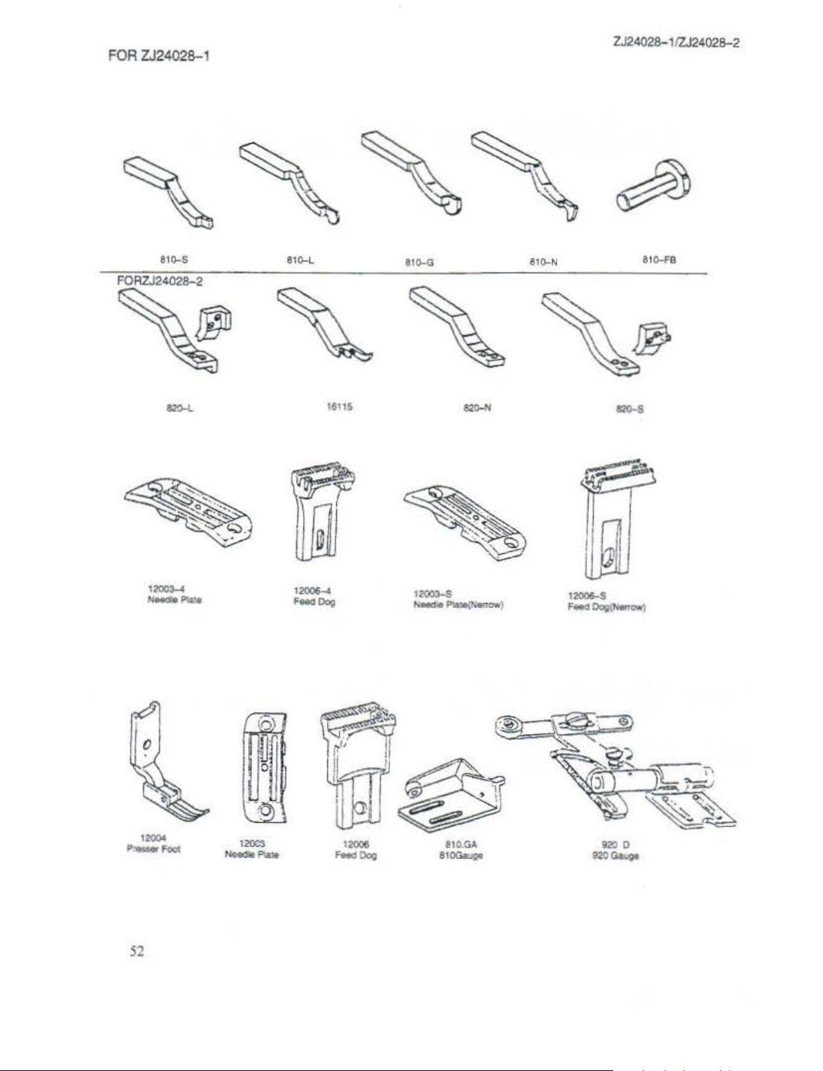
FOR
ZJ24028-1
~
~
ZJ24028-11ZJ2402B-2
~
~
81o-S
FORZJ24028-2
'
8t~L
~
1&'11$
810-G
81o-N
81
Q-FB
12005
Feocl!)og
52
810..
GA
810Gaugo
Page 54

~~~-~~~~-f}l!l
ZQ.Jili
&lE"W'W«i"
.,.,.~iji
~JlOIE.
UHU:
W.CJoel&
..
..fl""'-~
TE!;5)}£
......
CO..
L T
O.
3l'IDI(H>;>
 Loading...