

Page 1
AUTOMh
TIC
OILING
BEADING
MACHINE
• m
Jl
OPERATION MANUAL
PARTS
dllil
ZOJE
iJ.·
itt:
• m
SEWING
~JJ
=R
••
BOOK
ll
~il
~!II
iliRRR
MACHINE
ftl
J1ij
Bl E 61
CO.,
LTD.
Page 2
iY!fflibtOO
Instructions
~f4f-F*
Parts
Book
For
.. · ........ · .. · ........... · ........ · ..
1.1JL%?HI3.f4
Arm
Bed
Components
z .
..t.~
~
:J:Jfi~?Hf:l
Main
Shaft &
3.$i"M!Jffi.J'il$#
Feed
regulating
Thread
Contents
Operation
f4
Take-Up
components
···
···
···············
.. · ..... · .. · ................. · ..... · ........ · ........... · .. · .......................
Components
........... · ...............................................
······
···
................................................
··
....... · .. · .. · ........ · .. · ........... · .. · ................. · 14
...
...... ......
.........
...
......
...
...
......
...... ......
·
.............. · ..
·
· 18
2
14
16
4JIUJ~-t~
s
.ff~-1-?Hf:l
63~;f-I.?HI3.
7
.WUf:7HI3.
8jlfH.i~
9.fJL~~H4
10
..
lLfJL~~
~~?HIH4
Fabric
Piercing
Hook Drivirig Shaft
f4
Presser
Bar
Components
f4
Feed
Machanism
Components
f4
Lubrication
Oil
Reservoir & Knee
Machine
~~?HI3.#
Bobbin
Machine
Components
~t€tff.IJ!P?HIH4
Lifter
Head
Accessories
Winder & Thread
~li~
Jt!.~:7HlH4
Stand;
Table & Electric
Components
.. · ..
· ·
.. · .... · .. · .. · .. · .. · .. · ..
.. · .. · .. · .. · .. · .. · .. · .. · .. · .. · .. · .. · .. · ..
.. · .. · ..
· ·
.. · .... · .. · .. · .. · .. · .. · .. · .. · .. · .. · .. · .. · .. · .. · .. · .. · .. · .. · .. · .. · .. · .. · 26
Compcnents
.. · .. · .. · ..
Stand
· ·
.... · .. · .. · .. · ..
unit
Components ·
Appliance
.................... · .....................
· ·
..... · ........ · .............. · ........ · .. · .... · ............
· ·
..
· · ·
Components
.... · ..
· ·
....
· ·
.. · .. · .... · .. · .. · ........ · .. · ·..
· ·
.... · .. · .. · .. · ..
.. · ....
· ·
.... · .. · ........
.. · .. · .. · ..
· ·
....
..........................................
· .. ·
· ·
.. · ..
....
· · · · ·
··
..........
· ... ·
.. · .. · .. · .. · 24
· .. ·
..
· ·• ·
....
· · · · · · · · · ·
20
22
· 28
.. · .. · 30
32
34
-1-
Page 3
Instructions
For
Operation
BEFOREOPERATION
I.illtil!
~
*:bn
i1fl
~:lf'fm:rf
2.tJL~~~ll'.J-,
3.1±~-
4.li}i'JiA.
101!
l.N
ever
2.After
1:
the
counterclockwise
motor
setting
needle
down,
3.Do
not
4.Confirm
namaeplate.
.M....t.tffi7'HJ!tl~~[fl]E\I1;J~!Jt#:/J[fl],
r.J
<P,
:;r:;~-m.m:k.R.
7#JtJLtjMJ._t.P.Jft~
operate
the
up
and
turn
as
observed
use a lager
that
the
:$
l'f!ff.l)t;f§
machine
the
maching,check
the
power
from
motor
pulley
voltage
and
o
tt~'
:lf'~~{f!J~o
-t~1'1!7J!JtJL&:w!ffi
f:IT.~~
unless
its
oil
pan
the
direction
switch
ON
the
handwhee1
for
the
first
phase
(single
.iE
1i}ij
0
has
while
observing
side.)
cme
mouth.
Jr
3-phase)are
o
been
of
motor
filled
rotation.
with oil.
the
correct
to
handwheel.(The
by
check
it,
checking
turn
hand
them
the
handwheel
wheel
against
should
the
by
hand
turn
ratings
to
showm
bring
on
the
OPERATION
l.*:im
1'1!~7f3CE.JGtJL:H:iE~llt,
2.tJL~~~!Jt,
3.tJL*lllll~liUIF-=:114&:wat,
4.:f*fl:::f;\!g:7HIL~Ilt,
s.m~~~WHEil,
6./l'*.fflW~7k~il!l7*:fffl-!f.f5fiJ:J~HJ!GtJL~~i'lil
LKeep
your
2.Do
not
3.Be
sure
4.
When
5.During
vbelt,bobbin
6.Don't
clean
1.*Jlwi¥-J~~(I~l1
iJ!f0J~'f-~{$.A:f}6~;fHP~~o
~'m-ImE!Yflt7N.o
tt~/Gfti'fffW.Aa9*E.lG=¥-l~U.iZ.fffiii*W$ur_t~
hands
away from
put
your
fingers
into
to
turn
the
power
an
operation
operator,be
winder
leaves
careful
or motor or motor.Also,do
the
face
of
machine
...
~2
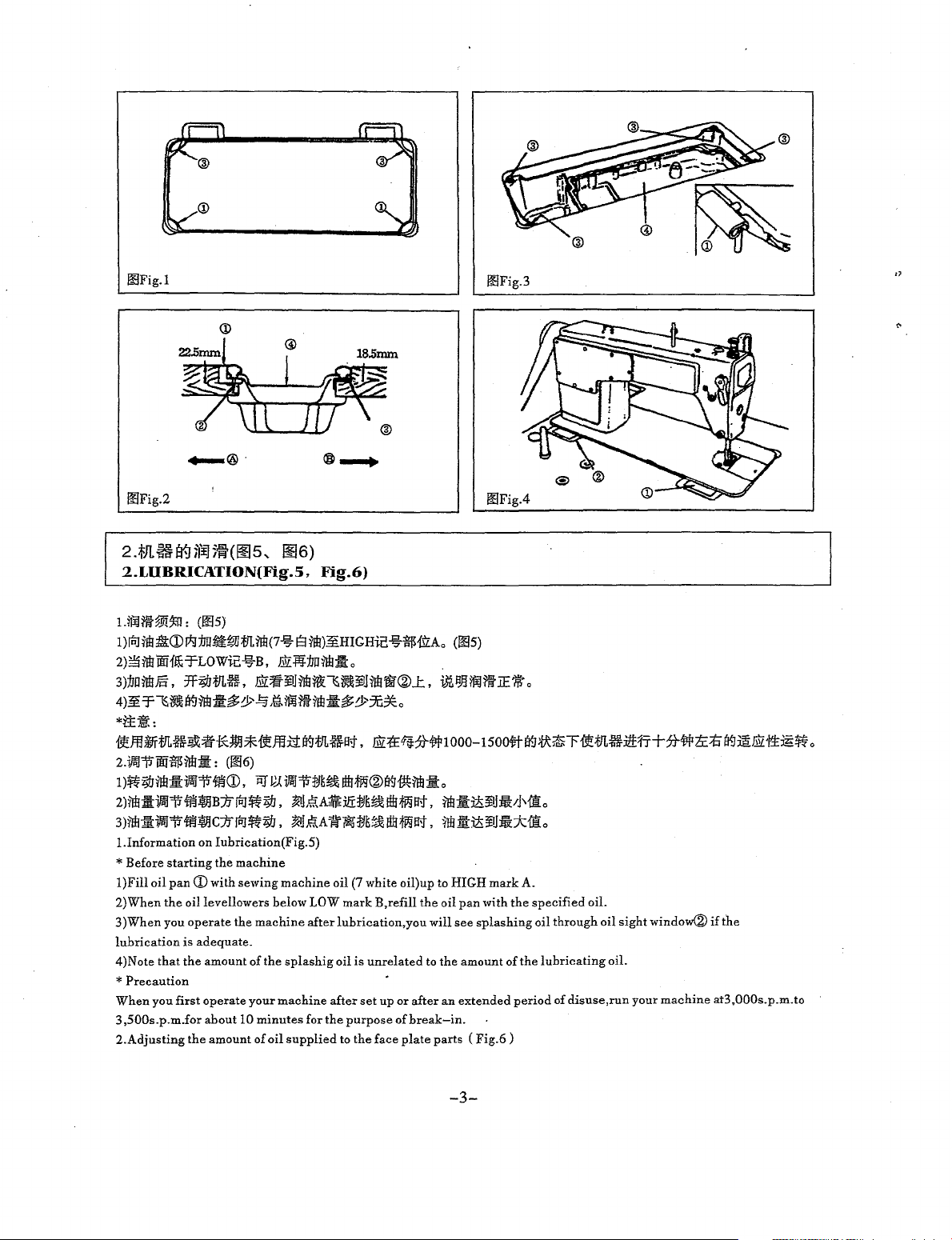
l.INSTALLATION{Fig.l,
*¥cl!fiil:3'<~:
1)
¥!llfiil:Ellm!tEI
2)
:imOO.P.Jr1.K,
l§J
JEtEB-)ft(ffl
3)
)j1J.tJL~:li:m~CD;Ii)(:.AJE:i:f1fl'Lri3,
1!14)
"
Installing
1
)The
oil
2)Fix
two
B(hinged
machine
3)Fix
side)using
hingeCDinto
head
fti:t
[!!];ft\\i!mJ§
*tWJ7JjJ:!!fiil:j:J*CD.ffl¥J:!!:&:J.i~®~JEtEA-:IiL(tllt*fl:fl:::f-)ft),
:tlL~:ii*~*.g--)ft),
the
oil
pan
pan
should
rest
on
rubber
seats
CDon
nails®.
Then
the
opening
on
cushions®on
itii.P~'f-;li)(:¥Utt-a':rFl'!l5o
-JE~-13J1lj)fJt:fJL7f3Co
o
the
needle
the
switch
from
not
to allow your
...
thread
OFF
the
machine,
head
~3
...
when you
take-up
before
with
~4)
tilting
make
or
any
n<·t
place
thinner.
turn
cover
Fig.2,
c
~)§
jfl
irll
fiil:@;/i)(:tf;¢
.!:Ji:t:t&astJL~:li:m~J*®ff!W(~,
the
four
corners
of
the
machine
side
A(
operator's
place
in
the
machine
the
four corners.(:<ig.3,Fig.4)
oil
pan@on
side
bed,
)using
the
and
PRECAUTIONS
the
power
switch
while
the
machine
the
machine
sure
other
anything
Fig.3,
nails®as
fixed
fit
the
head
to
turn
off
person's
close
Fig.4)
..t.
c (f!i 1
table
groove.
illustrated
seats.(Fig.l
machine
"V"
%&:'~if,
ON
or
while
is
operating.
or
removing
the
power.
head
or
heads
to
them.Doing
1!12)
~~tJL~~J
above.Fix
,Fig.2)
head
to
table
~~!ffi;f!li'f!~:fJLc
the
machine
the V belt.
to come
so may
close
to
be
dangerous.
is
operating.
the
hand
~WJ.Rilfl:&:J*1/J®.ffl¥i:!!fiil:J*~®
lmRt¥1
J:i9t!L~J*1/J®
two
cushion
seats®
rubber
hinge\])before
placing
wheel,
..
L
on
side
(1!13
the
-2-
Page 4
OOFig.l
®--.
00Fig.3
,,
00Fig.2
2
Jll
w
Jr.]
ifiJ5ff
(
~
5' ~ 6)
2.LIIBRICATION(Fig.5,
LW'H~~~:
I)rPJ~Il!:Cl!:CDJi;J:IJO~~tlL#l(7%
2)~ilt!ilfffl£T-LOWie!%B,
3):1Jnilt!J§.
~~T-~lY&~rmt•~~Aamrmt$~~~0
(005)
:TF~m~.
J.ili;a-i!Jrm~~lY&i!Jrm'OO"®...t.
Fig.6}
B#l)~HIGHie!%$ii'ZAo
J.ill~:IJO#l:l:o
00Fig.4
(005)
i>t~WJm.JE~
o
*i±il.:
f!ffl~tfLffB.l(;=i!f*Wl*f!ffl:lil¥1tlL~a;j,
2.1fliJi'fiii$M:I::
~~~···~·(D,~~-~--~-®1¥J~rJE·o
2)#ll\tifiil~.fMJ3B::tfrPJ~~,
3)#l:l:ifiil~if!l$1C:1J[t;]~~,
!.Information
* Before
l)Fill
2)When
3
lubrication
4)Note
*
When
3,500s.p.m.for
2.Adjusting
starting
oil
pan
the
)When
you
that
Precaution
you
first
(006)
on Iubrication(Fig.S)
the
machine
CD
with sewing
oillevellowers
operate
is
adequate.
the
amount of
operate
about
the
amount of
the
your
10
below LOW
machine
the
machine
minutes
oil
~JgA~ili:=PJ~R~Mil;f,
~h';(A1t~=PJ~~ftl!Ma;J,
machine
after
splashig
for
the
supplied
J.ili:tE&?tilf!l000-1500#"l¥J~~TiietlLff:i£1l'+?ti*ti::t:il¥JiaJ.illt!::IE~o
M:l::i!i!J!l,Nio
im:l::i!i!J~:;ktio
oil (7 white oil)
mark
lubrication,you
oil
is
unrelated
after
set
purpose
to
the
B,refill
up
or
of
face
plate
up
to
HIGH
the
oil
will
to
the
after
an
break-in.
parts ( Fig.6)
mark
pan
with
see
splashing
amount of
extended
A.
the
specified
oil through oil
the
lubricating
period
of
oil.
sight
oil.
disuse,run
window®
your
machine
if
the
at3,000s.p.m.to
-3-
Page 5
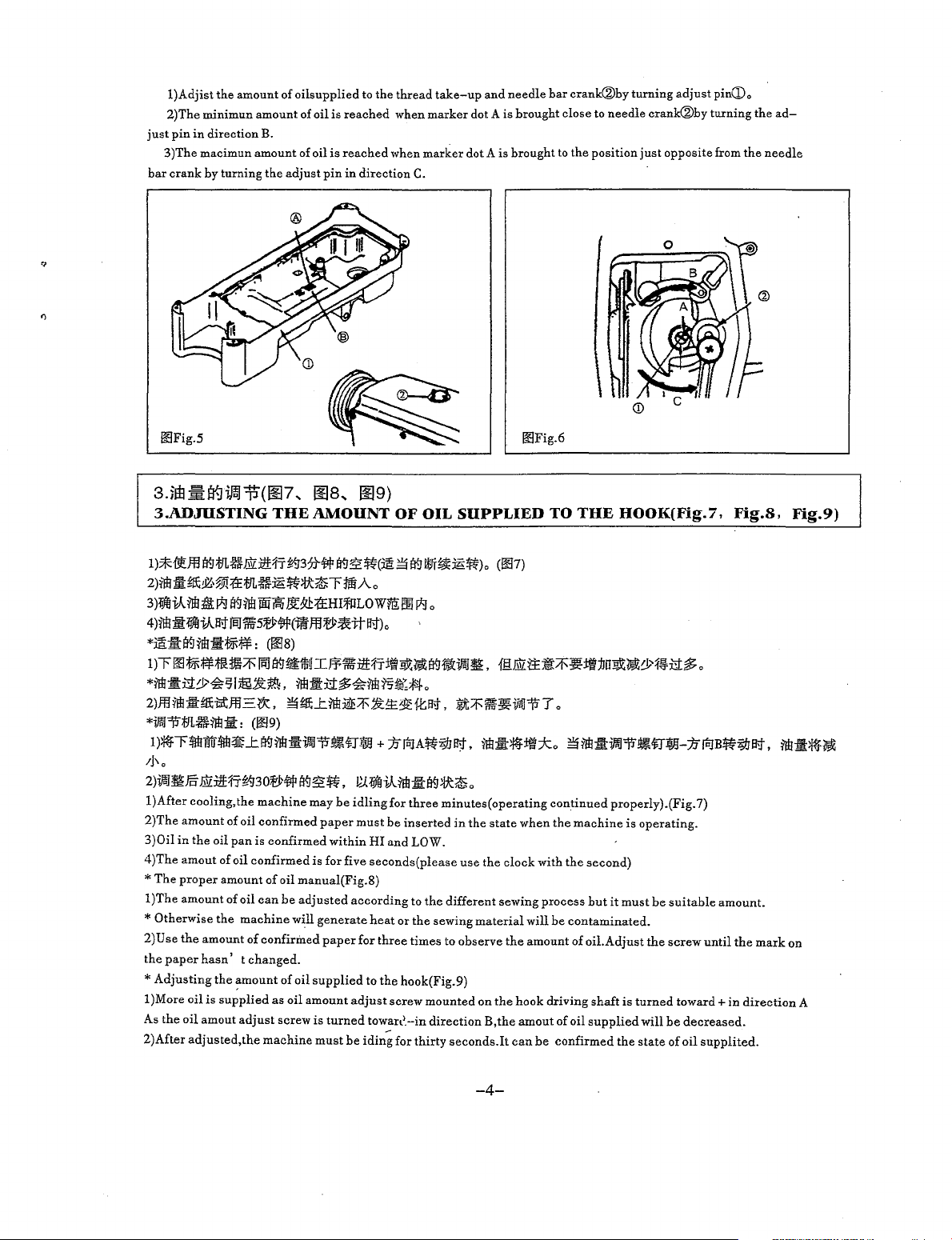
l)Adjist
2)The
just
3)The
bar
i!!Fig.5 i!!Fig.6
pin
crank
the
minimun
in
direction
macimun
by
turning
amount
amount
B.
amount
the
of
oilsupplied
of
oil
of
oil
adjust
is
is
pin
to
the
reached
reached
in
direction
thread
when
when
marker
marker
C.
take-up
dot A is
and
dot A is
needle
brought
brought
bar
crank®by
close
to
the
to
needle
position
turning
crank®by
just
adjust
opposite
pin\Do
turning
from
the
the
needle
ad-
3-fm.m~ifcJT.i(~?
3.ADffiSTING
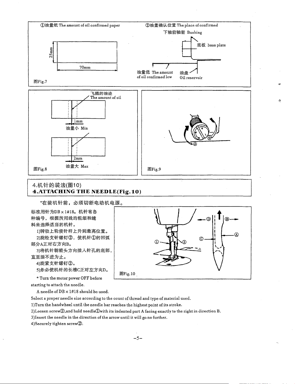
I)*fieJ13aMJL~J.llZ:ll'H7~37t#EI9:£~(:iS~Ef9J:l;ff~~~)o
2)~Jl1£~~,®!:B:m~~~tt~r:MiAo
3)lifliV.~i,l~
4)~:J:lifJiV.13;JjSJ]%'5;et#(il!f.ffl;et~tta;J)o
Ei9~Wi!11ii3t5d:13:HI~LOWV!100
*mili:EI9rwttr-¥-F
l)r00~¥-F1LHJii~lm
*~~:CI:Y~sl:®it~,
2)ff.IM:ltm;m.m.=:~.
*ifo111*1L~~:fit:
I):#fr~nfu"~~..t.EI9¥fllill:i}IJJ11~~:®J
;j\
0
2)ifoJ~}j§'
l)After
2)The
3)0il
4)The
*The
l)The
*
2)
the
*Adjusting
l)More
As
2)After
J.llZ:ltt:f'J~f.J30;et#Ef9:£~,
cooling,
the
amount
of oil
in
the
oil
pan
amout
of oil
proper
amount
amount
of oil
Otherwise
Use
paper
the
the
machine
the
amount
of
hasn' t changed.
the
~mount
oil
is
supplied
oil
amout
adjust
adjusted,the
..
~s
..
~9)
THE
AMOUNT
OF OIL
SUPPLIED
TO
THE
HOOK(Fig.7,
Fig.8,
Fig.9}
(007)
~
o
=
coos)
El9~111tl.IJ¥1%':itt1'J:Jt:W;~EI91Jlll:i!lll~,
nll~:Ct$-~~fi~~;{!:..J.o
~m;..t.~:IQE/F~~1£f.ta;J,
@.J.llZti:~~~:tl:f:JUgj(;~y:f~:Ct$-o
:tt/F\ff~iffi111T
o
(009)
+
machine
confirmed
is
confirmed
confirmed
of
oil
manual(Fig.8)
can
be
adjusted
will
confirmed
of
oil
as
oil
screw
machine
may
be
paper
within
is
for five
generate
paper
supplied
amount
is
turned
must
)Jrf;JA~~Ei't,
P..(lifJiR~:Jr~)j;IC~o
idling
for
three
must
be
inserted
HI
and
LOW.
seconds(please
according
for
adjust
be
iding
to
heat
or
the
three
times
to
the
hook(Fig.9)
screw
towan'.-in
for
the
mounted
direction
thirty
naill:~:tl:ko
minutes(operating
in
the
state
use
the
different
sewing
to
seconds.It
material
observe
on
B,the
sewing
the
when
clock
the
hook
amout
can
continued
the
with
process
will
be
amount
driving
of
be
confirmed
~~:iti!llll1~~:®J-}Jrf;JB~~a;J,
properly).(Fig.
machine
the
contaminated.
of
oil
is
second)
but
it
must
oil.Adjust
shaft
is
supplied
the
operating.
the
turned
will
state
be
suitable
screw
be
of
7)
amount.
until
toward+
decreased.
oil
supplited.
in
~:fi:#f~
the
mark
on
direction
A
-4-
Page 6
Q)M:;I:~
The
amount of oil confirmed
paper
®~i!:1if0il1fllt
The
place
of confirmed
r4lirB!i$~
Bushing
r"-i'-
Jt(;;fli
+---+--
base
plate
~[I
L
00Fig.7
00Fig.8
4.fJHt!Y-J~i!(~1
4.ATTACHING
70mm
~jj&a<JMiQE
/ The amount of oil
v
lmm
2mm
O)
THE
NEEDLE(Fig.tO)
I
.I
:1!!!:1:-fffi
of oil confirmed low
Tr-h_e_a_m_?'"1un-t--~-fi"l,:-/i-1
00Fig.9
'--......._,;;;;;;;;;;;===
Oil reservoir
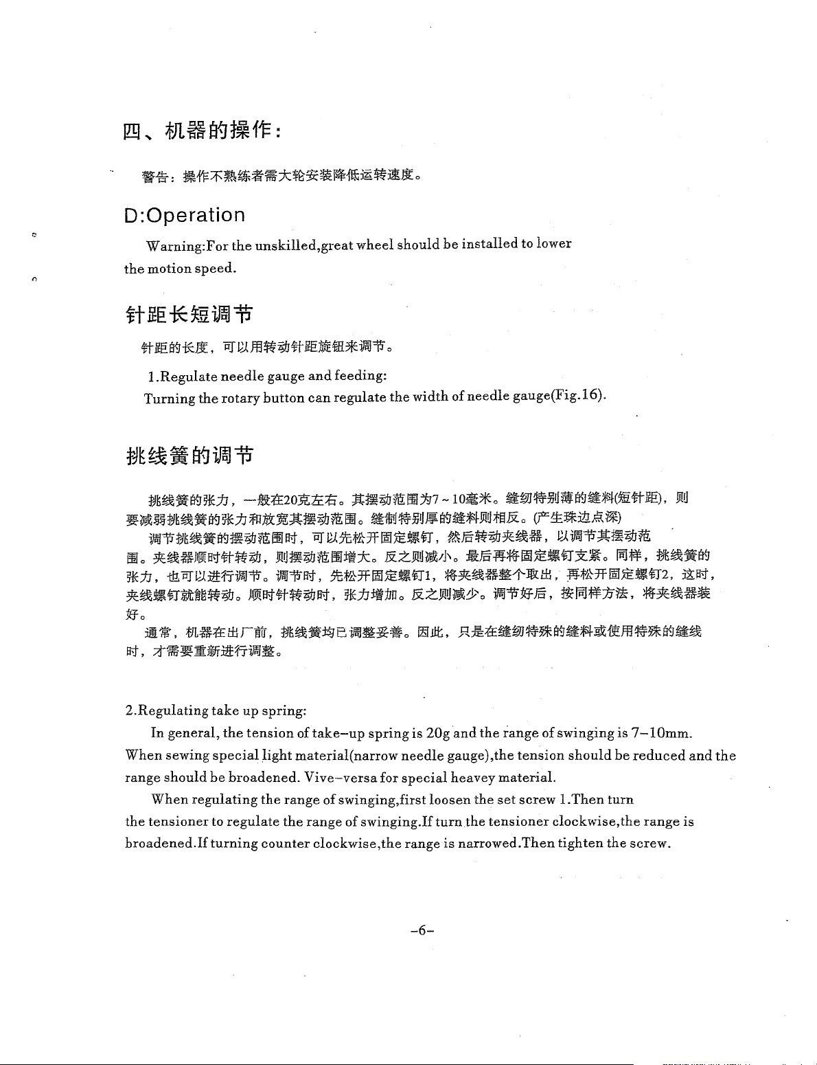
*1±
~
*Jl.
H
~W • ~,
fjf,{'fE)fj<fj-jgDB
ff~%,
Jf:-1-*z~~~
1)ff:;IJ...t~ft#iff
2):itEf'~st#"~$J®,
X
11HI;!iMffl~i¥.J;ffi£JH5fl:rt.t
~Y-.Jmtt-
~
tJJ
wr
~
i9J
*Mg
71*
o
1#18
;fJL<fj-;ff~
0
o
...t7t~J:I!i~1:\IJL
r---------------------------------------------~
{t;f!L#Q)a<JI!!JW
$?1-AJEx;j:ti:/Jrt.!Bo
3~;f!L#GC~:/Jrt.JMA#~i¥.J~$,
][~M:If':itf::;fg
4)1iJE~)t<fj-~$J®o
5)%-!Z,ft;f!L#"a<J*;flcJEx>ttc:/Jrt.IDo
*Turn
starting
A
needle
Select a proper
l)Turn
2)Loosen
3)Insert
4)Securely
ll::c
the
motor
to
attach
of
DB
the
handwheel
screw®,and
the
needle
tighten
power
the
x
1#18
needle
in
screw®.
OFF
needle.
should
size
until
hold
the
direction
before
be
used.
according
the
needle<Dwith
needle
of
to
bar
the
the
reaches
its
arrow
00Fig.10.
count
of
indented
until
thread
the
it
and
type
highest
point
part A facing
will go
no
further.
-5-
of
material
of
its
exactly
stroke.
to
the
used.
right
in
direction
@
B.
Page 7
D:Operation
W
arning:F
the
I)
motion
or
speed.
the
unskilled,
great
wheel
should
be
installed
to
lower
l.Regulate
Turning
:f!J~~~i¥J5iUJ,
~~~U~:f!J~~~I¥J~iJ;f!JJ1Jc~;tt:~?ijjm;~~Jo
•~•~•I¥J•?ijjm:~~J~.~~~-*~~•n.•~•?ijj~~•.
Ill
o
~~@JIIDiB'.t#ff?ijj,
5!EJJ,
ill~~:llHJ--~
~~•n8.Jt~~ff?ijjo
the
needle
rotary
gauge
and
feeding:
button
-~:t£2o3'ltc:E
o
)I!IIif:!;j"#ff?ijj~,
can
regulate
o
Ji!tl~Z9Jm;
lft.J~Bt,
Effi:lt:ko
~tt-*~k:-ni,
~j]:ft:flDo
the
width
;!t~~MiHID]'g7
~1liiJ~JiUJ¥E!~~t-I-Ji!U;fEJ&o
&zJi!tl~/j\
&zJi!tl~&o
of
-Io~*o
o
*~~-~~llJU£,
needle
gauge(Fig.16).
~WJ~jjUiii¥J~;f;J.(m#lf.E),
(F1:~:Itl;~~1*)
Ji!tl
~-~;!t•?ijj~
li~W*~k:·n~~
JffiJ~M-~,
~~¥-¥1Jrt,
o
iiiJ;f-F,
:f:JK~iti¥1
Wtt-*~k:-n2,
J!B-f,
*~~-~
"!Efo
••.
at,
2.Regulating
When
range
the
broadened.If
mB:tEilirfi.m~W~B··~-o~~.R~:tE~W~Ri¥J~#~~ffl~R~~~
~$~~J~JTJlt171J;iJ.o
take
up
spring:
In
general,
sewing
should
When
tensioner
the
tension
special
be
broadened.
regulating
to
regulate
turning
of
light
material(
the
range
the
counter
take-up
Vive-versa
of
range
clockwise,the
spring
narrow
swinging,first
of
swinging.If
for
is
20g
needle
special
loosen
turn
range
and
the
range
gauge),the
heavey
is
material.
the
set
the
tensioner
narrowed.Then
of
tension
screw
clockwise,
swinging
should
l.Then
tighten
the
is
7-lOmm.
be
turn
the
screw.
reduced
range
and
is
the
-6-
Page 8
When
sioner.
crease
regulating
Then
loosen
tension.
the
set
Turning
tension
screw
counter
of
take
2,so
the
clockwise
up
spring,first
tension
can
serew
reduce
loosen
can
be
tension.
set
screw
turned.
1,
Turning
and
tade
clockwise
out
the
can
tenin-
ff)jijl~ffh.····~~~&~~-·o·W~M~.~~*ff)jijl~ffhc~~.ey~-m~
JJHf~~-ff!P,It]',
Jftilff!Pltr'
ff}jijl~ffh,~~-~-·*·~~&,~~-~@-®o
~~7(J¥)JYfffi"ftf~:/J(riJ~?ijjo
~~;j\l:[)jijl~ffh
0
,OCZ,
·~*-!-~,
ey~002l(~)JYf7F~jjiPJ,
~;fj
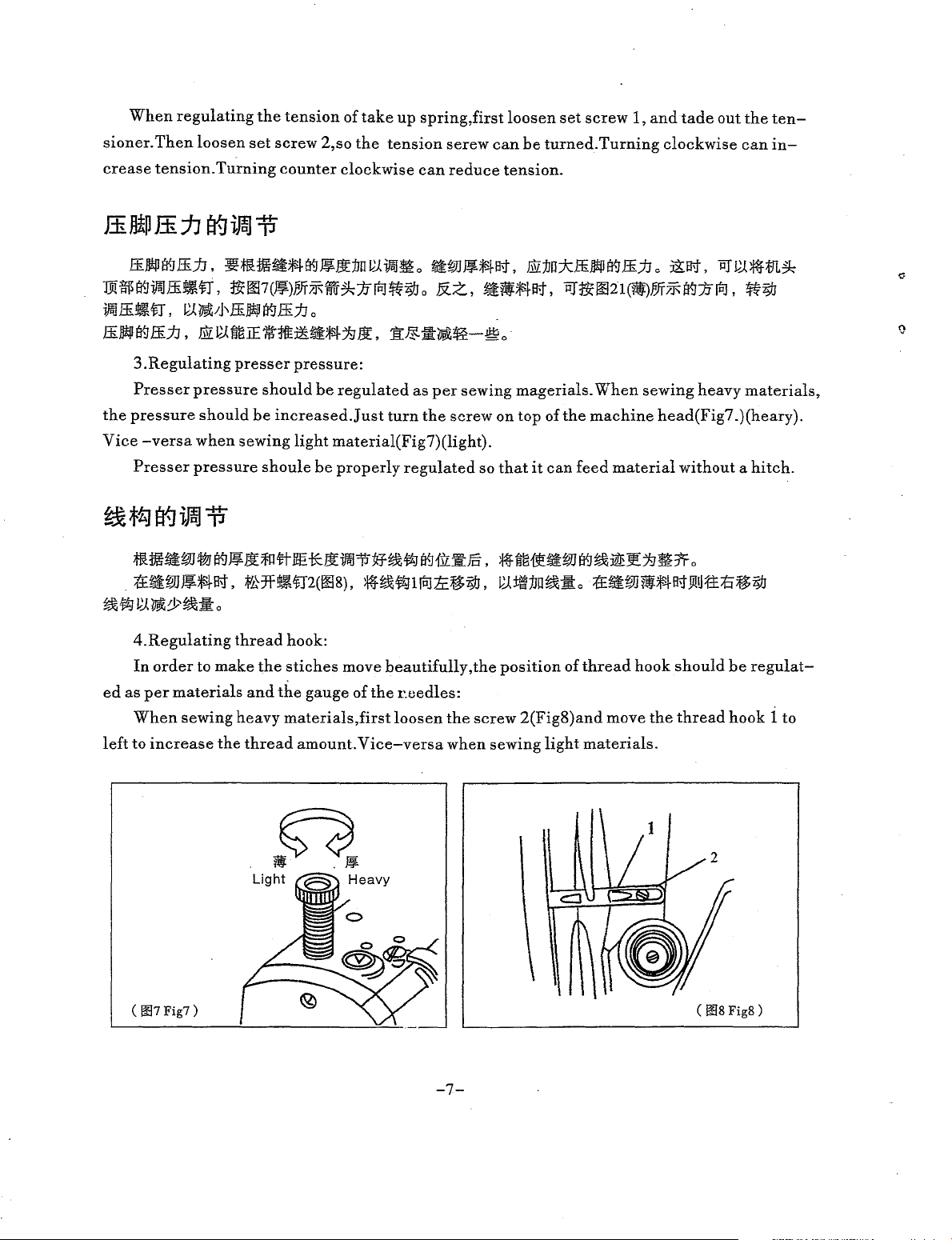
3.Regulating
Presser
the
pressure
Vice
-versa
Presser
presser
pressure
should
when
sewing
pressure
pressure:
should
be
be
increased.Just
light
shoule
be
regulated
turn
as
per
the
sewing
screw
material(Fig7)(light).
properly
regulated
so
magerials.
on
top
that
it
of
can
the
feed
When
sewing
machine
material
heavy
head(Fig7.)(heary).
without a hitch.
•••w•~~&®~m*&Jftil$~-~~~-~.••~•w~••E~•*o
.
;frti:WJ¥~-1-a-f,
:f'kfft~fi"2(~8),
.Mt¢;JlfriJ:le~;tJ,
~~:JJO
••
c
:tEatm~~~Ji!Uf:l:i(:i~;tJ
-~~~Y-·o
4.Regulating
In
order
ed
as
per
When
left
to
increase
materials
sewing
to
thread
make
heavy
the
the
and
the
thread
hook:
stiches
move
gauge
materials
amount.
beautifully
of
the
r.eedles:
,first
loosen
Vice-versa
,the
the
screw
when
position
2(Fig8)and
sewing
of
light
thread
hook
move
materials.
the
should
thread
be
hook
materials,
regulat-
1 to
(
007
Fig7)
-7-
(
008
Fig&)
Page 9
3i
..
*Jl
~+
Et-.1
~
*
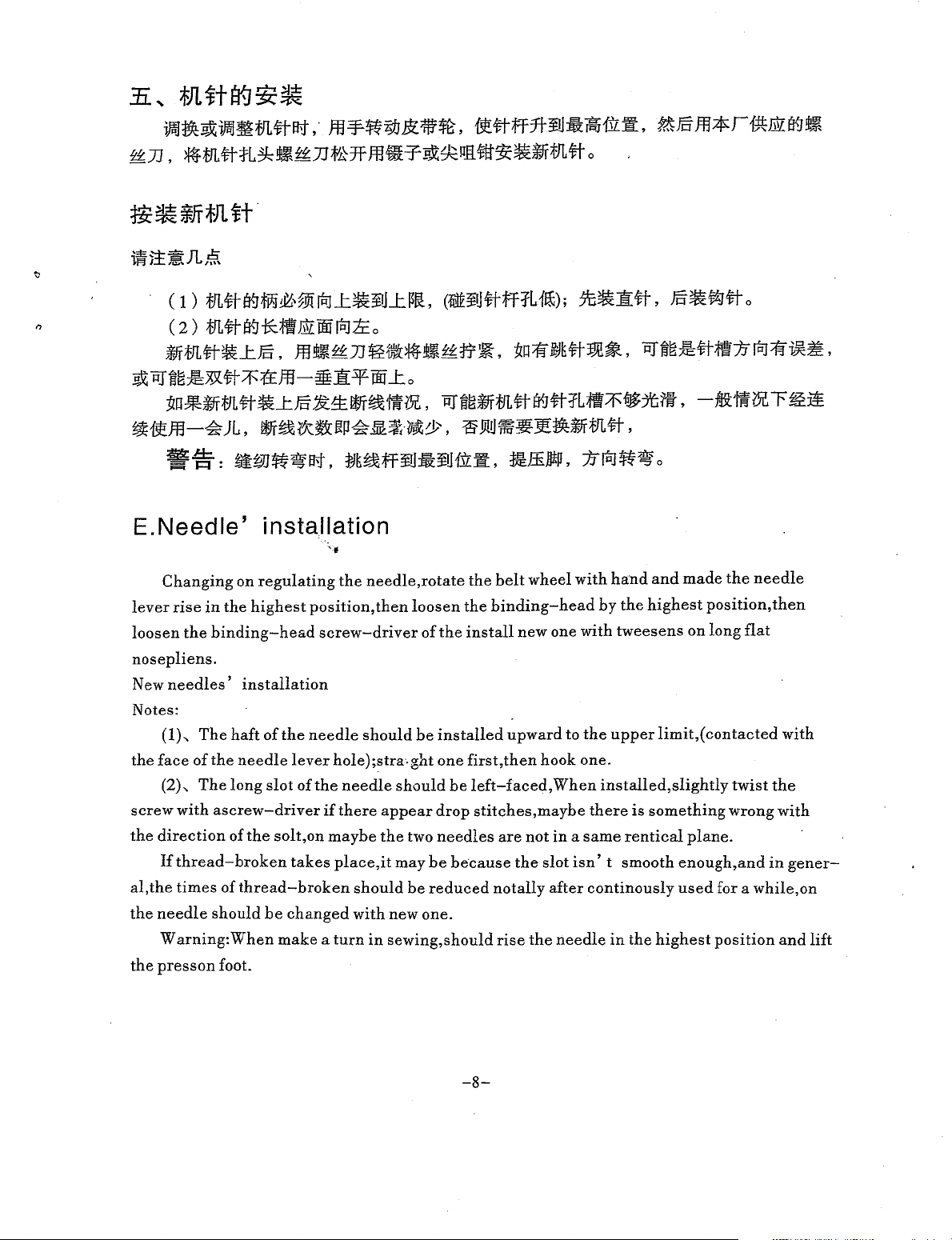
••~••m#~.·m~~~~-~.~#ff~~••&•.~mm*r~~~•
~n.~m#~~•~n•Hm•~~~~w~•~m#o
C
1)
m*tBfW&,@lrtJl:.~Jl:~li.
C
2)
m#i¥.J-K;ftbtrOOrtltco
(1Pl~J#ffiL1!£);
J'G-1!#,
Ja.#T#
o
~m#•l:£,.m&~n@•~•~~-.~~-#~•.~•~#;ft~rtJ~~~.
~~~~~.5P(#7f'{±}tJ-~1[fTiifl:o
~-~m#.l:£~~~--~.~-~m#i¥.J#R;ft7!'$~M.-&M~~~~
~~ffl-~JL,
Wf~ik~JJ!P~~~·?J~d.>,
~Ji.!Um:~J!·lffm#,
-~:
E.Needle'
Changing
lever
rise
in
the
loosen
nosepliens.
New
Notes:
the
screw
the
al,the
the
the
the
binding-head
needles'
(1),
The
haft
face
of
the
(2)-.
The
long
with
ascrew-driver
direction
If
thread-broken
times
needle
Warning:
presson
of
of
should
When
foot.
~W~~~,
~~-ff¥U-~H.il:•,
installation
'f
on
regulating
highest
installation
of
the
needle
slot
the
solt,on
thread-broken
be
changed
make a turn
the
position,
screw-driver
needle
lever
hole);stra.ght
of
the
needle
if
there
maybe
takes
place,it
should
with
needle,rotate
then
loosen
of
the
should
be
installed
one
should
appear
the
in
sewing,should
two
may
be
new
drop
needles
be
reduced
one.
:r£ffiJW,
the
belt
the
binding-head
install
first,
be
because
new
upward
then
left-faced,
stitches,maybe
are
the
no
tally
rise
wheel
one
hook
When
not
in a same
slot
after
the
needle
to
~rtl~~
with
by
with
the
one.
installed,slightly
there
isn' t smooth
continously
o
hand
and
the
highest
tweesens
upper
limit,(
is
something
rentical
in
the
highest
made
on
plane.
enough,
used
the
needle
position,
long
flat
contacted
twist
wrong
and
for a
while,
position
then
with
the
with
in
gener-
and
on
lift
-8-
Page 10
*ll
~t
~ll
~~
gg]
Eli~~
Jl:t;f]L~:tftfj
~%
16#
rat~~J¥j;f}L~~DB
'
~
tm~
40/2-40/3
-~
~~
60-80/2
ji:llf_t7BJ
18#
20#
~illtl~=
r!±l
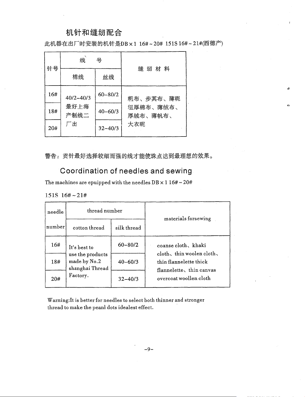
Coordination of
The
machines
are
40-60/3
32-40/31
epuipped
needles
with
xI
I6#-
20#
ISIS
m
~JJ
:fi
JlSl.
;Efi{!J"
~ll~;tm{tl
~fJX;f!J
t/7;lt{tl"
'\
ti~1!J
'\
ti
rjiJL
{tJ
jc;;&!W.
and sewing
the
needles
DB x
116#-
I6#-
1iP~
'\
'\
20#
21#([91,~~)
151S
needle
number
16#
18#
20#
W
arning:It
thread
16#-21#
cotton
It's
best
use
the
made
shanghai
Factory.
is
better
to make
thread
thread
to
products
by No.2
Thread
for
the
peanl
number
silk
60-80/2
40-60/3
32-40/3
needles
dots
idealest
·-
thread
to
select
both
effect.
materials
coanse
cloth._
thin
flannelette._
overcoat
thinner
cloth._
thin
flannelette
woollen
and
forsewing
khaki
woolen
thick
thin
canvas
cloth
stronger
cloth,
-9-
Page 11
2.
PI
§~tc
~
1¥.1
~
l."Mc$Jt?R
5.
4.
#JdE;r\
:f::t]~~iE
~
_t
1r
w~
ff
7.
CD~~f&ZfBJ1f:&<~~fffME1tl!
~~~~if&B3fFffl(2)~<ftfilif~IE
~
s.CD#ffietl&if~IE1ijij,~#I¥.Jft:
tt~JrtnJ
~Ilirtt-9Cm£II!®mtt-~%~tt-%/f-
m@~tr/f-1£1PJ--t-~1I¥W...t®-
~#1Ctl~iE1iif!@#fff0~#1C:ti
~
iE1ffrlCV~~~:l:15£,~if:liff.:fJ-:k:
~xtC2>trL#I¥.J~i'iffii~;JW=ff!S
1ifl-tnJ1C"11J5E
I2Sl
6.
CDm7f~~vr.t~~:Yc~fngf£t
(2)iflil
9.
CDf:l:~#ffie:tl~:e1Jl.~C2>tt~
~#~~~x1fiH#®~~.OC:l:15£
1I#fnlie~~~a:~~#[O]ii."11Jd>
:t:J;x:DFliltnJtv£,
~Yf\111~~&~#
3.Yi~~H1!!Jr~
~~#{ill[
0
1Itt-~>tf'1E~tt-
c
&~
#
r
&~
ff
li.#Jff
Jlf.J§
12.fJL#
~
lO.CDlB:JfifliJ~#ff1Ctl®£~~m
#®:®ffl~ms1rf1L#~%@~
jfiflij~{t{E
~#
f{{J1Ct!JrfnJ
ff£?
~#~ie~
tl:tr
tr
1I#IPJ~#;Gfa]JEE~0.20~*·~j>
Wi-1I#M
&t#®~#ic:;fi:fl
Q)iff:fl5l:5&'11:§~~
:itf:r::::r;fif~$&~£'£0
IPJ-~~:.f-
@#ff~1!£:ff
~#:ff
J:f{{J1i#ilP~:JLfnJJ:,
3 - 4
~
~m?
,1l.3HiJJU~#gc{~
~~H?tt-;t&
Tiff
~*CV!P#:tlfie
fPJt~fi?
£"£*1-M:Jt~y;;{jl,
tt-:m:
_t
@~~
filJ;f,.j
tnJ
ti:ti~tc
Jl~~
13.CD#%~~%~.xt®rrJL~*i~
tJL#
M:i::*~®~~t~:i:~~@3f:
~~~fOOO~:*~®~~:fflill.:fJ@
~*:1:1:~
~:tft#~¥1Jief¥
#Z.fBJNEt*f5-6~*
tr~t~i'l?~~~~~ft~-Ej:ft#
q:.Jr..'at~#gc~*¥IJ~trzfBJNE~
1.5-l.s~*®fl-;ff
1PJtjf'1£?
¥IJtt-~IWi4-5~*0
®&~$=0!,:12t~~#~$"1JJ'
a'.tfa.J:lt
#1i1Jl.W,3f-&Bjjlg!0.5-l~*o
14.CD£~m~~~®£~Jrm#®
~ffll!ltl:!€it%-~~~@JE1ifij3f:~~
1ftiltkoo~®1ftil~~~m~®ttZ)}J~
~
~#ff¥Irf
lf!..®~~-¥~~#~~
JL~M:tft<ft~~H
®"1JJ#IWJB:ff
~r~fl-zfBJ:ff
ll::B
~#~*
3f-&
,:iii!U
15.J$T#
fftl#
I6.CD:fJL#~%
ll®~Jri~:ltW@~t~ff~¥1J!i~
11Iifa-JJ.l9t~~®J:i~~;fif
WT#
I.A.1*f'F::F~t~
~xif®...t
r:t!Ht!.~x>t
rr
IfF~
-10-
17.CD£~m#®...t
®~9Mt~.OC@1:Jt~ff¥IJ!i~f.1l~at
::t~~®~
rr~%;ff~M~ris-2o%
r:f!JJtJ.B:~xifi1E
JiFJ.~ZfJJE[w~®fflm
Page 12

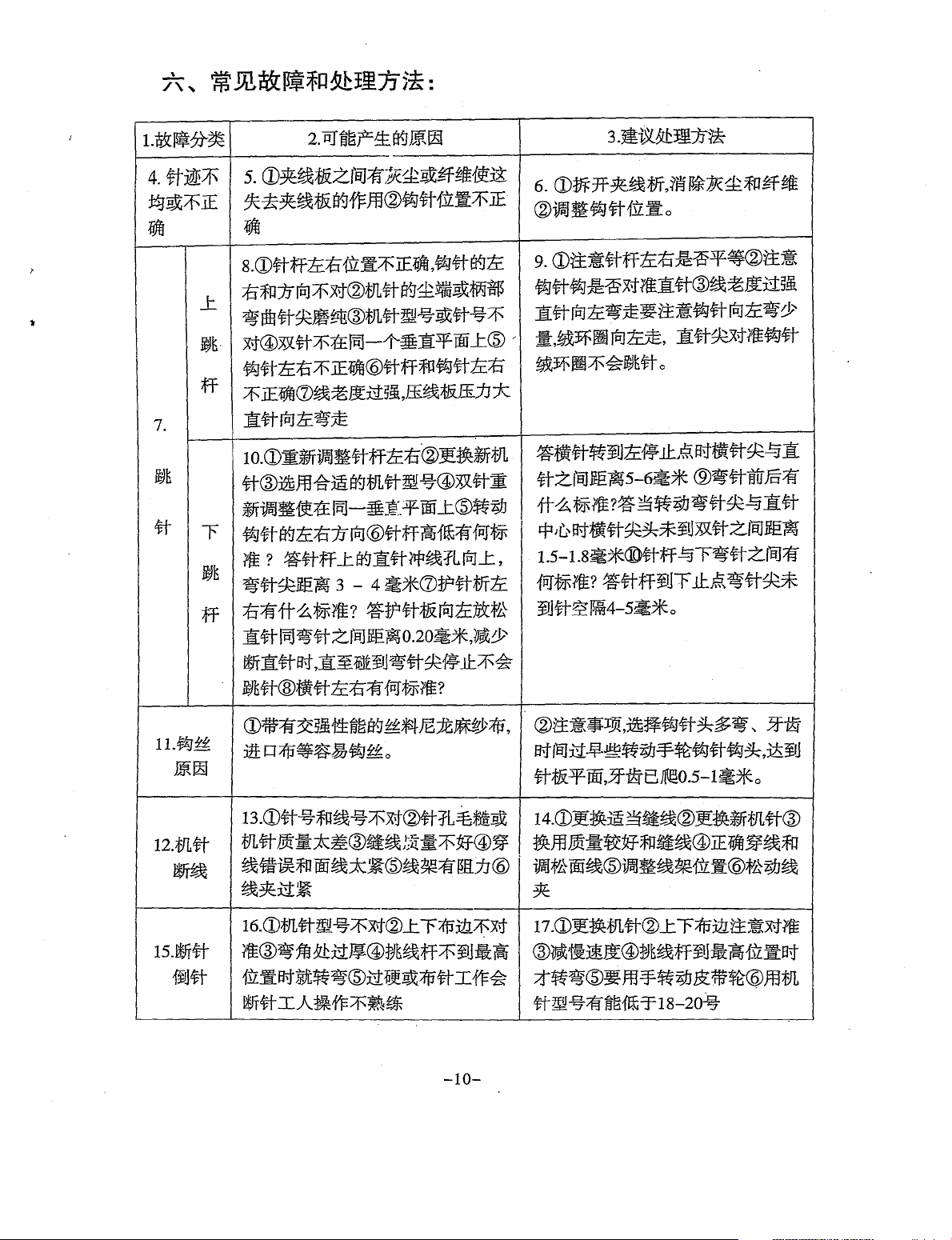
/'\--. Usually malfuction and how to deal with
1.Malfaltion assort
2. The possble reason come into being.
3
.Advise
how
to
dead
with
4.The needle trace not well-distributed or incorrect
5. (1).Between thread board have ash or fibre let this losing
(2).The position of the hook needle incorrect
6. (l)Open the thread· board elin'.inate ash and fibre.
(2).Reguiat the position of the hook needle.
7--.
Drop stitches : upper ones
lower ones
8--.
(1).the position of the needle and its lever
and
the direction of
are all incorrect.
(2).the point of the needle is blunt and bended,and its haft as well.
(3).The type or the number of the needle is incorrect.
the
't
needle
(4).The
two
needles are not in a same vertical plane.
(5).The position of the hook needles are incorrect.
(6).Something wrong with the attched needle plate.
(?).Something wrong
9
...
(1).Regulate the position of the needle lever again.
with bith the honizoual and bend needles.
(2).Change a new needle.
(3).Select the correct tybe of the needle.
( 4).Adjust the
(5).Move the hook needle towards left
(6).Make adjustment of the screw
two
needles in a same vertical plane.
and
in
the attached needle plate.
right direction.
(7).Make adjustment of the working hours of both the honizaual and bend
needles.
10-..
Phread-broken
11--.
(1
).
The number of the needle is inconsistent with the number of the thread.
with the needle.
(2).The hole of the needle is rather crude on the quality of the needle is too poor.
(3)The thread is of
(4).Make wrong thread and the ball thread is
bad
quality.
too
tight.
(5).There is assistance with the thread-stand.
(6).The thread clamp is over tight.
-11-
Page 13

12., (1).Change suitable thread.
(2).Change new needles .
. (3).Change better quality thread.
M
thread
tPl
(4).Make
(5).Begulate the thread-f.teand.
(6).loosen the thread claimp.
13., (1).Needle-broken and needle-returned appear.
14., (l).Wrong thpe of the needle is used.
(2).The upper edge of cloth is not aligned with the lower one.
(3).The turn corner is
(4).The needle thrns when it isn't in its highest position.
( 5). The cloth
15., (l).Change the needle.
(2).Pay attention
(3).Lower the speed.
(4).Don't make the needle turn until it is in its highest.
(5).Move the belt wheel
l$
m
~
Easy-worn
correct and loosen the bali thread.
too
thick.
is
too hard.
to
the alignment with the upper and lower edge of cloth.
wi~h
hand.
E!ic
14
attachments:
0 0
T~-if
T:m-if Lower
Lower
#f&
needle
bend
needle
honizoual
plate
needle
1!:-if
~#
-12-
straight
hook
needle
needle
;f-[;!f tooth
ff.Hf!J
press
en
©
foot
Page 14

Figure
controling
of
regulating
the
position
left-deviation,rignt-deviation
of
upper
jumper
thread
pin
screw
and
left-devia6on
-$-~~--
wrong
pm
screw
~~=m*~~.~mx•~n~~.
W
arning:Don't
-driven
screw
for
regulating
in
order
revolve
not
to
lower
the
pin
make
jumper
screw
it
broken.
thread
~~m~•~
with
big
~*
bend
straight
.!Eiii
right
screw
needle
needle
ffi
,ight-deviation
11#
straight
needle
wrong
r~~#1ir:il~
figure
of
position
of
bend
-13-
needle
in
lower
hook
thread
needle
Page 15

.
..,
Model
(For
Medium
Heavy
Materials)
-14-
Page 16

46
-15-
Page 17

Arm
{tf%
Bed
Part
I.tJL7e?tm
!¥%
Ref. No
itt=
I OI.Ol.l-0
2 01.01.2-0(229-45356)
3 01.01.2-1(229-21308)
4 01.01.2-2(229-21407)
5 01.01.2-3(229-21704)
6 0.1.01.2-4(229-21803)
7 01.01.2-5(229-21506)
8 01.01.2-6(229-21209)
9 01.01.2-7(229-21605)
10
01.01.2-8(229-45307
11
01.01.2-9(SS-8090670-SP)
12 01.01.3(B3188-552-EOO)
13
01.01.4(229-00757)
14 01.01.4-1
01.01.4-2
15
01.01.5(SS-608041 0-SP)
16
01.01.6(229-00609)
17
01.01.7(SS-412615-SP)
18
01.01.8(229-00401)
19
01.01.9(SS-412915-SP)
20
01.01.10(110-00619)
21
Ol.Ol.ll(TA-2000502-RO)
22
01.01.12(TA-2101002-RO)
23
01.01.13(SS-8150710-SP)
24
01.01.14-0(229-32552)
25
26 01.01.14-1(229-32503)
27 01.01.14-2(229-32602)
28 01.01.14-3(229-32701)
29
01.01.14-4(SD-0380552-SL)
30 01.01.15(TA-1250705-RO)
31
01.01.16(229-20706)
32
01.0 1.17(229-02159)
33
01.01.18(229-02209)
34 0 1.01.19(229-20607)
35
01.0 1.20(229-20508)
36
01.01.21(110-01500)
37
OLOL22(TA-1250406-RO)
38
01.01.23-0(229-01250)
39
01.01.23-1(229-01201)
40
01.01.23-2(229-01300)
41
01.01.23-3(SS-6060210-SP)
42
01.01.24(110-28008)
43
01.01.25(SS-6060210-SP)
44
01.01.26(229-0 1003)
45
01.01.27(TA-0850604-RO)
46
01.01.28
47
01.01.29
48
49
Ol.OL30(II0-04109)
50
01.0 1.31(229-02605)
51
01.01.32(SS-7II0540-SP)
Components
No
tJL%'li'Mtf:························ Arm bed
~~~~IHtf:·
~~-iij:·······
~~i!ifj
~~--
tk~;fti·······"'""'""''"'"'Thread
~~;J:&
~~-~
~~~-·
:fi~~J{i)iif'lJ~·--··········--·--Thread
~~~~-~
tk~~···
~~~~m_{tf:
;~'if~~~
~~
..............................
~W~~~-11-·----·········Screw
jl}~~fHF
:fi~~:tftp
-IY!tl'OO;fiii·
iY!tlW;f&·~·····
fJ!tlOO;f&m·······--········------·Gasket····
ff'J!E~3t*JL£--
:J2i;f~ff'J!E'im1J=i'L£--·
~~~-~
W~:l:t~~m_{tf:·
00'~:11~11
/j\~~;f&·····--·······--···--···Thread
/j\~~-·
/j\~~-11
#':tf!l!!;jpj
.:=.:B~:l:t~.zg
W1lV.
· · · · · · · · · · · · · · · · · · · · · · ·
WKt§
......................
llif;f&-':3<~-zg
;t:J~.zg
.....
~.zg--~
W;f&iJil'f'\J'=i'L£·
11E1Iim1tf:·········
1tE1Ji
....
· ...... · .................. Slide plate
tfE1fi1li(·
........
1fE1fiilt·~
#'1Ji"""
#'1Ji-~
Jli;1Ji·~·
:fi~~a:tfi1HL.£
W1Ji~1:1'!i1Ji
m.!%.Jll!!···
~%.Jll1!················
.:E!)!IJ~
......
a*1fi
...........................
a*•~·····
Description
assembly-································!
· ·· · · · · ·
·· · ······
..
.................
i9J;f&
.............. · ....
...
· ·
·.
· · · · · • · · · · ·
·Tension Complete subassembly·
Thread tension nut···--··--
--Thread disc rotation stopper
········Thread
tension
spring·····························
release disc·
........................... Thread tension disc
........................
·
..
· · ·
..
· ·
.......
...........
........................
.................
...... ·
.. · .. ··
,a··
..
··
.. · ..
~-~
........ · ....
..........................
................
...........
.....................
.. ·
..........
·
....................
· · · · · · · · · · · · · · ·
..
· · · · · · ·
..
..
:j'L£--
..
" ·
.. · .. · .. · .. ·
Tension sorew
···· ....
·Take-up spring · ·· · · · · · ·
·--·--·Set
screw··········
Tension release pin
·Oil packing subassembly
....................................
tension post socket
...... ·Oil packing cover ·
oil
wick
..........................................
................................................
···
.. · ..
--Thread take-up lever cover-
--Thread
take-up
Face plate asm
Screw
................................................
--Rubber plug
.........
Rubber plug
Thread tension
·Face plate thread retaining guide subassmbly--·I
Face plate thread guide retaining
········Thread
···
......
·Thread tension screw--··
......
·:Rubber plug needle drining crank hole ·
.........
Three hole thread eyeket·
·······Face
plate · · · · · · · · · · · · · · · · · · · · · · · · · · · · · · · · · · · · · · · · · ·1
----Face plte sealing gasket
lever cover screw .. ·
....................................
..... · .............................
......................................
......................................
screw"""""'"""'""""""1
tension
disc··--··--·····--·
tension spring"
..................... Face plate thread guide
· · · · · · · .. ·
..... · ..
........................
· .. ·
......
...............
· · .. " .. · .. · · .. ·
.....................
·"
"·
"·
.... · ....
............. ·
· · · · ·
'·
· · · · · · ·
...............
....
···
"··Thread
·······Rubber
..
"·"·Throat
·· ..
"Throat plate screw
.. · ..
·Bed screw stud
guide right·
Thread guide screw
plug"·
...
·····
Bed slide subassembly·······
.... · .. · ..
Silde plate
Slide plate spring screw
Rubher plug thread take-up lever link pin hole 2
spring"·
plate · .. ·
.. ··
.... · ........ · ......
........... · ...................
......
........................
............ : .................
............................
.................................
........... · .... · ............ · ..
..
... · ..
..
··-······"····
....
· .. · .. · .. ·
.........
...........................
········
......
........................
....................
..
· · · · · · .. · ·
........................
........................
..
··················
.................
·········"············
.. · ....
··
.....
...... · .......... · ........
...........................
...........................
···········
······
... · ..
..
.. · ......
.......................
.. · ..................
··
....
··
........ · ......
· .. ·
.. · ....
..........................................................................
........................ Brandplate··
..
.'
· · .... · .. · .. · .... · .. ·Main shaft bushing
..
........ Brand plate rivet··
Connectingrod
·········
..
······Screw
..
·····
.................................
..
··········-······
..................
....................................
................................................
..
· · ·
Amt.Req
"·········
··
······1
..
· · · · · · · ·
..
····
...... · ....
·· ·----··1
...............
··
....
······
.......
·········
··············2
··
.........
...... · ....
·····
..
····.·
·············2
.......... · ·1
~:I:
1
1
· 1
·1
2
I
· · ·1
!
···I
I
1
1
--·1
}
..
·I
· 1
1
8
·1
· 1
1
2
..
·I
1
· 1
1
1
!
1
·1
!
·1
·2
1
2
··
2
4
·I
l
I
2
-16-
Page 18

34
-17-
Page 19

Main
Shaft
Thread
Take-up
Components
i'F%
{tj:%
Part
Ref.
No
01.02.1-0(110-39070)
2 0 1.02.2(229-031 08)
01.02.3(55-8681650-TP)
3
4 OL02.4(SS-7681650-TP)
5
01.02.5(R0-0442401-00)
01.02.6(110-39062)
6
7 01.02.7(229-27206)
8
01.02.8(55-8151550-SP)
0 1.02.9(229-03504)
9
01.02.1 0(229-03405)
10
01.02.11
11
01.02.12
12
01.02.13
I3
14 01.02.14
I5
0 1.02.15(SS-866061 0-TP)
I6
01.02.16(229-04155)
0 1.02.17(229-03306)
17
18
0 L
02.18(SS-815II50-SP)
19
01.02.19(229-I9559)
20 01.02.20(CQ-3500000-FO)
21
OL02.2l(B
0 1.02.22-0(11
22
23
01.02.23(B1408-552-000)
24
0 1.02.24(b1905-541-BOO)
OL02.25(B
25
01.02.26-0
26
27
01.02.26-1(229-03900)
28 0
1.02.26-2(229-04007)
29
01.02.26-3(R0-0291801-00)
1903-552-000)
0-05204)
1212-552-000)
30 01.02.27(229-03702)
31
0 1.02.28(229-03207)
0 1.02.29(229-03009)
32
33
j
01.02.3I
No
~~AAffffl.
<ft;jfa!J~
#;jfa!J;JW~I§l~~
<ft;jfa!J';JW)Effl~~
~Ul-~O~fm
~~AA~ff
_t~
_t~~fi"
..t~lrrlfiit
..t~Fo~~g_llftj:
:lli4\J6!ffi-········· ······
JZ'.1tf6~~~
~fJZ_t1f~·-·
fit
_t~~fm~~
_t~~~
_t~
fi~AA:Jiff~~~
fi~AA~ffil\j
fi~AA~ff~rmAA
:t:JkAAa!J;JWii::afE~~
ti~AAa!J;JWffl.
<ft;jf~;jf
<ft;jf~ffi.
<ft;jfa!J;jWtp;fli
¥1!!itiJllfl'~ffl.{tj:
B:IJ;JW¥1!!itWJl'~
B:!J·~$:ftiJll!T.f~~
O~iWrmi&'itlll···
..t~$fg
..t~iltr~~gll.
_t~
_t~~Yffii-~
ftj:
·········
···
······
···
···
···
···
···
············
······
···
··· ···
···
··· ··· ···
······ ··· ......... Indented fork
3.f~;jf~
1m·-
...... ·
...............
.....................
"f=!~~
.................. Main shaft middle
..................
ftj:
···
.....................
.....................
...............
...............
ftj:
...........................
···
···
···---Thread
···
·········Needle
···
······Set
screw·······································
·········Screw·············································
············
0-Rubberring
······:·····Thread
·········Hand
·········
···Screw,hand
·· ·
··· ··· ···
Sealing
············
Mainshaftrearbushingsubassmbly-········1
······Cloth-feeding
······Screw·············································
.. · ..
· Collar feed driving connecting rod
Snap ring screw·--------·-·-
Main shaft thrust collar
............
Screw
Thread
............
....
Oil wick
.........
Endscrew,left-hand
:.
···
...
Thread
Needlebarcrankconnectingrool
Needle bearing
Needlebarcrankwearingplate
···
......
···Crank
...
···
...
··-Crank
·········Rubber
.........
0-Rubberring
······Main
· · · · · · · · · · · · Main shaft front bushing subassembly · · · · · · I
main shaft
............
Screw
Description
take-up
bar
subassembly
crank
···
···
···
······
·········
·········
·································!
take-up
wheel·································
.............................................
oil adjusting subassembly
oil adjusting pin
shaft felt ..
.................................
lever
link··················
wheel······························
ring·······-·---························
cam
······
···
······
···
...
······
...............
···
..
···
.. ··------·---- 1
........................
bushing·········
take-up
leverlink
..................
pin
...............
·--
.....................
...........................
take-up
crank subassembly
............
.................................
..
·····
............
.........
···
......
bushing·············
....................
.................................
·····
.....
···
..................
.......................................
Amt.Req
···
···
······1
···
··· ···
.........
..
· ·--·-· .. · 1
...
···
...
...
···
..
····"
··· ...
···
.........
~tl:
···
1
···
1
···1
1
···1
2
···1
1
2
1
1
·-·1
1
l
1
1
...
1
1
2
1
l-
1
1
I
·-·1
!
1
-18-
Page 20

1
,---~---------~
5
....
....
.....
....
.....
',,
'
'-
....
..
-- -----
3
2
'~--
-----
---------
,,--------'
9
I
'
'
::.,
Page 21

3 .
$t
Be
iftf'P
$
f4
FEED
I<.EGULATING
COMPONENTS
!¥%
1
2
~%
01.03.1
01.03.2
3 01.03.3
4
01.03.4
01.03.5
5
01.03.6
6
01.03.7
7
01.03.8
8
01.03.9
9
01.03.10
10
01.03.11
11
01.03.12
12
01.04.13
13
14
01.03.1:4
01.03.15
15
16
01.03.16
17
01.03.17
01.03.18
18
19
01.03.19
01.03.20
20
01.03.21
21
22
01.03.22
01.03.23
23
24 01.03.24
.15
~X®CfiiH!il
tl-RE:liff
tl-RE:l!;f§
~X®i:~!illl~tr
trREifo11lmff
tr
RE
trREifo113~;ff!illJ~
trREifo113~ff!illl~~n
tl-REifo113~ff®Ciii!illl
:ft&:~20
trREifo11J~;ff
tl-REifo113~$JO~Im
#REtj~
trRHj~~tr
#R§Ji-~:ft&:£;
lf:;!Jif!i
lf:i5biiH~-
fiiJ~~~ffm!illl
fftl~tt~ffm!illlo~
fiiJ~~~ff
fiiJ~~~fflft!mm*!illl
fiiJ~tt~ff
fftl~~~fflft!ffifrf54~~
fiij~jl~ff~tr
f$
®Ct:iH~!illl
ir.J1lmff ~ n
x4
~
1ft!
m
1ft!
mm*
feed
fock
the
stitch
gemel
shaft
screw
swinging
screw
shaft
bushing
adjusting
screw
hinge
shaft
adjusting
rubber
feed
regulator
o-ring
feed
dial
screw
stitch
dial
stopper
stopper
feed
reverse
rubber
reverse
reverse
slipe
block
feed
rever~e
feed
reverse
connecting
length
of
stitch
lever
of
pin
pitch
of swinging
pitch
plug
rubber
pin
pin
spring
shaft( short)
ring
feed
control
feed
control
spring
asm
link
for
adjusting
swinging
screw
acrew
length
lever
lever
shaft
lever
link
lever
pin
pitch
lever
for
lever
for 1
asm
asm
slipe
shaft
14~
1
1
1
1
2
1
1
1
1
1
1
1
.1
..
,
-20-
Page 22

33~
r-----_;_
I :
t
I · I
1
~~
----
~~
4 I
....
6
I
27
23
\ - l
I 35
~-
1
~;
I . o. I
I 4 : I
t
~
I
81'
l_
~30
r--
1
I 5 4
I . I
,~'
I I
I
~~'
t
t
(_
-----..;,L- '
~·
'-
---24
<:::.
:
.
<::;:)
J!
•'
----r-----_j.J
---
...,-
()
,:
. I
.dii_
4
.--
:;
--·--..J
-.
2~
;
. 1
----,
7 I
I
I
!
I
I
1
I
36
3
9
ytl
0
)
21
~<()
17
1
\
1'
~
--19
38
49
9
;
r?o
42CcP
···~0-t
44
o
47
~
50
~)
45
-21-
Page 23

Fabric-Piercing
Hook
Driving
Components
,
!¥%
Ref.No
01.04.1(SS-4110915-SP)
0 1.04.2(229-16407)
2
01.04.3(229-05202)
3
0 1.04.4(SS-866081 0-TP)
4
01.04.5(B1307-155-0AO)
5
01.04.6(229-05004)
6
01.04.7(B1308-155-0AO)
7
01.04.8(SS-4120915-SP)
8
01.04.9(229-16308)
9
01.04.1 O(SS-611
10
01.04.11(229-17157)
11
01.
04.12(229-1600
12
01.04.13-0(229-16100)
13
01.04.14(SS-8150432-TH)
14
01.04.15(SS-8110410-TP)
15
01.04.169(229-17058)
16
01.04.17(229-16605)
17
01.04.18(229-16506)
18
01.04.19
19
01.04.20
20
01.04.21
21
01.04.22
22
01.04.23(151S)
23
01.04.24
24
01.04.25
25
01.04.26A
26
01.04.23(229-06200)
27
01.04.24(SS-6090670-TP)
28
0 1.04.25(229-06457)
29
0 1.04.26(229-06507)
30
0 1.04.27(229-06002)
31
0 1.04.28(229-061 01)
32
0
1.04.29(229-0
33
0 1.04.30(B
34
01.04.31(B1306-155-0AO)
35
01.04.32(229-051 03)
36
01.04.37
37
01.04.38
38
01.04.39
39
01.04.40
40
01.04.41
41
01.04.42
42
01.04.43
43
01.04.44
44
01.04.45
45
01.04.46
46
01.04.47
47
01.04.48
48
01.04.49
49
01.04.50
50
1305-0
f4'%
1409)
Part
0420-
1)
12-0AO)
No
TP)
1?;
;lE{.fz.gt.f
~fil.;ff<
!lli:~rF~~
:$::-{i;f!fl:;jli;l'
!lli:~""F
!:\£~···························Upright
""F~:$::-{i;f!fl:;
~~_t~~'
""F~J§'~~
""F~Fo:JS!m•t.r
""F~Fo:JS!m
""F~
·····················Screw
························Rotating
···
··
••• • ••
:$=-&!A:;···············
·••
""F~Fo~~_mt.r
............ ···
.................. Hook driving shaftthrust coller
............ ··· ........... · Hook driving
""F~"fu'~~~!HtJ:
""F~"fu'~~-t.f
""F~au:JSIII•t.r
""F~"fu':JSII!
""F~~:7111~
""F
-l\ll
Ji!;1:.~
f.S1:.~.mt.f
mt~c
""F~ft
_t
fl;)ft
1i:
ft · ··
ft:'!k:~.mt.f
ft:'!k:~
ft:ff""F~
ft:ff:Ji~;f:l:tJ.t.f
ft:ff:)i~;f:l:
ft:ff:)i~;f:l:mtlc
ft:ff ......
.................. Hook driving shaft front thrust collar
................. · Oil wick
~
:7111 ~ t.f
................
...... ··· ......... slip
· ..... ""
...
........................
......
··· · ·· ··
.................. ·
.................. Screw
........................
..................... Needle
..
· .............. · Needle
···
.................. Needle
ft:ff ..t ~ .... · ...... ·
ft:ff
..t~:7111~
_t~:ijl::-{t;f!fl:;
_!l£~_t1jl:--{i;f!fl:;
!lli:"BB!..t~~
;k
rr$1g~
;k#$1g~gt.f
;kft$1g
:I:Jltft$1g
:flft ······
..................
.................. Upright shaft
· · ·
.. · ···
... : ........... Screw
..... ·
..
· ......... · .....
...
··
.................. · Across
·····················Across
;flftgt.f ..................... Screw
:flft$1g~
;flft$1g~~~
tlft$1g~~~-t.f
... ·
·· ··
...... ···
3f#:Ji:ff ... ··· ...
ffft:J!.;j:f~~
'*;lc
· .......... ·
'*;!c~'-.:_r
'*;lcgJ;t~'-
............... Screw
..
.....................
T-··
fF
· ···
··
· ···
···
Upright shaft lower
•••
·· •
•••
•·•
Set screw
Bevel gear
•••
•••
•••
•··
·••
Bevel pinion
..
· Hook driving shaft
............
.......
............ Set screw·
............ Screw
Screw"""'"'"'"'"'"'"'"""'"""""""'""
··"'Hook
Screw·································
driving shaft front
Description
·············································2
leanon
positioningfinger-···········1
bushing
···
···
···
···
··· ···
···
• • ·
shaft
····································I
··· ···
··· ··· ··· ···
rear
shaft"·
.........................................
.............................................
..........................................
···
···
··· ···
···
···
···
•· · ···
· ·· ·· ·
bushing
....................... · ...
hushing
.... · · · ........ Hook driving shaft front screw
,.
...... slip
"·
...
"•
...
· ......... upright hook needle.
...
·· · ..
............ Needle
..
· · ·
............... Rubber plug
...............
··
· · · · ... ...
· ... · ..... ·
···
...... ··· Across
···
......... Needle connecting rod
· ............ Hafu
· ........... · Hafu
head
head
·"Slip block
laybendneedle
..
·"Straight
clip-on
· ·
..
Screw·
..
· · Needle
Bevel gear
Bevel pinion
Macro-needle
Macro-needle
..
Across
··· Across
Hafubullet
bullet
..........................................
screw
........................
"'
............
needle
.............................................
needle
bar
lower
........
············
bar
connecting
bar
guide
bar"""
bar
upper
....................................
........................
....................................
upper
.............................................
.............................................
....
frame
frame
needle
frame
needle
....................................
needle
frame
needle
frame
needle
frame
.............................................
· · .. · ·
.... · ......................... · ....
.......................................
.. · .............................. · .....
••"
......
.................................
··· ...
··
· · ·
.....................
.................................
bushing
block···
.........
bushing"
.....................
...
··
............... · ...
pin""···
........ · ...
·•·
......
...... · ......
bushing
seat
...
...........................
..
· ·
....................
seat
·· · ........ · ......
seat
swinging
seat
swinging screW"' 2
........................
·· ·
··· ···
···
···
···
· · ·
···
···
· ··
·· • ••
··· ···
·· · ···
......
............
...............
subassembly ·
......
.. · ........ · ..
···
......
"'
••• ••• •••
................
··
..........
...............
···
......
···
.........
··
···
............
..................
··
................
.........
Amt.Req
·· · 1
·· · 8
· ·· · 1
1
2
I
2
!
1
..
1
1
2
I
I
·I
I
I
...
1
I
1
I
1
1
1
1
1
1
, .. 1
....
1
1
1
I
1
I
3
I
···
1
I
2
· .. I
I
I
!
1
1
I
-22-
f{:l:
Page 24

5
Page 25

Presser
Bar
Components
~%
Ref.
No
01.05.1 (SD-0721331-SP)
1
01.05.2
2
01.05.3(229-20409)
3
01.05.4
4
01.05.5
5
6
01.05.6(B1521-555-000)
7
01.05.7
01.05.8(110-18306)
8
01.05.9-0(B1524-012-0BA)
9
10
01.05. 10(SS-709110-SP)
01.05. 11(229-07000)
11
01.05.12(229-07208)
12
01 ,05. 13(229-07208)
13
01.05. 14(229-08008)
14
01.05.15(RE-0500000-KO)
15
01.05.16-0(229-08156)
16
01.05.
17
01.05. 18(229-07802)
18
01.05.19(229-07604)
19
01.05.20(229-07505)
20
01.05.21(229-20003)
21
01.05
22
01.05 .23(229-08800)
23
24
01
.05.24(229-09006)
25
01.05 .25(229-07703)
26
01.05
27
01.05.27(229-07406)
28
01.05.28(110-06509)
29
01.05.29 (229-20201)
01.05
30
01.05.31(229-07307)
31
32
01.05 .32(SS-866081
33
01.05 .33(SS-609091
14-%
(229-08909)
17-0(229-08552)
.22(229-083
.26(R0-0371801-00)
.30(11
0-181
05)
08)
Part
0-
TP)
0-SP)
No
Description
J§"lli!;J:iM!IJiil:~tJ············
tr:
tlJ:i;fPHll~
t~!,;lH~~lj!.it··················
tk~~mlm··················
ffi.ttJJ!I!:toc=F-~trmlm
:fitff)j!p:f.OC~~~············
tk~f~3fl:lt\il§l············
tk~~························
m
.ttJJ!I!til.
m.ttJJ!I!~~··················
ff;j:f
···
··· ······
14-·
· ·
···
···
· · · · · · · · · · · · · · · · · · · · · · · · ·
ffff'i= · · · · · · · · · · · · · · · · · · · · · · · ·
ff;j:f~~
ff)j!p~:ff-411J
3f
ffiffJJ!I!ti:ff~IH4·
:fit.ttJJ!I!
:[["';
iM]ff~iiJ:···
illi!ff~~
tk~t&························
ffiffB!IJ~ff···
:tit
:tit
illi!ff~ff·
ffiffB!IJ8~~¥Ifli-t···
illil.ttit
ffi
:f:H.it··
f'k~;t&~{i[:~~
00~~~~]
ff;j:f~~~$J
00~~~~~~
· · · · · · · · · · · · · · · · · · · · ·
·
·· ··
· · · ·
1:!
t\i
1§1
• • • • • • • • • • • • • • • • • • • • • Spring · · · · · · · · · · · · · · · · · · · · · · · · · · · · · · · · · · · · · · · · · · · · ·6
··
8~W.
f4·· · ···
.'liB!IJ:f.OC ~ · · · · · · · · ·
···
···
···
· · · · · · · · · ·
··
··· ··· · ··
.ttJJ!I!
]§-!II!
;jjlg
• • • • • • • · • · · · · • · Lifting
ffB!IJ~;j:f
.ttB!IJ~
..
.. · ..
· ..... ·
{)I~
........ ·
···
...............
.. · .. · .. · ...
t]" .. · ·
.........................
···
........ · ·
... ···
............ Screw
Hingescrew
······Screw
Spring····························:·······
Washer
······Washer
Screw···················
Snapring
Pin
················································1
·· · ··· ···
Hinged
Screw·············································
·;
Presser
Presser
Presser
··
· ·
·· · ··
Lifting
···
··· ···
Connecting rod subassembly ··· · ··
··· ··· Hand
..
· · · · · · ·
Hand
··· ··· ···
Presser
· · ·
·· · ··
·
Presser
Tensionreleaselever··························
··· · · · Lifting
.. · .. · ..
· Lifting
Pressure
...... Lifting
Presser
....
· .. · Lifting
Sping··
.........
Hinger
.. · ··
..
· Thread
.........
Presser
····································1
···
···
······
··· ···
··········································1
··········································
·······································
presser
foot subassembly
bar
· · · · · · · · · · · · · · · · · · · · · · · · · · · · · · · · · · · · · · · 1
bar
bushing
bar
guide braket· · · · · · · · · · · · ·· · · · · · · · · · ·1
hook······································
lifer
cam
subassembly··················
lifer
lever
· · · · · · · · · · · · · · · · · · · · · · · · · · · · · · · · · 1
spring
regulator
spring
regulator·······················
lever
presser
rod························
lever
rear
crank
lever
presser
rod·
lever·
...........
lever
crank
shaft
spring"'· ..
lever
...........................................
screw····································
release
bar
.............................................
··
....
shaft
binger
finger
guide screw
······
······
···
···
..
························
··· ··· ···
· · · · · · · · · · · · · · · · · · · · · · · · · · · 1
···
· ·· ·· · ·· · 1
nut
···
· ··
··· ···
· · · · · · · · · · · · · · · · · · · · · · · · 1
....
· ... · · · .. · · · · .. · · · · 1
···
...
···
...... ······
screw······
· .. ·
..... · .....
screw .. · ·
... · .......
................. · ......
· .. ·:
......
· .. · .. · .. · 1
......
....
Amt.Req
~·
···
···
···1
.......
;.1
· ·· 1
·1
···
···
...
···
· · .. · 2
· .. · ·
..
2
1
1
1
1
1
1
1
1
1
1
1
1
1
1
1
-24-·
Page 26

20
-25-
Page 27

Feed
Machanism
Components
!¥%
Ref.
No
01.06.1
2 0
1.06.2(55-7111120-SP)
3 0
1.06.3(55-4080620-
4
01.06.4-0(229-13354)
5 01.06.5(B 1613-012-AOO)
6
01.06.6(RC-0150001-KP)
7 0 1.06.
01.06.8(229-04155)
8
9 0
1.06.9(55-866061 0-TP)
01.06.10(229-15201)
10
11
01.06.11(229-12901)
12
01.06.12(229-13156)
13
01.06.13(CQ-2520000-00)
14
01.06.14(55-7110740-
15
01.06.15(55-7121410-TP)
16 0
1.06.16(WP-0480856-SP)
01.06.17(229-13701)
17
18
01.06.18(229-11309)
19
01.06.19(SS-7110510-SP)
20
01.06.20(229-10202)
21 01.06.21
22 0 1.06.22(NS-668041
23
01.06.23(SD-1000801-SH)
24
01.06.2455-8660610-TP)
25 01.06.25
26
01.06.26(229-13206)
{tj=%
(229-15300)
79(229-13008)
(229-15003)
(SS-866061 0-TP)
PartNo
TP)
TP)
0-SP)
Description
X7fH~3.f(!lj;JW
X~1it3.f(!lj;JW.tJ
*if..J.3.f!llll\tJ
~
~m_
:i!*l-3.f···
*if-1-41lf,
*if..J.41lf,
*if-1-~,
~:mlli!!llll\t.f··············:···
:ffl'3.f41lf
**l-41lf · .. · ..
3.f$W:)]J£
3.f$W:41lf¥!ll~······"·
3.f~$!!J~~!Illl\tJ
3.f~Ji:-t.f
3.f~Ji:·t.f~Wl··
:f.!L:Jil:4i!J···"···
~7;/J1:1i}]l£;!\[{.lziif·
;!\[
{:lz:1:1i.tJ
mt-1-:li;ff
t{;.5f;li;jf
1it3.f!W:-flt
:J'it.::f!W:t.f
**l-41lftnll~-tf
:ffl'3.f41lf41lf~!~tJ
3.f~41lf
··· ··· ···
······Feed
·········Clamp
···
······ ···
······Feed
{t!=···
··· ··· ···
··
· ··· ···
···
···
··· ···
·· · ··
· ···
1it3.f41lf~ff.l¥=fil!
1it3.f41lf41lf~
1it.ffi~f=lll!!!
··
······ Thrnst
........................ Feed driving shaft
· · ............ ·
... ···
........ · ......... Feed
......... Oil wick
··· ··· ··· ...
...
··· ··· ···
··· ···
·
···
· .....
................ Guide
........... Spring··
· .... ·
·· · ".' · .. · ..
lifting shaft
screw····································
dog
screw·································
Feed
bar
body subassembly ·· ·
Feed
dog"·····································
Shap
ring·······································
· ·
··
Feed
rocker
shaft
ardfeed
collar····································
Screw···························
..
· Feed
rocker
shaft ·
rocker"'
Screw···············
Screw···
Washer
Scre-iv
...............
.....................
......
····································
· · ·
··· ···
.............................................
...........................................
.. ·
........
· .. · .. · .. · .. · ·
crank························
driving shaft
..............................
...... · .. · ......
...
·········
···
·· · · · · ·· ·
..................... Feed rocking shaft connecting rod
.....................
.....................
.....................
...
............ Feed lifting shaft,
........................
Feed
Feed
Feed
; ........ Feed
Feed
lifting connecting rod
lifting
nut
.................................
lifting rock screw
rocker
shaft,bushing
holder
shaft
............ " ..
bushing
···
............
screw
screw
···
···
bushing··
..
·····
...........
· ·
......
···
...
··············
·····················!
......
·········
···
.........
....
· .. · · · · ·
...
..................
...........
............
"·
···
Amt.Req
· ··
···
· · · · · 1
··· ···
.......
·········
· · ··
....
.. ·
......
~it
1
1
2
· ·· 1
···1
···2
·2
2
4
!
·1
···1
1
·· ·1
l
1
· 2
1
1
1
1
· 1
1
1
-26-
Page 28

\
I
l
j
-27-
Page 29

Lubrication
Components
1¥%
Ref.
No
01.07.1
1
01.07.2
2
01.07 .3(229-24153)
3
01.07
4
01.07
5
01.07.5-1
6
01.07.5-2
7
01.07
8
01.07
9
01.07
10
01.07.5-6(229-23502)
11
01.07
12
01.07
13
01.07
14
GB818-76(SL-4030851-SF)
15
GB862-76
16
8B845-76(SE-4301041-SR)
17
8B845-6(SS-6111010-TP)
18
8B845-7(229-24609)
19
8B
845
20
8B845-9(229-23304)
21
8B845-10(SS-4150915-SP)
22
8B845-11(229-24807)
23
8B845-12(229-24500)
24
8B845-13(229-25002)
25
8B845-14(229-24906)
26
27
8B845-15(229-25101)
28
8B845-16(229-24153)
8B845-17(229-24302)
29
30
8B845-18(SS-41206I5-SP)
8B845-19
3I
32
GB
I235-76(R0-195240I-OO)
{lj=-%
(~29-24708)
(229-24401)
.4(229-24005)
.5-0(229-23056)
.5-3(229-23700)
.5-4(229-
.5-5(229-23403)
.5-7(229-23601)
.5-8(229-23809)
.5-9(229-23205)
-8(229-
23007)
23908)
PartNo
Description
nb'Cif
· · · · · · ·· · · · · · · · ·· · · ·· · · · · · · Oil sight window · · · ·· · · · · · · ·
_t.~~nb'lf
@!:liJ:l'lf
:lil3*.3ttt · · · ·· · · · ·
:liB*m
:liB*.~~~
:liB~
:liB*Ilf~·····················
:liB*f*···
@!riiitt~·····················
@!:liJ:li)lif11@~···············
@1$1:1:£···················
nll*llf~~;fli
$*Jl'ii.
:liB*J!i:~@~M3
nll*3i:~@~mll!I3·········Washer
:liB*Jl'if.@~A3
:liB*:E"@~··················
$
~t:=:::im
:liJ:lfi':fj§:*·· ·
nil*~························
@n···························
"F$.!l'illl'lf~Jt
"F~
$:1:i)lif11@~···············
$:1:i)lif11~····
@!
#:!!
@!$§;
@!:liJ:l'lf'lf*··················
$1f*~~
@!:liJ:l'lf
O~i&'itll!l
· · · · · · · ·· · · · · · · ·· · Main shaft oil tube ·· · · · · · ·· ·· · · · · · ·· · · · · · · · · · · · · 1
··· ··· ···
··· ··· ···
··· ···
Oil return
···
· · · · ·· ·· · Oil pump installing base · · · · · · · · · · · · ·· · · · · · ·· 1
{lj=-
· • • • • · • • · • · • • · •
· ·· · · · · · · · · · ·· · · ·· Oil pump
f*W~···
··· ···
· · · · · · · · · · · · · · · ·· · · · · · · · Lubricating oil pump
•••
••
• Lubrication oil pump
·
·· ·· · ·· · ··· · ··
··· ··· ··· ··· ···
· · · ·· · · · · · · · · · · Oil pump impeller
X 8
X
10·········
Oil pump body bushing · ·· · ·· · · · · ·· · ·· ·· · · · · · ·· I
Oilpumpimpeller
Lubrication oil pump
Oilreturnpumppluger
Oiladjustingscrew······························l
Spring·············································!
···
· · ·
Screw·············································
Screw
Screw·············································
· · · · · · · · · · · · · · · · · · · · · Oil pump
···
···
··· ···
··· ···
Rubber joint
Oilpumpholder································
Screw·············································
· · · · · · · · · · · · · · · Oil pump impeller
~:liB
'1f
· · · · · · · · · · · · · · · · · · Oil tube · · · · · · · · · · · · · · · · · · · · · · · · · · · ·· · · · · · · · · · · · ·
Oiladjustingscrew
··· ··· ···
···
Spring··········································
§;*
· · · · · · · · · · · · · · · · · · · · · Oil return tube
···
··· ···
··· ···
·· ·
···
···
Oil return tube
Oil
·· · ·· ·
···
···
···
···
Screw·············································
.ffi:;fli
···
···
··· ··· ··· ···
24x2.4·········0-ring·············································l
Oil returm clamp
tube
holder
screen·································
······························I
cover······················
························
.............................................
three
way············
···
··· ···
cover······················
holder·····
plate
return
tube
holder··
···
···
· · · · · · · · · · · · · · · 1
··· ··· ···
··· ···
subassembly···········
··· ··· ···
·· ·
··· ···
························!
cover···················
··················
· · · · · · · · · · · · · · · · ·
···
·· ·
··· ···
··· ···
···························
· · · · · · · · · · · · · · · · · · · ·
··· ··· ··· ···
··· ··· ··· ···
···
···
.. ······················!
···
·· ·
Amt.Req
···
·· ·
···
·· · · ··
·· · ···
···
······I
·········I
~:tl
1
·1
1
···1
·I
·I
3
3
3
1
·1
···
1
1
2
·1
·1
1
···1
·1
2
-28-
Page 30

Oil
Reservoil & knee
~--23
@--24
Lifter
22--Q
Components
3
!¥%
Ref.
No
1
0 1.08.1(110-23017)
01.08.2(229-31703)
2
01.08.3(110-47107)
3
4 01.08.4(110-24700)
01.08.5(55-6700710-5H)
5
GB
1235-76(R0-1082401-00)
6
GB
1235-6(SM
7
GB
1235-(NM-6060001-SE)
8
GB1235-7(SM-9061853-SR)
9
GB1235-8(110-24016)
10
GB1235-9(RE-1000000-KO)
11
GB1235-10(110-24205)
12
13 GB1235-11(110-24510)
14
GB
1235-(SM
15
GB1235-I2(110-24015)
16
GB
1235-I3(229-34608)
17
GB1235-14(229-34509)
I8
GB1235-15(229-34202)
19
GB
1235-16(SM-9061203-SE)
20
GB
1235-17(229-34301)
21
GB
1235-18(229-34400)
22
GB1235-19
23
GB1235-20
24
GBI235-21
25
GBI235-22
{lf:%
-8063012-
-9062053-SR)
Part
No
TR)
Description
M:&:
···
··· ···
··· ···
···
··· ··· ···
Oil
reservoir····································
~M!fil.ffi)JfpJ.iiHf
~:!ifc
··
· ···
llf.'!t~:,t:§ll:
M:ft:O.ll:M~fi"
O~lif.'Ml!i!15x2.4
~~
···························
~iij:
· · · · · · · · · · · · ·
1it
.ffi.IJ!l!
)(SUfi]
ill:~
···························Spring··········································
MH€f
.ffi.IJ!l!~f=lll!
il*:f€t
.ffi.IJ!l!~
1iJ
.ffi.IJ!l!i\l!~
i\l!~;ffli~~n
1iJ
ff.IJ!l!
~
i\l!~;ff
· · · · · ·
i\!!~1&~~
i\l!~;f&
· · · · · ·
i\l!~;ff~~~<tr
i\l!~;ff~~
~~;jf~:!ifc
1!!!:&::@!~
Y!!J;&:1if;f%fe
1!!J:Cl;::k:~
7Jiniit.@:
<tJ
············Knee
··
· ··· ··· ··· ···
· · · · · · · · ·
(!lpf~~
······Rubber
·· · ···
· · · · · ·
···············Screw·············································
·········0-ring·············································1
·· ··
· · · · · · · · · · Nut
fi"
· · · · · · Screw · · · · · · · · · · · · · · · · · · · · · · · · · · · · · · · · · · · · · · · · · · · · · 1
press lifter
cushion·································
Gasket············································
Screw·············································2
···
· · · · · · · · · · · · · · · ·· · · · · · · · · · ·
rod············:··············
· · · · · · · · · ···Knee press lifter rod snap ring · · · · · · · · · · · · · · · 1
· · · · · · · · · · · · · · · · · · Knee press shaft · · ·
li ~ ··
· · · · ··· · · · Rubber
············Screw·············································
(tiJ
illl
ifW
· • · · • • · · • · · • Knee press lifter crank · · · · · · · · · · · · · · · · · · · · · · · · I
··
· · · ·
··
· · · · · · · · · · Knee press plate rod · · · · · · · ·· · · · · · · ·· · · · · · · · · · · 1
·· · ··· · ··
··· ···
···
··
· ·
··
··· ·
··
· · · ·
··
············Screw
· · · · · · ·
··
· · · ·
··
· · · Knee lifter tube holde · · · · · · · · · · · · · · · · · · · · · · · · 1
joint····································
Knee press
Knee press plate ·· · ·· ·
·············································1
plate
···
cover
· · · · · · ··· · · · · · · · · · Knee lifter pad · ·· · ·· · · · · · · ·· · · ·· · · · · · · · · · · ·· · · · 1
··· ··· ···
··· ··· ··· ··· Oil ressrvoir
•··
•·•
•··
···
·•· ·•·
···
·•·
···
············Oil
•·•
Oil ressrvoir felt cushion
reservoir
magnet···························
rubber
· · · · · · · · · · · · · · · · · · · · · Nail· · · · · · · · · · · · · · · · · · · · · · · · · · · · · · · · · · · · · · · · · · · · · · · · 2
fit
Amt.Req
···
· ·· · · · · · · ·· · · ·
···1
· · · · · · · · · · · · · · · · · · · · · · · · · · · · I
joint··················
···
·· · · · · ·· · ·· · · · ·
···
···
cushion···············
······
·· ·
··
· · · · 1
···
· ·· 2
···2
l
1
4
·1
I
·2
1
2
1
1
-29-
Page 31

{4%
Machine
PartNo
9.VL:*I~fH-t
~%
Ref.
No
01.09.1
01.09.2
2
01.09.3
3
01.09.4
4
01.09.5
5
01.09.6
6
01.09.7
7
01.09.8
8
01.09.9
9
Head
Acce~sories
Description
:fJ1.::kitf*¥;J'ffil{4=···
tiL::kitf~¥;J
:fJ1.::kitf~¥;J~B
;tiL#···························
.i£))()\:)···
•ztJJ(I'j=l)···
~f£.7:1(/J\)···
:fJ1.::k:SZ.tl:
illl~'ffiH4=
··· ··· ··· Machine hinge plate
~
· · · · · · · · · · · · · · · Machine
············Nail
Needle·············································l@
···
····:·
···
······Screwdriver,(large)
··
· ··· ···
·········Screw
· ·· ··· ···
·········Screw
·····················Machinerestpin···························:
·· · ·· · ··
· ·
··
·
········Oil
hinge
plate
·············································
driver,(medium) · · ·
driver,(small)
reservoil asm··· · ·· ·· · · ··
~Jt
Amt.Req
asm
···
··· ···
···
···
···
···2
· · · · · · · · · · · · · · · · · · · · · · · · · · · 2
···
···
···
···
······
···
···
···
···
·· · ··· · ··
···
· ··
···
·· ·
··· ···
· ··
···
· ··
···
.....
··· ···
······
·· · ·· · · ·· 1
4
1
···1
·· · 3
1
5
6
7
9
8
-30-
Page 32

1
15
~
8
6-11J...
13
7
-31-
Page 33

Thread
stand
unit
components
~%
Ref.
No
OL 10.26(229-30507)
2 01.10.27(229-31406)
3 01.10.28(229-30408)
4
GB5780-86(SM-6061610-SC)
5
GB848-85(WS-0510002-KN)
6 01.09.29(229-31307)
7 GB818-85(SM-4051405-SE)
8 GB6170-86(NM
0 U:i9 .30(229-30309)
9
10 GB96-85(WP-1702600-SO)
11
GB6173-86(NM-6160511-SE)
OL10.31(229-31109)
12
OL10.32(229-31000)
13
01.10.33(229-30804)
14
15
OLI0.35(229-31208)
16
{tf:%
-605000
Part
No
1-SE)
... · ......
......
~:I:
Amt.Req
1
2
4
1
2
4
1
2
1
2
2
······
2
···
···2
Description
~~:mW
~~~111························
_t~~~
tltW':P:lli't~f.iM5
tlt'A'1i:lli't~f.i~II!M5
~~'!ftfi!3.1;
~~~tfi!3J;~~M5x
~$\!l:'!ftfi!3J;~-11:l:M5.
r~~~
r~~~~~~~······--·······
r~~~~tfi!~-11:1:
~ffiJE'L'
jffl~~
~:f:if~:IIJ!:················----·Spoolrest·················--····················
n~~~
n~~'lf~
· · · · · · · · ·
··
· · · ·
··
· · · · Thread hanger ··· · ·· · · · · · · · · · ··· ·· · · · · · · · · · · ·· · 2
Column cap
·····················
x30
··················Column
.....................
Spoolrestrod
······Screw·············································
······Washer··········································
15
···
.........
Spoolrestrodlower·····---·--·····--·---·····
Washer
.........
Nut
Screw·-Nut
····································
upper
pipe connector-········------
..........................................
.............................................
..........................................
................................................
..................... Spool vibration stopper
........................
············
····--
···
Spoolpin··········----·--··--············-----·--·2
···
......
Thread guide
·········Thread
tube············
guide tube holder ·--··· ···
···························1
........................
............
-32-
Page 34

35
36
.....__
__
----19
-----20
-33-
....__13
..___12
---11
18
Page 35

Machine Stand, Table &
Electric
Appliance
Components
~%
Ref.
No
{tf:%
Part
No
GCJ-01
2
GCJ-02
3
GCJ-03
4
GCJ-04
5
GCJ-05
6
GCJ-06
7
GCJ-07
8 GCJ-08
9
GCJ-09
10
GCJ-10
11
GCJ-11
GCJ-12
12
13 GCJ-13
GCJ-14
14
15
GCJ-15
16
GCJ-16
17 GCJ-11
18
GCJ-17
19
GCJ-13
20
GCJ-18
21
GCJ-19
22
GCJ-20
23
GCJ-2I
24
GCJ-22
25
GCJ-18
26
27
GCJ-23
GCJ-24
·
28 GC'J-25
29 GCJ-11
30
GCJ-26
31
GCJ-27
32
GCJ-28
33
GCJ-22
34
GCJ-29
35
GCJ-30
36 GCJ-31
37
GCJ-32
38 GCJ-33
GCJ-34
39
40
GCJ-35
41
GCJ-36
42
GCJ-37
43
GCJ-38
44
GCJ-39
45
GCJ-40
46
GCJ-41
47
GCJ-42
48
GCJ-13
49
GCJ-43
50
GCJ-44
51
GCJ-45
*/.fi:?H!l~11HH'T~~
*Nate
that
partd above mentioned
LJf.!
* *
* *
*
Part
*Part
GCJ-39N~~
HJf.!GCJ-39li'I!r~
No, GCJ-39A Motor pulley is use•· for Model
No,
GCJ-39H
o
shall
Motor pulley is used for Model
jft$\!fmH4··· ···
;l;/I~~~-
1r.J1J~~i\l:
1r.J1J ~ ·
tm11l
~l!lCm
:ji~'${4
:jit!f:Ji~~<jq
:lt1.~13:W.itmll·
:ltl~:ttm
~;f&~~'$#
~;f&~t!f~~
K{:;ff~~mm
lli1;fti~t'f~1tmll
~:f&~t'f}E{)z~ilJ:;f&
~;f&~
~;f&~~
~;f&~Ji'i.'f:lji;~T
~;f&~~mm-
~;f&~~~ljl.1tmll
~;f&~~~i\l:
~;f&
.. · .. ·
~;f&;f.Iiff
~;f&;f.Iiff~~
~t&.triffmll
~;f&;f.Iiff~i\l:
r:Pl:ff
..t
:Pl:ff
1.i'riff~~
:Pl:iff~~~<jq
:Pl:iff~~!Jlmi\l:
..t:Pl:iff;Jf
~;f&*~4J
~;f&*~4Jm~J
~:;&"J1!tl!
fl1Ji
........................... table
11114
...........................
11114~$'t
11114.!i¥$'t*·~
:fill41liH:iL;f&
11114~-f:i'l*~~
4P-250WfttJL
fttJL~~:Jfl!~
fttJL~~
lt~tJL'I!i~
fll.~{t~'lfi
fttJL ~
fttlL
~;f&:l!~m~~
fttlL
~;j&J!~~-mllti
ftf]L
~;j&Ji~-i\l:
ft~;Jf~
ft~7f~*!flm~
be purchased
··· ··· ···
···
............
...... · ....
· .. · Space ring
···Stand
Rubber cushion
Nut
·Screw·
· .. Stand
....... ·
.............. · ...
....
· .. · .. ·
..............
............. · ....
.............. · Screw"""
llm
.... • .......... ·
· · · · · · · · · · · · · · · Threadle
..............
...............
........................
.....................
...............
..............
...............
...........
..
· .. · .. · .. · .. ·
.....................
...............
...............
...............
.............. · ......
......................
·
.....
· .. ·
.... · ......
................
...............
1:1
m
........ , ......
..................
............
·•·
•··
···
··•••·
Springwasher
..
Washer ·
· Screw"·
washer
.........
Springwasher-
......
Threadle brace locknut
Threadle shaft
Threadle bracket
ScreW""'·
Washer
.........
SpringwasherNut
.. · ..
· Threadle·
Threadle pitman·
ScreW"'
Washer
Nut"·
· .. Pitman rod,lower
"1'itman
Joint
Joint screw
Joint
Pitman rod split pin( upper)
Table wood screw
Table wood screw washer
······Table
Drawer..........................................
.....................
............
..................
............
...............
...............
.....................
..................
........ ·
;f&J!~-1;']'
Drawerrail
Drawer rail wood screw
Drawer limit
Drawerlimitplatewoodscrew
Mod
Modor connecting wire plug
Modorwire
Modor pulley
..
· ...... Machine driving belt
.. ·
......
Motor & table connecting screw
.........
Motor &
...
Motor &
........ ~ Motor &
.....................
............
in
a separate order
Power source switch
Power source switch wood screw
side
.................
...... · ........ · ......
side
..........................................
..........................................
..........................................
................................................
..........................................
..........................................
.............................................
rod, upper
........
nut
washer·································
.............................................
or GFC4042 motor
table
table
table
Description
asm
··· ···
···
······
.................................
· .. ·
..................
........... · ..............
· .. · ·
.... · ........
.... · ............ · ....................
support asm
........................
.......................................
....................................
....
· .. ·
............................
brace
asm · · · · · · · · · · · · · · · · · · · · · · · · · · · 1
...................................
plate"·
...............
....................................
..............................
.......................................
...................................
.. · ....
· .. ·
..
· ·
.... · ..
· · .. ·
.... · ..
................................
.................. · .. · .. · ....
........
· .. ·
· ....... ·
...... · ..........
............................
.......................................
...........................................
..................
..............................
.....................
.......................................
........................
plate""""
........................
...............
........................
..................
.......................................
....................................
.................... · ......
............
connecting washer
............
connecting. spring washer
connecting
nut
...............
...........................
............
Amt.Req
~·
2
4
·4
· .. · 4
· 4
1
4
4
·....
4
2
2
2
2
!
2
2
I
2
2
· ·
....
·1
I
2
2
2
· 1
· 1
· 1
1
1
1
4
4
···4
I
I
2
6
I
2
1
1
1
1
1
3
3
...
3
3
1
2
-34-
Page 36

 Loading...