

Page 1
ZJ1850
MACHINE
SERIES
TACKING
INDUSTRIAL
SEWING
fJ!Ift
OPERATION
!S!
PARTS
itt=-
i~BA
.EJ=.
=It
MANUAL
flf}
BOOK
m
111-m
ZOJ
E
11
&ill!ll
SEWING
mn
nsr
fR
MACHINE
15iBe
~51
CO
.,
LTD
.
Page 2
§
~
CONI'ENIS
e
~..fflmf!ij..:t:5
·
··········
··
· ···
·········
·
····
· ~ ·
· ·····
·· ·····
· ·
;····1
INSTRUCTI
e
~§~·······
PARTS
ON
LIST
MANUAL
·
············
··
····
··
·········
·
······
·
·········26
Page 3
Tacking Industrial Sewing Machine
INSTRUCTION MANUAL
Thank
you for buying a sewing machine. Please
usinj
this
Wlit
order 10
get
lhe
most
out
of
it
and
read
10
enjoy using
this lnsttuction Manual
it
for
along
euefully
time.
befon:
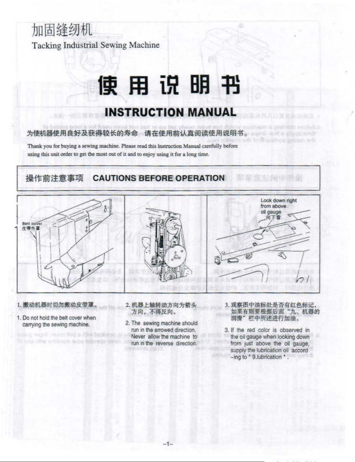
t~Ht:iWl!~JJ!Pi
1.
Do
not
hold
the
belt
cover
canying
!he
sewing
machine.
CAUTIONS BEFORE OPERA TlON
whe
n
2.
The
run
Never
run
sewing
in the
allow
11
the
machine
arrowed
the
machine
reverse
should
directoon.
to
direction.
3.
If
the
from
supply
-
the
ing
oil
just
to
gauge
red
color
above
the
lubrication
' 9.
1ubrlcatlon
is
when
observed
looking
the
oil
o;J
' •
in
down
gauge
accord
,
_,
_
Page 4
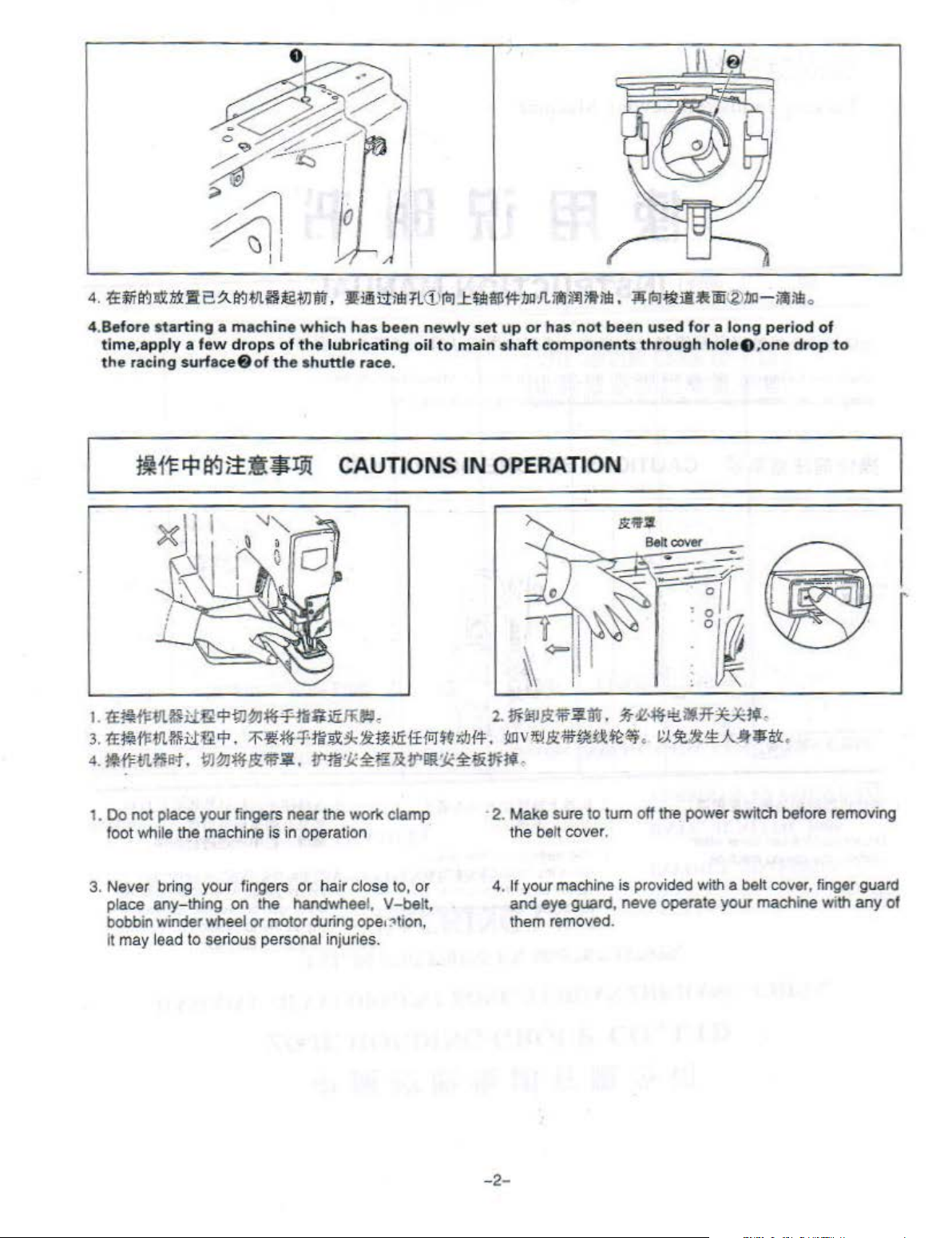
4.Before
time,apply a few
the
starting a machine
racing surface& of
drops
of
the
which
the
lubricating
shuttle
has
race.
been
newly
oil
to
set
main
up
or
shaft
components
has
not
been
used
for a long
through
hole
8 ,
period
one
drop
of
to
HH'f:!fla9jil!4JJ.9l
I.
"tE~fl;tll.$l:l:t!l
3.
'tE
lii!
fl'llt
tHJ:~rp.
4.
M
tll.tli~t-t
1 .
Do
not place your fingers near the
foot while the machine is in operation
3.
Never bring
pl
ace
any- thi
bobbin winder wheel
it may lead
r:f'
W~
~-'F~tti!t
:f
~~
:f
:tli~
.
m~~~~~. ll'm:tc~~&!/'
your
fingers
ng
on the handwheel, V-belt,
to
serious personal injuries.
or hair clo
or
motor during op
CAUTIONS
.fUJ
e
~
2ti!iliffi"J$~
worl< clamp
se
lo,
or
IN
#J
{'l'.
llittc~a
OPERATION
2.
Jli:
~Jt.U
jll]VI.I'litflf~tltt:~
Jii:r.,
· 2. Make sure
the belt cover.
4.
It
your machine is provided with a be
and
eo
~
lion,
them removed.
f~
iltr
.
.*
ok:·~
.
to
tum
off
eye
guard, neve operate
't
-1f
XJ<tf.
~:!e~1:.~lJ~
th-e
power switch
your
,
.
befor
e removing
lt
cover, finger guard
machi
ne
with
any
of
-2
-
Page 5
INST A LUNG
THE
MOTOR
_ ,
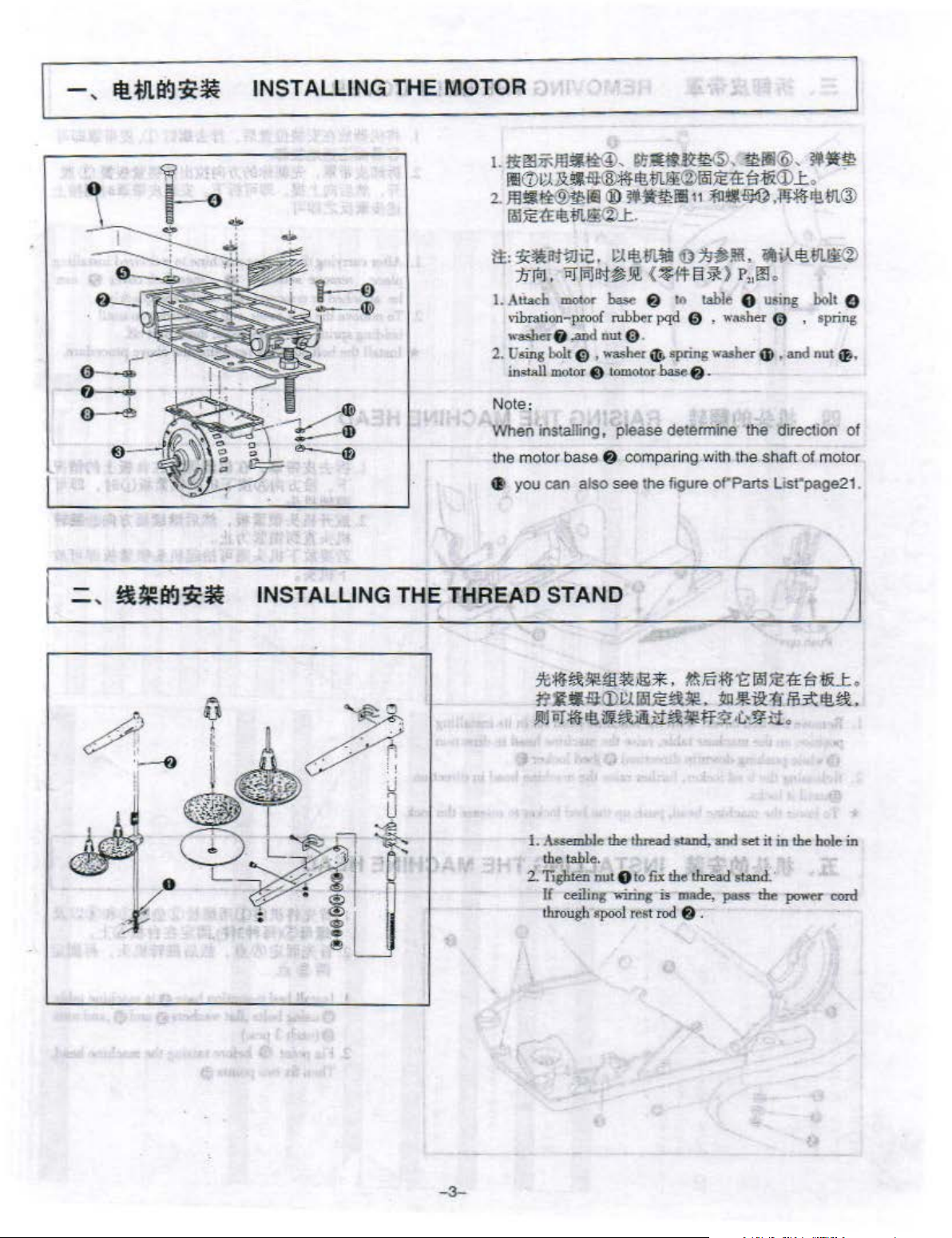
INSTALLING THE
l.ti~;;;.m
~~~~~
2 .
..lll~ti®mlli
fQl~:tEEI!.tll.~®k.
tt::~-~ic,
1f
I.
Attach
vibration-proof
wa...ber 8
2.
!ising bolt
insWlmotor
Note:
When installing, please detennine the direction
the mot
e
you
THREAD
~
~t®-GF.~~,~~~®,~
~~~~~~~~~~
®
~811111
1;.(~~
(.]
,
PJfiljl!<j~..W.,
mol0<
,and
Cl)
,
e tomotor
or
base
cen also s
(
~
~
f)
rubber
pqd
nut 0 .
washer
~
base f).
f)
comparing with t
ee
the
~-~
o~m~.
13
~}
to table 8 U!ing bolt 8
0 , WMher 0 ,
spring
washer G ,
figure
of'
STAND
P
Parts List"page21.
•m
L
o
.
,f!i::ilf~.fll.®
•v..~-lll.li®
1!l
o
11
sp
ring
and
nut
~
.
of
he
shaft
of
motor
1. Assemble
rhe table.
2.
1i8luen
If ceiling
rhrough
the
nut
,.,.;,;ng
•poo
thread
e to
l r
est rod
fix
is
otand,
the
made,
and
set
thread stand..
pass
8 .
it
in
the bole
the
power eon!
in
Page 6
_ ,
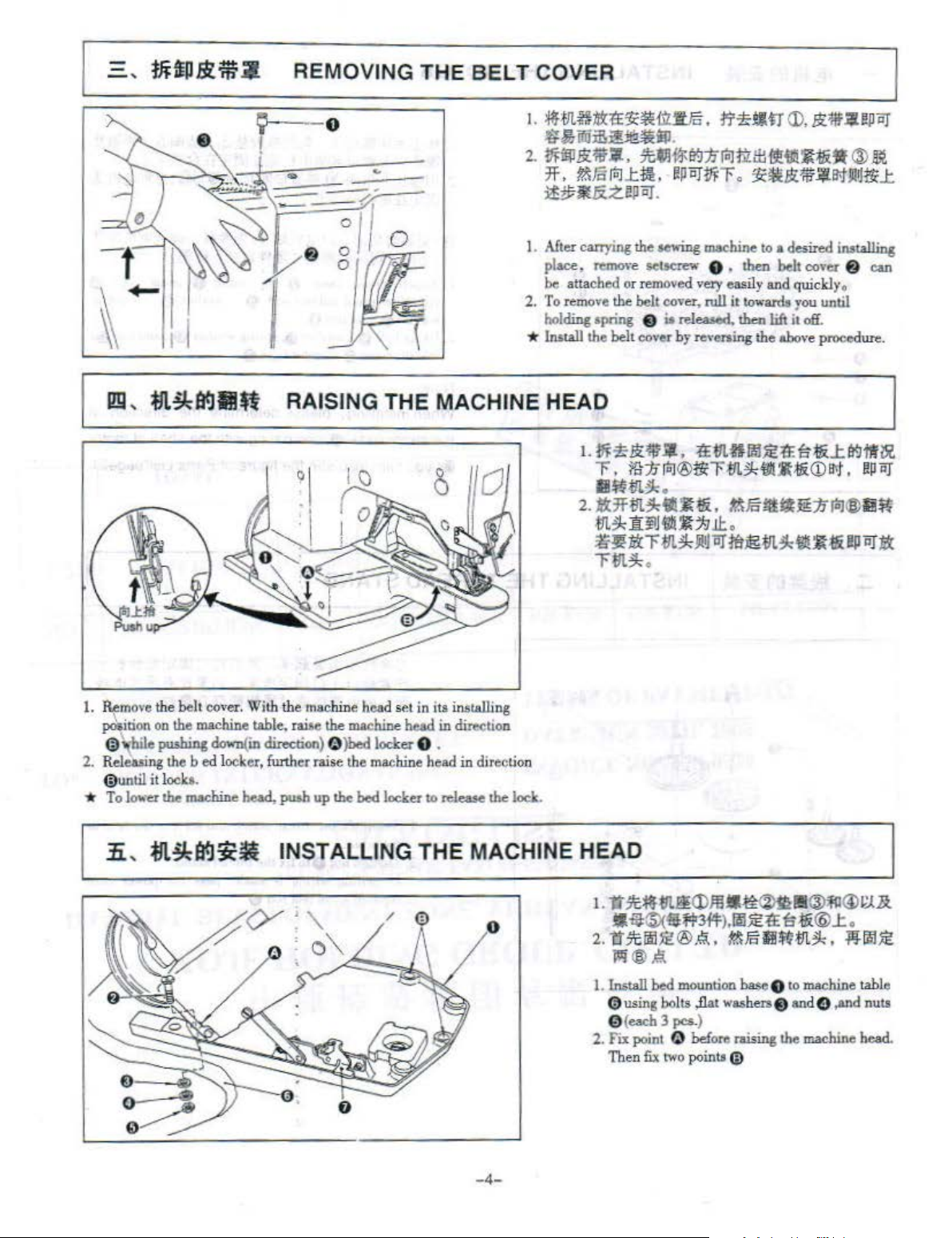
REMOVING THE BELT COVER
~---o
lm
,
:M.!ktfi.JIUl
RAISING
0
THE
1. After
2.
*
carrying
pW:e,
be attached or
To
ho
lrutall
remove lleiJCrew O . then
remove
lding apring 0 is released,
the
MACHINE HEAD
the
belt
the
aewing
removed
belt
cover,
cover
machine
very
rull
by
rever-ling the
to
a desired imtall.ing
belt
cover
easily and quickly.
it
towardo
then
lift
above
you
it
off
.
procedure.
until
8
eon
I.
Remove the belt
~ilion
{il
2.
Rel~ng
{il
*
To
1i
on
the
\-bile
pu-'hing
the b ed locker, funhcr raise the machine head in direction
until
it l
ocke
lo..-er
the machine head,
,
:M.!ktfl.l~~
cover.
With the
machine table.
down(in
.
direction)
machine
~.
pu..h
up
head
set in
the machine hesd
f)
)bed locker 0 .
the
bed locker
to
its
in_.talJing
in
direction
release the
lock
.
INSTALLING THE MACHINE HEAD
0
1. install bed mountion base 0 to machine table
(l)
using
0 {
e3Ch
2.
Fix
point
Then fix
bolts
,flat washers& and
3 pes.)
f)
before raising the
two
points
CiJ
C)
,and
machine
nuts
head..
-4-
Page 7
-
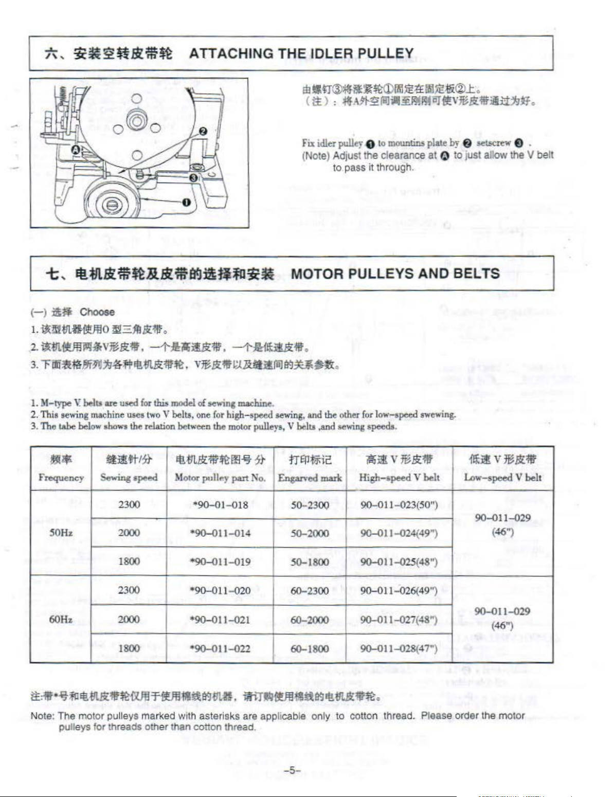
ATTACHING THE IDLER PULLEY
Fix idler
(Note) Adjust the clearance at 0
pull
ey
8
to
to
pass it through.
mountins
plate
by
6
to
just allow
set.&crew
the V belt
e .
t ,
(-
)
I.
~l!iltll.mv!lO
2.
M~*v~&:'lf
3.
rili%i~ef~1i~f+tt!Ail&:1f~,
I.
M-type
2. This
3.
The
F~"""Y
EUII.&:om:~B.!t'lira<:J~ffl~J1C~
:il~
Choose
~-Rl&:~.
,
sewing
t.ohe
JI!M$.
SOH•
\:
~hs
are used
machine uses
below
•bows
Sewing •peed
-1':1!iQiU1f
for
this
model
two
V
~I!Js,
the relation het,.·een the
IJ!l!W?t
2300
2000
1800
El!.m&:;.w~m
Motoc
*90-01t-014
*90-011-019
.
--1'-Hi'ltlt{f
v~&:f!f
of sewing machine.
one
'"
90-01-0!8
for
high-speed
motor
pull~
y
i
;Ut!itj&ruJa!JU~
pulleys, V heltt
.§J
7}
part
No
sewing,
.
Engarved
MOTOR PULLEYS AND BELTS
.
.
and
the
other
for
,and
tr
t:n
m
50-230Q
50-2000
50-1800
r:
mark
low-speed
sewing
speeds.
?aiJ:iV~&;'l!l'
High-speed V
9.0-0
11
90-011-024(49
90-0
11-025{48
swcwing.
~It
-023(50")
")
")
{li:ifV*&;'lll'
lAw-speed V belt
90-011-029
(46j
60H•
Note:
The
motor pulle
pulleys
2300
2000
1800
ys
marked with asterisks are applicable only
for
threads other than cotton thread .
..
90-011
•90-011-021
*90-011-022
-02
0
60-2300
60-2000
60-1800
90
- 0
90-011-027
90-01
to
cotton thread. Please order the
-5-
11-026(49'~
(48")
1-028(47")
90-011-029
(46")
motor
Page 8
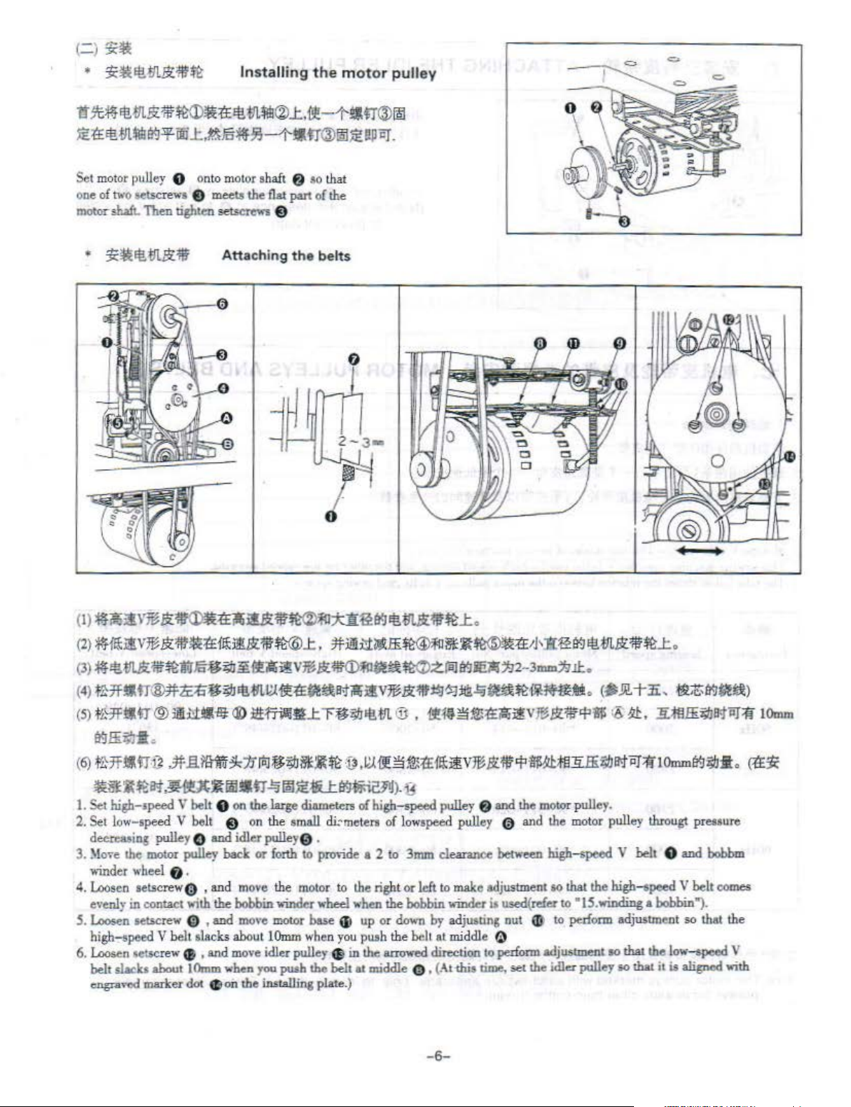
Installing
1i
1C:ml1!411.&1if~~~tl!-ln~®..l:.,{!l!-1-tUT@~
~:a:
ee
m~l'f.l+oo
Set
motor
pulley 0 onto m
one
of
two
setsc
motorsludt.
Then tighten setscrew-& e
.t.~li5:!8-§!--HJ-trCll~~
otor
shaft
rews e meet$
the
nat
the
f.J
so that
part of the
moto
apor.
r pulley
Attaching
the
belts
0
(I)
~~l.l\~&:~~iJ!iU~*ll~l'f.ll~.-flttk:~~l:.
(2)
HJ!V~
(3):meeU'Ii~1V~#;~J3[it•
(
4}
f13Hltr®:lttit::i#~
(5J
:I'Hfltl
&'ll'llil:tEf~iM&:'r!T~l:
IU-111.
l!.l~~ti!~B>till
tr ® JIIH'J:.lii-Bl:
®
l~H
rillifl
.
:lt.iitii~lli~~UH~(~~~'J'
ilv
~J!i.~tl!
i!V~I!i.~~~:lil~~~Ul~mt!.
..t
n;~~ll!.
atW>.Zr'iUI'f.lie1i!:h2
m
IE
•
~~
~~:a~Jlv% I!i.W<~'il!
11::f£1'f.J
-3mm:h!l:.
eetrr.Si'r!T~..t.
(#
JlL
+
.li,
tE
tit.
1LKIIE;~JB>tiiT:fl
~z
l'f.Jf,'ta)
1
0mm
l'f.llE~tt
(
6)
fl}jf
~~~~B<t~~~•n~~~~~~B
I.
Set
2. Set low-speed V belt e
deeteMing
:llo<e
3.
-.;nder
4.loosen setscrewtl) , and
evenly
5.
Loosen
high-speed V belt slacks about
6.
Loosen
belt slacks about I
engra,·cd marker dol
.
.II fJ.
j}
•
.:It
liffi-
lF.
high-speed V belt 0
pulley O
the
motor
wheel
in
contact ,.;th the bobbin
setscrew 0 ,
sellc
rew
pulley
O .
IJ ,
and
and
and
Omm
IE!
'!k
/J
[I;]
f$;1J~'Ut
on
the la.ge diameters of high-speed pulley
on
the small d
idler pulley0 .
back or
move
forth
the
winder
move
motor
!Omm
move
idler pulley
when
you
push the belt
on
the installina plate.)
~
to
provide
motor
wheel
base
when you
1J
·V
,!;.(
-f!1131.2::S:
eometen
to the right or
aJ
of
low
a 2
to
3mm
,..ben
the bobbin winder
up or
down
push
the
belL
in
the mowed dir«tioo
at
middle
(!)
il
i!V
~
&:'liT
<fH;f!l:JifEi:IJI!<J'iiT:fll
f.J
and the
speed pulley 0 and
clearance between high-speed V belt 0
left
to
make
adjustment so that the high-speed V belt
io
used(
by
adjustins
at middle 0
, (At
<his
nut
to
perform
time,
set the idler pulley
-6-
Omml'f.l~::i:.
motor
pulley.
the motor pull
refer to "15.
tD
to
perlorm adjmunent so that the
adjustment so that the low-speed V
ey
througt pretsure
winding
a bobbin").
so
that it is aligned with
and
bobbm
~
comes
Page 9

I\
'
~~~I!;
lei<
w~nr
ATTACHING THE CHAIN
Hook
S-$baped
stArting
S-shaped
lever
hook
.
hook
f)
~
into the hole in the tip of
,and
arU>
ch cbaia 0
to
I
th
e
JL,
f!
Ill
fi
Jilt!f!li!llt
I'
r.J
idl11.
*When
S
urply
<\ili<"nn
.
-\t
thi<\
timP
-t-,
i
1i1fft
~
1Jo)l.
using
""
...
r.
bHk r
tJL$-~~fF
LUBRICATION
«:~Hii
ii
illl.i!lt-ttUf-
the
nil
t
hrough
hCJ
f;l Btll:e :
thread
tthe
guide a
~mc"f'lrtP
thr~>a
d
OPERATING THE SEWING MACHINE
"Fe
nilluhri~ari
whi('h
~ilti:t!t
synthetic fiber
h.-~
ng
hol.-
f'iJSi>eo !
1:
.)(!
thrnu
fiiJ
thread
@)
"·
gh t
t.lt..tiii
hf':n u"m8
hrea
.:!Hilfiiidl.
and
cloth
thr
..
.ul
gu_ifi,.
cl
guid~
()
I_-
.Lubricate
lubncanng oil through lubricating hole 8 ' until
the n:d color in
-ears
2. Use oil for
ha!'!
Lht:
as
observed
0 for a
P.
illrnne oil
th~
machine once
oil
gauge 0 completely
from
sewing
machine.
~~
'Tl
lhf"ti
1"'111
c-
fi1w__r
it.
right
thread
e'VeJyday
above
the oil
. Supply the
daapp
PU&e.
!lfl'lnfi~:trar,
1 . n *
!l!il;af,9::
2. fl1tl
fii!1r
.i&;IJiltit!i
3.
Ji!!l~Ui;~Jlli:;IJ~!&.
4.
~
.\tt11.~7'fl&-
Operate the sewing machine in the
1. Tum
2. Depress the starting pedal a little, and the .. ·ork clamp
3, further depress the pedal,
4. When the machine has
on the
powe
release the
release the pedal.
and bobbin threads are trimmned befon: the machine stopo.
pedal.
.
.
,
Bi:!lll~fl.
JMln.ffl!ll7fM!ttit,
1'
.1mm!jGSHiJB;f,
r switch.
and
comple
~a~.lit.M\USI!Jifi.~.
i!lt-tJii
~l!lliHi
following
the sewing machine starts bar-tAcking. Immediately after the sewing machine starts hartacking,
ted the specified
f#J~~,
procedure:
bar-
§ltJ$:3f
!'!j~ffaiP~~.
ID!ill3~l'it®.
foo
t
will
come
Uicking
cycle. the
-
7-
~~
!PDJ
do~o-n.
When
you
work
clamp
foot
e
want
will
to
make the
automaitcally go up. and the needle
work
clamp
foot
go
up,
Page 10
(it~)
1.
~.m.H1f.ltit1Tlilill<t
iiiJ
iit
iJ:
~-B*·
2.
~a~~Jc~nuc~&.
Jc~i!!!liHBJllW:liH
3.
~~~i!irl;!~,
Ji'
W{ff
i!
li<:*~Q(J~!k/rt-lw~$ti!~
4.
~m~:te~iiiJJ[l.
mlll!alift,l'£l!Mlltr.
-¥i9J~~fi:
~*~··r-~iiiJL~.~!k/rt-J~~~~~
.Bi~UPfH,
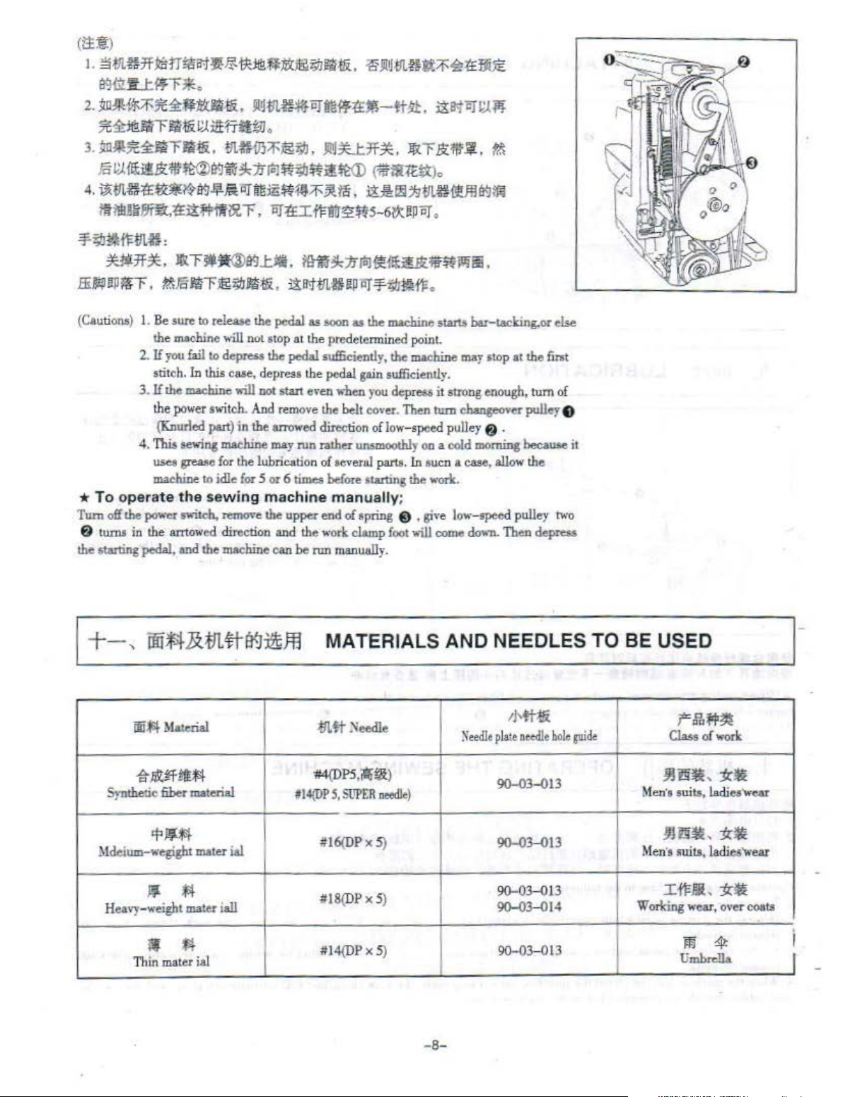
(Cauti
ons)
*To operate
Tum
off
f)
t
wm
the starting
f.llFc
I.
Be
the
2. H
you
stitch. In this case, dep
3. H the machine will
the power switch.
(Knurled part) in the errow
4.
This
uses grease for the lubrication of seve
madUne
lhe
power
in the azrtow
pedal,
~~
~i!!!~:$:J&i9Jm;~&.
J!4~:1ffOJD9fd-ft~.
r
ftlliJ
.
tll.H'!'J§~.
lit
BJ
~
iii~:f4-'f'
OJt£I~~ffs
ifl"il!l
z;i.J
B!Ii
:i&.
sure to release the pedal as soon as
moclrine
sewi"&
the
swit<:h,
and the
will not stop at the
fail
to depress
machine
to idle
for
sew
ing
rtmO\"e
ed
direction
moclrine
!he
res
DOl
start
An
d r
may
5 or 6
machine
lhe
4lld
can
.Jr~JU1f~.
9t m •
i!ll<ttrl.ti
pedalsuflieiently, the maehine
s the pedal gain sufficiently.
emove the belt cover. Then
run
times
upper
the work clamp
be
!!P
prede~
ev
en
when
ed
direction
rather
unsmoothly on
before starting the work.
man
end
of
run
man
~
Jtu.m.mt~4ltl'£til~
i!s-tCJ
~;~.
:ffn
E<:"ii'
!t
.
('?.fS~tt
l:ki!:llil
-
6V::!PCJ.
iiT-¥z;IJ~tF
lhe
machine stariS bar-tacking.or
rrnin
you
of low-speed pulley
ral parts. In 1
)
o
:'htll
~
.
ed
point.
de
press it
stro
tum
a cold morning because
ucn
U
Q(Jffil
~
.
may
ltop
ng
eno
changeover pulley e
f)
a case. allow the
ually;
spring $ , give low-speed pulley two
foot
will come
ually.
down.
~
ft.
at
the
lin
ugh,
tum
.
Then depress
else
t
of
it
+-,
ili*'l-.&
iii$~
Ma!erial
it-~
§ff!t$1
Synthetic fiber material
'f'Q
Mcleium-wegisht mater
111
fl
Hea,-y-weight mater i
~
•
Th
in
mater
ial
t!L#
(!(J~
i&l
all
Jij
MATERIALS AND NEEDLES TO BE USED
/
-lnft
'#4{DP5
1
14(DP
#16(DPx5)
#18(DP x 5)
#1
:'i'eedle
,i0i
!;i
S,
SUPER netdle)
4(DP x 5)
Needle
)
Mt;Ui
plate oetdle
90-03...()13
90-03...()13
90-
90-03...014
90-03
hole pide
03-013
...0
13
-8-
f=,ff,
f'jl
Cia..o
of
~29~,
Men
's
aui
t.s
, ladies'W
~13~,j(~
Men
's sui
t.s,
ItFJliL
Working
wear, o
ji[ij
Umbrdla
~
work
:tc
ladi
:tc•
~
rt
es'
wear
ver
coa
car
ts
I
I
Page 11
+=
,
fll.
tf-
99
~~
ATTACHING THE NEEDLE
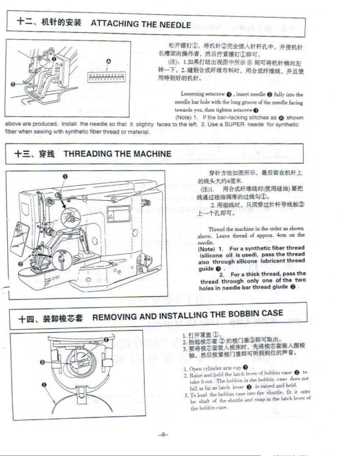
above
are
produced. Install the
fiber when sewing
+~
,
~~
needle
wrth synthetic fiber thread
THREADING
so
THE
~~~
thai
it
or
material.
MACHINE
;
.f'C1f~na>.
i'::I!JiliiloJM=if.
<
!::!:>:
~.:m~rr!tlt~~~l!l<PP.JTii<
~-r
Jli~jiJ~t~Stn#
shghtly faces to the left.
.
2.!Htft~itf~~*4111.
loosening
needle bar
towards you,
(Note) 1. If the
~t~t~~~!fi.AtUT1L<P.
?&Fcti':l!lfl<DePar
.
seL<;erew
hole
then
2.
Use
~~~:;titJ
(i::I:)
!iliailt'i£l!!!ilil11t~~1;J(J).
C.
, insert
,.;th
the
lo
ng
tight
en setscrew Q
bar-tacking
a SUPER neede
~#n
~~m~~.
4
fi.
L
ffl~nlt
2.
Jli!S!iat.
.
®
Jlllor:m.mttm(u)1c
JIH~IRitfU.
needle
groove
of
Stitches
aFa~~111.#L
i'H
.t~Ji:t(
Jl.1J!$
Himf.!';!i-\!i®
Jftttn#
#il.it
@
fuUy
into the
the
needle
facing
as
Q shown
for
synthetic
~Jii
lel!!!)
JH~
.t-1'5LRPilJ.
-
+1!!1
,
·ill·~-
I
·o
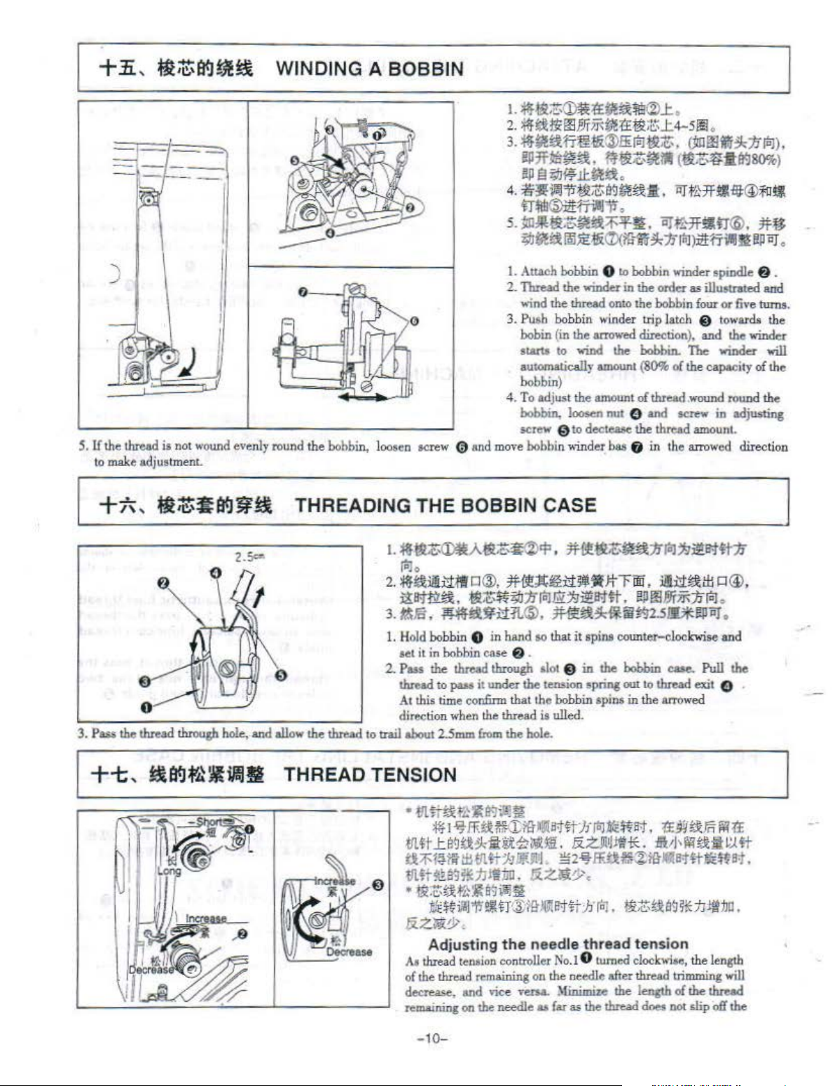
Thread
above.
lhe
machine
Lea,·e thread of approL 4em
in the order as
needle.
I
(Note) 1. For a
(sili
cone
oil is
also
through
guide
e .
2. For a
threa
d t
hrough
holes
in
needle
synthetic
used
},
sili
cone
thick
only
bar thread
fiber t
pass
the
lubricant thre
thread, pass the
one
of t
giude
REMOVING AND INSTALLING THE BOBBIN CASE
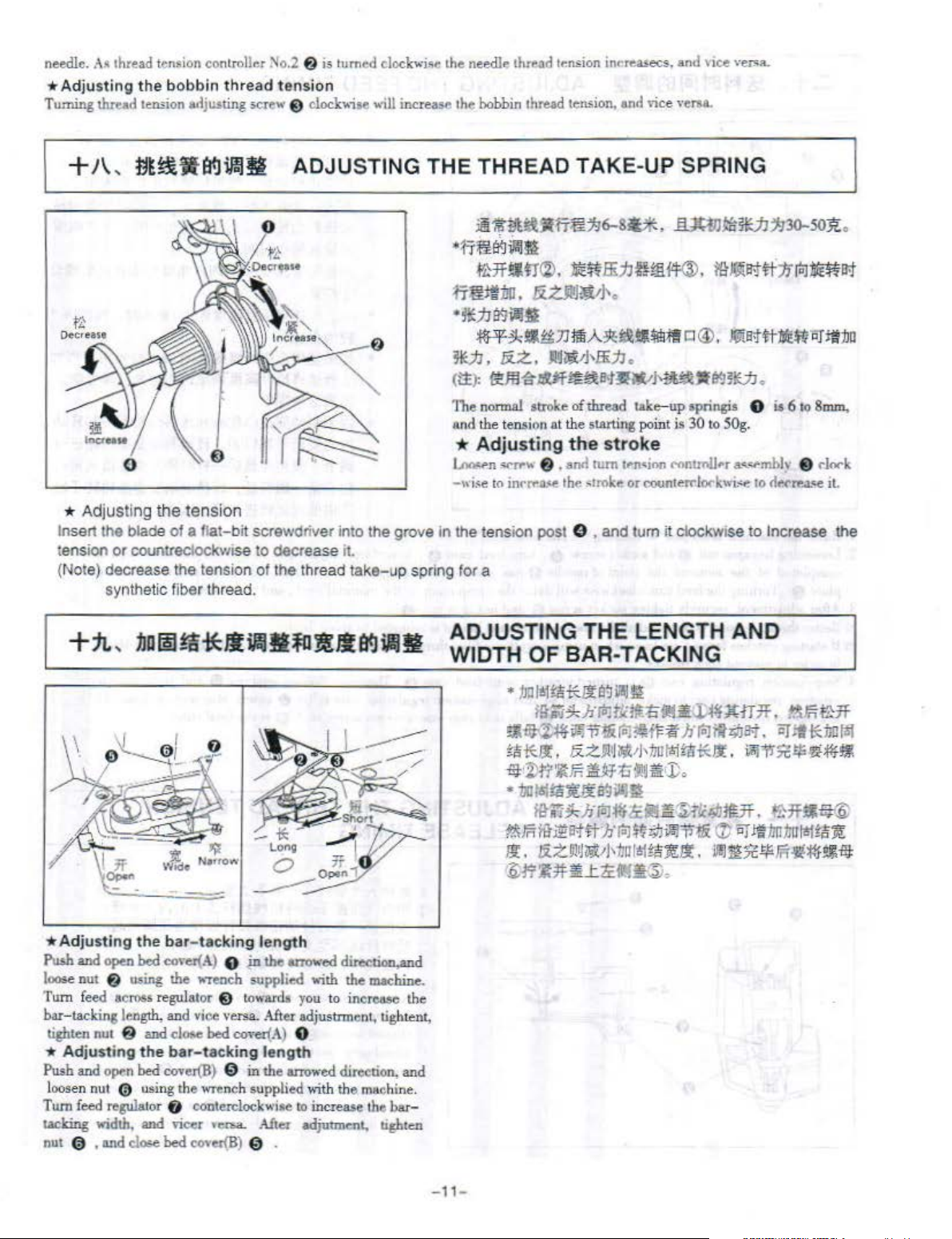
I.
OJ"'
II
.,
ta
k
fall
T<>
hr
thr
·lind·r arm
.
f'
11
nu . ...-
••
far
!..ad
t.haft of
hobbin
t
a•
th•
2. Rai;.t. and bnlcllht' lat('h 1 ..
3
.
Th
latrh
l>oh
&ht>
('a_V
...
Lh
nu
hin
iihutt1(':
.
rap
e .
,.~
hin
in
lh,.
.
'"""
E)
ra"' int<>
anrl
,
n{
J;.,~hnt
h()h
hm
f"~tlu~
i•
rai•.e<l
and
tl..-
•hun!•.
-.nap
tn
lhf' l•tt'h
shown
on
hread
t
hread
he
& .
ra..:,t"
do~~
hrld.
fit
the
ad
two
& tn
nnt
ot
ont<>
1~\'Pf
nf
-
9-
Page 12
S.
+li
II
to
)
the
mak
,
~;t;~~ti
thread
is not
wound
evenly
e adjus
tme
nt.
WINDING A BOBBIN
round the bobbin, l
oosen
screw 0
1.
Attach bobbin 0 to bobbin
2.
Thread
wind
3. Pu&h bobbin wi
bobin (
starl.l
automatically
bobbin)
4.
To
bobbin, loosen
ocrew g to
&nd
move bobbin winder. bas 8 in the
the
winder
the
thread
in
the
to
wind
adjust the
in
onto
nde
arrowed
the
a:n<>unt
a:n<>unt
nut
dectea&e
0
win®
spindle 6 •
the order
the bobbin
r trip latch @
direction), and the
bobbiJt.
(80%
ofthresd.wound round the
ami
the thread amount.
as
iUU5trated
four
or
five
towar
The
wiode.r
of
the eapseity of the
screw
in
adjusting
arro
wed
direction
turns.
<Lo
windel-
ami
the
will
3. Pass
+t
2.5<&
the
thread
through
,
~~f~Wfi?.J!l
hole,.aml
allow
THREAD TENSION
THREADING THE BOBBIN CASE
I.
the
thread
~ttt~{~;~~cp'
tolo
2.
~~liti1~CJ@,
~~~.~~~~:fitoJ~~~~~.~m~:fitoJ.
3.
~.16'
~~:1111..®.
1.
Hold
bobb
in 0
set
it
in bobbin
2.
Pass the
thread
At
direction w
to trail about
•
.tll.~H.Ii~~!kiitilt~
ii;f~r.ftllt11WJ.J~~l
tJl;r~s~~
•
&z~&
thread
to
pass
this
time
hen
2.Smm
tn>
,
!!llt~ae:Ji.l!JJ.t
:!if
I~
~:t:~tG~a~Vil!!
trE~ii&l~!!l.tr@ltf~Bt#
.
Adjusting
At
thre
ad
ten•ion co
of
the
thresd remaining on the needle after thread trimming
decrease,
remaining on
ond
~~;lt~lfl!UlJf"F
in
hand
case
a .
through
it under the tension spring
confinn that the
the
thread is ulled.
from
the bole.
.A\
ill
~ii}
;t.J
Jtim.
the
ntroller
,;ce
vena.
the
needle
m!~blitol~i!t~li
~~lii~2.SII*!!JiiiJ
so
that it spins cotmter-eloc
slot @ in
bobbin
Jt3it~
ft
:/i
~Jai
.
&ZJ!•
22~
~Z.~?.
:
h'M.
need
le
thread tension
No.I
0
Minillliu the length of the
as
fu
a.s
the
ilii, :i!li~lll
the
bobbin case. Pull the
001
to
thread
spins
in the
arrowed
tol~
~Bt.
:G:91
llt
*.
S\'J'M~1'ii~~
ID.l~~iirJIB:tft!liffBt,
t!li:Z~a~*JJ:lt!JD.
turned
clockwi•o,
a®.
.
lcwi
se and
~~ 0 .
~Fn
W
H%
the
lensth
will
thread
thread
does
DOl slip ofi the
- 10-
Page 13
needle.
Turning
A~
thread tension controller No.2
*Adju
sting
thrud
+
/\,
*
Ad
justing the tension
Insert
the blade
tension
(Note) decrea
or
synthetic fiber thread.
f'J
is turnf"d clockwi!;e the needlP thr ..
the
bobbin
teruion adjusting screw E) clockwise
~UUftllJiJ!)g
of
countreclockwise to decrease it.
se the
thread
tension
ADJUSTING THE THREAD TAKE-UP SPRING
a flat-bit screwdriver into the grove
tension of t
he thread take-up spring for a
will
increase the bobbin thread
im
~iJUl)l~'i'
·~flei.Jiill§
~*~~~.
n:t~
il!
illl.
·
~}J89illl§
M
3*j]
'
!9-Z.
(tl:):
~~
The normal stroke of
and the tension at the
*
Adjust
~f"n
~11"\\
_,
,
i~e
to inrfftl$-e the
in
the tension post 0 , and tum
.ad
tr.nsion
in<"reasecs~
ten.<ion,
<b!
~U
&.<:ml!£,1-
~«iiJJ
lSiA
•
~l!;Xtl\!li~.
.ll!tif
~
and vice veroa.
7:16-SU,
ffi~fi~~.~~~
.
:lll:~
a.tJ-'I!ltNit.~
thxead
stArt
ing point is 30 to 50g.
ing the
6 • end
stroke
turn
lf"'n~ion
:-otmke
or
and
rut:W.tili!UJ
tl~;fl
lak
e-up
t•<mtmU,.r
counterrlO<'kwi~
it
clockwise to Increase the
,;ce
ver.:;.a.
1130-SO
~n
a@). ~~
-
eeJ~IEJJ .
springis 0 is 6 to
#
~ti;PJ
a-••.••f·mblo;
to
t!t<>n"'A.~
:it
.
~~~
l:lt.1JD
Smm.,
t)
r)CW'k
t
l.
*Ad
justing
Push
and
loose nut a using the ..-reoch supplied with the maclllne.
Turn feed
b
ar-ta
cking
tighten
*
Ad
justing the
Push and open
loosen nut @ using the wrench oupplied v;ith the machine.
Turn feed regulator 0 eonterolockw
laclring
nut
@ , and close bed eoHr{B) 0 .
the
open
bed
across regulator
lt.n
gth,
nut a and
bed
.ndth,
and
bar-tacking
<ȴ~A)
and vice versa. Aft
clOi<>
bed
bar-tacking
cover(B) 0
viC<:r
length
0
in
the
E)
towards you to
CO\•er(A)
length
in the
'"'""-
After adjutment, ughten
arJ'C)Wed
er
directi-d
in
erCMC
adj ustnnent, tightent,
0
anowed
ioe
direction, and
to increase the l>ar-
the
ADJU STING THE LENGTH
WIDTH OF
•
Stiilt'l.#fi!Al11~
~~*JJ:,
"l:•2lfi''lJF.~.A'f~~U~
•17aftll:a1t!i~lill~
r.&Fn
~.
~l1':l*~J:timffi~,
BAR
J;oJt!1ta
Hl~:!kh'
-TACKING
*
ll:e~illlm
tcltJilft:b
tllliJAlf
~ji,H
1'.W h ~ifl#J<J;f.
liZ§l']i1tt)•1itlftlitl*iJ: ,
•
J:o
iit~:!I-Ji(o)~<Xii!!~~Jc4Jillf.
lit
.i2!a<l#
!iZJi!lj~;J•1lUh!f
h'
~~~~Tit&
~~
Jl:.
(!) 'iif
iiiJfifC
AND
A-iT
.7f
•
t!Ri~.ff
iiflt
~:1m~
~11'51!.!/i~.#f
~m~ilP~
Jt1m
1m
EF
Fri.fi!~
§l
ftll:a
~
~-Hl:
-1
1-
Page 14
=+,
:i!~lt..tl'li.l~if.Jfl
Delay
I I l
L Raise
2.
3.
-a
*If
4. Stop-motion
the
Loosening
compleud
6 . Turning the
plate
Aft
er
edj
ustm
Better
thread
.wting
in
order to pr
mAChine
hexagon
at
stitches
head.(see"4.
nut
the
moment
ont,
securely
ten$ioa;. obtained
formed
even
t such tro
reculalin&
-motion regulating cam 10
low-speed
revolution
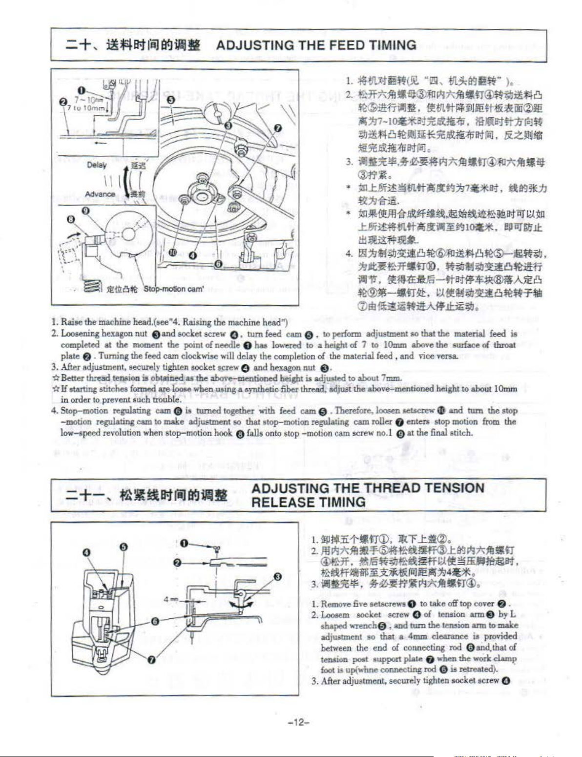
ADJUSTING THE FEED TIMING
Stcil>-m<>tion
Cl
feed
are
cam 0 io
when
cam'
Rai$ing
and socket screw 0 , tum
the
cam
clockwise
tighten
loooe
uble.
molce
stop-motion
the machine head")
point of needle 8
will
soc
ket screw 0 and
as
the alxwe-mentioned h~t is
when u•ing a oyntbetic fiber thread.
~
adjustment
hook Q fa
feed
lw
delay the
together with
so
that
otop-tn<>'ion
lls o
cam
lowered
completion
hexagon
feed
= 0 .
nto
stOp
-motion
1.
2 .
3. liii§JC
•
•
4.
0 ,
to
petfozm
to a heisflt
of
nut
C).
edj~oted
regulating
of
the
material
to
odjw
t the
Therefore,
cam
cam
scr
~.tWintiJl!.
.j.ffi~fidJ~J;Ij~:ffdltr®*~ilUlft)
~l£~-Till~,
)1;1117-l~lt..tU~:{f;,
~iUi8~!i!llm*S:Ckm:{f;ll<tfiil.
~~~~.:{f;f!;jfBlo
!!J1.~1l·~=llfJ;Ij~1f!tltJ®f:o~~Ul-st
~~0
~li'i'i:i;?41-!Ji#tli!r~}J7Uat.
~111ni.
~Hili~
.tilf
~:t6'-Vl.
tlllli!.ffll~
flil1JiM~~J!t)~;f!IM8~.e~.
1J~~~*Stf®.~M~~8~fi
~~.~~~~-ttlt..t~$~~~8
"@
,
m~t¥JI!n"
~-Vt
ttl'-¥i1Jie:
l!t.QI>t#1n~Jft
.i&~!!l!t,Wil~:i!l:-f'CJ;f!;j<iJ
tt11fll·:1E~
IOit*. l!jltl]'fitj
>·
~t.f&
:
<IHii®ie:
&zJi!~ilil
~ll9*.1J
VJ~
J.!:
~~--tr~.~~~~~~8~~T~
(L)
EI!~NAifJ.!:;E~
adjUSlmelU
7 10
feed
about
above-mentioned
loosen seucrew e
roller 6 enters stop
ew no.J
IOmm
, and
7mm
0 at the
to
that
the
alxwe the surlace
vice
versa.
.
height to
final
material
and
motion
stitch.
.
about
tum
feed
of
the
from
i8
throat
1
Omm
stop
the
ADJUSTING THE THREAD TENSION
RELEASE TIMING
0
0
0
6
=:r-_
!
L Remove fi<e
2.
Lootem
shaped
wreneh
adju•tment
betw
een the e
tenoion
foo<
3. After adjustment. securely
poet
"up(whne
-12-
oetoerews
socket screw 0
0 ,
oo
nd
•upport
8 to take off
and
tum
that a
4mm
of oonneeting
p~
connecting
top
of
~nsion
the
tension
clearance ia
rod
0
6 when the
rod
0 is retreated).
tight
en socket screw 0
oo,·e
r 8 .
ann 8
by
onn
to
malce
provided
and.
that of
work
clam~;>
L
Page 15
=+=,
0
tJI.it~flfltf.J~~
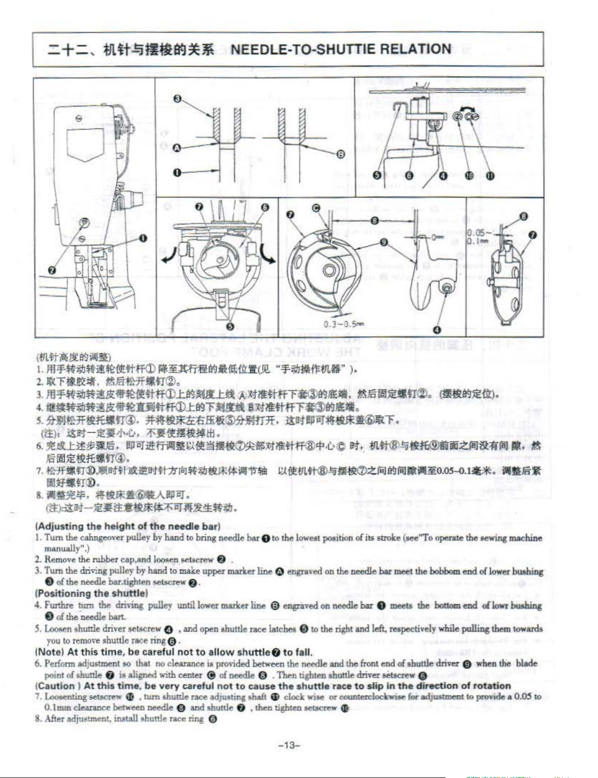
NEEDLE-TO-S
v
HU
TTlE RELATION
0.
3-J.
S=>
(tll~i*itt~~~)
1.
JIPJi·~;;i.J*ll~l!1!ttff<D
2.llltT~~~,
3.
JD'ff\';IJ~iU'Iif~f!fl-ff<D~;mJJL.t:a
4.
~~~~1iHI),Iilltt#<D..ttl9"'F~U
ti.\JiifBfJl.n®o
s. jMIWHfl:QrutfT®.
(~· J:!l!;f
6.~~$~.
~m~~~
1.
f~*•n®.~ll't~
-https://manualmachine.com/
-"·C.
•n®.
1
I!PliTi1Hnlll
~~ottt:nM
~~M~BIJ:effl:-utJl(.!l!.
..iJ~I!HtffT~~ffl:-.
"
'3'-;;i.Jifk
fll-!ILf&"
l·
~.X'fl!HHfTMWljjlj
Jt~~:O.Ii:fi~tHJ:.
•. :f}l!~l!tl*lfl
m
l!.t~~~~~$~llmff®<P
·
~;;DfilLf:jll>:\flll"~
i!ll't~or~~"F.
·
C.·©
ll't.
Q.t
~mft-®~
m~cr>zreJ
f&JiiWU~~.
.
-!IL#®.!;jtQft®uumzreJ&:Hiill•·
·
~
fi;J
lilmltr®.
8.
ill§l~£#'.
<tt>
:l1a;t
(Adjusting
l. Tum the cahngeover pulley by hand to bring needle bor e
manually".}
2.
Remove
3. Tum the chhing pulley by hand
e
of
(
Positioning
4.
F'wtbre
e
oi
S.
Loosen
you
to
(Note) At
6.
Perform
poinl
(
Caution
7. Loooenting setserew
0.1
DUn
8.
After
~~l!PPJ
-
~~tt•~~nttiiJ.
the
height
the rubber eap,
the needle bar.tishten
the
tum the drmng
the needle
shuttle driver
remove
of
adjustment, install shuttle
shuttle rMe ring
this
time, be
adjustment
shuttle
clearance
) At
f)
this
shuttle)
bart.
se~rew
oo
that
io
aligned
time. be
«;
between
of
the
needle
And
loo..e.n.
!"'tserew
to
make
$015Crew
pulle~
until
G ,
@.
careful
,
tum
needle @ and shunJe
not
no
cleorance is provided
"ith
center @ nf
very
careful not
shuttle rnce adjusting shaft
race
.
bar
)
to
the
f)
.
upper mader
f)
.
lower
mader
and
open shuttle race latches 0 to the
to
allow
ring 0
line
~
engroved
line @ engraved
shuttle
needle
to
f)
f)
to
fall.
between
cause the
, then tighten
the
0 . Then rishten shuttle driver setscrew 0
~
clock wise or
lowt$t
poeition
on
needle
shuttle
SOIKf<:W
of
i!S
on
the
needle
needle
bar e meets the
right
and left, respectively
and
the
front
race
to
slip in
oounterclockwise
~
stroke (see"To operate the
bor
meet
end
nf
the dir
~~Ul).
m•?£o.os..o.t**.
sewing
the
bobbom
oh11ttle
ection
for
adjustment to
bottom
while
pulling
dri•er 0
of
end
of
lower
end
,.lowr bushing
when
totation
providf>
i.111!1Fo
machine
bushing
them
towards
the blade
a
0.0.5
ti.\
:xt
to
-13-
Page 16
=+
=,
fi~JJ~W-1§
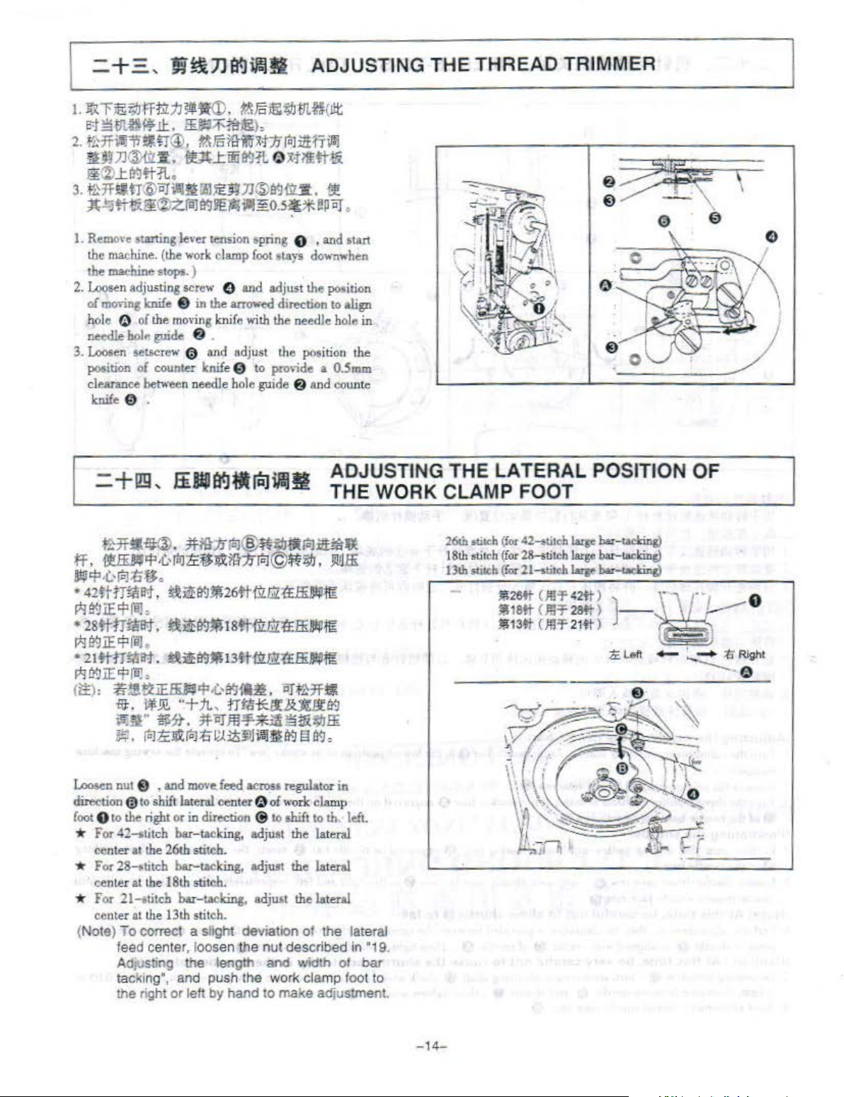
I.
Remove swting
the machine.
the
msebine
2.
Loosen
adjusting
of
mo,in!
0 of the
hole
needle hoi, guide a .
3.
Loosen
position of counter knife 0
clearance between needle
sel<C
knife 0 .
lever tension s
(the
work
stops. )
screw
knife 8 in the
moving
row
0 ond adjust the
ADJUSTING THE THREAD TRIMMER
pri
ng
C)
,
and
st•rt
clamp
£oot
•l4ys
downwhen
()
and adjust the position
~
knif e ,.;th the needle hole in
hol
direction
to
provide a
e guide a end counte
poo
to
ition
O.Smm
align
the
ADJUSTING
THE WORK CLAMP FOOT
Loosen
nut @ , and
direction {i)
foote to
to
the
right or in direction @
* For 42-stitch bar- ucking,
center at
* For28-.btch bar-tacking, adjust the
center
at
* For 21-ttitch bar- udcing,
center
at
(Note) To correct a shght deviatiOn of the lateral
feed center, loosen the nut described in
Ad
JUSting
tacking
the right
move.
feed
acro_ss
regulator in
shift lateral center 0 of
the
26th stitch.
the
18th
stitch.
the
13th
stitch.
the length and width
', and push the work clamp toot to
or
left by hand
work
clamp
to
shift to th. left.
&dju•t
the lateral
la
te ral
&djmt
the
lateral
to
make adjustment.
of
"19.
bar
THE
26th stioch
t
Slh
stit
ch
13lh
.U.:b
LATERAL POSITION
(Jor
42;titch
(for
28-sti~eh
(!or
21--stilcl>
.!il26
tt
*16ft
J!i13tt
laqc
bar-tadc
large
bor-taclci"C)
~
~
(}!!'f~2tt)
(J!!'f 28!t)
(J!l'f
21tt
) - I
inl!)
)
w--
--
~
1.&~ -~
· .. , 0
OF
---
;t;
Right
-e
-
14-
Page 17

3. Pu$b
4. Securely tighten socket
5.
(C.ution)
down
L-shaped
If
the right and left
pl6te 0 to
Be
If
the
le•·el
careful
work
"'Orl:
them.
not
clamp
wrench 8 to
ocrew
0 after adjustment.
clamp feet are not
to
cause
work
foot
lever supper plat" interferes
ADJUSTING THE LIFT
CLAMP FOOT
increase the
leveUed.
clamp
foot
.!EBIHil
;t;At;i;:
1.
:e:tn.ft:fifF·!'iil5t.r.
2.
J'ft
J;~:J
r-~
lli-'F~.
3.
lliJ
r
mi9JJ;~:J;F;~
lliJL~J;~:Jr-~
4
.111
!1Jf$.
5.
~O~li:;t:;ID
§5m~i9Jlli@,
·
(it):
!1!:~
~~~~ffHT~.ar~~tr®~~m~~
ffl)g
iii!f
The
lift of the
I.
'll:'ith
the
to
take
ofT
2. Apply L-shaped wrench 8
on
d loosen socket
lift
of
!he
work
clomp
fooL
or
pull it
loosen serew 8 and adjust the
lever •upport plate 0 to interfere
with
the wiper, readjust the height of wiper using setscrew
OF
THE WORK
OJ
llll31:
17ll*
tm!1l
l1i
~.
~+®.
~~WJ;~:Jr-ffl•n@ti'~.
!
Pf~tE-1'7)(lfiliiJ;I:J.
~~
.;1Jl!i®!9
0
work
clamp
ma<:hine
top cover 8 .
up
pooillon
with
feed
,
lfl:rli-t
.;IJllifl!ffa<.J
~ar~~~&
<~Jfl
!!Par
~~JE~
CD,
J;f:JMMI~@
lliJ
fBHitr
~~~li:~ffi.
foot
in •top
screw.
to decrease the
bracket 0
~tt-1'7)(lfiliiJ;I:J.
f.fi!!IJ~ll
eao be adjusted
mode.
remove
to
socket screw0 of clamp$
lift.
of
work
clamp
'Ff.Y,
five
foot
ll'lr
..tJft®.
.
.t:J&.&•ll ;
.
<1>
.
#til
~D
;!II:ffi.
up
to 17mm.
oet5crews
lever support
e
Gt
ADJUSTING THE SAFETY PLATE
(Wor~
R\11/ll~r
I.
tr~~!(ff(~)J!Ifilllll.
~~M.~~~~~~~~~z~~•
llilliil~v
-~& ~ ~
I.
Loosening
0.2
plate 0 audlifring lever 6 when the
at the tnne of stop motion, and a
clearance between
uo.2
..o.s
~
li.B!illl*~t&zliijW.iaJ
two
se!Serews
to
0.5mm lateral clearance is provided between safety
them
~:til.~~
*.
w~.!EJ!l!~st.
Jl:I
f!ij~
V~J
.lE:
fl;.
1.s-
.liJIIi
2.5ii*·
8 , perform adjustment so that a
work
clomp
1.5
to
2.5mm
lo~tudinal
when
the
wor
k clamp
foot
cltmp
~~
foot
is
i1
down.
foot
up
"down")
2.
~~ittr~.i:J:~<P.
~~~~~~~~
raJ
liil!lt:l!~~l
2. Check that
safety plate e and lifting lever &
2.5mm
during the high
,..ork
clomp
.5-2.5~*·
the
longitudinal clearance between
foot
is
down).
{l:EJiP~Tllrfi!J
~
~z~fi!J~
-speed
bar
taelcinc
io
1.5
to
(the
-1
5-
Page 18
I =
+t
Jl!l}
.!ilL
Appli
,
ti*#~
Model
#I
cation
M
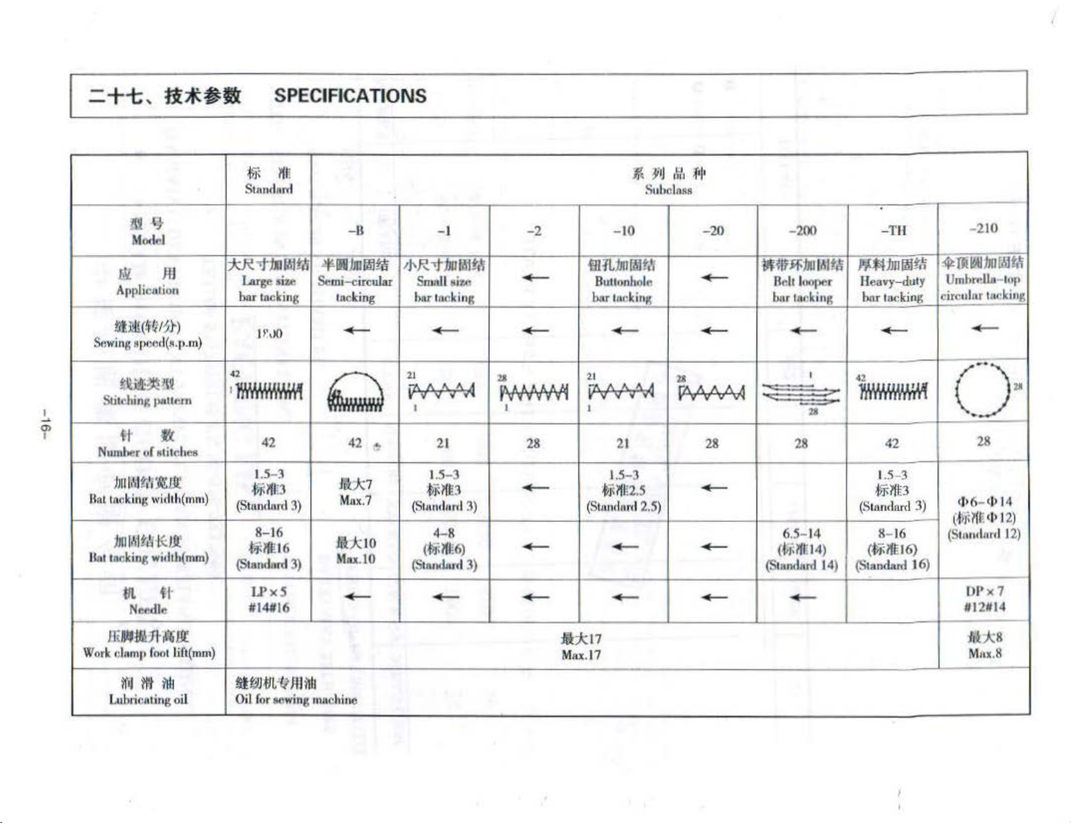
SPECIFICATIONS I
llll
~
St
nndom
"<f"
1JIIII
Larg
e size
bar
tAckin
g
ta
-8
~
IIB
JIII'M
ta
Semi-c
ircular
la
cking
-I
;J-.R-..t:tmfM~
Small •i
bar
zc
tac.~king
-2
-
~
:I'
)J
Subcla
- 10 -20
iH
1L:IliiWM
Bullonh
olo
bar tuc
kin
g bar tnr.
M,
ss
;f•l•
-
-200
~
llf$F:IIJ
B• h l
IM
~
oope
r
kin
g bar tac
--
-TH
J'»1:1mWl\~
Hea
vy-duty
king
-210
~
Uie~J
bn
UmbrPIJ3-l
circul
ar tt•e
r~
u"
OI>
kin
g
.!.
I
"'
!lUli(W?r)
Sewing
8(
)(;(l
d(•.(>.m)
~i!~ll'l
S.:i
tching ,,..u •
fl
Num
ber of •titches
)JIIl
.ll
Bat tucking width(mm
;h1Jih1f<H<:
llal tA
clcing
61.
Nefflle
ffi
llflf.IJtill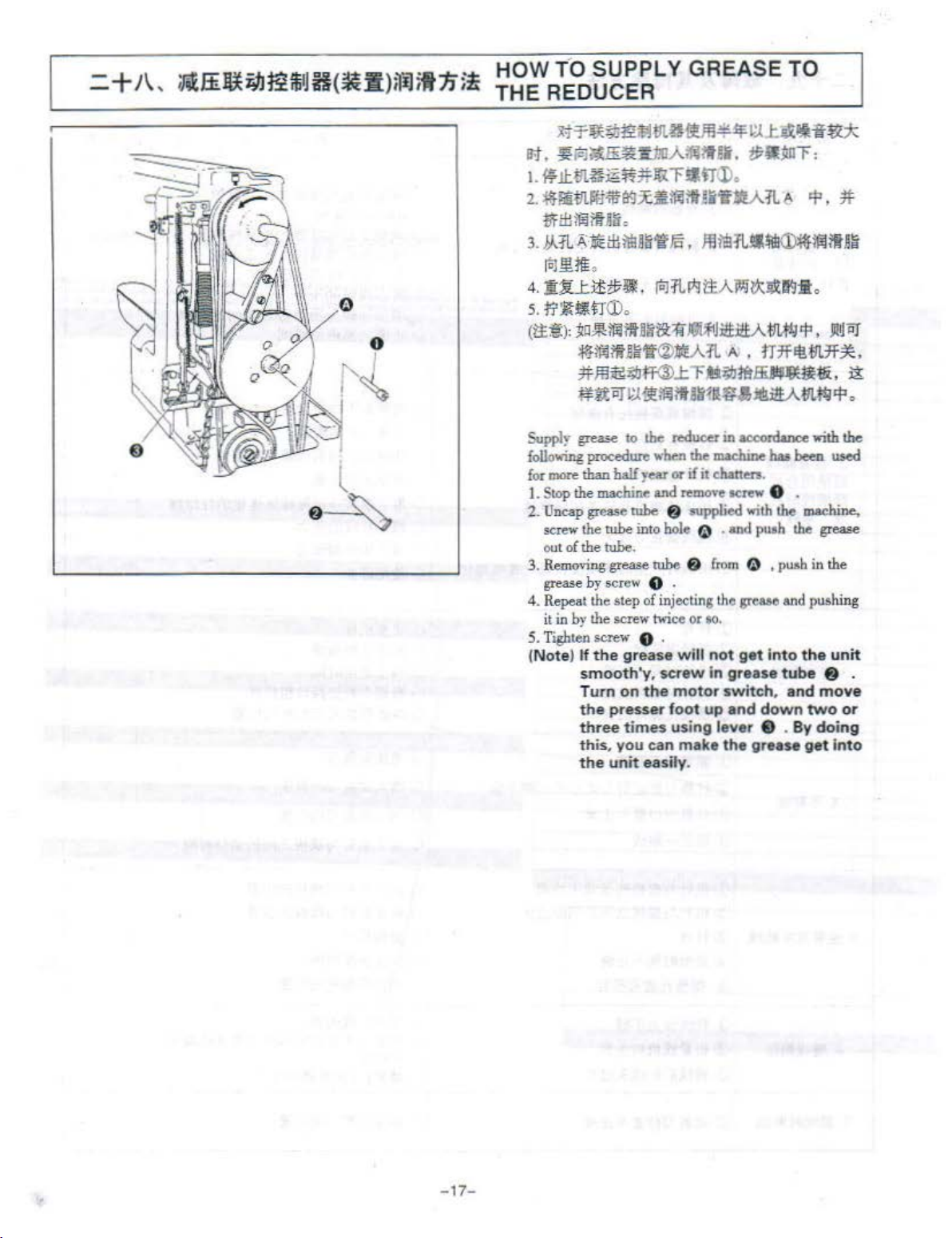
= +
J\,
ir.tEii~i'JJ~ffi
iJH(
!aii
)~iJi
tn;~
HOW T-0 SUPPLY GREASE TO
THE
REDUCER
M~~~~~ill.3~~~~L~~~~
~.~A~~~A~~G.~~~:
I.
.W.Itill~~~~~~-frl)
2.
~iiiill.Jit'lifa<Jxlljfijm!i'iflltA-11.~
~'HI:!
jfij
?ff!ir
o
L~UL
4.1:Ui!~lJ!
5.
(tt:§:):
~ii€1l:li'I!!B~'&'f<f.
toll!l.
M.
.
lol:rl~tl:AilJJ~~IfJ
lT~
~tr
(D.
~a~lfilit!liil1i
:tl}lfili!:Uii'lf(i)j!EA:rl A • rr7fil!*!L7f-*.
*~~~
~gtor~·.tliijma~r~~ajtgiitAM<P.
~Lr•~~~-
.
<P.
*
J!lti!!.JIJI~~iiilllt!
:fil:
JQi~JitH£A
~9',
li
.
Jl!~i'iJ
~~~.~
Supply
follo,.;,g procedure
for
1.
2..
3.
4. Repeat the
grea:-e
o:nore
Stop
the
Uncap grea.•e rube 8 •upplied
screw
out of the rube.
Removing
grease
it in
by
to
the reducer
wben
than
half
yeor
m.oclllne
the
rube
by
screw 0 .
Ule screw twice
in
grease
step
and
to
rube & from
of
injecting tho
the
or
if
remove
hole ~ • and
or
5. Tighten screw 0 .
(Note)
If
the
grease
smooth'y,
Turn
on
the
the
presser
three
times
this
. you can make
the
unit easily.
will
screw
motor
foot up and down
using lever 0 .
in
maclune
it
ehanen.
ocnw
so.
not gat
in
grease
switch,
the
acconlance
baa been
0 .
with
the
pu•h
the
~
,
p.ab
grea&e
and
into
tube
and
By
grease
with
the
used
m.oclllne,
grease
in
the
pushing
the
unit
8 .
move
two
or
doing
get
into
-17-
Page 20
$.
r.J
<lHHiletQ~
1.
mu
r!:i!i
B;f.tt~.Y-
mtt..t.Mltl:l
iZl
®
@
a>
~
2.~#~
~U{l-~
~!ti&B;f1L
!il(,~i;t
<3>
@
@ tJt!'lJf*:t.lif:k
~
~
::§
I
0
i.llf
0.05-{).1
o
J¥!!U
~·~~
li
:em
tt
J:l'l1l~
~;t;~!ki:m
~B;fli]~
iEiil
~~~:jHf~ll
::Jd:J:
liii
i.llm
o
lt:tm~
1]' I
o
llitiN!l~B9
o
it
0
iE
0
~;Kl!kT#Jil~
(
#i&1fi'Jj1j
-lll.ttaDf
~li!<I*!I
ffi-lll.#F~~N~~~~~M~
.!
IH
'r
~$
~tf!t~
O
J!ltk&:2<~:l!JM~
O
iii~U
o
.llltr
0
~Jj\#i;t~*:t.l
0
~~
o U
JJj
111'111<1f~
;HIUt~
.
..\lj
U
.Zi'BJ
t!IJ
liJ
It
~
*
2
~
1Elilffil9.J1ajtfiietoo
t-laH¥*1'l1l*.:IJ~tl'!'it
~
.ffi~fil'l1J.ffi.:IJ
£E}J
:tm
tt-lR
..!lj
life
T-J~
f6l~W
:i1t
!$
n
B;f
lliJ
M~~~
zlil
~
oo
lt
~
fl
<'fi)2<J4!11!{
~#lfi'li$ii'!~~
-
1*11
lit
ra
.IB.&9
~M£!1t
~
#~
$ -
tMttil!f
3.~#lt'f!'£
® iiHit
®:tll.
@
bf!:Qfl111l#
<D
~~W
<2>
4-~~~
5.~-nt~~d
6.
~laJ.fr
#t!i
<3l
;fJ
®
:liiFc-
<D
:til.#
<2>
mtt
®
#~
®
itti*II".JI'Iil:il'iE<,I€
®
~
<D
#~*
~
tk
®
~~Fcml~li*
B;f
fiil:il'iE
TI.I
#Xf;:f)if4::t.!JH
JJ~~
..!lj
!!!~
~
J]
99#
.lj!-[ii]~~&g
J1
JJU~iE!Ii
m~
..!lj~~&9
~
;b~t:J,ill
.!3DzliJ&91'1ilr;!tii::k
~~tim#
.:11
~
llt
~~
:tn.-lil~
0
}!l!k¥1.#
0
~iEB!.a$fa
0
*qiE
o
U<'li#
o
tJi
iEi~'t
o
J!~~nn
0
J:tl:!cZ.
Ot:l
iEi'JJ.#t
o ~
.u:
tnJt
O
tlliE:tll.#.!iiO~
tJiiE:!Q#
0
0
E.~-iM
:i:
Jtt~B;f
(lij
:ll!~~~~:tn.#
!H
t..\lj.Jn#l'l1lrul
~
JJ
&9"!f
JJ
~{JIR
l:Jl'J~z
~
Jit!lii'Jt!ri
t
[ii]
l'l1l
.iiiJbat[ii]
o isliEimietl'lil
0
ill
iEii.~~t!IJ«!
o
tthc#~~*.:h
0
~I:
-T :a:trttlti'Bl 2
~tk~
0
jf1JD
I~
ffi~ft(l9Bi;h
I
-i}
IE~
l\11
J!-
0
7.J:]ltl!;f~
(IJ i!fl}g
JJ
tiz
.l':
~ iE
lilt
- 1
8-
tJiiEi!!J
~
JJ!lg~
Page 21

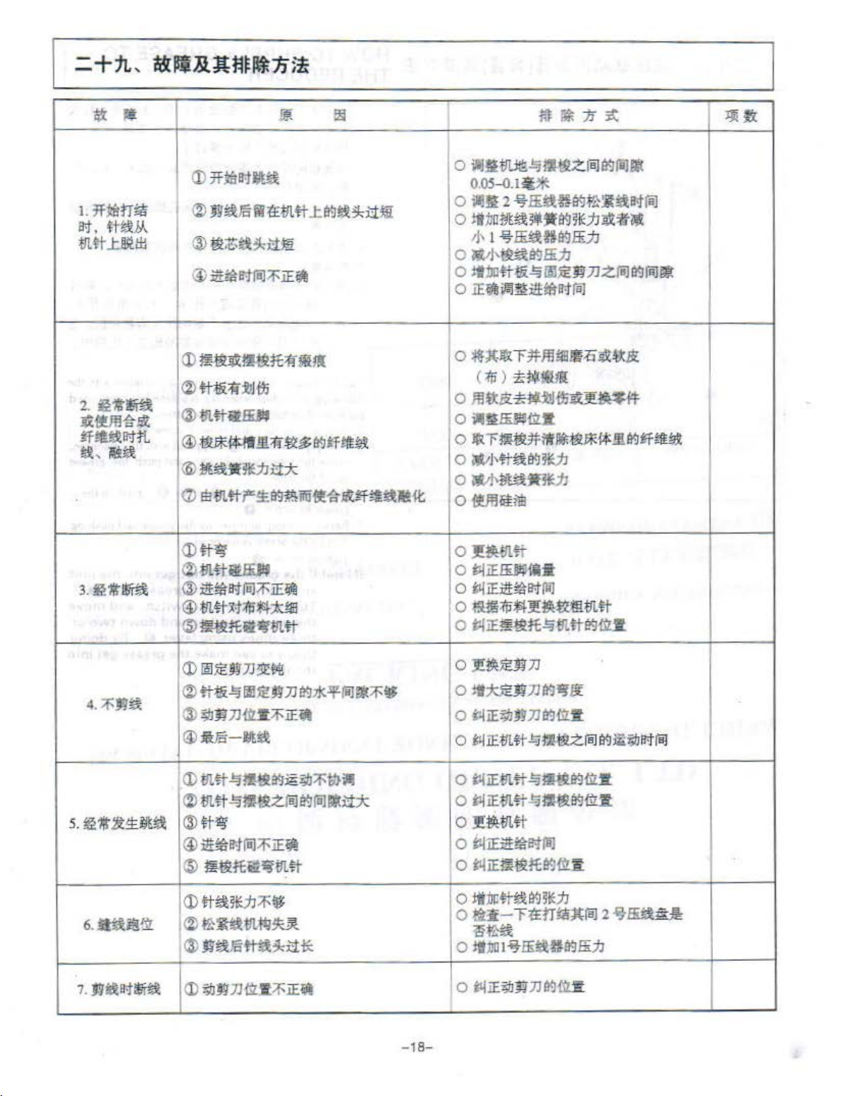
TROUBLES AND CORRECTIVE
Trouble
l.
The needle thread
slips
off
the
at the start
tackin
2.
Thrud
bareala
fiber
fmely
3.
The needle often
breaks.
4.
Threads
trimmed.
S.
Stitch skipping
often
6. The needle
comes out
wrong
inaterial.
g.
often
or
thread
.
occurs.
side
of
synthetic
ase
on
<D
Stitches are slapped at the stan.
(2)
The needle thread remaining
thread
needle
bar-
split.o
not
thread
the
of
the
after
@The bob
@ The feed rimming is bad.
<D
The shuttle
<%>
The needle bole guide haa scratches.
®The
@
Fil>rom
race.
<5>
The needle thread tension is
@The
too high.
CD
The synthetic fiber thread melu due 10 bea
generated on the needle.
<D
The needle is bent.
<2)
The needle hits the
@ The
@>
The needle is t
(5)
The
g?
The counter knife is
(2)
The difference
hole guide and the counter
@The
positiooed.
<i>
The last •titeh
(.1)
The
properly synchronized.
(2)
The clearance
is
@ The needle is bent.
® The
I@ The driver excessi,·elv ben
Q)
The needle
®
n,.
properl
@The
long.
bin
needle strikes the"'"!.: clamp
dust
tension
feed
driv
er excessivelv bends
~
motion!
too
large.
feed
tension
y.
needle
Cause
trimming
thread is
or
is
of
timing is bad.
of
timing is bad.
thread
release
thread
is
too
the drivdr hsa scratches.
in
the
groove
the
thread
work
oo
thin
for the material.
duU.
in
level
bas
lcinfe
is
•kipped.
the
needle and ahuule an:
between
tension
mechani
after
l'v4EA
on
the
too
short.
ohort.
foot
of
the shuttle
too
hith.
take-up spring u
clamp
foot.
tho
needle.
between
knife
the needle
i1
thread
is
been
ds the n
not
high
sm fails
trimming
the needle
not
improperly
and
oodle.
enough.
to
SURES
0
needle
0
0
0
0 In crease the clearance
0 Correct the
0 Take
0
.
0 Correct the position of the
0 Take out
0 Reduce the needle
0 Reduce the tension.
0
0 re
0 correct the
0
0 replace it
0
0 replace the counter knife.
0
.I.
0 conect the position
0 correcr the
not
0
ehullt
0
0
0
0
0 Increase
work
0
is
too
0 Increase the tension of the tension
Corrective
Adjust
the clearance
and lhe shuttle 10 0.05 to
Cotte<>t
of
lncrea.~e
spring
tension
Dec
hole
fine whetstone or
dust
the thread
the thead tension
the tension of the thread take-up
or decrease the tens
continue roller
rease the tension
guide and the counter
feed
it out and
Buff
or
replac;e
rhe
shuttle
from
the shuttle
measures
between
tension
controUer
of
rimmin
remove
buff~
it
.
and
n><:e.
No.1
thread
Use
silicone oil.
plar-e
the
bent needle 9
pos
ition
of
the
Correct
the material.
cotte<>tly
increase
shuttle.
Correct
Correct
Replace the bent needle.
Correct
C<>rrectly
Check
released during
coruroUer No.1.
the
feed
timing.
with
a thicker needle according
position the needle
the bend
the
the
the
position the driver.
the
whether or
of
the counter
of
tirnin&
be<Ween
positions
positions
bent
of
of
timing.
needle thread tension.
not the tension disc
.bar-t.aclci~
the
the
the
the
needle
0.1
mm.
release timing
Ko.2
.
ion
of
the thread
the
bobbin
thread.
between
g.
the scratches using a
the needle
knife.
work
elsmp
remcl\-e
tension.
work
clamp
and
moving
the needle
needle and
needle
foot.
the
fibrouo
foot.
the ahuttle.
knife.
i<nif
&.
and
ahuttle.
and
shuttle.
No.2
to
th
is
P
age
13
10
10
10
14
12
IS
13
10
11
7
IS
12
8
13
14
14
14
13
13
13
9
12
13
10
10
10
7.
Threads
time
trimming.
of
bresl:
thread
at
CD
The
PQ$itioned.
mo'ing
lcinfe
has
been improperly
- 1
0 Correct the position of
9-
the
mo•ing knife.
14
Page 22

Tacking Industrial Sewing Machine
~
PARTS
14
§
~
LIST
- 20-
Page 23

~
~
CONT
fir-It~
1.
~Jl!ileif~i!f
SEWING MACHINE COMPONENTS
2 .
..l:$~'a1Wf··
MAIN SHAFT·COMPONENTS
3.
~tfflllli!f·
NEEDLE BAR COMPONENTS
4.
t3tl'alWI:·
THREAN TENSlON RELEASE COMPONENTS
5.
1'$!11$i!f·
SHUTTLE DRIVER SHAFT COMPONENTS
6.
i!~f!ll:$t·
FEED MECHANISM COMPONENTS
7.
jl~fllli!f··
THREAM TRIMMING COMPONENTS
8.
l&\ili:Jt!t$111ill:$t···
~f*
!§!
~$7t
.............................................................................. .................... ·22
........................................................................................ , ........
.................................................................................................
· · .. · · ·
..
· · · · · .... · · · · ..... · .. ·
.................................................................................................
............................................... · ................................................... ·42
...
................................ , ................................. · ............................ 46
..
··
.............. , ........................................................................
.. · ..
ENT
· · · ·
..
· · · ·
S
..
· · .. · .. · .. · .... · · · · .. · · .... · · .... · · · ·
..
· · ...... · ·
26
·30
·34
·38
··48
PEDAL PRSSURE DECREASING
9. gili:JiJ$$:$t··
STOP-MOTION MECHANISM COMPONENTS
10.
iiilitt$~··
LUBRICATION MECHANISM COMPONENTS
11
.
m~~t&-
TABLE COMPONENT
12.
tl~f!ll~
THREAM TRJMMIG COMPONENTS
..
· .......................................................................................
................................................. _ ..................................... - ....
.=:Mt&ftili:Jf!ll~
........................................................................
.................................................
UNT
COMPONENTS
....
............................................ ·62
..
52
56
s8
-21-
Page 24

'
til.~
fll~
SEWING MACHINE COMPONENTS
l
@~
37
-22-
Page 25

.
REF
No
,!:f
"%
I
1
2
3
4
5
6
8
10
11
12
14
15 90-01- 015
17
18
19
20
21
22
23 90 -
2.4
25
26
27
28
29
30
31
32
33
34 90-01-034
35 99 -01-035
36
37
39
40 90-01- 040
41
42 90- 01-042
43 '90-01-043
44 90-01- 044
45 90-01-045
46 90-01- 046
47 90-01- 047
48 90-01- 048
49 90- 01-049
50
51
52
PART·
f!:j:
90-0190-01-002
90- 01-003
90-01- 004
90-01-005
90-01- 006
90-01
90-
·01- 010
90-0190-01-012
90-01-0
90-01-017
90-01- 018
90-0~..019
90-01-020
90- 01-021
90-01- 022
90-01-024.
90- 01-025
90-01-026
90- 01-027
90-01-028
90- 01-029
90- 01- 030
90- 01-031
90- 01-032 tjrj
90- 0l - 033
90- 01-036
90-01-037
90-01-- 039
90-01-041'
90-01-050
90-01 90-01-052
NO
0
..,
001
- 008
011
14
01-023
051
DESCRIPTION Q'TY
.;3
I
iii~.&
iliit&m
~.m
!.UT
ml!l
:£1l\ll
lli.
.till.
iill~t!f
~nr
~;;;$~
~ff
t.iliff~tr•
~ff
S,j!-!l;
tp~1;)
~-a;
~fi1;)
l:!~~
!!tn
~iii~~
!ltff
.tli~t&
!ltff
~-a;
.
~jj<fi
~ff
il.Ollrfi:
~~~
mll'!l
~~Iii!
!J.ff
:t:i~lli.
~jjl:f.&
Wi~~
:<Eftr~
l!l:<E~!ll:fll:
~ff
ill!*
SifT
f.t~m
~lillf.tilll~
~lT
~m~m
!i!Jii!l
m~
:s<~~!ll:fll:
FACE PLATE
FACE
PACKI
SCREW 11/
HINGE SCREW D=6.35 H=4.7 2
WAVED WASHER 6.4 x
BED COVER B 1
TOP COVER
BELT
COVER
SCREW
BELT.
COVEF.!
SCREW 9/
THR!;:AD TAKE-UP LEVER OIL GAURD
SCREW 11/
NUT 9/64- 40
THREAD GUIDE
NUT 9/64- 40
l - SHAPED THREAD GUIDE A 1
ARM THREAD GUI
SCREW 9/64-40 L=6 1
BED FITIING HOOK
SCREW 11/64-
THREAD GUIDE PLATE
SCREW 15/
NUT 15/64-28
FIRST THREAD GUI
SCREW 15/64:-28 L=8
RUBBER WASHER 2
SPR
ING PIN 8 x 20 2
BASE
CONNEVTING PIN 2
WASHER 10.5.x.18 x 2 1
E- RING 6
SCREW 15 /64- 28 L=11
BEDCOVER'A
ST
AY
BED
ROCKER 1
STAY
ROCKER
STAY GUI
· HINGE SCREW 0=8 H=3.4
THR
EAD
SCREW 15/
VIBRATION-PROOF RUBBER 2
RUBBER BUSH 2
SCREW
WASHER 4.5 x 10 x 0.8
RUBBER
BED
FITIING
SAFETY PLATE ASM.
f*
ASM
.
NG
6<\
- 40 L=10 2
11
x 0.3 2
FIXING PAL TE
11/
64~40
64-40
64-40
64-28
DE
TENSION
64-28 L=1
RING
L:8
L:7
L=7.8 1
DE
A
40
L=8.3 2
L=7 1
DE
..
ASM.
SPRING
2
.BASE
·
li.
1
1
1
1
2
1
2
1
1
1
1
1
1
1
1
1
2
1
2
1
1
1
1
2
1
2
1
1
1
1
1
-
23-
Page 26

' «fe8f4:
SEWING
MACHINE
COMPONENTS
·
12·13
-24-
,
..
_
__
,..
__ __
,
Page 27

REF
No
"-it
53
54
55
56
57
58
59
60
61
62
63
64
65
66 90-
67
68
69
70
71
72
73
74
I
PART
90-01-053
90-01-.054
90909090-01-058
90-01-059
90-01-060
90-01-061
90-01--062
90-01--063
9090-01-065
9Q-01-067
90-01-068
90-01-069
90-01-070
90-01--071
90-01-072
90--01-073
90-01
..,
~
01-055
01-056
01-057
01-064
01-066
-074
NO
c
DESCRIPTION
~
$:~~
i«tr
ml!l
t~mm
lij
jt
~~
~~{&~
iltr
m
SAFETY PLATE
SCREW 11/
WASHER 4.5X10X0.8
HINGE SCREW
SPRINGER
WASHER
SAFETY PLATE INSTALLING PLATE 1
SCREW 11/64SPRING PIN 2 x 6 1
>lfl SCREW
~~a~
!tt!l:
!IJBl:
SAFETY PLATE INSTALLING BASE
NUT 11/64NUT 3116-28 1
rm SCREW
SifT
!!ttl
'Ftt1;J
!lm!l
~LUi
JJ!~~~t&
mil
;t.lil
ll
SCREW 15/64
SPRING RACK 1
ARM THREAD GUIDE B 1
HINGE SCREW
RUBBER PLUG 1
SPRING 2
WASHER 2
RUBBER PLUG 1
jij:
64-40
11/64-40
11/64
L=7 2
0=6
.H=0.2
40
L=7
L=7 2
40
- 40 L=7 2
-28
L=11
.5
0:8
H:6
.8
Q'
tt
TY
•
1
2
1
1
1
1
1
1
5
2
I
-25
-
.
Page 28

_ ,
..ttlkill~
MAIN
SHAFT COMPONENTS
-'1
/ I
- I
I
)
-26-
Page 29

REF
..
1
2
3
10
11
12
13
14
15
16
17
18
19
~
21
22
23
24
25
26
27
28
29
30
31
32
33
34
35
36
37
38
39
40
41
42
43
44
45
46
~
4
5
6
7
8
9
No
PART
90-02-001
90-02-00
90-02-003
9o:.:~z::'oo·
90-02
90-02-006
~02-007
90-02-008
90-02-009
90-02-Q10
90-02-011
90-02-Q12
90-Q2-013
90-02-Q14
90-02-Q15
90-02-Q16
90-02-Q1
90-02-Q18
90-02-Q
90-Q2-Q20
90-02-Q21
90-02-Q22
90-02-023
90-02-024
'90--02-025
90-02-Q26
90-02-Q27
90-02-Q28
90-0?-Q29
90-02-030
90.02-Q31
90
90-02-033
90-02-034
90-02-Q35
90-02-306
90-02-Q37
.
90-02-QlS
90-02-Q39
90-02-040
90-02-041
90-02-042
90-02-043
90-02-Q44
90-02-045
90-02-Q46
NO
c
..,.
f4:
2
'
f
:..
005
7
19
~02-Q32
\tlft1~Jt
!ItT
!ItT
jfUf
!ItT
ttffllliii
l:.$ilifi*
l:.$111
l:.$\i<P~
Mff
!ItT
ffllll
!ItT
$iliiM89102
$11i*KS151917
l:.$\1.6ff
!ItT
J'ltlCI~
!ItT
•n
!ItT
•n
!lltl
ltii!CI~l:llf4:
ltii'LCI
Jl:~ti
••
m
ili-a-Ill
•n
•m
~111(1)\)
~Ill
•i!'&:m~
$111~107
\lll>!AIII SHIM
!All(:*)
nlll
IIfii~
n!ll
$ti!!lm~l:llf4:
•n
~il&:m~
ttilll*~'*
•n
•-a-•
~
W
DESCRI
NEEDLE ROO CRANK WASHER 1
SCREW 15164-28 L=14
SCREW
SCREW 9/32- 28
SCREW 1/4-40
COUNTER WEIGHT
UPPER SHAFT FRONT METAL 1
MAIN SHAFT
UPPER SHAFT INNER METAL 1
WORKASM
SCREW 11/
THRUST
SCREW 11
UPPER SHAFT THRUST BEARING 2
MAIN SHAFT
UPPER SHAFT REAR METAL 1
SETSCREW
THREAD CUTTING CUM ASM. 1
SCREW
SCREW 1
SCREW 15164-26 L=12
SCREW 318-28 L=14.5 1
-SCREW 318-28
STOPSTOP-MOTION
STOP-MOnON
SAFETY PLATE STOPPER SPRING 1
PIN 1
HIGH SPEED CLUTCH PLATE ASM. 1
SCREW 11164-40 L=8
SCREW 11/64-40
SPACER 3
SPRING 2
HIGH SPEED PULLEY 1
BEARING
WASHER 2
RETAINING RING 32.2
.
SLOW SPEED PULLEY SPRING
RETAINING RING 66.2 2
PULLEY ASM.
SCREW
PU
LLE
PULLEY SHAFT 1
SCREW 1/
SLOW
PTION
¥$
s
1/4-40
MOnON
11/64-40
Y
SPEED PULLEY SHAFT
L=4.5
L:16.5
L=6
. 1
64-40
L=14
COLLAR
4-40
D--35
4-40
ASM
. D=15 W=10.8 1
L= 1
1·
NEEDLE BEARING B 1
L:19
.5
CAM ASM. 1
CAM 1
CAM LATCH
.5
L=5.5 1
x
62
L=5.5 3
L=6
O'TY
••
1
1
1
1
1·
1
4
2
1
1
1
1
1 .
2
~
4-6
3
1
1
1
1
·- 27-
Page 30

_ ,
JJ
tUllff
MAIN
SHAFT
COMPONENTS
18
'
'
. .
.
36
40
35
37
/ 64
(
~;
~ 1>
~
48
/.
,/
·
3
~-...-·1
•
I.
'
)
48
/'
-
28-
Page 31

RE
F No PART
1
ff~
47
48
49 9
50 90- 02-050
51
52
53
54
'1:
90-02- 047
90-02
0-02
90- 0290-02- 052
90-02
90
- 02-054
NO
0
"'
i:ltr
- 048
- 049 I!!
051
- 053
f!.t
~li!l
~
\lil
iltr
~'*
ill!
Bi:
~ ~
.g.~
tr
J:l<~
DESCR
SCREW 1i4-40 l = 11 1
SLOW SPEED PULLEY
SLOW SP
SPRI
NG
SCREW 2
BALL RETAINER
SCREW 9/64-40 L=7.2 2
STOP-HOTI
IPTION
:g
~
EED
PULLEY PLATE 1
WASHER 4.5 x 8.5 x 1
ON
BALL 1
-
Q'TY
·ij& .
1
2
1
-29-
Page 32

_ ,
tHl!Bi!f
NEEDLE BAR CO
MPONENTS
13
20
16
'
.J
~
17
;·----
·'
•
•
•
•
•
I
I
----
-30-
Page 33

REF
No
"'~
30
31
32
33
34
35
36
37
38
39
40
41
42
43
44
45
46
47
48
I
1
2
3
4
5
6
7
8
9
10
11
12
13
14
15
16
17
20
21
22
23
24
25
26
27
28
29
PART
90-03-001
90-03-002
909()..03-004
90-03-005
90-03
90-03-007
90-03-008
90-03-009
90-03-010
90-03-01
90-03-012
90-03-013
90-03-014
90-03-0
90-
90-03-017
90-03-020
90-03-021
90-03-022
90-03-023
.90-
90-03-025
9()..03-026
90-03-027
90-03-028
90-03-029
90-03-030
90
90-03-032
90-03-033
90-03-034
90-03-035
90-03-036
90-03-037
90-03-038
90-03-039
90-03-040
90-03-041
90-03-042
90-03-043
90-03-044
90-03-045
90-03-046
90-03-047
90-03-048
1*
03-003
03-016
03-024
-03-0
NO
0
~
-006
31
1
15
DESCRIPTION
liE
tiiff
:};J§
i4:
liEtiii!:f'HII
1.eaoum
ftffi!ff
~'iUt1\a
!ti!lliitili
liEE!ff!!H
CfT
Uff,l!tlif.&
CfT
!Iff
.f'Jtiili
jJ{i
jJff$t!J HI
t:llll
!IIlli
~KS0811
iilU~~KS081208
tf
jjlfT
ttff
..l:~fi;i
ttfflilitt
ttff
ttff"F1flilf
jJfT
~JUt
ftff~~
~tl!!li!J!itf
!ill!~
~tiiit~
~HU!
~ttitlf
tl!tiiB!!!f*
lf
LINK BALANCE ASM. 1
BALANCE CRANK PIN
LEFT SCREW 1
NEEDLE BAR CRANK
10 NEEDLE DRIVING LEVER BEARING C 1
NEEDLE BOD CRANK 1
NEEDLE BEARING
BALANCE
SCREW 15/64-28 L= 1 1 1
NEEDLE
NEEDLE
SCREW 91
NEEDLE BAR 1
NEEDLE ROD LOWER HETAL
SCREW 3132-56 L=4.5
NEEDLE BAR THREAD GUI
NEEDLE
SCREW 1/
SQUARE BLOCK
SCREW
THREAD GUIDE BRACKET ASM. 1
NUT 11/64-40 1
TH
READ
BOBBIN WINDER TENSION POST 1
BOBBIN WINDER TENSION DISC 2
BOBBIN WINDER TENSION SPRING
BOBBIN WINDER TENSION NUT 1
BOBBIN WINDER ASM. 1
NGE
NUTM6
NUT 11164-40
~
-8
ROO
ASM.
ROD
HETAL
ROD
HOLDER ASM.
64-40
DP
8-44
15164
GUIDE BRACKET 1
SCREW D=7.94 H=13.3 1
L=6 1
DE
x 5
#14
L=2.9 1
-28
L:9
O'
tl
JltT SCREW 1 1164-40 L=5
~ll:..Elifi
!l!ttll:.~ff
tl!tii~
il!tcUlll~
!Iff
tUt~f.&
jJff
BOBB.IN
BOBBIN WINDER BRAKE 1
BOBB
BOBBIN WINDER SPINDLE BUSHING
SCREW
BOBBIN WINDER BELT SUPPORT
SCREW 111
WINDEFI
IN
WIND
11164
.BRAKE PRESSURE P
ER WHEEL 1
-40 L=5
64-40
L=7.8 1
IIUlfTftli BOBBIN WINDER TRIP LATCH 1
t\\tl$lli
jJlJI
~-
~m
!l!t&tJI:iEf&
tifT
BOBBIN WINDER SHAFT 1
BUT 1/
SPRING 1
HINGE SCREW 0=7.24 H•1.9 1
BOBBIN
BOBBIN
4-40
WIND
WIND
ER BASE 1
ER ADJUSTING SCREW 1
TY
i
1
1
1
1
1
1
1
1
1
1
2
1
1
1
1
1
1
1
1
1
-31-
Page 34

_ ,
tHfi~i!f
NEE
.DLE BAR
16 'J
20
COM
PONE
;---
0
0
0
1
1
NTS
- 0
0
0
0
~
1
7
'
0
51-f
:
0
0
0
0
0
'
/
/
--
.-
0
0
0
I
0
1
1
-3
2-
Page 35

REF
No
l'f~
49
50
51
52
53
54
55
56
57
58
59
60
61
62
63
64
65
66
67
PART
90-03
90-03-050
9090-03
90-03-053
9090-03- 055
90-03
90-03- 057 itt§ NEEDLE PLATE
9090-03
90-03-060
90-
90
9090-03-064
90-03-065
9090-
1/f
~
-04
03-051
- 052'
03-054
- 056
03-058
-05
03-06
:;-03-0
03-063
03-066
03-067
NO
9
9
62
1
DESCRIPTION
~
;Ai:Uit:t§
!llff
ilfT
itt§~¥!=
;;i.JJJ
!!Iff
'Ht:t§
!llff
~JJ
!\Iff
;;i.JJJi!*t
;;I.JJJ*ftl!lt-1
;;I.JJJI!Il~
~
;;/.JJJft;;i.J*t
!!Iff
YHil
!llff
V!J!'it.'!lil
BOBBIN WINDER
SCREW 11/
SCREW 111
NEEDLE
MOVING KNI
HINGE SCREW
NEEDLE HOLE GUID 1
SCREW
FIXING KNI
SCREW 9/
MOVING
THREAD CUTI
THREAD CUTI
THREAD CUTTER LEVER ASM., LARG 1
SCREW 1
WASHER
SCREW 11/64-40 l=7
NG
MOVI
f;'F
64-40
64-40
PLA
TE ASM. 1
FE
3132
-56
FE
64-4
KNI
FE
1164
KNIFE WASHER C 1
Q'
TY
~ ·
TRIP
LATCH 1
L=9
L=5.5 4
ASM.
D=S
.O H=0.
L=2.2
ASM.
0 L';3.5
LINK 1
ING LEVER RING
ING
LEVER , SMALL 1
-40 L=4.0 1
9 1
2
1
2
1
1
2
1
1
1
-
-33-
Page 36

ll!L
t3
iUU
i*
THREAD TENSION RELEASE
COMPONENTS
-34-
Page 37

REF
No
"~
1
2
3
4
5
6
7
8
9
10
11
12
13
14
15
16
17
18
19
20
21
22
23
24
25
26
27
28
29
30
31
32
33
34
35
36
37
38
39
40
41
42
43
44
45
46
PART
90-049().-04-
90-04-003
90-04-004
90-04-005
90-04-006
9o-04-007
90-04-008
i'l=
NO
c>
..,.
001
002
90-04-009
90-04-010
90-04-011
90-04-012
90-04
- 0
13
90-04-014
90-04-015
90-04-016
90-04-017
90-04-018
90-04-019
.
90-o4-020
90-04-021
90-0
4-022
90-04-0
9().-0
90-04-025
90-04-026
90-04-027
90-04-028
90-04-029
90-0
90-04-03
. 9().-04-032
90-04-033
90-04-034
90-04-035
23
4-024
4-030
90-04-036
90-04-037
90-04-038
9
0-04-039
90-04-040
90-0
4-041
90-04-042
90-04-043
90-04-044
90-04-045
90-04-046
O'
lU
TY
l
1
1
1
1
1
1
2
1
1
1
1
1
2
1
1
1
1
1
1
1
1
2
1
1
1
1
1
1
DESCRIPTION
fj:
s
~tifl
!lfl
l3ti;ff~f!!:
~t!H~f!f
~iT
~tiS~
!ItT
ilti
iit
~tit&
~lit&
~
fi-~
~fi
-
~fi~l;;IJ1&
~fiji~
,
,,~!i~i'l=
iltT
~lift&
~iii
eM
illl"P
ii-Bi
!ItT
f<}lifiUf
f<}fi!L
fil
;;IJt&
ilfl
!l-Ilt
~lii~tf
tifT
~t!
ii<lf
~iT
f<}f:i
t!ff~
MitT
1
f.}
!iff
fatit
;ff
~~
!ItT
est
~fi
ft;;l)t&tll:l*
!ItT
faf!
fti';l)l&iiff
~1!1
ilfJ
tt
Jt
liti!l
ilfJ
t3
!ii.lil'P
iUf
!Ill
!Ill
l3fi~'j;;ff
TENSION RELEASE
SCREW 15i64
WIPERASM.
SECOND THREAD TENSION ASM. 1
SCREW 9/64
THREAD TENSION ROO. LARGE 1
SECOND THREAD TENSION
THREAD TAKE-UP SPRING
THREAD TENSION DISK
THREAD TENSION DISK PRESSER
THREAD TENSION DISK PRESSER
THREAD TENSION SPRING 1
ROTATING STOPPER
THREAD TENSION NUT 1
FIRST THREAD TENSION ASM. 1
THREAD TENSION
THREAD TENSION DISK 2
FIRST THREAD TENSION SPRING 1
THREAD TENSION NUT
HINGE SCREW
CONNECTING LINK 1
LOWERING FOOT 1
HINGE SCREW
NUT 1
5164
LOWERING ARM 1
SCREW M6 L=18
TENSION RELEASE ARM
SCREW
SHAFT
HINGE SCREW
TE
NSION RELEASE BA R
THREAD TENSION ARM 1
SCREW 9/64-40 L=
NUT 15/64-28
LOWERING CONNECTING LEVER ASM. 1
HINGE SCREW
LOWERING CONNECTING RING 1
C- AING 1
HINGE SCREW D=7.24 H=3.3 1
TE
NSI
ON
SPRING PACK 1
HINGE SCREW
CONNECTING ARM
SCREW M6
HINGE SCREW
WIPER CONN
-28
-40
-28
M6
L=18
SPRING 1
L:18
PIN
L=17
L=5
.9
ROO
ROO
0=10
H=4
0:7.94
0=5.3
l>--9
0:6
0:5.3
ECn
H:6
H=2.2
6.1
H=3
.2
.35 H=3.9 1
H=2
.2
NG LINK
-
35
-
Page 38

ll!L
t3
~
mi
i4
THREAD
TENSION
RELEASE
COMPONENTS
15
)'"
: '
I
15
..
46
-
36-
Page 39

REF No PART NO DESCRIPTION
#;
ff~
~
.s
f*
Q'TY
tt
•
47
48
49
50
51
52
53
54
55
56
90-04-047
90-04-048
90-04-049
90-04-050
90-04-051
90..04-052
90-0~053
90-04-054.
90-04-055
90-04-056
tt:•
r.ltli!ti~!lli'l=
ffllll
•mtl
.IIi(
.
f-ltlbt~
fflll!l
f-ltl*Tfil:lE~
en
en
.
SPRING
WIPER
RETAINING
WIPER
OIL
WIPER
SNAP
WIPER
SCREW
HINGE
CONNECTING
CONNECTING
SHIELD CAP
CONNECTIN
RING
INSTALLING
11164-40
SCREW
RING
0=6.35
ARM
4.7
SCREW
G PLATE
PLATE
L~S
H=2
ASM
. 1
.1 1
1
2
1
1
1
1
1
1
.
-
37-
Page 40

1i
,
1'$1UU#
SHUTTLE DRIVER SHAFT C
12-
,
~~12
11~
1 I ,
I
8
OMPONENTS
20
19
2
~
d
----===::::::::::.
-38-
__
_ ·-
Page 41

REF
No
"~
1 90-05-001
2
3
4
5
6
7
8
9
10 90-05--010
11
12
13
14
15
16
17
18
19
20
21
22
23
24
25
26
27
28 90-05--028
29
30 90-05-030
31
32
PART
'*
90-05::-002
90-05-003
90-05-004
90
-0~005
90-05-006
90-05-007
90~
90-0S-009
90-05-011
90-05-012
90-05-013
90-05-014
90-05-015
90-05-016
90-05--017
90-05--018
90-05--019
90-05-020
90-05-021
9
0-05-022
90-
.05-023
90-05
90-05-025
90-05-026
90-05-027
90-05--029
90-05-
90-05-032
33 90-05-033
34
35
36
38
39
40
41
42
43
44
45
46
47
90-05-034
90-05--035
90-05--036
90-05--038
90-05-039
90-05
90-05-041
90-05- 042
90-05-043
90-05-044
90-05-045
90-05-046
90-05-047
NO DESCRIPTION O'TY
~ ~
~~~it
it
~
"'
fi•C.·
lt#l
l!#l}t
tm
it~1U~
l'ti!ll'iltt~~KS081110
~Iii
it~f*
~-'*
·
i:lfl
~n
it~~'Ptl!f
!lfl
fflllll
;sn
-024
031
-040
1'$111.61111
l'$1!!.6$.1i
"F$ili~it
:kil:lt!ftit
l!lfl
l!liltl!f
117JJi&
Uti;
r:ll!l
lilil
r:llll
SliT
t~illlt&~$11
lilt]'
fiiii<lr.ffit&
ftl!ii<t=i.ffit&
~
·
~
-tl!f
it.EI<
~
JIB
lilfT
~-'*
!JU
SifT
~~!§.it
!ita
~j(A
mliil
;su
.
·~
~
il
•m
~
~
INNER
INNER
SPRING
CYUNDEA
HOOK
SCREW
HOOK
SCREW
SCREW
WORM
WORM
HOOK
THRUST
SCREW 114-40 L=7 2
i'i
INNER
HOOK
PRESSER
BOBBIN
BOBBIN
I
NNER
DRIVERASM.
SCREW
SHI:JTTLE
NEEDLE
WAHSER
SHUTILE
SHUTTLE
SCREW
SCR
SHUTILE
SCREW 11/64 THRUST
SCREW
LOWER
LOWER
LOWER
CRANK
SCREW 11/64-40 L:10.5
HINGE
OSCILLATOR
NUT
THRUST
SCREW 11/64-40 L:4.5
THRUST
SCREW
OSCILLATING
SCREW 15164-28
INNER
CASE
ASM.
HOOK
3116-28
DRIVING
3/32-56
EW i S/64-28 L:11.5
COLLAR
1 1/
SHAFT
SHAFT
SHAFT
ROD
SCREW
1/4-40 1
COLLAR
COLLAR
-11/64-40 L:4.5 2
HOOK PRESSER, LEFT
HOOK PRESSER,
HOOK
PIN
COVER
1/64-40
COV
1/4-40
318-28
WHEEL
WHEEL
COVER
COLLAR
L:12.0 1
NEEDLE
9.5 X 14.8 X 2.6
UPPER
L:3
RACE
ADJUSTIN
40
64-<\0
REAR
THRUST
GEAR A ASM.
ASM
D:8 H
SHAFT
PRESSER,
2.5x
16
ARM
CAP
PRESSER
L=11
ER
PRESSER
L=11
L=19
ASM
SHAFT
PRESSER
ASM
.
OUTER
LEVER
SPRING
L=4.3
ASM
L:4.5 2
. 1
ASM
ASM
L:S
.5
.
ASM. 0:18
RING
BEARING
.5
G SHAFT
. D:B.O
METAL
s10.2
. 0:7.94
. 1
ASM.
BUSHING
W=8
WASHER
W=10
RIG
HT
SPRING
SPRING
SPRING
SPRING
W=12
B 1
PIN
A 1
tt •
B 3
2
2
2
1
1
1
1
2
1
1
1
1
1
1
1
1
1
1
2
1
1
1
1
1
1
1
1
1
t
'
1
1
1
1
1
1
1
-39-
Page 42

1i
,
""F
$Jk
~n
i4
SHUTTLE
DRIVER
SHAFT
COMPONENTS
-40
-
Page 43

REF
ff~
No
PART
'f!!:
NO
-It
D
ESCRIPTIO
~
N Q'
~
TY
112
.
48
49
50 90-<lS-050
51
52
90-05-048
90-05-049
90-<lS-<>51
90-<lS-<>52
Cflt
J.Ui
II¥$$
tl{ft
m~CJ~
NUT
1/4
WORM
CAM
NUT 9/16-20
FEED
WHEEL SHAFT
GUIDE
CAM
IN
ASM.
1
1
1
1
1
-41
-
.
Page 44

~
~~mH~
I \ '
FEED
MECHANISM
COMPONENTS
50
-42-
Page 45

REF No
I¥~
PART NO
14:
0
.,.
DESCRIPTION
;g
f#
Q'TY
J
Hi
1
2
3
4
5
6
7
8
9
10
11
12
13
14
15
16
17 90-0618
19
20
21
22
23
24
25
26
27
28
29
30
31
32
33
34
35
36
37
38
39
40
41
42
43
44
45
46
90-0S-001
90-06-002
90-06-003
90-06-004
90-06-005
90-06-00
90-06-007
90-06
90-0S-009
90-06-010
90-06
90-06
90-06
90-06-0
90-06-0
90-06
90-06-018
90-06
90-06-020
90-06-02
90-06-022
90-06
90-06-024
90-06-025
90-06-026
90-06
90-06-028
90-06-029
90-06-030
90-06-031
90-06-032
90-06-033
90-06-034
90-06-035
90-06-036
90-06-037
90-06-038
90-06- 039
90-06-040
90-06-04
90-06
90-06- 043
90-06-044
90-06-045
90-06-046
- 008
- 011
- 012
-013
14
15
- 016
017
- 019
-023
- 027
- 042
~tr
t~~
!UJ
ffiJI!IillHt.liM&!fi
tL~
6
ti:B!JI!IillHI-~
t£71-~~
~f-IJ.;
:;tiM.&
illtr
Wl
tl<(1/8')
WI
.£it~
!lltr
m!l
fir~~~f.t
i!*4~
.9J.tr
:t>mmmrr~
J!.!ltr
tj!>'f!!l
~tr
1
B!H.\llillit&
ti:B!JI!Ii
:G'B!JI!Ii
S!tr
ml!l
i!*4~
~m
mit&
i!*41t~
~~llfl:ff~
$jt'J
!!ItT
!ll;aJ:
m~
W.
ioJ
ilt~iJHt
tili
Si~
l!:ff
ill±~~
oo;;~
!l!iime
1
~:ffitf±~
!Iii! ill:
ti!J!!I
$t·Hll!
!ft
-1'
!:JI
,IoJJtt
~!lff
SCREW
E- RING 7
WAHSER
LEVER
it
T
ENSION
LIFTI
LIFTING LEVER
SUPPORT PLATE
SCR
WORK
BALL
SCREW
WASH
SPRING
FEED BRACKET 1
SCREW 15/64- 28 L=4.7 1
LIFTING
SC
FINGER
SCREW 11/64
WORK
WORK
WORK
SCREW
WASHER
FEED
SCREW 11/
FEED
FEED
FEED DR
SCREW
SCREW 5/16-24 L=10
NUT 15/64-28
WASHE
FEED REGULATOR
HINGE ST
NUT 5116-24
FEED REGULATOR STUD
INDIC
HI
NGE
SLIDE BLOCK B
NU
WASH
FEED
FEED
FE
11/64- 40 L
DRIVING
SPRI
NG LEVER,
EW 11/64-40 L=8.5
CLAMP
RETAINER
M6
L=20 1
ER
6.2 x
SUSPENSION 1
LEV
REW
1/8-44 L=2.8
GUARDE
CLAMP FOOT FACE
<;LAMP
ClAMP FOOT,
15/64-28 L=9.5
PLATE
64-40
PLATE PRESSER PLATE
PLA
TE CARRIER
IVING ARM SHAFT
15/64-
R7x
UD
ATOR LEVER
SCR
EW 0=5.3 H=2.2
T 1/4-40
ER
6.5 X 13 X 0.8
CAM
ROLL
CAM ROLL
ED DRIVING
=7
PLATE
NG
LEFT
SHAFT
FOOT H
13
ER,
RIGHT
-40
FOOT, RIGHT
28
15x2
ER
ER
ARM
ASM.
OUNTING
x 1 1
L=8.7 5
LEFT
L=4.8
BAR
L=11.5 1
SHA
FT
BASE
PLATE
~
4
2
2
2
2
1
1
1
2
7
1
1
2
1
1
1
1
1
1
1
5
1
1
2
1
2
1
1
1
1
2
2
2
2
2
2
2
2
1
-
43
-
Page 46

i2S~i~#
FEED MECHANISM COMPONENTS
-4
4-
Page 47

R
EF
IH·
47
48
49
50
51
52
53
No
PART
j:f
90-06-047
90-06-048
90-06-049
90-06-050
90-06-051
90-06-052
90-06-053
54 90-06-o54
55
56
57
58
59
90-06-055
90-Q6-056
90-06-057
90-06-osa
90-06-059
NO
c
..,.
DE
SCRIPTION
~
~fT
ltff$111
~Ill!*
¥it&
~n
~m
!l.\
81
iW~$11i
ift~
!lil.tT
tlioli!~il;IT
~ioli!~~
en
SCREW 15.64FEED REGULATOR SHAFT
RUBB
ER
PLUG 2
PLATE 1
SCREW 111
SCREW
WASHER 7 x
SUDE BLOCK STUD 1
SQUARE BLOCK 1
SCREW 15164-28 l =10.5
FEED ACROSS DRIVING ARM
FEED ACROSS REGULA TOR
SCREW 15164-28
15164-28l
~
28l=14
64-40
20
x 4.5
•
l=8.3
=1
1.5
l=
11.5 1
O'
l
TY
Ui
1
2
2
1
1
1
1
1
-45
-
Page 48

t,
-
JHl~Hf
THREAD
TRIMMING
COMPONENTS
19
12
23 ;
-
---
I
-J
0
•
-46-
Page 49

REF
No
ff:~
1
2
3
4
5
6
7
8 90- 07- 008
9 90- 07- 009
10
11
12
13
14 90- 07-014
15 90-07- 015
16 90-07- 016
17
18 90-07- 018
19 90- 07- 019
20 90 -07- 020
21
22
23
24 90 -07- 024
25
26
27
28 90-07- 028
29 90- 07- 029
30
31
32
33
34
35 90 -07- 035
36
37
38
39 90 -07-039
40 90-07- 040
41
42
PART
i'F
90-07
90-07-002
90-07
'
90-07-004
90- 07-005
90-07-006
90-07
90- 07- 010
90- 07-011
90-07
90- 07- 013
90-07-017
90-07-021
90-07
90- 07- 023
90-07
90-07-026
90- 07-027
90-07
90- 07-031
90-07
90-07-033
90- 07- 034
90-07-036
90- 07- 037
90- 07- 038
90-07-041
so
:..
o7- 042
NO
0
"5'
- 001
- 003
- 007
-012
- 022
- 025
- 030
- 032
DESCRIPTION
~
'*
:f.i:tl'!A
m~
~n
:f.i:ti1!B
~i&i!lit&ii!#
r:i~
s.m
m:lil
~i&iiiit&~
t31!!l
~~)Jft;;i)ff
!Ill~
~
.f.t
~mi1i
~n
liilViR.f!
lli!~fti1
lliii.u!l.#
~~~;;i).t!ff
l'i!ff~#
l'iiff
s.m
l'llff~#
Sli#
mtt
~l!il
t~l!il
mil
£itT
Sl!ma
~~~Siiiiff
SifT
~~~Sii~~
f;!jfm
~f;!<~Sii~~iiiit&
~fT
ttii
i!trl
~lit
~n
ml!l
tllii~Wi~~iiii~t&
TENSION
TENSION
HINGE
THREAD
THREAD
T
HREAD
SCRE\I/15/64-28
THREAD
THREAD
RETAINING RING 10.2
CONNECTING
NUT 3/16-28
ROLLER
HINGE
SCREW
THREAD
CAM
THREAD
COMMECTING
LOWERING LINK
LOWERING
HINGE
L
OWERING
NUT 1 5164-28
ROLLE
WASHER
STOP RING
WASHER
SCREW
HINGE SCR
AUXILIARY
SHAFT
THREAD TRIMMING AUXILIARY
RETAINING RING
CONNE
HI
NGE
SPRING
TNESION
N
UT 111
SCR
WASHER
CONNECTING
SPRING
SPRING
SCREW
CUTIING
CUTTING
ClJTTING RING
CUTIING
CUTTING
SCREW D=6
9/32-28 L=
ClJTTING
STUD
ClJTTING
LINK
SCREW
LEVER
R 1
9.8 x
3/8-28L=14.5
EW
LEVER
CTING
SCREW D=7.94
SPRING
64-40
EW
11164-40 L=S.S
4.8 x 8.4
RACK
8
D=6
.5 H=3 2
LINK
SPRING
LIN
K
L=14
LINK WASHER
LINK
ROD.
LARGE
SHAFT
RAC
.
.5 H=13
19
CAM
ROLLER
CAM
COMPL.
ROD. SMA
ASM.
0=7.94
24
.0 x
D--9
PLA
ADJUSTING
x 0
PLATE
LL
H=4
ASM.
2.6
H=11
CAM
TE B
H=S
SCREW
.8
A
I
-
Q'TY
~-
1
1
1
1
1
1
1
1
1
1
3
1
1
1
1
1
1
1
1
1
1
1
1
1
1
1
1
1
1
1
1
1
1
1
1
1
1
2
2
1
- 47-
Page 50

J\ , U
PEDAL PRESSURE
ill~
t!H!Ht
DECREASING
UNIT
COMPONENTS
····-··
.
---
---·--
-
..
-48
42
'
~·-·-
-
- -
-- -- -- --
---------
Page 51

REF
No
"~
I
1
2
3
4
5
6
7
8
9
10
11
12
13
14
15
16
17
18
19
20 90-DS-020
21
22
23
24
25
26
27
28
29
30
31
32
33
34
35
36
37
38
39
-lO
41
42
43
44
45
46
. 90-DB-011
PART
ftf
90-08-001
9090-08-003
9Q-08-004
eo-os-OOs
90-D8-Q06
90-D8-007
90-D8-008
90-D8-009
90-08-010
90-08-Q12
90-08-D13
90-D8-014
90-08-0
90-08-016
90-08-0
9D-08-D18
90-08-019
90-DS-021
90-08-022
90-08-Q23
90-08-024
90-08-D25
90-08-026
90-08-027
90-08-D28
90-08-029
90-08-D30
9Q-08-031
90-08-D32
90-08-D33
90-08-034
90-08-035
90-08-036
90-08-037
90-08-038
90-08-039
90-08-040
90-D8-041
90-08-042
90-08-0
90-08-044
90-08-045
90-08-046
NO
-ij-
08-002
15
.17
43
~i";lt!H<f
¥l&
~~UI
J:~t&
!1fT
!1fT
tUT
l'~l.li
tiM
Jill~
tf!i
ilfT
~til
~AlJCJ~
!lfJ
~ma
~-
tifT
fiii•L.··
iUII
IS!~~
.Itt;!Jt&
tBtit
tlfJ
:ilfJ
~i.·~
~-
jlfJ
fa
•C.•
~
Jlt
ll!l
?~Wtt~f;f;;!§
1~1!1
~ll!l
~iJ:80104
t!!liJ:!§flj:
$lliiJ:KS121513
Jille
l:ll~
SH!i
~!il
l'Ef&
ilfT
·~
ilfJ
11i$~
!!JfT
Ul:l!l
til
;ztr
PRESSURE
PRESSURE
STUD
LEVER LATCH
SCREW 111
SCREW
HINGE
LEVER LATCH
SPRING
PRESSURE
THREAD
SCREW 15.'64-
SUSPENSION
AUXILIARY
HI
SCREW 11/64-
SPRING
SCREW
PRESSURE
SPRING
PRESSURE
ROTATION
SPRING
HINGE
SCREW
DECREASING
CLUTCH
SCREWM5x08l=12
INNER
#
OUTER
OUTER
SNAP
BEARING
SHAFT
BEARING
COLLAR
COLLAR
IDLER
SCREW
SCREW
SCREW
DRIV
SCREW
WASHER
SCREW
SCREW
DESCRIPTION
~
~
DECREASING
DECREASING
A 1
64-<:0
L=8.5
11.64-<:0
SCREW
CUTTING
NGE
SCREW D=7.24
M6
PIN3x16 1
SCREW D=6
3!16-32
SPRING
SLEEV
SLEEV
SLEEVE
RING
0=20x42 1
D=12x
A 1
B
PULlEY INSTALliNG
11164
15164-28
ING
PULLEY
15164-28
4.8x11.5x2
3"16-32
M6 L=20
L=8.5
D=6.35
B
DECREASING
28l=7
PIN
CAM
40
L--£.5
L=10
DECREASING
DECREASING
PREVENTING
L=6
CLUTCH
E 1
E
GUIDE
18.5
15
-40 l=S
L=8
L=
L=8
LINK
H=3
15
.0
DEVICE
LEVER
H:3
2
LEVER
SPRING
H=3
SHAFT
NUIT
LATCH
.2
ASM
LINK
RAC
.3
ASM.
FRAM
ASM
. 1
PLATE
OTY
r&
2
2
2
E
. 1
1
1
1
1
1
1
2
1
1
3
1
2
1
1
2
1
3
R
1
2
2
1
1
1
2
1
1
1
1
1
1
1
1
1
1
1
1
49-
-
Page 52

A ,
UM~
lfiJ
J
rul~
PEDAL PRESSURE DECREAS I
.~
1
................ ....
'
NG
UNIT
...
..
COMPONENTS
...
-50-
Page 53

R~~·c
48
49
50
51
52
53
54
55
fitiiii~~~R
90
90-'08-049
90-08-050
90-08-051
90-08-052
90-08-053
90-08-054
56
-08-
048
90-08-055
90-08-056
:VICE
D
S!~~i!ii'F
lUll
~~~
~rr
;Jjij
mJ:\"
mf!l
ii!t~
.
~
~u
DESCRIPTION Q'
g
f*
ID
LER
PULLEY
IDLER
PULLEY
WASHER
SCREW
NUT
15/64-28 1
WASHER 6.1 x
TENSION
IDLER
PULLEY
HINGE
SCREW
ASM.
BRACKET
6.
2x 13·x 1 1
15164-28l=S.5 1
18
.5
x2
RING
ASM.
0=12
H=15
TY
lt.
1
1
1
1
1
1
-
51-
Page 54

:h.
,
~M~*~~i!f
STOP-MOTION
MECHANISM
COMPONENTS
-52-
Page 55

REF
w
No
~
PART
i'l=
NO
0
..,
DESCRIPTION
fiR
4!.
O'
li
TY
:R
1
2
3
4
5
6
7
8
9
10
11
12
13
14
15
16
17
18
19
20
21
22
25
26
27
28
30
31
32
33
34
35
36
37
38
39
40
41
42
43
44
45
46
47
48
49
90-
09-001
90-09-002
90-09
-003
90-09
- 004
90-09
- 005
90-09-006
90-09-007
90-09
- 008
90-09-009
90-09-010
90-0990-09-012
90-09-013
90-09-0
90-09- 015
90-09-016
90-09-017
90-09-018
90-09-0
90-09-020
90-09-021
90-09
90-09
90-09-026
90-09-027
90-09-028
90-09-030
90-09-031
90-09-032
90-09
90-09-034
011
14
19
- 022
-025
- 033
90-09-035
90-09-036
90-0
9-0
37
90-09-038
90-09-039
90-09-040
90-09-041
90-09-042
90-09-043
90-09-044
90-09
-045
90-09-046
90-09-047
90-09-048
90-09-049
illJi';IJ!I;:~Ci~
Yi:l!!l
!1.'-fT
fjj
Ill
iMilllVitltt
tlli';IJJflRt'Hil
.-93:
!I
lit
~i';IJli.tf
-u
~-93:
!lifT
Millli!*T
illlili!V~
$1li';IJV*t
14=
$1!1
!lifT
itl!!lf.a
mill
l¥tf
m~
iHifT
~$til!
.-93:
Yi:ll
!SfT
14111
!SfT
'i<:t~
•n
:Mill!~
fa
!ill
!Slit
l!J-93:
t&tf
SifT
m
.ggi;IJt&
~-
illli';IJ~tlll
!1m
illlt
~-
gilll*f
lifT
Rililll.tf~
~1!1
~
STOP-MOT
WASHER 4.8x8.4x0.8
SCREW
RETAINING
COlLAR
ROLLER
NU
T 15i64-28
NUT
STOP-MOTION
SCREW
N
UT
HINGE
STOP MOTI
LEVERASM.
REGULATING
SCREW
RUBBER
WASH
PRESSURE
WASHER 7.5x
STOP
STOP-MOTI
NU
T 15/64-28
WASHER
SCREW
WASHER
SCREW
SCREW
SAFETY
STO
WASHER 7.5x
NUT9132-28
NUT9!32-28
STOP-MOTION
SCREW
GUIDE
DRIVING
TENSI
STOP-MOTION LEVER
STARTING
NUT 15164
TE
NSION
STARTING
HI
NGE
SLIDE
WASHER
ION
REGULATING
3/16-28
15164-28
9/32-28
9/32-28 1
SCREW
15164-28
ER
MOTION
M6
15164-28
M6
P- M
9132-28
PIN
ON
SCREW
ROLLER
L=12.0
RING
SHAFT
ARM
D--8
ON
UNK
LEVER
CUSHION
SPRING
19x
PLUNGER
ON HOOK
6.2x
13x
L"14
6.1
x 18.5 x 2
L..14
PLAT
E
OTION LEV
19x
LEVER
L:6
PLATE
SPRING
SPRING
·-28
SPRING
LEVER
D--6.35
4.8 X
8.4 X 0.8
CAM
4.7
B 1
L=16.5
H:4
STUD
L:11
1.5
ROD
1
L=13
.0
ER
1.5 1
PLAT
E S
PRING
.8 1
SHAFT
RACK
1+--8
.0
1
3
3
1
1
1
1
2
1
2
1
1
1
1
3
2
1
1
1
1
1
1
1
1
1
1
2
1
1
1
1
1
1
1
1
1
1
1
1
1
1
1
-53-
Page 56

11.
,
~TJJ{;$~ni*
STOP-MOTION
MECHANISM
COMPONENTS
-
54-
Page 57

REF
No
f1l~
50
51
PART
iiF
90-09-050
90-09-051
52 90-09-052
53 90-09-053
54
55
56
57
58
90-09-054
90-09-055
90-09-056
90-09-057
90-09-058
59 90-09-059
60 90-09-060
61
90-09-061
NO
~
-~
tltl
tltl
i!li$!1!
tlfil
tifT
~M!Rt
!lfl
.ilfl
-~
if$~-ff
~Iii!
DESCRI
~
NUT
11/64-40
SUSPENSION
HINGE
SCREW
STOP-MOTION
NUT
15164-28
SCREW
ST
SCREW
HINGE SCREW
NUT
STOP-MOTION
E-AING
15164-28
OP-MOTION
M6
L=20
4 1
PTION
f;l:
SCREW
D--8
Ho4
ARM
SHAFT
L=14
ARM
A
0=8
H=3.5
CONNECTING
LEVER
O'TY
~ ·
1
1
1
1
1
1
1
1
1
1
1
-
55-
Page 58

+ ,
llil
ifU~
i4
LUBRICATION MECHANSIM
COMPONENTS
-5
6-
Page 59

REF No
!¥~
1 90- 10- 001
2
3 90- 10
4 90- 10-004
5 90'-'1
6 90- 1
7
8
9 90- 10-009
10
11
12 "90-10-012
13 90-10-013
14
15
16
17
19 90.- 1
20 90- 10-020
21
23
24
25
26
27
28 90-
29
30
31
32
33 90 - 10- 033
34
35
36
37
38
39
40
41
42
43
PART
f4:
90-10
90- 10-007
90-10
90-::-10
90-10-011
90-10
90-10-0
90-
10~016
90-10
90-
10-
90-
10--023
90- 10-024
90-10
90-10-026
90-10
10-028
90-10-029
90-10
90
- 10-031
90- 10-032
90-10-034
90-10-035
90-
10- 036
90- 10-037
90-10-038
90- 10-039 )llj{g
90- 10-040
90- 10-
90-10
90-
10- 043
NO
c
.,
- 002
.,-003
0-005
0-006
-008.
-.010
- 014
15
- 017
0-019
021
- 025
- 027
-030
041
-042
~JUt
iU:~
!'i!.l'lf'la'
illlt!T-
~lli:~
iill
t:ii
ill!~'*
-
IU:~
illl~
'Bts-
iiilffltt<
1
H&
~rr
liUWii
illit:ii~
illiB:
~n
:~~n
illl~~
~Si~
;e~
•~m
•~m
illifS~:lE~
i!BQ
illlfil:
illl~lli
illlfil:
~lUl
~121
§gfr
~n
:killl§
)llj{g
illll!l''*
illlR~
~n
illli!!'~
lit&
!lifT
RUBBER PL
RUBBER PLI.)
VINYL PIPE
O
IL
RUBBER PLUG
OIL WICK
OI
L Wi
RUBB
OIL F.E
NEEDLE
BALANCE
BALANCE
SCREW 9/64-40 L=21
VI
NYL TUBE
CABLE
LUBRICATING TANK
SCREW 9/64-40
SCREW
LUBRICATING
RUBBER
LUBRICATING
REAR
REA"R HET
CRANK
CRANK
OIL FELT
OSCILLATOR
OSCILLATOR
RUBBER
WASHER
SCREW
SCREW 11/
LUBRICATING
SHUITLEFEL
HOOK
OIL
OIL
SCREW 11/
O
IL WICK
SHU
SCREW
DESCR
~
UG 5
WICK
PRESSER
.
CK
PRESSE
ER
PLUG 0=12
LT
ROD
LUBRICATING
LUBRICATING
BAND
1 1/64-
PLUG
HETAL BUSH
AL
ROD
LUBRICATING
PLUG
6.2 X 13
11/
64-40
64-40
OIL
WICK
WICK
FELT
HOLDER
64-40 L=S
PIPE
ffi
E L
UBRICATING
9/64-
IPTION
~
Q'TY
11&
'*
G 6
0.7m
D=
12.5 L=4
R 1
.5L
=4
CRANK
OIL
TANK
BUSH
LUBRICATING
LUBRICATING
LUBRICATING
TANK
T
STOPPER
40
LUBRICATING
.2
l=5
40 L=7
WICK
FELT
FELT
0=14.5 L=4
X 1
L=1
1
L=5
FELT
STOPPER
PLATE
L=4.0
PLATE
STOPPER
PLA
TE
PLA
TE
FEL
T
A
2.5m
:&
3
2
4.5m
1
1
4
2
1
1
2
1
2
9
1
1
1
1
1
2
1
1
1
1
1
1
,
1
1
2
1
1
1
1
1
1
2
\
-57
-
Page 60

31
32
-sa-
Page 61

REF
No
~-i}
PART
14:
1 90-11-
2
3
4 90-11-004
5 90-11-005
6
90-11-002
90-11-003
90-11- 006
7 90-11 -007
8 90-11-008
9
90-11-009
10 90-11-010
11
12
13
14
15
16
17
18
19
90-H-011
90-11-012
90-11-013
90-11-014
90-11-015 !iiij;M6
90-11-016 iltll!!6
90-11-017
90-11-018
90-11-019
20 90-11
21
22
90-11-021
90-11-022
23 90-11-023
29
30
31
32
90-11-029
90-11- 030
90-11-
90-11-032
36 90-11-036
37
38
39
40
41
42
43
44 90-11-044
45
46
47
48
49
so
51
52
90-11-037
90-11-038
90-11-039
90-11-040
90-1190-11-042
90-
90-11-045
90-11-046
90-11-047
90-11-048
90- 11-049
90-11-050
90-11-051
90-11- 052
53 90-11
54
90-11-054
NO
Q
"9
001
-020
031
041
11-043
-053
DESCR
~H.&
?e!titl!l~91!
*~U
.... =
11'0/l!!
!!itt
"'-li
tt~
**
ilf~w
*!I.U
~il6
~~M6
ii.Bll~
~trtlii!!li*
~il6
tit!M6x
~UM6x8
~1!18
~il8
4x20
M6x 70
M870
4 X
12
30
illl#MB
~
t'l.Sl1!:'~
~
t'l
370W
(.::f!l,
1UI!
a
.::.11'111:'
.::.11'11!l'M4
trt
;t:lii!J$91!
~,;~
*!!lU
ii!J$91!1illilt&
ilti
?IJ:!ilB
~!l!lB
tlt
1i:~iilifl~
~ll!!
fit!!!
-~
~IS
51~
fll.~1.i:1i:!i1!
!*#'~
!;lti;
tlt
M4
6
9
~$1l'
Sx38
M8x
16
~;51i:!i1!
12
~1i··
~
IPTI
~
TAB
OAAW
WOOD
ORAW~n
SCREW
SCREW
S
MOTOR
OIL
WOOD
WASH
NT
RUBB
MOTOR
1\UT
SPRING
WASHERS
SCREW
SCREWM6L=8
WASHERS
SPRING
NUTM8
MOTOR
IJOTOR370W
)
OiAJN
v..saT
V-B
TAB
HEIGHT
HEIGHT
Yo'OOD
TABLE
SCREW
SPRING
WASHERS
STAND
HINGE
SPRING
WASHER
STAND
SCREWMS
NUTM8
STANDASM
RUBBER
NUTM12
ADJUSTING
ON
{IF
LE
cR
SUPPORT
SCREW
SHAPED HOOK
DRAIN
SC
ERS
MS
ER
M6
RT
LE
STAND
SCREW
SUPPOR
(
SCREW
D-..4
M6 L=70
M8
L=
70
SWITCH
PIPE
REW
D-..4
CUSHION
BASE
ASM
WASHER
MG
lo30
WASHER
PULLEY 50HZ
ASM.
ADJUSnNG
ADJUSTING
Oz5
T
M8
L:16
WASHER
RJGHT)
ASM.
WASHER
12
SIDE
SUPPORT
. 1
CAP
SCREW
~20
L=
12
.
6
8
1800
SPM
STAND
ASM.,R.
STAND
ASM
W8
8
12
ASM.
ASM
. 4
,.L
O
'TY
~ -
1
2
8
1
3
4
2
1
1
2
3
3
2
1
1
2
3
3
2
1
1
2
1
1
1
1
1
1
1
1
4
2
4
4
4
1
4
4
4
1
4
4
4
4
-5
9-
Page 62

'
'
'
I
I
'
I
'
'
I
'
' 45
2
- ----
...
- , -
I
----
~-
--
--
37
. '
g-39
-----
--
!--~
'
,
--
...
I
'
I
'
'
'
•
•
I
'
I
...
__
--
_
.
--
..
--
---
---
-.
Page 63

REF
No
If-It #
55
56
57
58
59
60
61
62
63
64
65
66
6.7
68
69
70
71
72
73
74
PART
90-11-055
90-11-056
90-11-057
90-11-058
90
90-11-060
90-11-061
90-11-062
90-11-063
90-11-064
90-11-065
90
90- 11
9
90-11-069
90-11
90-11-071
90-11-0
90-11-073
90-11-074
NO
~
- 11
-059
- 11
-066
-067
0-11-068
-070
72
DESCRIPTION
~1*~ii<~
,jJ~tli>IJ!t
~l!il8
ml!ils
jS~ M8
fJt~t!i.
~l!il8
~Jlt
-~?1,11
~t&
!lo
m
l/l!lt!i.$1!1
M8
1.8x
x16
m
16
m•
iJ!lilfj'zt!i.
!Itt
M6x
10
~~~~6
;zttM8x16
mils
mills
Q
~
~
LEG
SUPPORT
LEG
BOTIOM S
WASHERS
SPRING
SCREW
LEG
BOTIOM
WASHERS
NUTMS
PEDAL.
SPLIT
SPRING
PEDAL
SCREW
SPRING
SCREWM8L=16 2
SPRING
SHAFT
PEDAL
PEDAL
MAT
PIN
PEDAL CON
ADJUSTING
WASHERS
CAP
UPPORT
WASHER
M8 L.:16
SUPPOR
BRACKET
1.8
x
16
NECTING
M6
L=
10
WASHER
WASHER
BRACKET
8 2
T
ROD
PLATE
6 2
8
I
~ -
'TY
4
2
2
2
1
4
2
1
1
1
2
1
1
1
2
2
2
-
-61-
Page 64

12.
~~~a?t
THREAD STAND C
OMP
ONENTS
,---
I 2 O :
----------
~
--
-----.
REF
/¥-if
10
11
12
13
14
15
16
17
18
19
20
21
22
1
2
3
4
5
€
7
8
9
No
PA;r.;:o
I
90-12-001
I
90-12-002
90-12-003
90
I
90-12-005
90
90
90-12-008
90
9090-12
90
90-12-013
9Q-12-0
90
90
90
90-12-018
90-12-019
90-12-021
90-12-
- 12-
- 12-006
- 12
-007
-12-009
12-010
- 011
- 12-012
- 12-015
- 12-016
- 12
-017
90
- 1- 0
004
14
20
022
I
L _
~
~t§j!l:
~
~-
!llfTM6x1
~
~fii
~~
a\~J:
~
'*~
~
-d;
MS
.!.1
fT
MS
j;!!
~"F
!
tH~
l<U
ili
a;
~
j;!!
ll£
~~
!i!j!
i!;
'!li:!ll
16
~1!!116
~
Q,fT
f#
.Hli
!L\
!~filS
~
lij
MS
6 N
)E f&
~
x 14
'Ef
(20 X 2)
~:
rR
y&-
,_,
__
DESCRI
4:1--r
7
8~
r
9~
~
~
~1210~
: . ~
,,
'
·~~
3
4
~}
2
1-15~
zz
-e.
~1
_ ,
... _____
PTI
~
THREAD
SPOOL REST
UT
THREAD
THREAD
S
POO
SPOOL REST ROD
NUTM5
SCR
SPOOL REST ROO
SPOOL
SPOOL
SPOOL REST CUSHION
SPOOL
SPOOL
NUT
WASH
SPRING
STAPL
RUBBER
SPRING
NUTM5
6~
t1:>11
9
18
16
ON
tll
STANO
M6 L=
16
GUIDE
GUIDE ASM.B
L R
EST
EW
MS
L=14
RETAIN
PIN
REST
REST
ER
16
WASH
E
WASH
WASHER
20
~
_ _
ASM
.
ROO RUBBE
ARM
JOII'IT
ROO
UPP
JOINT
LOW
ER
ASM
.B
ER
16
ER
.J
ER
ER
I
I
R C
AP
Q'TY
~
·
1
1
2
2
1
1
1
2
2
1
2
2
2
2
1
2
2
1
3
2
2
2
-6
2-
Page 65

 Loading...