

Page 1
{1.
MAIN SPECIFICATION
Sewing
Stitch length
Needle
Presser foot lift
speed
bar
stroke
2000s.p.m.
0-9mrn
33.2mm
8rnm
(Manual)
t5mrn (Knee)
Needle
Lubrication
Reverse
feeding mechanism
DPX
17
Automatic
Have
22"'
l
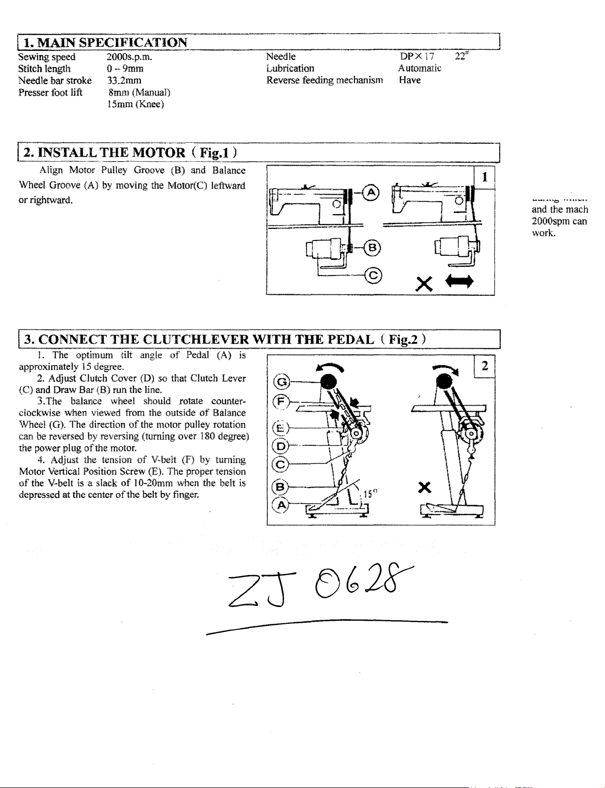
and the mach
2000spm can
work.
3. CONNECT THE CLUTCHLEVER WITH THE PEDAL ( Fig.2 )
L The optimum tilt ang!e
15
approximately
2. Adjust
{C)
and
Draw
3.The
clockwise
'Wheel (G).
be reversed
can
the
power
plug
4. Adjust the tension
Motor Vertical
of
the V-belt is a slack
depressed
at
degree.
Clutch
Bar (B)
balance wheel should rotate counter-
when
The
the
Cover
run
viewed from the outside
direction
by
reversing (turning over 180 degree)
of
the motor.
Position Screw (E).
center
of
the
of
of
of
1 0-20mm when the belt is
the
of
Pedal
(A)
is
(D)
so
that Clutch Lever
line.
of
Baiance
the motor pulley rotation
V-belt (F)
The
belt
by
by
proper tension
finger.
turning
Page 2
REPARATION
l)
Cleaning the machine
Before leaving
coated with
hardened and contaminated by dust during storage and
shipment.
test
be
This
2}
Examination
Although each machine is confirmed strictly and
before leaving the factory, the machine parts may
loose
or
deformed after long distance transportation
the factory, the machine parts are
rust~preventive
grease must be removed with gasoline.
AND
LUBRICATION ( Fig.3 )
grease, which may
be
with jolt. A thorough examination must be performed
after cleaning
see
if
uneven resistance or abnormal noise.
adjustment must
operation.
3)0iling
( l) Required amount
Line (A)
Line
the machine. Tum the balance wheel to
there is running obstruction, parts collision,
If
these exist,
be
made
accordingly before run in
of
oil
on
the oil reservoir: Max. oil level
(B)
on the oil reservoir:
Min.
oil level
If oil level goes down under Line (B), oil cannot
be distributed
causing
the parts a seizure.
to
each
part
of
the machine, thus
C:!>
Replenishing
Always
high
speed sewing.
use
only
Be
No.l8
special machine
sure
to replenish oil
before starting operation. ·
(3) Replacing oil
To
replace oil, remove Screw
After completely draining off
reservoir
reservoir with fresh oil
and
securely tighten Screw (C), then
oiL,
to
(C)
to drain oil.
clean
oil
Line
the
fill
for
(A)
oil
the
js.
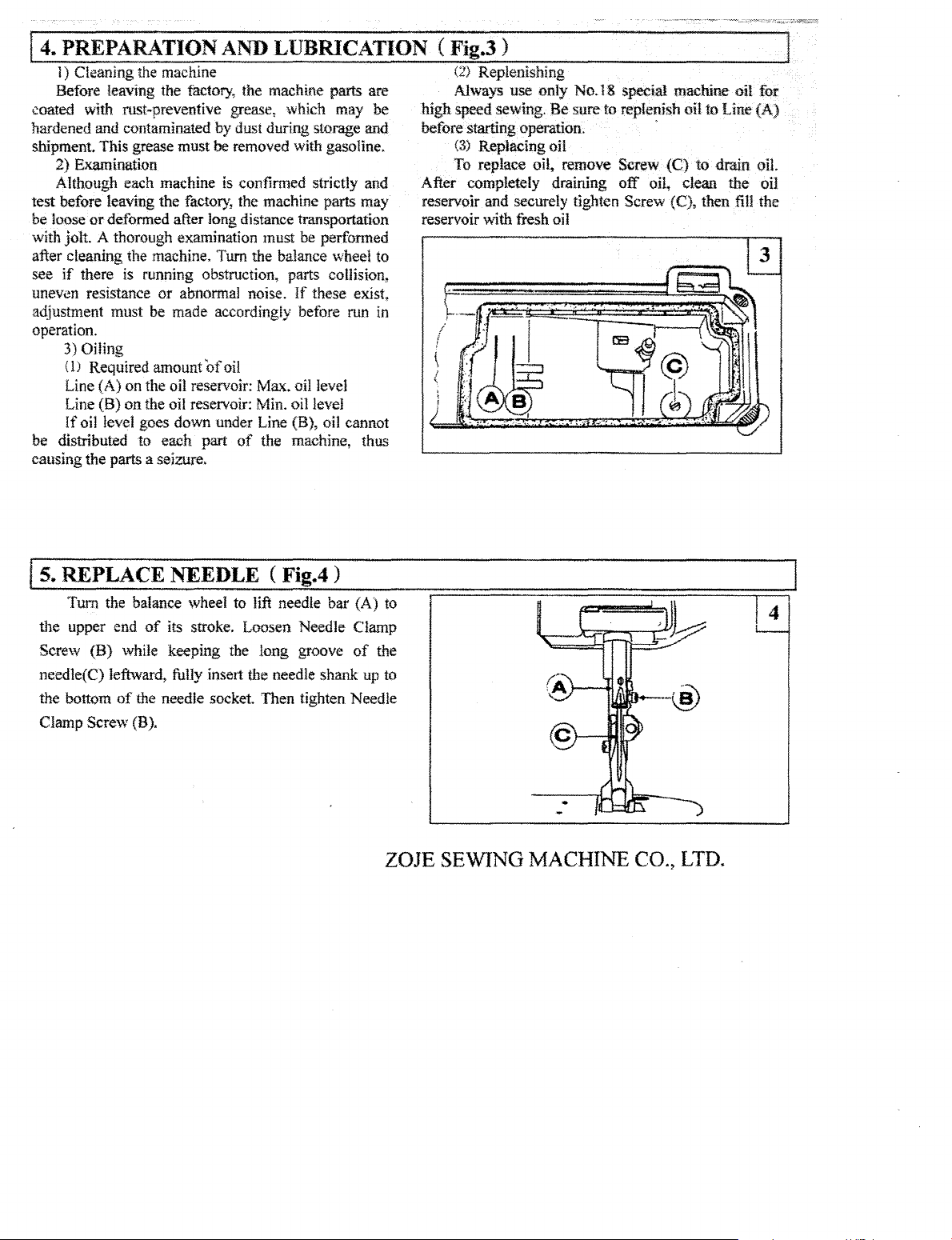
REPLACE NEEDLE ( Fig.4 )
Turn the balance wheel to lift needle
the
upper end
Screw (B) while keeping the
needle(C) leftward,
the bottom
Clamp Screw (B).
of
its stroke. Loosen Needle Clamp
long
fully insert the needle shank up to
of
the needle socket. Then tighten Needle
bar
groove
(A) to
of
the
ZOJE
SEWING
MACHINE
CO.,
LTD.
Page 3
6.RUN IN OPERATION (Fi .5)
Run-in operation is required for a new sewing
machine.
a considerable length
arm
the red oil hole (D).
( l 000-1500spm)
through Oil Check Window (C).
30 minutes. After a lapse
during which the working speed is increased
and the machine runs sufficiently well, the high speed
2000spm
work.
or
a sewing machine !eft out
of
time.
1) Remove Rubber Plugs (A) on the
and replenish sufficient amount
2) Lift Presser Foot (B).
3)
Run the machine at a low speed
to
check oil distributing condition
4)
Perform run-in operation at 1000-i500spm for
of
can
be adopted according to the nature
of
operation for
of
oil, and also to
one month
top
of
gradually
of
the
service
of
the
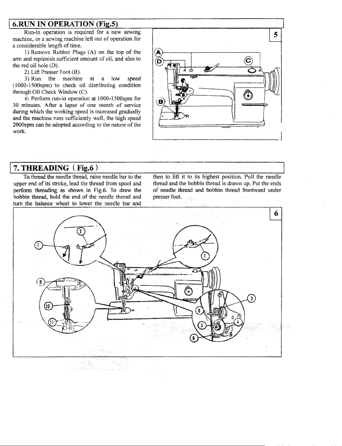
7. THREADING ( Fig.6 )
To.
thread the needle thread, raise needle
of
its
upper end
perform threading
bobbin thread, hold the
tum
the balance wheel to lower the needle
stroke, lead the thread from spool and
as
shown in Fig.6. To draw the
end
of
the needle thread and
bar
bar
to the
and
~-®----
~-~----·
then to lift
thread and the bobbin thread is drawn up.
of
needle thread and bobbin thread frontward
presser foot.
it
to
its
highest position. Pull the needle
~
--==~,
-~
?
Put
the ends
under
Page 4
Js.
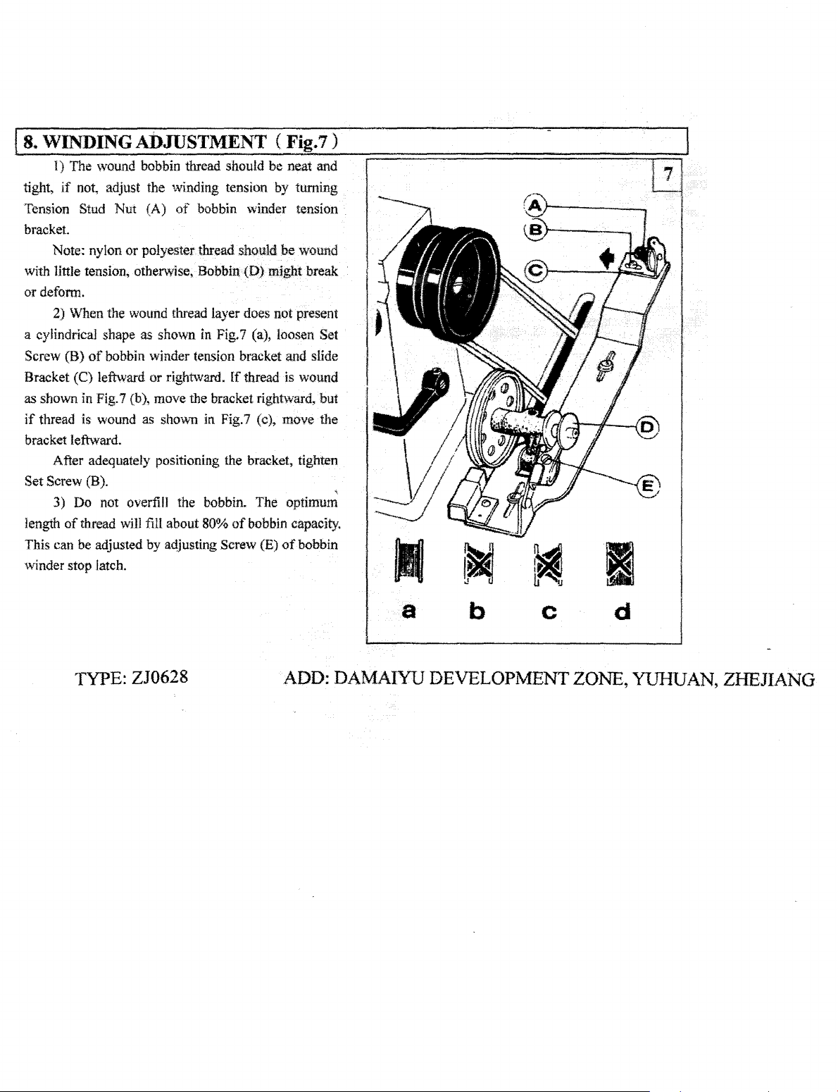
WINDING ADJUSTMENT (
l)
The wound bobbin thread should
tight, if not, adjust the winding tension by turning
Tension
bracket.
with little tension, otherwise, Bobbin
or deform.
a cylindrical shape as shown in Fig.7 (a), loosen Set
Screw (B)
Bracket (C) leftward
as
if
bracket leftward.
Set
length
This can be adjusted by adjusting Screw (E)
winder stop latch.
Stud Nut (A)
Note: nylon
2) When the wound thread layer does not present
shown in Fig.7 (b), move the bracket rightward, but
thread is wound as shmvn in Fig.7 (c), move the
After adequately positioning the bracket, tighten
Screw (B).
3) Do not overfill the bobbin. The optimum
of
thread
or
of
bobbin winder tension bracket and slide
will
of
bobbin winder tension
polyester thread should
(D)
or
rightward.
fill about
ff
thread is wound
SO%
of
Fig.7)
be
neat and
be
wound
might break
bobbin capacity.
of
bobbin
'
~
TYPE:
ZJ0628
ADD:
a
DAMAIYU
b
c
DEVELOPMENT
d
ZONE,
YUHUAN,
ZHEJIANG
Page 5
..:..9.:...:S::.:.E:.:T:......:S:.:T:.;.:IT.::..C.::.H=·
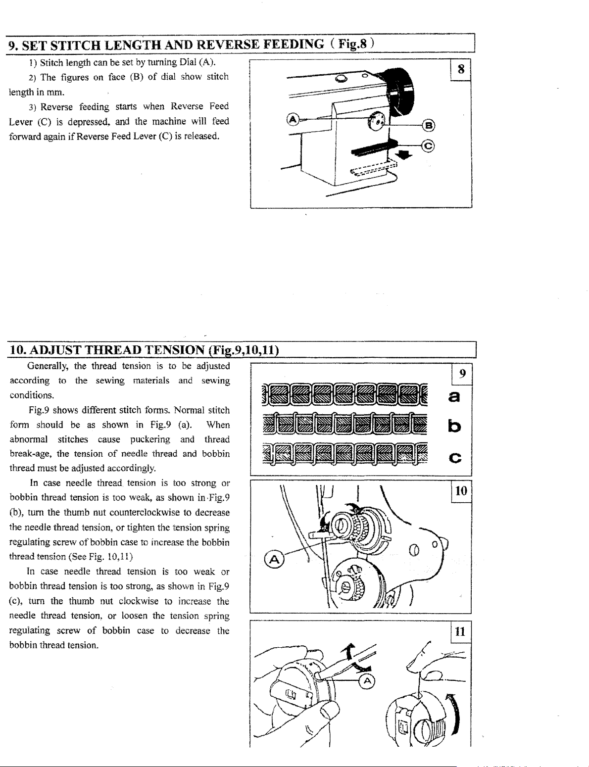
i)
Stitch length can
2}
The figures on face (B)
length in mm.
3)
Reverse feeding starts when Reverse Feed
Lever (C) is depressed,
forward again
if
-=L=E:.::...N:....:G:....:T...:::.H:.:..::A...:::.N_;_D~R-=EV_ERS
be
set by turning Dial (A).
of
dial show stitch
and
the machine
Reverse Feed Lever (C) is released.
will
teed
_____
"E_FE_E_D_I_N_G_(
F_i~g._8_)
-----·~
10. ADJUST THREAD TENSION
Generally, the thread tension is to be adjusted
according
conditions.
form
abnormal stitches cause puckering and thread
break-age, the tension
thread must
bobbin thread tension is
(b), turn the thumb nut counterclockwise
the needle thread tension,
regulating screw
thread tension (See Fig. 10,11)
In
bobbin thread tension is too strong, as shown in Fig. 9
turn the thumb nut clockwise
(c),
needle thread tension,
regulating screw
bobbin thread tension.
to the sewing materials and sewing
Fig.9 shows different stitch
should be as shown
of
be
adjusted accordingly.
In case needle thread tension is too strong
too
of
bobbin
case needle thread tension
or
of
bobbin case to decrease the
forms.
Normal stitch
in
Fig.9 (a). When
needle thread and bobbin
weak, as shown in·Fig.9
or
tighten the tension spring
ca..<;e
to
increa<se
is
too weak
to
increase the
loosen the tension spring
(J3'i
to
decrease
the bobbin
or
or
Page 6

.Adjustment
Loosen the stopper screw (B) and
egulating ring
he
thread take-up spring, or move the regulating ring
C) rightwards to increase the
djustment, tighten the screw
. Adjustment
Loosen the nut
egulating screw (F) clockwise to decrease the tension
f the thread take-up spring,
crew
'hen tighten the nut (D)
of
the thread take-up spring stroke
move the
(C)
leftwards to decrease the stroke
stroke. After the
(B)
.
of
the thread take-up spring tension
(D) and screw (E) and turn the
or
tum
the regulating
(F) counterclockwise to increase the tension.
and the screw (E).
of
~HEJIANG
PROVINCE,
CHINA
TEL: 800857-6715
FPLX:
0576-7332702
Page 7
!t2.TIME
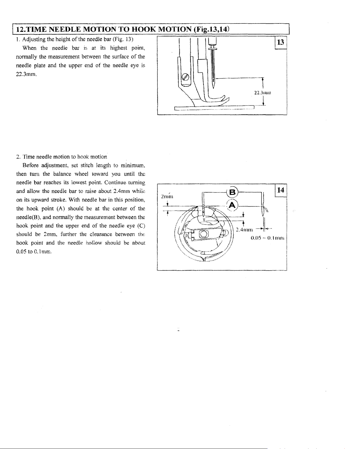
L Adjusting the height
When the needle bar
nonnally the measurement between the surface
needle plate and the upper end
22.3mm.
2. Time needle motion to hook motion
Before adjustment,
then turn the
needle bar reaches its lowest point. Continue turning
and allow the
on its upward stroke. With needle bar in this position.
the hook point (A) should be at the center
needle{B),
hook point and the upper
should be 2mm. further the clearance berween
book point and the needle hollow shouid be about
0.05
to
NEEDLE MOTION TO HOOK MOTION
of
the needle bar (Fig. 13)
i~,
at its highest point,
of
of
the needle eye ls
set stitch length to minimum,
balance wheel toward you until the
needle bar to raise about 2.4mm whik;
of
and nonnaily the measurement between the
end
of
the needle eye (C)
0,
l mm.
(Fig.l3,l4)
I I
the
------------------------------
the
the
Page 8
3. REPLACE ROTATING
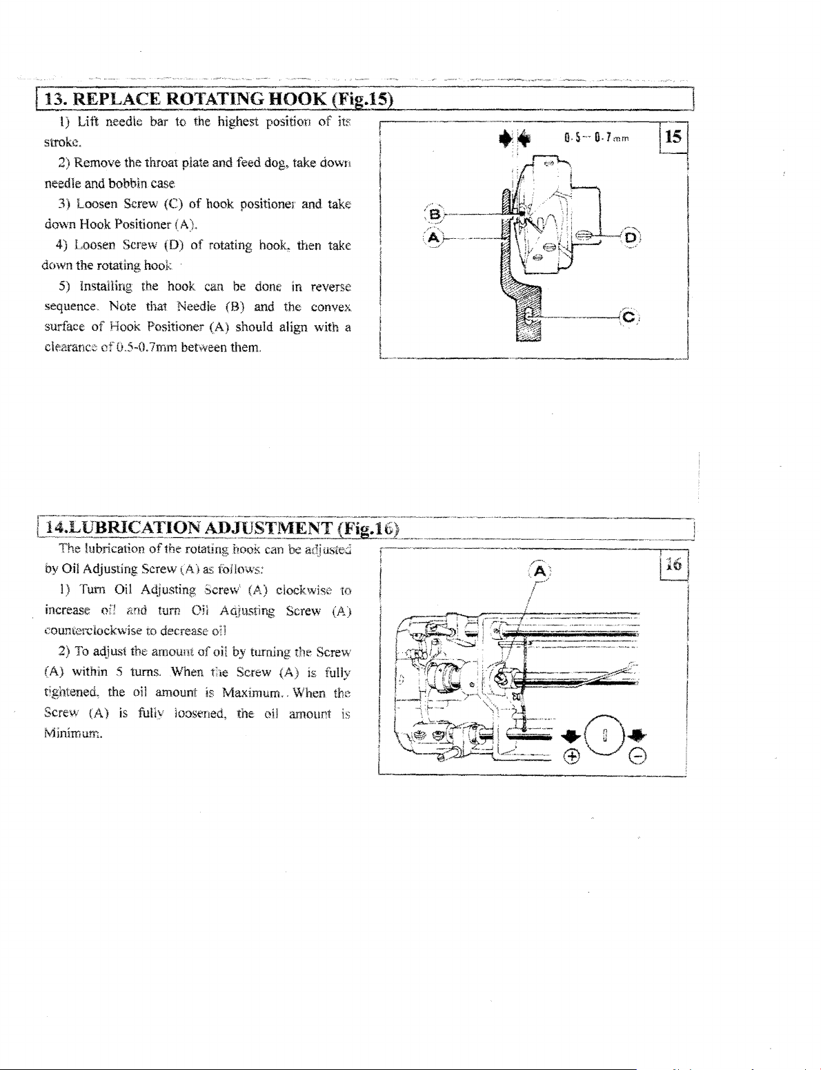
l)
Lift
needle bar to the highest position
strok.::.
2)
Remove
needle and bobbin case
3)
Loosen Screw
down Hook Positioner
4) Loosen Screw (D)
down the rotating hook
5) lnstaiiing the hook can be done in reverse
sequence. Note that Needle
surface
clenrance of0.5-D.7mm
the throat plate and feed dog, take down
(C)
of
hook positionel and take
{A).
of
rotating
(B)
of
Hook Positioner (A) should align
between them.
HOOK
hooL
then take
and the convex
(Fig.15)
of
its
\Vith
a
I
I
L
++
:)~}····--
(~}-
__
..
___
..
·-
..
_
_________
J
The
lubrication
by
Oil Adjusting Screw (A) as
J) Tum Oil Aqjusting .:,crew' (A) clockwise
increase oil
coumcrciockwise
2) To adjust the amount
(A)
within 5 turns. When t;ie Screw (A) is fully
tightened,
Screw
Minimurn.
the
(A)
of
the rotating hook can be adj ustei
f(>Jlows:
<1nd
turn Oil A4jtLsting Screw (A)
to decrease
oil
amount
is
fullv loosened, the oil amount is
o;1
of
oil
is
Maximum<,
by
turning the Screw
When the
to
Page 9
[t5.ADJUST
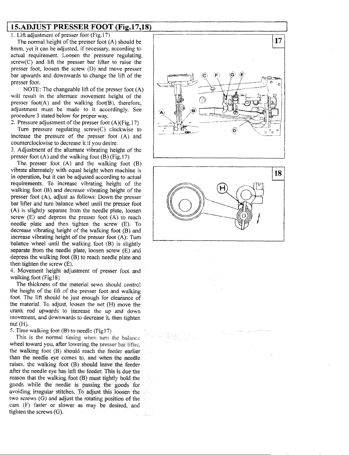
1.
Lift adjustment
The
normal height
8mm, yet
actual requirement. Loosen the pressure regulating
screw(C) and
presser foot, loosen the screw
bar upwards and downwards
presser
will
presser foot(A)
adjustment must be made
procedure 3 stated below for proper way.
Pressure adjustment
2.
Tum
increase the pressure
counterclockwise
3.
Adjustment
presser foot
The. presser foot {A)
vibrate altemateiy with equal height when machine is
in operation. but it can
requirements.
walking foot (B) and decrease vibrating height
presser foot (A), adjust
it
foot.
NOTE:
result
pressure regulating screw(C) clockwise to
PRESSER FOOT (Fig.17 ,18)
of
presser foot (Fig.17)
of
the presser foot (A) should be
can be adjusted.
lift the presser bar lifter
The changeable lift
in
the alternate movement height
and
to
decrease it
of
the aliemate vibrating height
(A)
and the walking foot
To
increase vibrating height
if
necessary. according to
to
(D)
and move presser
to change the lift
of
the presser foot (A)
the
walking foot(B), therefore,
to
it accordingly. See
of
the presser foot (A)(Fig.17)
of
the presser foot
lfyou
desire.
(B)
(Fig.17)
and
the
walking foot
be
adjusted according
as follows:
Down
the presser
raise the
{A)
to
of
of
of
actual
of
of
bar lifter and turn balance wheel until the presser foot
(A)
is
slightly separate from the needle plate, loosen
screw (E) and depress the presser foot (A)
needle plate and then tighten the screw (E). To
decrease vibrating height
increase vibrating
balance wheel until the walking foot (B) is slightly
separate
depress the walking foot (B)
then tighten the screw (E).
4. Movement height
walking foot (Fig
the
toot
the materiaL To adjust, loosen the net (H) move
from the needle plate, loosen screw (E)
The
thickness
height
of
The
lift should be
height
18)
of
the lift
of
the walking foot (B) and
of
the presser foot (A):
to
reach needle plate
adjusm1ent
the materia! sewn should control
of
the presser toot and walking
just
of
presser foot and
enough for clearance
to
reach
Tum
crank rod upwards to increase the up and down
movement, and downwards to decrease it, then tighten
nut (H).
5. Time walking foot
This is the normal timing when turn the balance
wheel toward you, after lowering the presser bar
the walking
than the needle eye comes to,
raises, the walking toot
toot
after the needle eye has left the feeder. This is
reason that the walking foot
goods while the needle
(B}toneedle
{Fig17)
(B) should reach the earlier
and
when me needle
(B)
should
(B)
must tightly hold
is
passing the·. goods for
me
due
feeder
avoiding irregular stitches. To adjust this loosen the
two screws
cam (F) faster
tighten the screws (G).
(G)
and adjust
or
slower
the
rotating position
as
may
be
desired,
of
and
the
the
and
the
(B)
the
the
and
and
of
the
the
the
the
Page 10
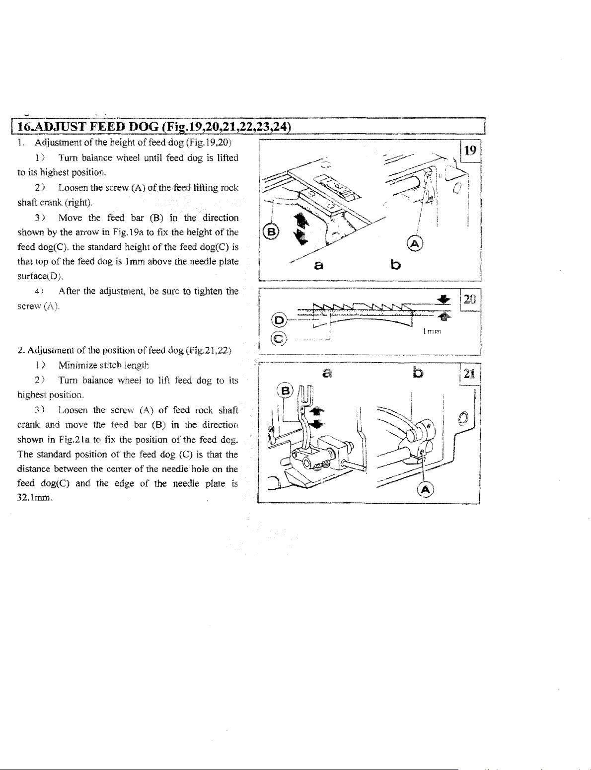
16.ADIDST FEED DOG Fi .19,20,21,22,23,24
1.
Ac\justment of the height
l )
Tum
balance wheel until feed dog is lifted
to
its highest position"
2)
Loosen the screw (A)
shaft crank (right).
3)
Move the feed
shown by the arrow in Fig. 19a to fix the height
feed dog(C). the standard height
that top
surtace(D).
screw
of
the reed dog is 1 mm above the needle plate
4;
After the adjustment, be sure to tighten the
of
feed dog (Fig.19,20)
of
the
feed lifting rock
bar
(B) in the direction
of
the feed dog(C) is
ofthe
a b
2. Adjustment
1 ) Minimize stitch lengit
2 )
highest position.
3)
crank and move the
shown
The standard position
distance between the center
feed dog{C) and the edge
32.lmm.
of
the position
Tum
balance wheei to iift feed dog to its
Loosen the screw (A)
feed
in
Fig.21 a to fix the position
of
the feed
of
feed
dog
(Fig.21 ,22)
of
feed rock shaft
bar (B) in the direction
of
the feed dog.
dog
(C) is that the
of
the needie hole on the
of
the needle plate
is
Page 11

4 ) After the adjustment, be sure to tighten the
screw (A).
1
3. Relative
the
needle hole in the feed dog.(Fig.23)
Make sure that
center
1 ) Remove the arm side cover
screw(A).
2)
center
screw(
4. Time feed motion to needle motion (Fig.24)
The standard timing
motion is that the teed dog starts moving forward
when
If
feed motion
as follows:
I)
Remove the
(A), (D)
2) Holding feed and feed lifting eccentric {B) and
turn balance
on the feed and feed lifting eccentric aligns with mark
(F).
When
feed
should be 0.3*0.5mm.
After the adjustment, be sure to tighten the screw
(A),
(0).
position adjustment between needle and
needle can be descended to the
of
the
needle hole,
Holding the needle bar and move it to the
of
the needle hole
A)
and replace the
the needlepoint reaches the needle plate surface.
is
arm
of
the feed and teed lifting eccentric.
wheel slowly until the reference hole(C)
adjusting, the clearance between
lifting eccemric (B) and eccentric sleeve{E)
if
not, adjust
in
the feed dog.
arm
side cover
of
feed motion to needle
not timed
side cover and loosen the screw
to
it
as follows:
and
loosen the
the
tighten
needle motion, adjust
feed
and
I
32.lmm
Page 12

.
[j
7.
REGULAR-~~E~~G~-(Fig.25,2·6~27}
1
.C
eant·ng.
l
Rem~ve
lint between the
2.Cleaning rotating hook
Swing
out
Wipe
the bobbin case with soft cloth
3.Cleaning oil
Swing
out
ihe oil pump screen.
~'eed
do::r
the
~hroat
;;ate
and
dear
off
the dust and / l
feed
and teeth slots. t
the machine head and clean the hook.
pump screen
the machine head and clean the dirt on
-----------·-·······
========;::,
=·=··-.::
25
l
i
Page 13

----------------------------!!1
'
-
I
•
!
l
1
I
.
I
'
i
I
~
~
i
~
i
,,
1
'
j
I ,
' I
; i
i i
' I
t '
I I
~
!
! I
I I
: I
ll
i
!
l
I
I
I
I
I
'
I
I
I
I
I
i
I
I
I
I
I
I
Page 14

1.
AR:"l
BED
AND
No.
1
2
·'
4
5
6
1
8
9
10
l1
12
13
14
15
!6
17
18
!9
20
2~
I
22
:3
I
24
I
25
26
27
2R
19
30
J!
I
·~
·'·
33
3.:1.
35
36
37
38
39
4()
4l 7J05-0J..()l0
42
43
44
45
46
47
48
49
50
51
52
53
54
55
58
59 22T!-003C6
60
61
62
Ref.
-01
-001
l-004
\-{)()6
No
B2
7J05..()!-00!A:!
l.J07
I 7_!07-0!-002
!
GB827-&6
j
ZJOS-01·003
ZJOS-0
ZJ05-0 l-005
7..!05-0
I 22TI-003C6
! 22Tl-t)()3C5
\ 22Tl-003C6
ZJ05-0l-()l-l
.
ZJOS-01..\.l!
'
1 72Tl-Ol7
ll2Hl-007CI
ll2Hl-007C2
l22Tl-009E l
22Tl-009E2
122Tl-t'!()9EJ
i22TI-OG9E4
I GB896
!
22THXl9E5
I22TI-010
I22Tl-Oll
17.J05-0!-007Cl
I ZJ05-0HJ07C2
!
ZJ05-G!-OOIC3
73TI-002C!
ZJ05-01.007C4
ZJOS-lH-007C5
ZJ05-0l-007C6
7.J05-0l-001C7
ZJ05.0 l-007('8-l
ZJ05-0 l-007C8-2
7J05-0 J
ZJ05-ll l-007CHl
7.J05-0l-007C I l
ZJ05-0l-007CI2
72Tl-Ol3
ZJ05-0J-OO&
ZJ05-0
7J05-0l-01!
ZJOS-0
22Tl-011
72Tl-Ol4
72T1-0l3
22Tl-022
72Tl-O!O
GB93
ZJ07-0l-003
72Tl-019
22TI-021Gl
22Tl-02JG2 Slide
22TI-02JG3
ZJOS-Ol-013
ZJ03-02-00 l
72T!
72Tl-Oil
72Tl-009
.•
(}07C9
!-OtW
l -0! 6
-00-1C4
5
A3
ITS
ACCESSORIES
Descnp1ion
Arm
Ann
bed
Trade mark
Trade mark
Face
Set
Knock
Thread
Set
Thread
Set
Arm
Gasket
Set
Oil
0-ring
l
Screw
Spring
Disc
Space
Stop
Pretension thread guide
Three-hole
Set
Thread tension bracket
Thread tension
Tension
Thread
Thread
Thread tension disc
Stop
Pin
Thread'comroHer
Thread
Screw
Thread tension release plate
Screw
Thread
Screw
Thread
Thread take-up spring 1
Tension thumb
Thread
Screw
screw
Cloth guide plate l
Screw
Bed
Rubber Plug
Retaining washer
Needle
Screw
Slide
Screw
Thread guide
Felt
Set
Rubber
Rubber
Rubber plug
plate
plate
plate
screw
pin
guide
(up)
screw
guidi!"Tiiliddk)
screw
;ide
cover
for
arm
screw
check
window
type
tension
for
pretension
for
pretension
for
pretension
ring
thread
sere"·
regulating nut
tension
tension
releasmg
disc
controller
tension
controller
take-up
supportor
plate
board
board
spring
(Joy,-er)
for
thread guide (lower)
Screw
plug
plug
rivet
side
guide
stud
spring
dtsc
disc
release
stud
nut
spring
cov.:r
stud
disc
pin
srop
l
l
I
9 2.5 X S
2
l
!
!
1
SM9/64"
l
l
!
, SM9/64
l
'
i
'
l
\
I
I
l
1
SMlli64''
8
1
1
l
1
2
I
Ring 3
l
I
I
l
SMll/64"
1
l
1
l
l
I
~
'
1
1
1
I
SM3!32" (2.38)X
1
1
2
l
SMll/64"
l
1
I
1
SM5Y64"
1
SMll/64"
1
2
3
J
Washer6
3
1
SMll
2
l
l
SM3/32" (2.38) X 56!2.2
2
l
l
SM9!64
1
,p
11.8
4
1
"'5.7
tl>
8.8
1
Remark
(3 .57) X 40/6
~
.
.,
(3
57}
X 40/6
(07)X
40/9
(4.37)X 40!5
56
(4
37)X
4015.5
(3.57)X 40!6
(4.37)X 40/5
/64" ( 4.37) X 40/8
'·'
(3.57)X 40/6
ZOJE
SEWING
MACHINE
CO.,
L
Page 15

j2l
! I
l
·~--··-
I
I
I
j
l
Page 16

•
2.
NEEDLE
No.
1
ZJOS-02-{)0l
~
~
7J05.02.{)02
3
22T2-tl02
4
I ZJ05.02-l103
5
l ZJ05.02-004
6
2ZT8.0!iC4
.
7
ZJOS.02..005AI
s
22'1'2..(){16
9
22T2.007
10
l.JOS-4)2-006
'
ll
72T2-004B2
l2
ZJ05-02-007
.·
13
l..l05-02-(l08
14
22T7-0l5
!5 7JOS-02-oo9Bl
16
ZJ05.02-0G9B2
17
GBII7
.
l&
l.J05-02-009B3
19
ZJ05.02.009B4
72'1'2-003
20
ZJOS-02-010
21
lJ05-02-01l
22
22T2-002
23
·-·
ZJ05-02-0l2
24
..
ZJ05-02-n
25
27
2212-i)JI
28
ZJ07-02-iXl1Cl
29
7.J02-08..007
30
lJ07
3!
12T3-005Dl
32
ZJ05.{15-003
:>3
7.J05-03·0l5
34
ZJ05-02-0 16
35
22'1'2-002
36
BAR
Ref
No
-02..00 I
AND
TAKE-UP MECHANISM
! - Description
,
Thread take-up lever
I
Hinge
pin
I Set screw
I
Thread
take-up
Oil-guard
Set
screw
I Needle
bar
crank
Set screw
Set
screw
hinge pin 1
Setscrew
Needle bar
Needle bar adaptor
Set screw
·
Needle
Crank (left)
Pin
Slideblockforneedlelr..rrockfrn.me
Position bracket
Screw
Needle
Hinge pin l
Screw
Needle
Thread guide for
l?
Needle
Needie clamp screw
Crank
Screw
C2
Crank
a3
Screw
Hinge
Bushing
Bushing for rock shaft (right)
Screw
link
bar
rock
for
crank
bar
rock
bar
(right)
lever
(right)
pin
(upper)
for rock shaft {left)
lever
frame
link
driving
frame
needle
(3.57)X
..
(7.14)X
(7.14)X
(6.3S)X
.,
(3.57)X
A3 X 16
(4.37)X
(5.95}X 28J!O
17 12 #
(3.l8)X
''
{6.15)X
(5.9S)X 28!6
(5.95)X
Remark
IPi~cci
1 I
1
I SM15!64" {5.95)X
~
I
l
stud
!
'
l
I
1
SM9/64"
l
SM9/32"
l
SM9/32"
l
2
SMl/4"
l
1
I
I
SM9i64
I
I
rock
shaft
!
1
1
Taper pin
1
l
SMJ1!64"
1
l
1
SM15/64"
l
1
bar
1
DPX
SM!i8"
l
1
SMli4
l
1
1
SMl5!64"
1
1
l
SMl5164"
2
ECJ
2
28il0
2
4014.5
28/13
28114
40/6
40/J 1
40!8
44/4,5
24/16
23/JO
TYPE:
ZJ0628
Dl
Page 17

l
f F 1
'f
13\
I I !
~~
I l
I
I
l
'
I
a
@
@@
IC!?I
t J t /
, , 1
~
A
I
I
Page 18

3.
ARM
SHAl'T
No.
ZJ05..03..001A!
l
2
22TI..OO!A2
3 22T6-005Bl
4
2213-00282
5
21T3·003
6
ZJ05..03..007
'"
7
:2:?:T2""'J02
8
ZJOS-03·006
9
22T3·006F
~22T3-006F2
-~
ZJ02..03..00l
10
11
122T3-007C2
12
2213-008
72T3..005Dla3
1.3
!4 l 1H3-002Blal Feed lifting eccentric 1
·:;
15
72T3-005Dla1 Eccentric
:
22T3-009Dl b
16
17
ZJ04-03..002A2
JS
ZJQ7.Q3-00!B2
;
19 ZJ05-03-003
22T3-0JOE2al-2
20
22T3-0lOE2a2-2
21
~0
~~
I 22T2-005B3
j
23
122T3-010E2bl-Z
24
22T3-0 l
·'
\:
25
ZJ05-03-\l04
-~
26 ZJ05-03-005
27
22T2-002
1
Ref
AND
No
OE2b2-
VERTICAL
Ann shaft
Rubber
ol!ar
C
Set
screw
Ann shaft
Arm shaft bushing (middle)
s;;rscrew··
Arm
Oil
seal
Spring for
Balance
Set
screw
Set
screw
Ser
screw
Retaining
Crank
Feed
Venical
Bevel
Bevel
Set
screw
Bevel gear
Bevel
2
Vertical
Vertical
I
Set
screw
SHAFT
Description
plug
tor
arm
shaft 1
hushing
'
~haft
bu5hing
oil
seal
whc~l
sleeve
ring
rod
fur
feed
forked
connection
shaft l
gear
for
arm
gear
for
vertical
for
hook
gearforverw;al
shaft
bushing
shall
hushing
(left) !
(right)
lifting
shaft l
shaft
shaft
shaft
(upper)
(]ower)
M:ECH..<\NISM
:1
2
SM!/4 ''
I
1
1
1
i
l SM15/64'' (5.95)X 28/10
'
·I
1
J
1
2
SMJ5!64" (5.95)X 2Sil.2
l SMJ !!32" (8.73)X 28/iO
2
SMl5!64"
l
1
rock
1
I
(upper)
J
g
SM1!4 '' (6.35)X 40i7
l
(lower)
1
l
J
SMl5!64
2
Remark
(6.35)X 40/4
(5.95)X 2S/7
.,
(5.95)X
28ti0
;
i
••
,.
ZJ0628
I
f
I
i
AI)D:
·.·
;·:
DAMAli!J.J:)EVELOPMENT ZONE, YUHUAN, ZHETIANG PR(
Page 19

I
I
14l
l · I
\ !
l j
f
t
I
I
I
I
r-_
.. _ ... _ ..
......
........
..........
"'.
"",.,.-,..,.,.
l
'
l
'
-
~---
~--.-
-·---
...J
... -...
--
....
...
--
...
,...,..
,..
...
-
..
-·
...
...
--
!
I
I
I
Page 20

4.
HOOK
SHAFT
Ref
No.j
i
1
2
3
4 22T4·001Alal
1
5
6
122T4-003G
]
! 22':'4AJU4
8 1
9
122T4-006
10
1
tl
12
l3
14
lllH4-001
15
16
l
l
No
lJ05...()4..1)()1
72T4·002B!
12T4-002B2
~2T4·00!Ala2
nT4-ow
7..107-04--l){)
zzn-oo2
HSM-A(5)
BC-STH
74<4-004
22T4·015 Set screw
MECHANISM
I
I Rotating hook shaft
' -
J
Description
Collar
for
hook
se1
screw
Filter screw
Filter
Oilseal
for
rotating
i
Honk
.>naft
bushing
oii adjtt>ting screw l
Spring
for
ml
adjuster
Hook
shaft bushing (right) l
Set screw
Rotating hook complete i
Bobbin case
Bobbin
Rotating hook positioner
shaft
hook
shaft
(left)
:;;; res
~
4
i
l
l
\
l
1
l
l
!
1
I
I
I SMl5164.,
I
SM3!l6'
t
I
SM!5!64"
SMll/64"
Remark
(5.95)X
(4
76)X
(5.95)X
(4.3/)X
28!4.5
32
28!10
40/lO
i
.,
1
:]'
!
n
l
i
'
I
I
!
i
I
!
!
I
I
Page 21

r
,
I I
I I
' }
:
5
I
l
I
l
I
!
Page 22

5.
FEED
LIFTING
No. i
2 72T6-00!A6
3
4 ZJ07-05-0C>l
6
;
lO
J
!l
j
i2
-,,--
14
15
-~
16
i p
19
1
c
2!
24
25
.;
··~
26
27
'·i
28
.c,
29
/
30 GBS94
t
31
']
32
34
35
36
3 7 22T6-00 l A6
38
39
40
41
Ref
, I
21T6-0tl!Ala
ZJll-0&-00JAi
5 22T6-00 l/14
llHt-004
f 22T2-019
S
llH6-007
72T6-00lA5
llH6·006
22T5-00iA4
l1H6-00!
llH6-00S
72T4-002B2
GBS94
22T15-005Bl
22T3-002B2
ZJ07-05-003 !8
22T6-00llllb
7.J07-05-002
31H4-0!4
72T6-002B! b
GB70
72T6-007D
72T6-002B4
72T6-002B2
llHMllO
54T6-002
22T6-0l2
22T2-002
22T6-il13
22T6-005Bl
:Z2T3-002B2
72T6-003C 1
22T6-007
22T6-00lA1h
72T4-002B:Z
ZJ02-08-012
ZJ02-08-048
72T6-007Dlh
MECHANISM
No
j
!
! Screw
·Feed
ia
feed bar
Screw
Feed
bar
hed
dog
Shall
thr
Screw
Bushing
Oil braid
Bushing
Scr~w
Fe~d
rock
Bushing
Screw
C-typc stop
Collar
rock
Screw
Feed
liflingrock
Hmge
Screw
Feed
lifting
Oii
bratd
FeNi
lil1ing
Bushing
Screw
C -eype stop ring
Washer
Collar
Screw
Feed
lifting
Hinge pin 1
Screw
Washer
Screw
Washer
Screw
Washer
Description
~rank
f~ect
for
feed
for
f~d
shaft
fer
feed
ling
for
feed
shaft crank
pin
connecti;m
rock
fer
feed
forfeeJ
rock
nut
bar
rock
shaft(let1)
rock
shafl(nght)
ro<:k
rock
shafm;;nk
shaft
lifiing
lifting
shaft
crank
shaft
shaft
sleeve
rock
rock
SM3!16
I HG128-C
1
2
SMiiS
1
1
SMlli64"
1
2 5 X
SMl5i64'
SMJ5t64'"
I :
ring
SMlf4"
SM3!l6"
(left)
i i
M5 X 12
shaft
1
SM!5164" (5.95\X 28!10
'
ring
sllaft
SMl/4"
2
(right)
l
2 SMJ!l6" (4.76)X
!
l SMl5!64
l
1
SMJ5i64"
l
¢2.5
.,
(4.76)X
'·
(3 IS) X
(4.37}X
315
(5.95)X
f5.95)X
l5
(6.35)X
(4.76)X
X 265
15
1,6.35)X 40/4
,,
(5,95)X
(5.95)X
Remark
44,15
4014
28!1
4018
23/10
18!4.5
2&!11
28!12
28!43
2.8
5
Page 23

&I
I
'
J
:®
;
Page 24

6.
STITCH LENGTH REGVLATING MECHANISM
I!'<\,
!
.!.
l.j
ji'
: S
IS
Ref
1
lzJOl-Ot>-00lAl
ZJfll·Ot>-OU\t\2
DOl
·t'6·0U)
I
'
i
22'f5~00lA4
( 73T5-(hJ2B!
I
LH!5~06-tl07
I
'2T~·OU
71T5-006C
Li07-Ut\-OfJ:ZDI
N"
I
!
j
\
flin;t
!-~~d
Fted
Hwge
Rubber
Spnng
Dt~.:ripnvn
pn
regulator
!cgu!ator
hushing
pm
f0r
teed
regulator
piug
!Or
stopper
pm
; X l Y
\Vas
he•
Page 25

-
r I
I I
' I . l .
-----~!
~I
~
I
I ! I
l
l
I
~)
I
I
I
I
!
!
I
®
I
I
J
!
i
i
f
!
l
'
~
'L_
____________
""'\
\
\
'
\
__
~
j
!
(
\
'
I
j
l
i
l
Page 26

:.
PRESSER
7)05-07
..
i
iJ05-DU02
- i
ZJ05-07 -009 A i
7J05-D7-009A2
ZJ05-07..(JIO
ZJ05-D7
ZJ05-D7-UB
J.J05-07-Dl4
l~f05-07-01~
2.!1,5-D?-0!6
22T7-005.(l0! i
ZJ05.07-(ll
Z:ZT9-l.lOiNf
ZJ05..()7..(Jl9
25
FOOT
MECHANISM
..()01
..(J2l i Screv
Presser
Presser bar bushing l upper;
Screw
?r~sser
:>cr~"
Kne·:
~;;~w
ii
:'\e:rac:ing s;mng
s,·'""
! Nut
Des(.;nptiQn
kH)t
hftt>r
t-ar
spnng {ilaL
!iller litlmg
lever
hracke'
IP•ecesi
1
I
i
' ;
!
l I S,\i!
I
SMl5i64.
5}64
I
1:
I'
I
I
I
,.
(i.
-?5)
;, 2Si28
(5
95lX
2~
I
?B
ZJ02-08-00 7
29 ZJ05-D7-023
3()
ZJ05..()7-0ll
3!
Page 27

I ,
. 'a!
.I~
l
8.
PRESSER
!
No.
l
! ZJ05-08-00 l A 1
2 I 22T3-002B2
3 I
ZJOS-08-00
4 I
ZJOS-0&-00
5
GB893
o i ZJ05-08-ti02Bl
I
ZJ05~08-002B2
I
8 \ ZJOS-08-003
9
2::J05-08-0Q.J.
i C
ZJ05-0S-00:5
i 1
ZJ05-08...oo6
1
:1
ZJ05-08-00I
1 -
D02-0!\-004
22Ti-O; 1
i5
ZJ05-08-008
lf
ZJ05-08-00':I
!7
ZJ05-08-0lC
13
ZJ05-0l!-01l
ZJ05-08-0 l
ZJ05-DS-0!
22T2-00lA9
23
ZJ05-08-l'
ZJ05-08-0H'
2:'
ZJ05-(Ig.(J
26
ZJ05-0&..0
22T:;>OOiAS
2S
ZJ05-08-0F'
2¥
ZJDS-08-020
30
ZJOS-08-02;
~-. 12T24•~).: t ~crt-\'
32
G'f~-~·r! ~ \i{a~he~
,
<-::
ZJOS-08-022
t
···-··~-·--
Re~·
.......
~~-
LIFTING
No
1
A2
l A3
MECHANISM
[ Descriptio"
I
~irting
Screw
I
,
Lifting
i
Needle
I Retawing
!
Adjusting
I Set
scr"e\c
I
Screw
for!ifhmre;x'dlmco..xmecringroUar
i
Lifting
!
iVash<::
. I
N'J~
L1ftmg
Lifting
Sere;•·
Hmge
Hinge
Liftmg
lifting
o
...
~{'·:-c..":"'
~ • -·~·'""'~
:
't
.
.t
15
1T
ll',
....
V;orating
Vibrating
SCf¢\'\-
Vibrariug
Spring guide
'-.:;rev.
Shdebtickf()rqc;a;;::g
Scr"'"
i
·~·I>
seal
I
L\ftingrock:
---_1__-··-·----------'----'--
eccentric .
ecc:ennic
bearm£
ronnecnon ·
1 i
ring
crank
for
eccentric
oonnection
I
tece;,tnc
connectmg
rock
shaY
rock
shaft
bushing
pn:
pill
nut
l:Jeli
cranK
be!i
cran ;
;!p.-;'1"!:2"'
1;"'\C~
......
~~
......
t'!
...
pressi"r
presser
pres~<";·
ro.:l
pJ!\r.
s~aft
busmng
~llar
I !
! l
;nght'
ilni
~
$
ba-
foo:
~""
sp"ng
;;:~s;.;r'::;;
<)er(
!,Pi~ces:
.
Remark
1
~~~
2
1.
SM
L'4
'' ( 6.35) x 40/4
j
I'
:
i
i i
Ring 30
1
1
SM3.'!6'
!
l
~
"'
J
SJ\111/64
iSM
i
!
'
'
!
!
I
i SM 9!64
I
SM
SlVl
Wasi~c~
(4.76)X2~
;,
t-+.37)>:~
1!4.
(6.35)x
,.
13
~
9/64 ! 3
11
/o~
< 14.37)
5
57) X 40/6
57!>.:
I
4-0;~5.5~
4C
.
40'(-
~
..
~
40
:5_
')
Page 28

~
@--~
"-'
' .
---
!3
-~
--------
_
__.,
9.
LUBRICATING
No
Ref
7J03-09-00 i
7..107-09-002
12Tl-007
:-
'72T2-00~?
4
ZJ03-09-00:?
;
ZJ
03-09-D03
6
;
lHS-008Bl
k
i
H8-fJtf!
c
"2T2-00::'
9
'
lC
;
'
ZJ07-(19-003A
! '
22T8-010B'
i
~";,
ZJOS-09-00
!4
ZJ07-09-IJ04Bl
:22T8-013D::
ZJO
i
''
~
t.~
-0&-00-:;
7:271-Cr~.>
MECHAMSM
No
011
Oil
Wash~;
Sere\\
Oil
Oil
Oii
Gear
Oil
l
Oil
i
Cd
;
!
Pi:Je
i
Pipe
Description
;:n1mp
body
pump
body
pump shaf'
pump
body
pump
screen
(inner)
pipe
for
hook
J.npe
for
am1
pme
fOr
arm
connectton for
hotd
for
arm
plate
guide
piare
shaft
shaft (upper)
shaft
(!ower)
arm
s'::l;':.
shan
Remark
1
Sivfl
8
.,
(3.
18) X
3
3
4H
Page 29

. .
110
l f;.
OIL
r
I
:;-,;,;.,
!
l -
RESERVOIR
-~--·--·--,.......-
Ref
No
AND
OTHER
Oil reservoir
01l drain
ACCESSO~!£;~
Description
scr0w
. i
P1ecesj
I
:
i
Gaske~
l~'r
oil
reservoiq
22T9
..
;
l
f
~
! .
: 5 ; 22T9-003B6
lci
l 9 ,
:?C
~
, ;
.,~
i
::3
2L
l
25
.
!
26
f
?.
....
i
t.c~-.,.------·-·--..._
COiA5
; 22Ti!-003Bl
!
12l"9
..
Q03
B1.
! 221'9-00385
22T9-0NC
l
i 22TY-004C2
'
7~T
1
..
en
:
i 72T9-028 Screv·
l GN896 Stop
l
Z..J05~10-002
1.
GB84 Set screw !
, Chs;n I
GN1"'1
GoJketfo::\·11
Hmge
~t~acung
Kn'Z:~
Loc><
Knee
Knee
Set
screw
Bracket
Knee
Set
5c:rew
Pad
Beit
Belt
Screw
Knee
C'hain
______
rc~ervoir~smalr,
n·~
:';::
5-rxmg
liner
src:p
nu·
iifter Utin?
1ificr
ocU
for
knee lifter
lifter
plnc
for
knee
cover
bracke[
cover
plii·e
nng
lifter
rod
hool{
_._..,...
~':t'e
1·urknee
crac
cran:~
lifter
crank
...
__
b1g;
iifw·
ilr\t:;
~;,,.,
rod
plate.
plate
_...~,.,
...
_____
I
2
3
~
I
2
_.._........,
~
Page 30

{f.'J:
L
..
._:
,~-'"'
........-....
,., .
"~
.....
~.,
\
j
/j
··.~,·
i
!
t
'
i
t
i
!
I
Page 31

11.
ACCESSORIES
Ref
No
22T9-007F1
.,
72T9-004Ci
-
.;
7219-005 Rubber cushion (big)
7219-006 Rubber cushion (small)
5
2219-0! i
6
7 22T9-012
8
7219-007
9 7219-020
lC
7219-02:
No
Hmge
Rubber
Oiler
Magnet
Screw
Screw
Screw
of
driver
driver
driver
Description l Pieces
machine
socket
for
head
hinge
I
I
I
2
~~
..,
"
(long)
(medium)
(short)
11
''
!""'~
1~
,,:
~..:
72T9-022
2219-0
I-:-
2219-0i?
DP
X
17
21#
Double-end
Oil
container
Vinyl
cover
Needle
wrench
4
Page 32

~~
I
I
I
I
i
~
~
@;--..,_ _
_,
~
f
I
I
'
~
@)--~"'·--
:
12
. .BOBBIN WINDER MECHANISM
Ref
No
Z::T'J-00607
22T9-006D~
..
Bobbin
Sprinf
Screv.
fUvet
Sen.·\\
Bnhb1n
....
____
winder
winder stop
~·
DescripnoP
base
latch
P\eces!
J l
~
1
'
Bohbm
winder tension bracket
Tenswn stud bushing
22T9-006D2
22T9-006D22
i
Bobbin wmder tensmn spnng
Tension stud
Tension
bracke~
\!food
screw
Washer
nui
scrh~·
2
2
 Loading...