

zoeller M267, D267, N267, E267, WM267 User Manual
...
L2
Product information presented
60 HZ
here reflects conditions at time
of publication. Consult factory
regarding discrepancies or
inconsistencies.
MAIL TO: P.O. BOX 16347 • Louisville, KY 40256-0347
SHIP TO: 3649 Cane Run Road • Louisville, KY 40211-1961
TEL: (502) 778-2731 • 1 (800) 928-PUMP • FAX: (502) 774-3624
REPLACEMENT PARTS LIST
FOR MODELS:
FM0383
0117
Supersedes
0216
Visit our web site:
zoellerpumps.com
L1
WHITE
004620A
N267 NONAUTOMATIC 115V
E267 NONAUTOMATIC 230V
WM267 AUTOMATIC w/wired
BLACK
LS
S
GREEN
BLUE
BLUE
MOTOR
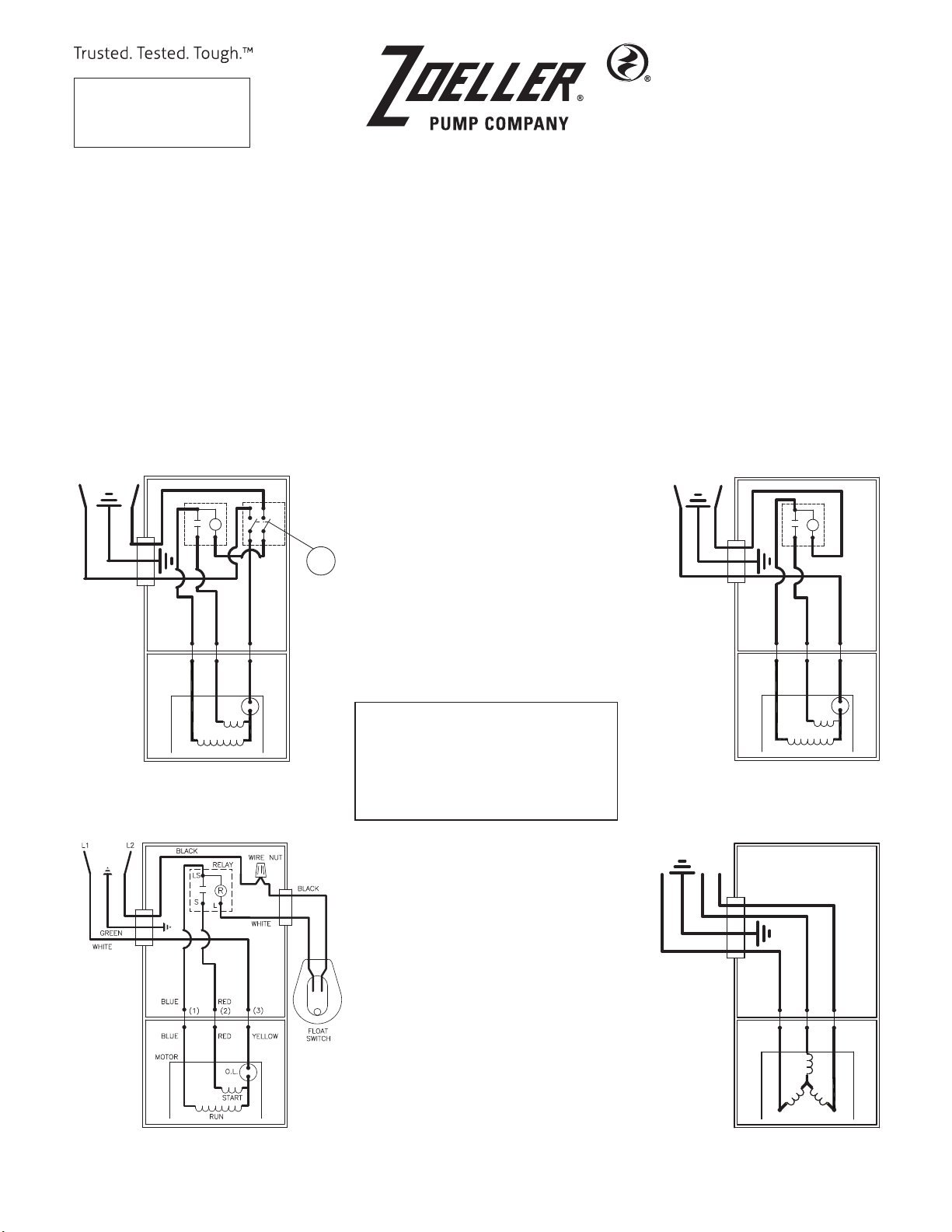
WIRING DIAGRAM FOR MODELS
“M267-F”, “D267-F”,
10/92 thru Current
M267 AUTOMATIC 115V
D267 AUTOMATIC 230V
oat switch 115V
RELAY
SWITCH
COM
3
1
R
L
RED
(1)
RED
RUN
and “H267-F”
(2)
O.L.
START
2
4
BLACK
WHITE
(3)
YELLOW
NC
FLOAT
TO ORDER REPLACEMENT PARTS
PLEASE FURNISH THE FOLLOWING INFORMATION:
• Model number
• Part number of pump
• Part number and description of part
H267 AUTOMATIC 200V/1PH
I267 NONAUTOMATIC 200V/1PH
J267 NONAUTOMATIC 200V/3PH
F267 NONAUTOMATIC 230V/3PH
G267 NONAUTOMATIC 460V/3PH
L2
L1
GREEN
WHITE
002395A
BLACK
RELAY
LS
R
S
L
BLUE
BLUE
MOTOR
WIRING DIAGRAM FOR MODELS
RED
(1)
(2)
RED
O.L.
START
RUN
“N267-F”, “E267-F”,
and “I267-F”
10/92 thru Current
(3)
YELLOW
004414
WIRING DIAGRAM FOR MODELS
“WM267-C”, “WM267-D”
10/92 thru Current
© Copyright 2017 Zoeller® Co. All rights reserved.
L1
BLACK
006848
L2
L3
RED
GREEN
BLUE
MOTOR
WIRING DIAGRAM FOR MODELS
“J267-F”, “F267-F” and “G267-F”
10/92 thru Current
WHITE
(1)
RED
(3)
(2)
YELLOW
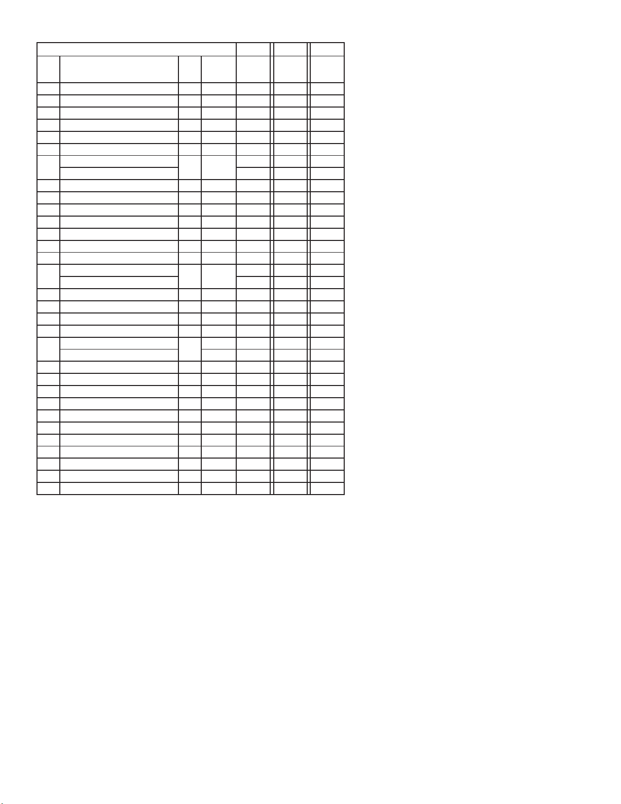
REPLACEMENT PARTS LIST FOR MODELS “M267”, "D267" & “H267”
MODELS: M267-F D267-F H267-F
REF.
NO.
1 Case & Switch Asm 1 3 004739 004739 004739
2 • Handle 1 267032 267032 267032
3 Case Mach. 1 3 004610 004610 004610
4 • Gasket,Case/Cover 1 267007 267007 267007
5 Relay Asm. 1 002474 147135 001536
6 • Wire Package (2 wires) 1 267014 267014 267014
7
8 Cord Terminal & Seal Asm. 1 4 094071 094072 006930
9 • Seal, Cord-Asm. & Strain Relief 1 4 094032 094032 011626
10 • Guard 1 267008 267008 267008
11 • Arm & Seal Asm. 1 3 004741 004741 004741
12 Switch Asm. 1 3 004740 004740 004740
13 Float 1 034019 034019 034019
14 Rod, Float 1 001526 001526 001526
15
16 • Seal, Motor Housing 1 267006 267006 267006
17 Washer, Thrust 1 002140 002140 002140
18 Housing,Pump-Mach. 1 003877 003877 003877
19 • Seal,Shaft-Asm. 1 267027 267027 267027
20
21 Base-Mach. 1 008646 008646 008646
22 Guide,Float Rod - Asm. 1 004676 004676 004676
23 • Oil,Dielectric 1 267056 267056 267056
24 • Seal,Thru Wall Terminal 3 003402 003402 003402
25 • Plug,Test-White 2 034090 034090 034090
26 • Screw 1/4-20 x 3/4 long - HH mach - SS 9 001916 001916 001916
27 • Screw #10-24 x 3/8 long - Round Head - SS 3 001883 001883 001883
28 • Screw #6-32 x 7/16 long 2 004644 004644 004644
29 • Screw #6-32 x 1/4 long 3 001877 001877 001877
30 • Screw 1/4-20 x 7/8 long - HH mach - SS 4 012491 012491 012491
¤ Rebuild Kit 1 004743 004743 004743
• Items included in Rebuild Kit. ¤Not shown in illustration.
DESCRIPTION
Housing, Motor & Stator (Regal-Beloit)
Housing, Motor & Stator (Emerson) 014797 008642 N/A
Rotor Asm. (Regal-Beloit)
Rotor Asm. (Emerson) 004021 004021 N/A
Impeller-Plastic
Impeller-Cast Iron 003884 003884 003884
QTY NOTES
1 1,2
1 2
1
10/92
thru
Current
002475 002476 003871
267005 267005 267005
150857 150857 150857
10/92
thru
Current
10/92
thru
Current
See page 3 for illustration.
NOTES:
1) Motor housing, bearing, stator & terminal are preassembled at the factory and must be replaced as a unit. Stator is permanently attached to the Motor Housing.
White test plug, seal and thru wall terminals are replaceable.
2) When ordering Motor Housing, Bearing, Stator and Terminal or Rotor specify either GE or Emerson motor. GE motor can be identied by (4) half oval slots spaced at 90°around
the outside diameter of the stator. Emerson motor can be identied by (2) half oval slots spaced at 180° around the outside diameter of the stator.
3) When ordering these parts, customer must identify if switch is a General Electric switch.
4) If an “X” follows Model No., or Date Mfg. on brass ID tag, consult factory for ordering any parts.
5) See FM0160 Parts Price Sheet for listing of parts prices.
6) “NA” indicates, not applicable.
7) Clamp, Strain Relief is not sold separetely, must order Seal, Cord Asm (Item 9).
© Copyright 2017 Zoeller® Co. All rights reserved.
2
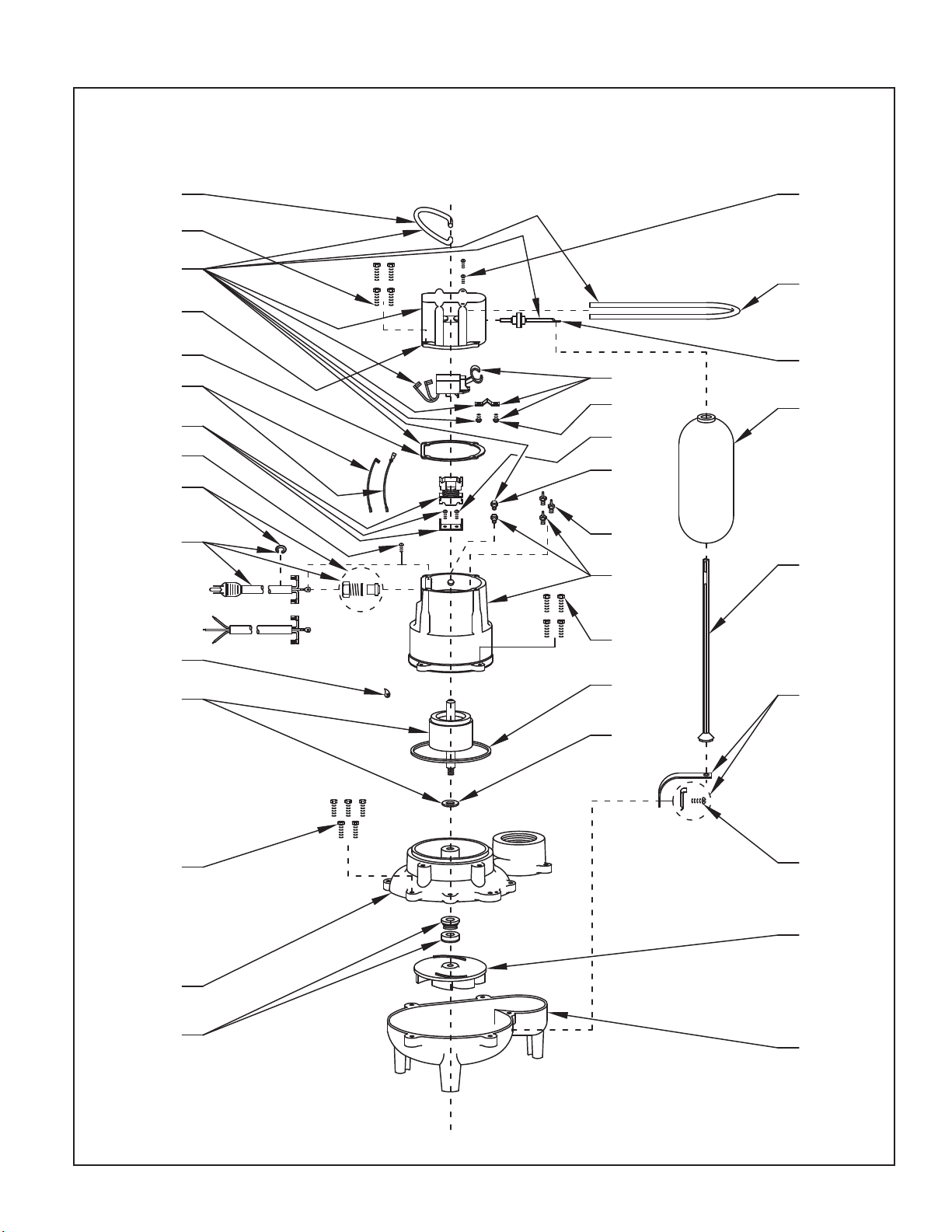
REPLACEMENT PARTS ILLUSTRATION FOR MODELS “M267”, "D267" & “H267”
M267-D267
H267
2
26
1
3
4
6
5
29
9
8
M & D
23
15
H
27
10
11
12
28
13
29
BL
R
25
24
7
14
30
16
22
26
18
19
17
27
20
21
SK132A
© Copyright 2017 Zoeller® Co. All rights reserved.
3
 Loading...