

Zoeller Aquanot 508 Installation Instructions
CAUTION
Product information presented
Your Peace of Mind is Our Top Priority
here reects conditions at time
of publication. Consult factory
regarding discrepancies or
inconsistencies.
®
®
MAIL TO: P.O. BOX 16347 • Louisville, KY 40256-0347
SHIP TO: 3649 Cane Run Road • Louisville, KY 40211-1961
(502) 778-2731 • 1 (800) 928-PUMP • FAX (502) 774-3624
MODEL 508
SECTION: 6.10.073
FM2769
0114
Supersedes
New
visit our web site:
www.zoeller.com
12 VOLT DC BATTERY BACKUP PUMP
INSTALLATION INSTRUCTIONS
PREINSTALLATION CHECKLIST
1. Inspect your pump. Occasionally, products are damaged during shipment. If the unit or any of the parts are damaged, contact your dealer before using.
2. Read all the installation instructions regarding installing and start up. Retain for future reference.
SEE BELOW FOR
LIST OF WARNINGS
1. Testing for Ground. As a safety measure each electrical outlet should
be checked for ground using an Underwriters Laboratory listed circuit
analyzer, which will indicate if the power, neutral and ground wires are
correctly connected to your outlet. If they are not, call a qualied, licensed
electrician.
2. For your protection always disconnect the power supply from its power
source before handling the components of your DC backup pump or the
primary pump.
3. Installation and checking of electrical circuits and hardware should be
performed by a qualied, licensed electrician.
4. All electrical and safety codes must be followed in addition to the National
Electrical Code and all applicable local codes.
5. It is the owner’s responsibility to check the battery and battery
connection at least once a month. Batteries contain acid and
caution must be taken when handling.
6. Risk of electric shock - These pumps have not been investigated
for use in swimming pool areas.
7. According to the state of California (Prop 65), this product contains
chemicals known to the state of California to cause cancer and birth
defects or other reproductive harm.
CAUTION
1. Make sure there is a properly grounded 115V receptacle available. Do
not use primary pump circuit. The location must be within 6' of the control
box and battery. The power supply for your DC control system plugs
directly into the 115V outlet. DO NOT USE AN EXTENSION CORD.
2. Make sure the 115V electrical supply circuit is equipped with fuses or
circuit breakers of proper capacity.
3. DC emergency pumps are designed for handling clear water. Do not use
in septic tanks to pump efuent or sewage pits to pump sewage.
4. Repair and service of your DC backup system should be performed by
an authorized service station.
5. The installation of DC automatic backup pumps requires the use of a
variable level oat switch for operation. It is the responsibility of the
installing party, to ensure that the oat switch will not hang up on the
pump apparatus or pit peculiarities and is secured so the pump will turn
“on” and “off”. It is recommended that the pit be 18" in diameter or larger
to accommodate both a primary and a DC backup pump.
Turbulence caused by high velocity incoming water
can cause the DC pump to airlock. If this condition exists, the
incoming water must be bafed to avoid excessive turbulence.
SEE BELOW FOR
LIST OF CAUTIONS
P/N 152520
REFER TO WARRANTY ON PAGE 2.
© Copyright 2014 Zoeller Co. All rights reserved.

LIMITED WARRANTY
CAUTION
Manufacturer warrants, to the purchaser and subsequent owner during the
warranty period, every new product to be free from defects in material and
workmanship under normal use and service, when properly used and maintained,
for a period of one year from date of purchase by the end user, or 18 months
from date of original manufacture of the product, whichever comes rst. Parts
that fail within the warranty period, one year from date of purchase by the
end user, or 18 months from the date of original manufacture of the product,
whichever comes rst, that inspections determine to be defective in material or
workmanship, will be repaired, replaced or remanufactured at Manufacturer's
option, provided however, that by so doing we will not be obligated to replace
an entire assembly, the entire mechanism or the complete unit. No allowance
will be made for shipping charges, damages, labor or other charges that may
occur due to product failure, repair or replacement.
This warranty does not apply to and there shall be no warranty for any
material or product that has been disassembled without prior approval of
Manufacturer, subjected to misuse, misapplication, neglect, alteration, accident
or uncontrollable act of nature; that has not been installed, operated or
maintained in accordance with Manufacturer's installation instructions; that has
been exposed to outside substances including but not limited to the following:
sand, gravel, cement, mud, tar, hydrocarbons, hydrocarbon derivatives (oil,
Note: The purchase of an Aquanot® Battery from Zoeller Pump Company will extend the Limited Warranty to three years from date of installation.
Note: Three year limited warranty valid only when a complete system is purchased and used as a backup to a primary dewatering system. A complete system
includes a Model 508 and an Aquanot® Battery.
gasoline, solvents, etc.), or other abrasive or corrosive substances, wash towels
or feminine sanitary products, etc. in all pumping applications. The warranty
set out in the paragraph above is in lieu of all other warranties expressed or
implied; and we do not authorize any representative or other person to assume
for us any other liability in connection with our products.
Contact Manufacturer at, 3649 Cane Run Road, Louisville, Kentucky 40211,
Attention: Customer Support Department to obtain any needed repair or
replacement of part(s) or additional information pertaining to our warranty.
MANUFACTURER EXPRESSLY DISCLAIMS LIABILITY FOR SPECIAL,
CONSEQUENTIAL OR INCIDENTAL DAMAGES OR BREACH OF
EXPRESSED OR IMPLIED WARRANTY; AND ANY IMPLIED WARRANTY
OF FITNESS FOR A PARTICULAR PURPOSE AND OF MERCHANTABILITY
SHALL BE LIMITED TO THE DURATION OF THE EXPRESSED WARRANTY.
Some states do not allow limitations on the duration of an implied warranty, so
the above limitation may not apply to you. Some states do not allow the exclusion
or limitation of incidental or consequential damages, so the above limitation or
exclusion may not apply to you.
This warranty gives you specic legal rights and you may also have other rights
which vary from state to state.
MAINTENANCE
1. Inspect and test the system for proper operations at least every 3 months.*
(a) Red power on indicator light should be “on” indicating AC power is
on.
(b) Unplug primary pump and the control charger from power supply.
(c) Fill sump with water to the “on” level for the DC pump. Allow pump
to run a few minutes.
(d) The alarm will sound approximately 3 seconds after the pump starts
to run.
(e) Push alarm reset switch. The alarm will go “off”.
(f) Pump will shut off after water level is lowered and the oat drops
to the off position.
2. Plug the control charger and the primary pump into the wall outlet.
(a) The primary pump will come on and lower the water to the
normal operating level and shut off.
(b) The “yellow” charging light should be on. The charger is replacing
the energy consumed during the test. The “green” light will come on
after the charger has replaced the energy consumed during the test.
*Wet cell batteries should be checked every month.
TROUBLESHOOTING INFORMATION
1. DC Pump won’t run.
(a) Check 30 amp fuse in line from pump to switch (see g. 3). If fuse
is blown, replace with 30 amp Littelfuse type 3AG, series 311.
(b) Check for proper connections.
(c) Check all wire terminal points. Clean if required.
(d) Check for low battery. Service battery if required.
2. Pump runs but pumps very little or no water.
(a) Check for low battery. Battery will recharge if Red power “on”
light indicates power has been restored and the oat switch is
in the off position.
(b) If immediate usage is required, remove and replace dead
battery with a full recharged battery.
(c) Due to varying conditions the pump may continue to run on a
low battery without sufcient power to remove water. Pump will
not stop running until battery is completely discharged.
(d)
not store sufcient energy for full service. A weak recharged
battery can only be detected by reduced pumping time or by
professional load testing equipment. If your emergency pump
system is used frequently the battery should be checked by a
qualied battery dealer.
3. Pump cycles too frequently.
(a) Check positions of rubber stops on oat rod.
(b) Adjust upper rubber oat stop as required. Recommended for
standard installation.
Weak batteries can be recharged but may
4. Float switch in “on” position. Pump won’t run.
(a) Remove pump. Check for obstruction in pump preventing
impeller from rotating.
5. Pump runs, but pumps water intermittently.
(a) Pump is air locking. Check ow of water incoming to sump. If
water is entering the sump at a high velocity creating a turbulent
condition, a mixture of air and water may cause a complete
or partial air lock and reduce or stop the ow of water in the
discharge pipe.
(b) Bafe the incoming stream of water to reduce turbulence.
Diverting water stream against wall of basin usually corrects an
air lock problem.
6. Water level stays high. DC Pump continues to run.
(a) Battery is low.
(b) If power has been restored and water in sump remains high check
primary pump. Service if required.
(c) After several hours the battery will be restored to full charge.
7. Alarm sounds during battery recharge cycle.
(a) To silence alarm if alarm will not reset, unplug the charger from
115V wall outlet, then disconnect the black lead from charger on
negative (-) battery post. Check battery. Replace if necessary.
Reconnect and refer to Installation (step 12).
© Copyright 2014 Zoeller Co. All rights reserved.
2
DESCRIPTION
The DC emergency pump is
designed as a backup to your
primary sump pump during
unexpected power outages or
primary pump failure. The DC
pump, electronic controls and all
the parts required for installation
are included except the battery
which is supplied by the user. The
system is designed for installation
in sumps with minimum of 18"
diameter and 24" deep. For 18" x
22" applications, consult factory.
4
1
11
6
9
2
10
8
5
3
7
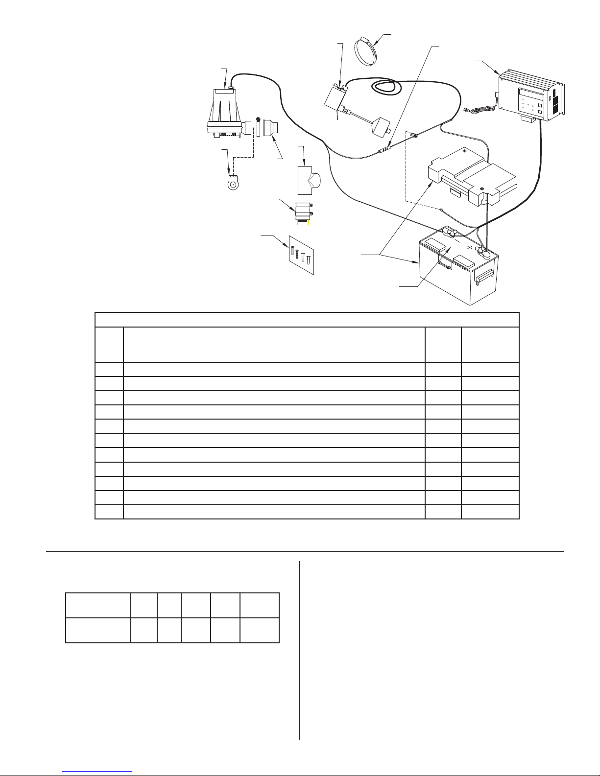
Item Description Qty
1 Pump 12V DC / Backup (Service Part) 1 152962
2 Fitting, PVC 1.5" Tee / Sch 40 / (Pressure Fitting) 1 005645
3 Fuse, 250V / Agc-30 1 012353
4 Switch, Float / Vert Master 1 017197
5 Clamp, #28 Worm-SS (Float Switch) 1 012724
6 Valve, Check / 1.5 Inline / Vertical 1 019768
7 Charger, DC Asm / Switch Mode 1 153000
8 Battery Box Asm (Box and Cover) 1 10-0764
9 Hardware Pak, Charger / Switch Mode 1 152864
10 Fitting, Asm & Clamp "508" (Service part) 1 152969
11 Flapper Asm, (Service part) 1 152970
PERFORMANCE
The DC pump performance with fully charged 12V battery
Discharge
Feet of Head
Flow
Gal. per min.
The DC controller is equipped with a 10 amp charger for maintaining the
battery in a ready state and recharging the battery after use when AC power
is restored. Time for recharge depends upon the amount of power consumed
by the pumping cycle during the AC power interruption. The pump may go
back to the ready run position in a very short period of time. A completely
drained battery may require up to 24 hours for full recharge. If battery does
not charge properly, the LCD will display BATFAIL and alarm will sound.
5 10 15 20 22
39 30 20 6
Shut-off
Head
12 VOLT BAT TERY
SUPPLIED BY USER
SK3008
Model 508
508-A
01/14
thru Current
BATTERY SELECTION
The DC emergency pump system requires a good quality, 12 volt battery to
obtain maximum pumping time during a power outage. A deep-cycle, 12 volt,
105 amp-hour marine battery or larger is recommended and will provide approximately 6 hours of continuous pumping time in a sump pump installation
with 8' of head pressure. In most installations the pump runs intermittently
and the battery life is extended accordingly. Batteries with top terminals are
recommended for ease of installation. "Wet" cell batteries contain acid and
proper precaution must be taken when handling. Maximum battery size 13½"
Length x 7" Width x 9½" Height.
© Copyright 2014 Zoeller Co. All rights reserved.
3
 Loading...