How it Works
Log In / Sign Up
Buy Points
How it Works
FAQ
Contact Us
Questions and Suggestions
Users
Zoeller
Loading...
#
49
53
57
98
104
105
2
110
115
120
131
132
137
151
152
153
264
266
267
268
340
503
2
508
9
580
585
611
2
621
2
631
2
641
2
651
2
661
2
820
4290
4291
6111
6120
6121
6122
6123
6124
6355
1043-006
462-0006
1073-0001
1075-0001
A
Aquanot 508
AQUANOT 580
AQUANOT 585
AqyaNot 508 Active
B
BA293
BAX6111
BAX6112
BAX6113
BAX6120
BAX6121
BAX6122
BAX6123
BAX6124
BAX6125
BE266
BE267
BE268
BN266
BN267
BN268
D
D266
D267
2
D268
D293
Deep Well
E
E266
E267
2
E268
E293
EX6111
Loading...
Loading...
Nothing found
508
Control Charger
1 pgs
339.98 Kb
0
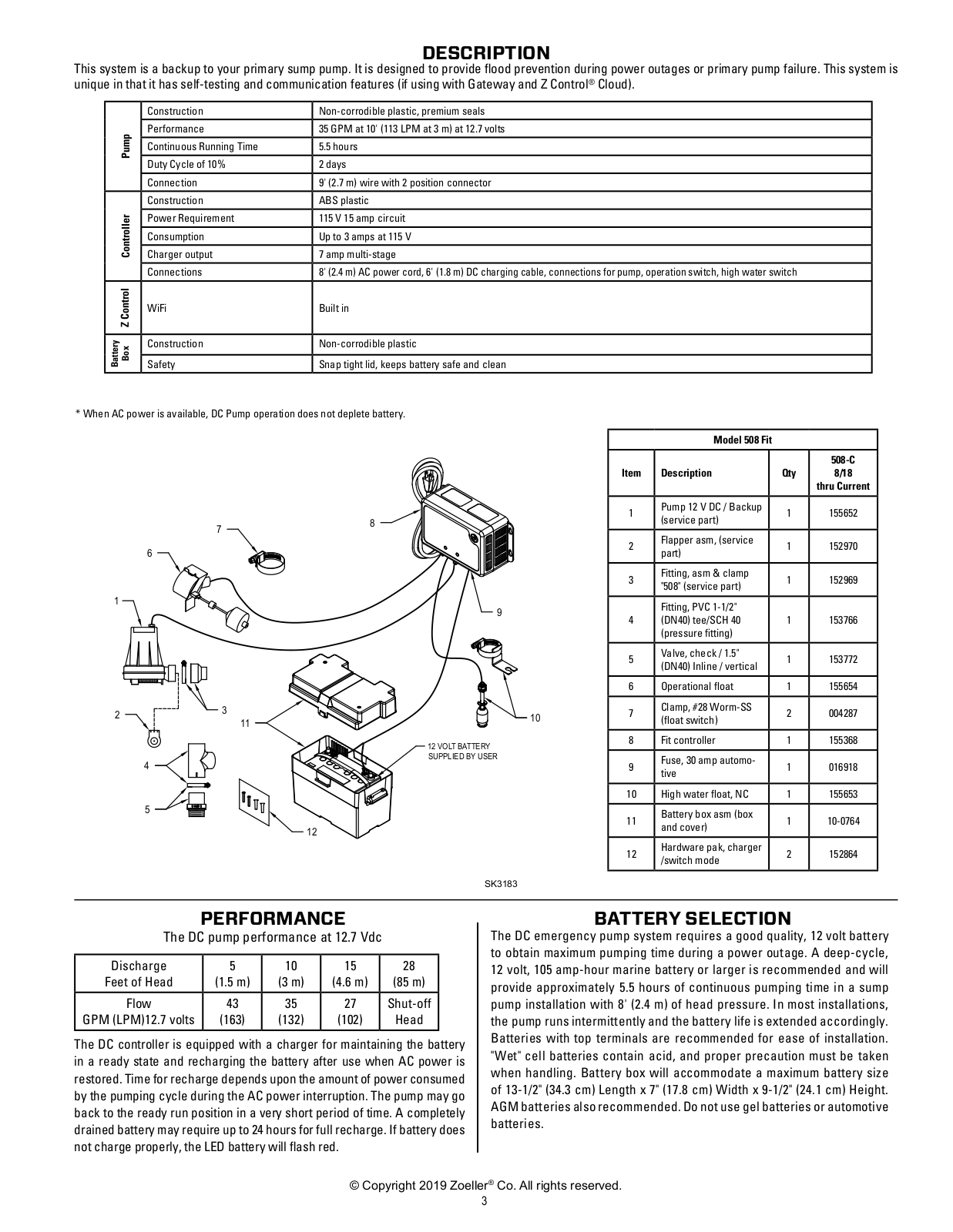
Exploded View
1 pgs
198.57 Kb
0
Float Switch
1 pgs
177.82 Kb
0
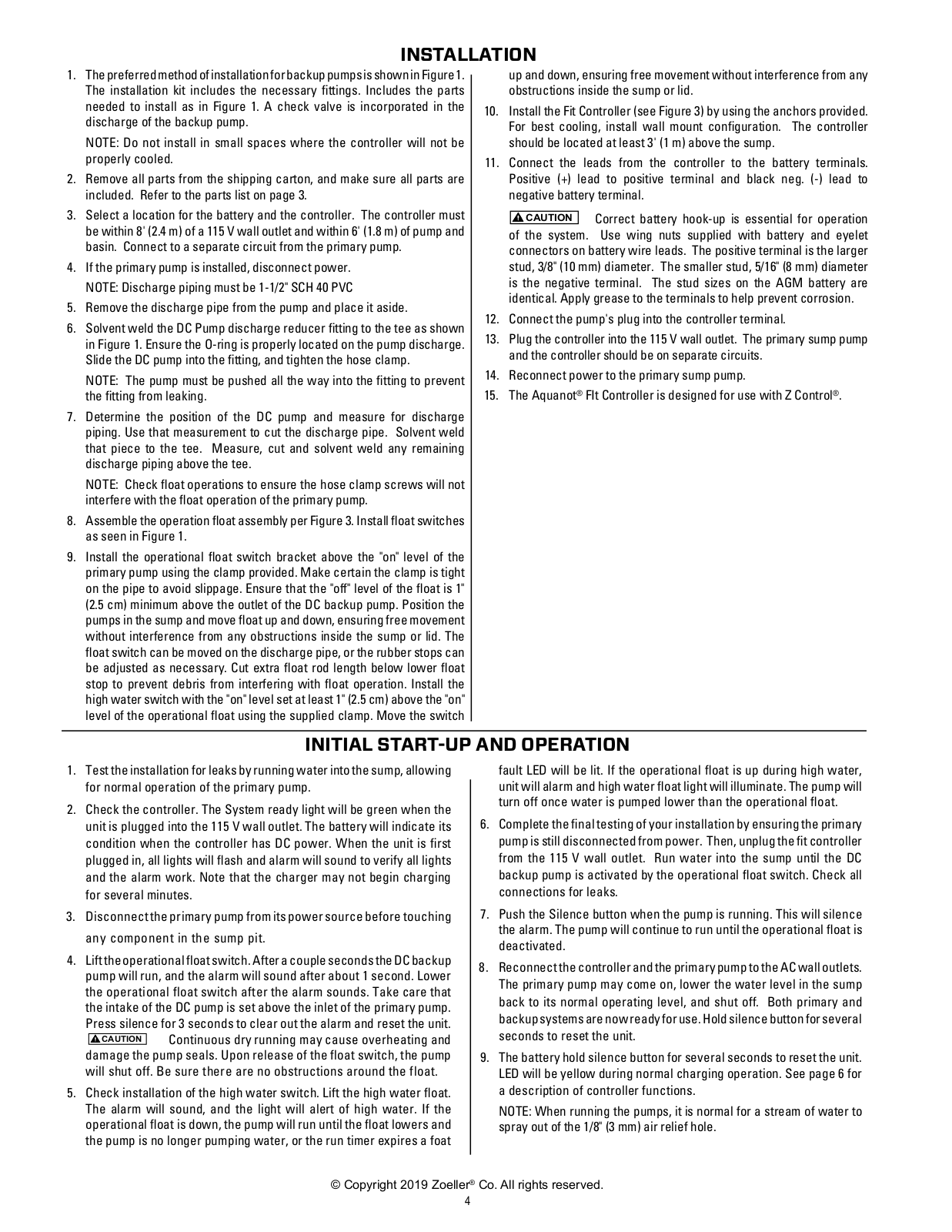
Installation Diagram
1 pgs
1.19 Mb
0
Installation Guide
12 pgs
1.2 Mb
0
Installed System
1 pgs
323.32 Kb
0
Parts System
1 pgs
324.57 Kb
0
Performance Curve
1 pgs
460.47 Kb
0
Specification Sheet
2 pgs
491.42 Kb
0
Table of contents
Loading...
Zoeller 508 Installation Guide
...
Zoeller Installation Guide
Download
Specifications and Main Features
Frequently Asked Questions
User Manual
Download
Loading...
+
8
hidden pages
Unhide
You need points to download manuals.
1 point = 1 manual.
You can buy points or you can get point for every manual you upload.
Buy points
Upload your manuals