

Page 1
SJN-960
Videoregistratore Time Laps
Time Laps Videorecorder
Manuale D’uso
Users Manual
Page 2
1
Manuale d’uso
User’s manual
SICUREZZA
Il lampo con la punta a forma di freccia all’interno di un triangolo equilatero ha lo scopo di
segnalare all’utente la presenza di una tensione pericolosa non isolata all’interno
dell’apparecchio, tale da rappresentare un pericolo di scosse elettriche.
Il punto esclamativo all’interno di un triangolo equilatero ha lo scopo di segnalare all’utente che il
manuale d’uso che accompagna l’apparecchio contiene istruzioni importanti riguardo al
funzionamento e alla manutenzione.
PRECAUZIONI IMPORTANTI
Oltre all’attenzione particolare dedicata agli standard qualitativi durante la produzione del presente
apparecchio video, la sicurezza è uno degli aspetti principali nella progettazione di ogni dispositivo. Tuttavia
anche l’utente è responsabile della sicurezza. Il presente manuale elenca informazioni importanti che
consentono all’utente di sfruttare e utilizzare correttamente il presente apparecchio video e gli accessori.
Leggere attentamente queste informazioni prima di accendere e utilizzare il presente apparecchio video.
INSTALLAZIONE
1. Leggere e seguire le istruzioni: prima di utilizzare l’apparecchio video, leggere tutte le istruzioni
riguardanti la sicurezza e il funzionamento. Rispettare tutte le istruzioni relative al funzionamento.
2. Conservare le istruzioni: conservare le istruzioni riguardanti la sicurezza e il funzionamento per
riferimenti futuri.
3. Tenere conto degli avvertimenti: rispettare tutti gli avvertimenti presenti sull’apparecchio video e
tutte le istruzioni relative al funzionamento.
4. Polarizzazione: il presente apparecchio video è provvisto di una spina di linea a corrente alternata
polarizzata (una spina che presenta uno spinotto piatto più ampio dell’altro). Questa spina si adatta
Page 3

2
alla presa di corrente solo in un modo. Si tratta di una caratteristica di sicurezza: qualora l’utente
non riesca a inserire completamente la spina nella presa, capovolgere la spina. Se questo non
bastasse, rivolgersi all’elettricista perché sostituisca la presa di corrente obsoleta. Per evitare
scosse elettriche, utilizzare la presente spina polarizzata con una prolunga, con un connettore fisso
o con un’altra presa solo se lo spinotto piatto può essere completamente inserito. Se all’utente
occorre una prolunga, utilizzare un cavo polarizzato.
5. Alimentazione: utilizzare il presente apparecchio video solo con il tipo di alimentazione indicato
sulla piastra delle indicazioni. Qualora l’utente non fosse certo del tipo di alimentazione disponibile,
contattare il rivenditore o la società per la fornitura elettrica locale. Per i prodotti video che
funzionano a batterie o con altre sorgenti, consultare il manuale d’uso.
6. Sovraccarico: per evitare incendi e scosse elettriche, non sovraccaricare la prolunga. Prese e
prolunghe AC sovraccaricate, cavi di alimentazione logorati, materiale isolante danneggiato o
crepato e spine rotte sono pericolosi e possono causare incendi e scosse elettriche. Esaminare
periodicamente il cavo e se si rilevano danni o il materiale isolante appare deteriorato, contattare
un tecnico perché lo sostituisca.
7. Protezione del cavo di alimentazione: posizionare il cavo di alimentazione di modo che non venga
calpestato e che gli elementi posti sopra o contro di esso non lo schiaccino. Prestare particolare
attenzione alla parte di cavo vicino alla spina, ai connettori fissi di comodità e al punto di
connessione con l’apparecchio video.
8. Ventilazione: la ventilazione è affidata alle fessure e alle aperture presenti sull’involucro affinché
l’apparecchio video funzioni correttamente e non si surriscaldi. Tali aperture non devono essere
bloccate o coperte. Non collocare l’apparecchio video su un letto, un divano, un tappeto o su
superfici simili per evitare di bloccare le aperture. Non collocare il presente apparecchio video
sopra o vicino a radiatori o a valvole di regolazione del calore. Collocare il presente apparecchio
video su un supporto a muro come una libreria o un rack solo se è garantita una ventilazione
adeguata e dopo aver seguito le istruzioni del produttore.
9. Accessori: per evitare pericoli utilizzare solo gli accessori consigliati dal produttore del presente
apparecchio video.
10. Acqua e umidità: non utilizzare il presente apparecchio video vicino all’acqua, per esempio vicino a
una vasca da bagno, a un lavabo, a un lavandino o una tinozza per lavare la biancheria, in un
seminterrato umido, o vicino a una piscina e simili. Attenzione: garantire la sicurezza elettrica. Sui
dispositivi o sugli accessori collegati al presente apparecchio e alimentati dalla rete di linea deve
essere presente il marchio UL o la certificazione CSA e non devono essere modificati a scapito
della sicurezza. In questo modo è possibile eliminare tutti I potenziali pericoli di incendi e scosse
elettriche. Qualora sorgessero dubbi, contattare personale qualificato.
11. Accessori: collocare l’apparecchio video su carrelli, sostegni, supporti a tre gambe, mensole o
tavoli saldi. In caso contrario, l’apparecchio video potrebbe cadere ferendo bambini e adulti o
danneggiarsi gravemente. Collocare il presente apparecchio video solo su carrelli, sostegni,
supporti a tre gambe, mensole o tavoli consigliati dal produttore oppure venduti con l’apparecchio
video. Montare l’apparecchio seguendo le istruzioni del produttore e utilizzare solo gli apparecchi
consigliati dal produttore.
12. Una volta collocato su un carrello, spostare l’apparecchio con particolare attenzione. L’apparecchio
video e il carrello si potrebbero rovesciare a causa di brusche fermate, una forza eccessiva o una
superficie irregolare.
13. Linee di alimentazione: non collocare un’antenna esterna nelle vicinanze di linee di alimentazione
aeree, altri circuiti luminosi elettrici o di alimentazione o in zone in cui potrebbe cadere su tali linee
o circuiti di alimentazione. Durante l’installazione di un’antenna esterna, prestare estrema
attenzione per evitare di entrare in contatto con linee o circuiti di alimentazione. Tale contatto
potrebbe risultare mortale. L’installazione di un’antenna all’aperto può essere pericolosa: contattare
un antennista.
UTILIZZO
14. Pulizia: scollegare l’apparecchio video dalla presa a muro prima di pulirlo. Non utilizzare detergenti
liquidi o detergenti aerosol. Utilizzare un panno umido per la pulizia.
15. Penetrazione di oggetti e liquidi: per evitare incendi o scosse elettriche, non introdurre oggetti di
alcun tipo all’interno del presente apparecchio video attraverso le aperture poiché potrebbero
toccare punti con una tensione pericolosa o parti “esposte”. Non versare liquidi di alcun tipo
sull’apparecchio video.
16. Temporali: per proteggere maggiormente l’apparecchio video durante un temporale o quando
l’apparecchio rimane incustodito e inutilizzato per periodi prolungati, scollegarlo dalla presa a muro
Page 4

3
e scollegare l’antenna o il cavo per evitare che l’apparecchio video si danneggi a causa dei lampi o
del sovraccarico transitorio della linea di alimentazione.
RIPARAZIONI
17. Riparazioni: non cercare di riparare l’apparecchio video, aprire o rimuovere i coperchi per non
esporsi a tensione pericolosa o ad altri pericoli. Per le riparazioni rivolgersi a personale qualificato.
18. Condizioni in cui occorrono interventi di riparazione: scollegare l’apparecchio video dalla presa a
muro e contattare personale qualificato se si riscontrano le seguenti condizioni.
A. Il cavo o la spina di alimentazione sono danneggiati.
B. All’interno dell’apparecchio video sono penetrati oggetti o sostanze liquide.
C. L’apparecchio video è stato esposto a pioggia o acqua.
D. L’apparecchio video non funziona normalmente anche se l’utente segue le istruzioni d’uso. Regolare
solo quei controlli descritti dalle istruzioni d’uso. Una regolazione errata degli altri controlli può
causare danni e richiedere lavoro supplementare a un tecnico qualificato per ripristinare il
funzionamento normale dell’apparecchio video.
E. L’apparecchio video è caduto, il telaio è stato danneggiato.
F. Le prestazioni dell’apparecchio video sono notevolmente variate: è necessario un intervento di
riparazione.
19. Pezzi di ricambio: qualora fosse necessario sostituire alcune parti, contattare un tecnico e
verificare che i pezzi di ricambio abbiano le stesse caratteristiche di sicurezza dei pezzi originali.
Utilizzare i pezzi di ricambio descritti dal produttore per evitare incendi, scosse elettriche o altri
pericoli.
20. Controllo della sicurezza: una volta ultimati gli interventi di manutenzione o riparazione, chiedere al
tecnico di verificare la sicurezza come richiesto dal produttore per determinare che il
funzionamento dell’apparecchio video sia sicuro.
21. Montaggio a muro o a soffitto: montare il presente apparecchio a muro o a soffitto solo seguendo le
indicazioni del produttore.
22. Calore: collocare il presente apparecchio lontano da fonti di calore come radiatori, valvole di
regolazione del calore, stufe o altri prodotti (inclusi gli amplificatori) che producono calore.
INFORMAZIONI PER L’UTENTE
Questo prodotto è stato esaminato ed è risultato conforme ai valori massimi previsti per gli dispositivi digitali
di Classe B, secondo quando stabilito alla sezione 15 delle Norme FCC. L’obiettivo di questi valori massimi
previsti è fornire una protezione adeguata contro le interferenze dannose nel caso di installazioni
residenziali. Il presente apparecchio genera, utilizza e può irradiare energia di radiofrequenza e, se non è
installato e utilizzato secondo le istruzioni, può causare interferenze dannose alle comunicazioni radio.
Tuttavia non è possibile garantire l’assenza di interferenze all’interno di installazioni particolari. Qualora il
presente apparecchio causi interferenze dannose alla ricezione di radio e TV, rilevabili con l’accensione e lo
spegnimento dell’apparecchio, l’utente è tenuto a cercare di correggere tali interferenze ricorrendo alle
seguenti misure:
- orientare o posizionare diversamente l’antenna ricevente;
- aumentare la distanza tra l’apparecchio e il ricevitore;
- collegare l’apparecchio a una presa appartenente a un circuito diverso da quello cui è collegato il
ricevitore;
- rivolgersi al rivenditore o a un tecnico radio/TV esperto.
AVVERTIMENTO
Modiche o variazioni non espressamente approvate dal produttore possono annullare l’autorizzazione
dell’utente a utilizzare l’apparecchio.
Page 5

4
Indice
Posizione dei controlli e degli indicatori..............................................................................................5
Pannello frontale..............................................................................................................................5
Posizione dei controlli e degli indicatori (opzionali)...........................................................................6
Pannello frontale..............................................................................................................................6
Pannello posteriore...........................................................................................................................2
Telecomando....................................................................................................................................3
Videocassette.......................................................................................................................................4
Tipi di on-screen display e successione degli OSD.............................................................................5
Impostazione dell’orologio..................................................................................................................6
Accesso ai vari on-screen display (OSD)............................................................................................7
Registrazione normale..........................................................................................................................9
Programmazione della registrazione con timer..................................................................................10
Registrazione degli eventi di allarme.................................................................................................12
Registrazione one-shot (singola immagine).......................................................................................13
Registrazione con collegamento (serie).............................................................................................14
Registrazione continua automatica....................................................................................................15
Riproduzione normale........................................................................................................................15
Riproduzione normale....................................................................................................................15
Controllo Tracking.........................................................................................................................16
Riproduzione audio........................................................................................................................16
Riproduzione speciale........................................................................................................................16
Ricerca delle immagini..................................................................................................................16
Fermo immagine............................................................................................................................16
Controllo blocco verticale..............................................................................................................17
Rallentatore....................................................................................................................................17
Controllo della registrazione..........................................................................................................17
Ricerca degli eventi di allarme.......................................................................................................17
Analisi degli eventi di allarme.......................................................................................................18
Ricerca degli indici........................................................................................................................18
Altre funzioni.....................................................................................................................................18
Contatore del nastro (ricerca zero).................................................................................................18
Impostazione del blocco di sicurezza (Impostazione del blocco)..................................................19
Impostazione del segnalatore acustico...........................................................................................20
Impostazione della modalità video................................................................................................20
Controllo del numero di eventi di allarme registrati......................................................................21
Controllo della memoria degli episodi in cui è mancata la corrente..............................................21
Controllo della durata di utilizzo...................................................................................................21
Controllo giornaliero..........................................................................................................................23
Guida alla ricerca e all’eliminazione dei guasti.................................................................................25
Dati.....................................................................................................................................................27
Page 6
5
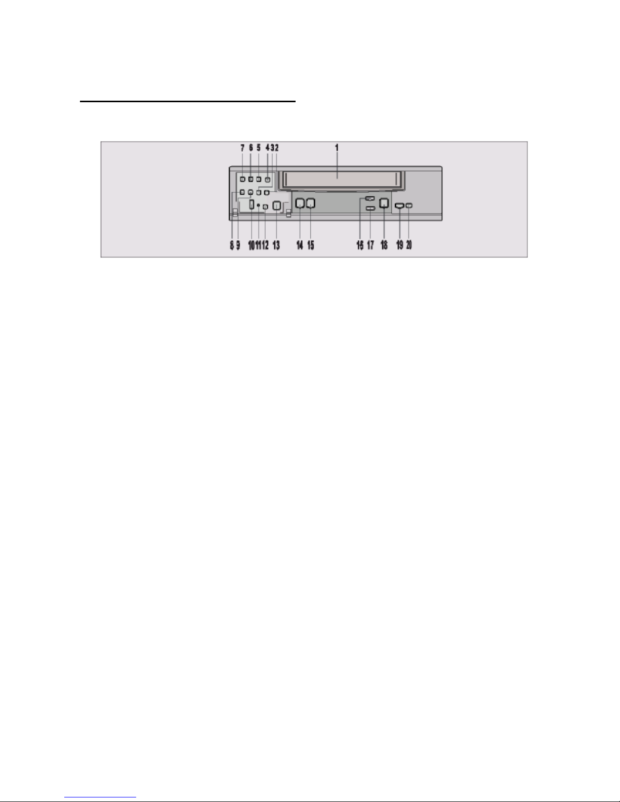
Posizione dei controlli e degli indicatori
Pannello frontale
1. Apertura per l’inserimento della cassetta.
2. Tasto Velocità di registrazione/riproduzione (▲) (SET + tasto).
3. Tasto Velocità di registrazione/riproduzione (▼) (SET – tasto).
4. Tasto Controllo registrazione.
5. Tasto Display.
6. Tasto Audio attivo.
7. Tasto Menu.
8. Tasto Shift (▼) (spostamento) / Tracking (-).
9. Tasto Shift (►) (spostamento) / Tracking (+).
10. Commutatore per bloccare il telecomando.
11. Commutatore Blocco.
12. Tasto Reset (reimposta).
13. Tasto Pausa/Fermo immagine.
14. Tasto Accensione/Timer.
15. Tasto REC (registra).
16. Tasto Stop/espulsione della cassetta.
17. Tasto Contatore.
18. Tasto Cancella.
19. Tasto Play (riproduci).
20. Tasto REW (riavvolgi) (lento -): consultare la relativa sezione.
21. Tasto FF (avanti veloce) (lento +): consultare la relativa sezione.
Page 7

6
Posizione dei controlli e degli indicatori (opzionali)
Pannello frontale
1. Apertura per l’inserimento della cassetta.
2. Tasto Velocità di
registrazione/riproduzione (▲) (SET +
tasto).
3. Tasto Velocità di
registrazione/riproduzione (▼) (SET –
tasto).
4. Tasto Controllo registrazione.
5. Tasto Display.
6. Tasto Audio attivo.
7. Tasto Menu.
8. Tasto Shift (▼) (sposta) / Tracking (-).
9. Tasto Shift (►) (sposta) / Tracking (+).
10. Commutatore per bloccare il
telecomando.
11. Commutatore Blocco
12. Tasto Reset (reimposta).
13. Tasto Pausa/Fermo immagine.
14. Tasto Accensione/Timer.
15. Tasto REC (registra).
16. Tasto Stop/espulsione della cassetta.
17. Tasto Contatore.
18. Tasto Cancella.
19. Tasto Play (riproduci).
20. Tasto F. ADV: consultare la relativa
sezione.
21. Commutatore: consultare la relativa
sezione.
Page 8

Fermo
immagine
Rallentatore 1
Rallentatore 2
Rallentatore 3
Riproduzione
Avanti 1
Avanti 2
Indietro 1
Indietro 2
UTILIZZO DEL COMMUTATORE
Il commutatore è il selettore esterno. Quando il VCR è in modalità STOP, se l’utente ruota il commutatore
verso sinistra o verso destra e lo rilascia, il VCR attiva la funzione REWIND (riavvolgi) o FAST FORWARD
(avanti veloce). Quando è attiva la modalità REWIND (riavvolgi) o FAST FORWARD (avanti veloce), l’utente
può ruotare e tenere il commutatore per accedere alla modalità LOGIC SEARCH (ricerca logica). Rilasciare
il commutatore per tornare alla modalità REWIND (riavvolgi) o FAST FORWARD (avanti veloce).
MODALITÀ FERMO IMMAGINE
Quando è attiva la funzione fermo immagine, l’utente può visualizzare il video a velocità diverse, anche al
rallentatore, ruotando e posizionando il commutatore su diversi punti. La figura a destra descrive le opzioni
previste secondo la posizione in cui si trova il commutatore. Il VCR torna in modalità fermo immagine
quando l’utente rilascia il commutatore.
CARATTERISTICHE DEL COMMUTATORE
- Modalità fermo immagine: ruotare avanti o indietro il commutatore per regolare la velocità da lenta a ricerca
(riproduzione normale, riproduzione a velocità doppia).
- Modalità stop: ruotare e rilasciare il commutatore per riavvolgere o far avanzare velocemente il nastro.
- Modalità di riproduzione normale: ruotare il commutatore avanti per attivare la riproduzione a velocità
doppia e la ricerca in avanti (la stessa funzione può essere attivata ruotando all’indietro il commutatore).
Page 9
1
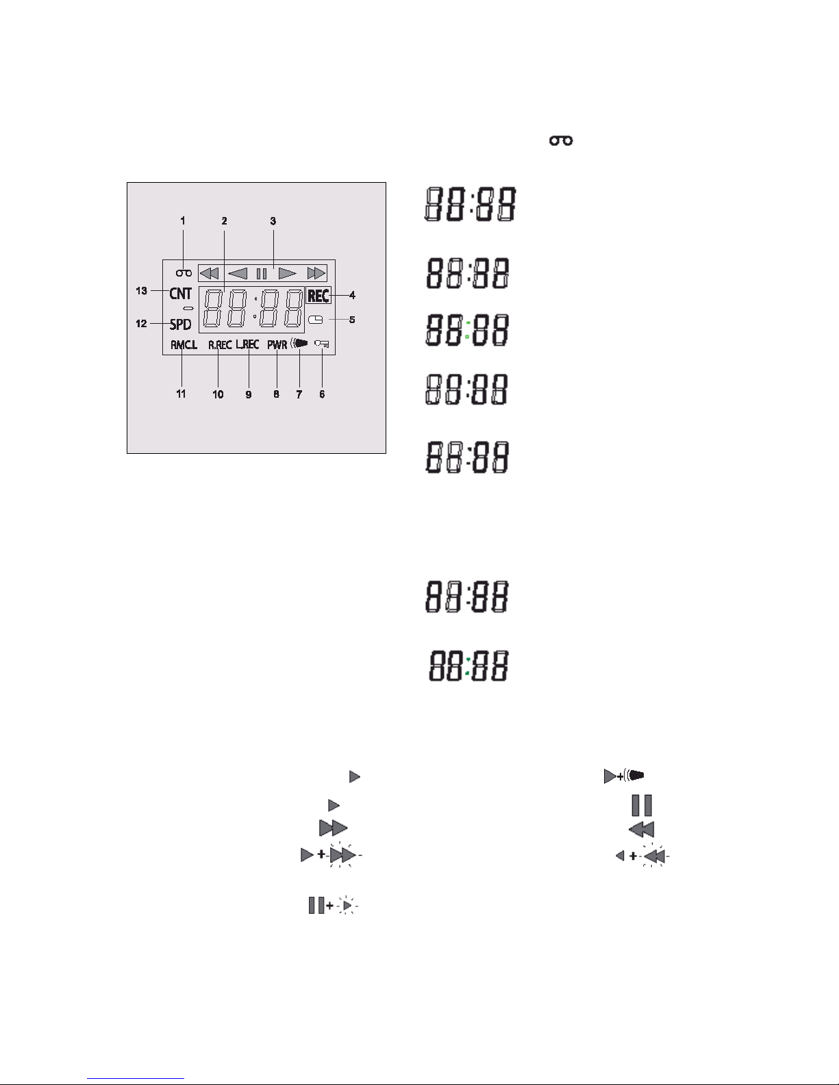
Schema dei LED digitali
1. Indicatore Cassetta:
Appare quando è stata inserita una cassetta.
2. Modalità Display.
Contatore (es. 10: ore, 59:
minuti); valore massimo per le
ore: 19 - valore massimo per i
minuti: 59
Contatore eventi di allarme
(es. A: allarme, 32: allarme
n.°)
Velocità di riprod./registr. (es.
960H: velocità di
riprod./registr.)
Orario (es. 7: ora, 07: minuti)
Errore (es. E: errore, 02: errore
n.°)
- E-01: non è possibile inserire la
cassetta o non è stata inserita
alcuna cassetta.
- E-02: la cassetta si ferma.
- E-03: il tamburo di avvolgimento
non ruota correttamente.
- E-04: il nastro è tagliato/rotto.
Audio attivo (es. A: audio,
18H: velocità di riproduzione)
Registrazione one-shot
1. Indicatori di funzionamento
Visualizzano la modalità di funzionamento reale.
Modalità di
funzionamento
Indicatore
Modalità di
funzionamento
Indicatore
Registrazione (REC)
REC +
Registrazione eventi di
allarme
+ REC
Riproduzione (play)
Fermo immagine / pausa
Avanti veloce (FF)
Riavvolgi (REW)
CUE
Rivedi (REVIEW)
Lenta
(pausa fermo
immagine + FF, pausa
fermo immagine +
REW)
2. Indicatore controllo registrazione: REC
Lampeggia durante il controllo registrazione.
Page 10

2
3. Indicatore registrazione con timer:
Appare quando il VCR è in modalità stand-by registrazione con timer oppure durante una registrazione
con timer.
4. Indicatore SET LOCK SW:
Appare quando SET LOCK SW (commutatore blocco impostazioni) è impostato su “ON”.
5. Indicatore evento di allarme:
Lampeggia quando viene registrato un evento di allarme e smette di lampeggiare una volta terminata la
registrazione dell’evento di allarme.
6. Indicatore PWR: PWR
Indica che il VCR è acceso.
7. Indicatore L.REC: L.REC
Appare quando nel menu la registrazione con collegamento è impostata su “YES”.
8. Indicatore R.REC: R.REC
Appare quando nel menu la registrazione continua è impostata su “YES”.
9. Indicatore RMC.L: RMC.L
Appare quando RMC LOCK SW (commutatore blocco telecomando) è impostato su “ON”.
10. Indicatore SPD: SPD
Indica la velocità di registrazione sul nastro.
11. Indicatore CNT: CNT
Indica la relativa posizione sul nastro.
Pannello posteriore
1. Corrente AC
2. Jack ingresso microfono (opzionale)
3. Jack uscita video
4. Jack ingresso video
5. Jack uscita audio
6. Jack ingresso audio
7. Morsetto registrazione one-shot
8. Morsetto fine nastro
9. Morsetto uscita attivazione
10. Morsetto uscita collegamento
11. Morsetto ingresso collegamento
12. Morsetto uscita allarme
13. Morsetto ingresso allarme
14. Morsetto messa a terra
Page 11
3
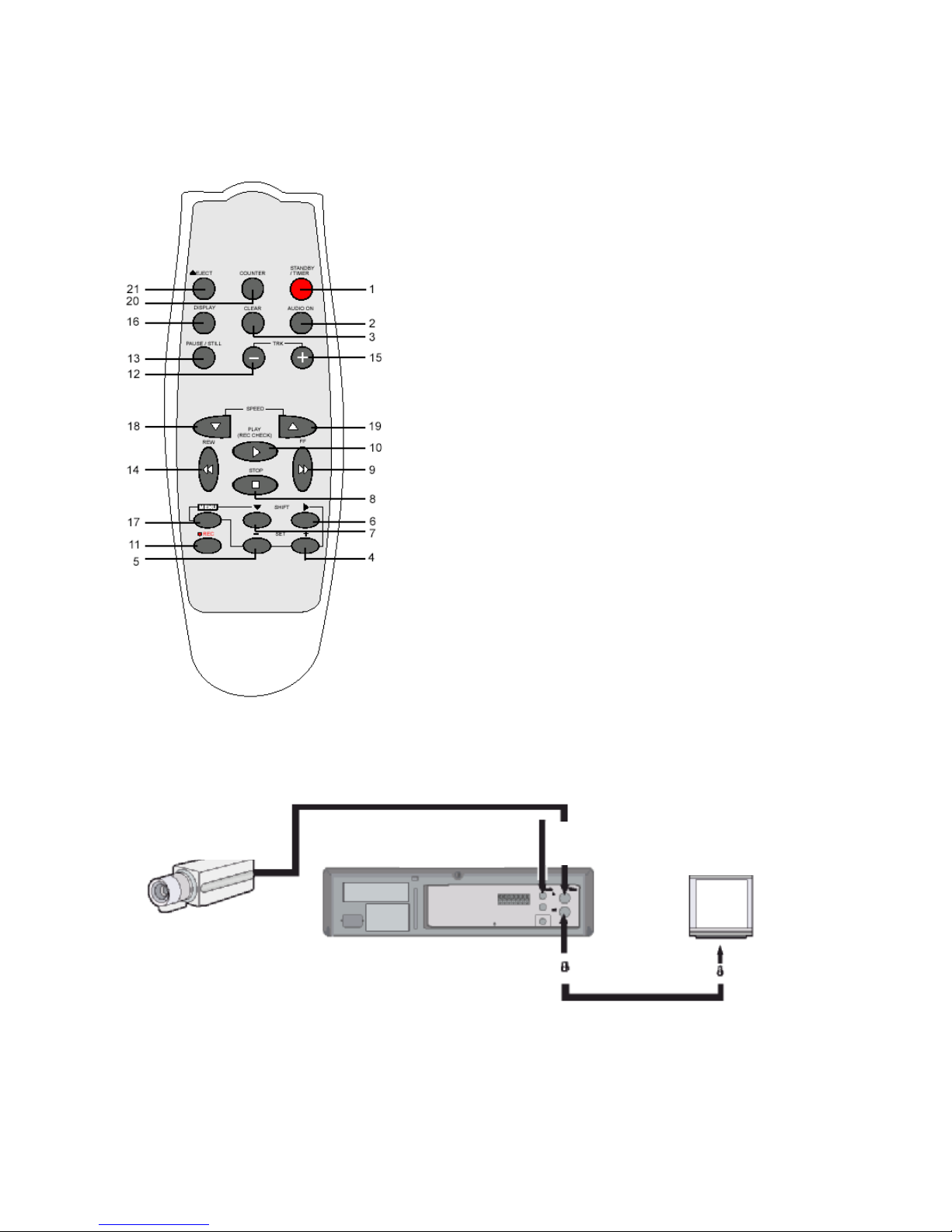
Telecomando
1. Tasto accensione/timer
2. Tasto audio attivo
3. Tasto cancella
4. SET + tasto
5. SET– tasto
6. Tasto Shift ► (sposta) (sposta il cursore o permette di
selezionare)
7. Tasto Shift ▼ (sposta) (sposta il cursore o permette di
selezionare)
8. Tasto Stop ■
9. Tasto FF ►► (avanti veloce) (lento +)
10. Tasto Play ► (riproduci) (tasto controllo registrazione)
11. Tasto REC ● (registra)
12. Tasto Tracking–
13. Tasto Pausa/Fermo immagine
14. Tasto REW ◄◄ (riavvolgi) (lento -)
15. Tasto Tracking+
16. Tasto Display
17. Tasto Menu
18. Tasto velocità registrazione/riproduzione ▼ (permette di
diminuire la velocità)
19. Tasto velocità registrazione/riproduzione ▲ (permette di
aumentare la velocità)
20. Tasto contatore
21. Tasto Eject (espulsione)
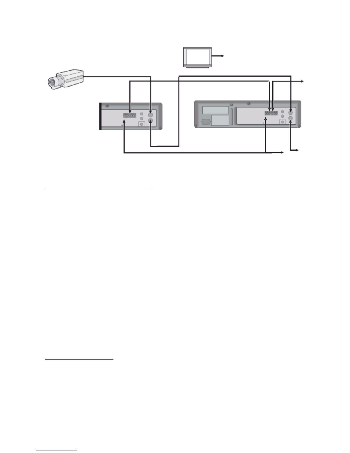
Connessioni
Collegare la telecamera e lo schermo TV come mostra lo schema seguente.
NOTA: accertarsi che tutti i dispositivi siano spenti prima di procedere con le connessioni.
o Per ulteriori dettagli, consultare i manuali di tutti gli altri dispositivi. Se le connessioni non sono
eseguite correttamente, può scoppiare un incendio oppure l’apparecchio si può danneggiare.
Telecamera
(venduta
separatamente)
Da una sorgente
audio esterna
Al morsetto di
uscita video
Al morsetto di
ingresso video
Schermo TV
(venduto
separatamente)
Page 12
4
Istallazione del cavo di alimentazione
Inserire la spina del cavo di alimentazione in una presa.
Videocassette
Utilizzare solo videocassette provviste del logo VHS .
Il presente VCR è stato progettato soprattutto per essere
utilizzato con videocassette. Si consiglia di utilizzare
videocassette VHS per prestazioni ottimali.
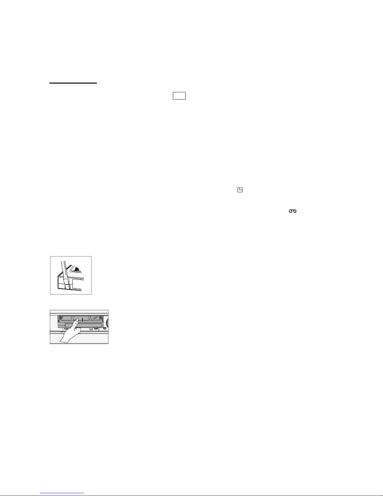
Maneggio delle videocassette
Riporre sempre le videocassette in posizione verticale nelle
custodie, al riparo da temperature elevate, campi magnetici,
raggi solari diretti, sporco e polvere e lontano da locali in cui
può formarsi la muffa.
Non manomettere il meccanismo della videocassetta.
Non toccare il nastro con le dita.
Proteggere le videocassette da urti e vibrazioni forti.
Protezione delle registrazioni
Una volta eseguita una registrazione su una videocassetta, per
conservare tale registrazione, utilizzare un cacciavite a punta
piatta per staccare la linguetta di protezione presente sulla
cassetta.
Per eseguire nuove registrazioni su una cassetta senza la
linguetta di protezione, coprire il buco con il nastro adesivo.
o Qualora l’utente cercasse di
eseguire registrazioni su una
cassetta sprovvista della linguetta di
protezione, il VCR espelle la
cassetta.
o Se l’utente preme il tasto TIMER
dopo aver inserito una cassetta
sprovvista della linguetta di
protezione, il VCR espelle la
cassetta, emette un suono di
segnalazione, se il segnalatore
acustico è impostato su “YES” nel
menu Buzzer (segnalatore acustico),
e l’indicatore registrazione con timer
( ) comincia a lampeggiare.
o Dopo che è stata inserita una
cassetta, sul display si illumina
l’indicatore cassetta .
o Il display visualizza il contatore di
reimpostazione. Lo schermo di
controllo visualizza “0H 00M 00S”
(0H 00M sul display).
Linguetta di protezione
Per evitare cancellazioni accidentali, rimuovere la linguetta una volta completata la
registrazione.
Per eseguire nuove registrazioni, coprire il buco con il nastro adesivo.
Inserimento di una videocassetta
Posizionare la cassetta con l’etichetta rivolta verso l’alto nell’apertura di inserimento.
Spingere delicatamente la parte centrale della cassetta finché non entra
automaticamente.
Espulsione di una videocassetta
In modalità Stop, premere il tasto Eject (espelli). Il VCR espelle
automaticamente la cassetta.
o Non inserire alcun oggetto
nell’apertura per l’inserimento
delle cassette per evitare lesioni e
danni al VCR.
o Se la mano dell’utente rimane
incastrata nell’apertura per
l’inserimento delle cassette,
scollegare il cavo di alimentazione
e rivolgersi al rivenditore.
o Non estrarre con la forza la mano
per evitare lesioni gravi.
Page 13

5
Tipi di on-screen display e successione degli OSD
• Se il VCR è in modalità stand-by registrazione con timer (sul display compare l’indicatore ),
l’OSD non è disponibile.
Innanzitutto premere il tasto Accensione/Timer, per annullare la modalità stand-by registrazione con
timer e procedere con la programmazione del VCR.
Una volta completata la programmazione, premere di nuovo il tasto Accensione/Timer per tornare in
modalità stand-by registrazione con timer.
• Quando l’utente visualizza un menu, non può avviare registrazioni.
• Premere il tasto Menu tre volte. Il procedimento di impostazione è completo e compare la
visualizzazione normale.
• Durante una registrazione o la riproduzione di un video, non è possibile accedere ai menu.
A
§ Premere il tasto MENU (prima volta)
§ Premere il tasto SHIFT ▼ (sposta) per spostare la freccia ► verso il basso sull’elemento desiderato.
§ Premere il tasto SHIFT ► (sposta) per selezionare l’elemento desiderato. L’utente visualizza
l’elemento desiderato.
§ Premere il tasto MENU per tornare alla visualizzazione normale dal menu iniziale.
B
§ Premere il tasto SHIFT ► (sposta) per selezionare l’elemento desiderato.
§ Premere il tasto SET – o + (imposta) per completare le impostazioni oppure premere il tasto SHIFT
► (sposta) per selezionare “YES” o “NO”.
§ Premere il tasto MENU per tornare al menu iniziale.
C
§ Premere il tasto SHIFT ► (sposta) (o SHIFT ▼) per selezionare l’elemento desiderato.
§ Premere il tasto SET – o + (imposta) per completare le impostazioni oppure premere il tasto SHIFT
► (sposta) per selezionare.
§ Premere il tasto MENU per tornare al menu precedente.
MENU
INIZIALE
SECONDO
GRUPPO DI
TERZO
GRUPPO DI
Page 14

6
Impostazione dell’orologio
Esempio: impostazione dell’orologio su 12 aprile 2004, ore 9:30
Impostazione dell’orologio
1. Accendere tutti gli apparecchi utilizzati.
2. Premere il tasto MENU per accedere al menu iniziale.
Il contrassegno a forma di freccia (►) si posiziona accanto a “VCR Mode Setup” (set-up della
modalità per il VCR).
3. Premere il tasto SHIFT ► (sposta) per accedere al menu VCR mode setup (set-up della modalità
per il VCR). Il contrassegno a forma di freccia (►) si posiziona accanto a “Clock Setup” (set-up
dell’orologio).
4. Premere il tasto SHIFT ► (sposta) per accedere al menu Clock Setup (set-up dell’orologio).
5. Premere il tasto SET – o + (imposta) per impostare le ore (es. 09) e premere il tasto SHIFT ►
(sposta).
6. Premere il tasto SET – o + (imposta) per impostare i minuti (es. 30) e premere il tasto SHIFT ►
(sposta).
7. I secondi sono già impostati su 00.
8. Premere il tasto SHIFT ► (sposta).
9. Premere il tasto SET – o + (imposta) per impostare il mese (es. 04) e premere il tasto SHIFT ►
(sposta).
10. Premere il tasto SET – o + (imposta) per impostare il giorno (es. 12) e premere il tasto SHIFT ►
(sposta).
11. Premere il tasto SET – o + (imposta) per impostare l’anno (es. 04 per il 2004).
• L’utente visualizza solo le ultime 2 cifre.
• Il giorno della settimana viene impostato automaticamente.
Page 15

7
12. Premere il tasto MENU tre volte per accedere alla visualizzazione normale.
• Ora il procedimento di impostazione è completo.
Accesso ai vari on-screen display (OSD)
Selezione dell’on-screen display
L’utente può scegliere di visualizzare l’ora, la data, il contatore di frame, il contatore degli eventi di allarme o
il contatore dei titoli.
1. Accendere tutti gli apparecchi.
2. Premere il tasto MENU.
L’utente accede al menu iniziale.
• Il contrassegno a forma di freccia (►) si posiziona accanto a “VCR MODE SETUP” (set-up modalità
per il VCR).
• Se nella parte superiore dello schermo appare una distorsione quando il VCR è collegato a un
Multiplexer, l’utente può commutare QV. Sync tra ON e OFF durante la riproduzione di un video
premendo SEL.
3. Premere il tasto SHIFT ► (sposta) per selezionare VCR MODE SETUP (set-up modalità per il
VCR). L’utente accede al menu VCR MODE SETUP (set-up modalità per il VCR).
4. Premere il tasto SHIFT ▼ (sposta) finché il contrassegno a forma di freccia ► si trova accanto a
Display setup (set-up display).
5. Premere il tasto SHIFT ► (sposta) per selezionare Display Setup (set-up display) per accedere al
menu DISPLAY SETUP (set-up display).
Page 16

8
6. Premere il tasto SET – o + (imposta) per impostare su YES le seguenti funzioni:
ORA Permette di visualizzare l’orario.
DATA Permette di visualizzare il mese, il giorno e l’anno.
CONTATORE FRAME Permette di visualizzare il numero di frame.
CONTATORE EVENTI DI ALLARME Permette di visualizzare il numero degli eventi di allarme.
CONTATORE Permette di visualizzare il contatore
TITOLO Permette di visualizzare il titolo
• È possibile utilizzare fino a 20 caratteri (lettere, numeri e spazi).
7. Premere il tasto SHIFT ► (sposta) per impostare la posizione della visualizzazione.
8. Premere il tasto SET – o + (imposta) per impostare la posizione dell’ora, della data, del contatore dei
frame, del contatori degli eventi di allarme su “L-Bottom (in basso a sinistra) o R-Bottom (in basso a
destra)”.
• Una volta impostata la posizione di uno dei 4 elementi, la posizione dei 4 elementi cambia nello
stesso modo.
9. Premere il tasto SET – o + (imposta) per impostare la posizione del contatore e del titolo su “CUpper (in alto in centro), R-Upper (in alto a destra) o L-Upper (in alto a sinistra)”.
Una volta impostata la posizione di uno dei 2 elementi, la posizione dei 2 elementi cambia nello
stesso modo.
10. Premere il tasto MENU tre volte per accedere alla visualizzazione normale.
Ora il procedimento di impostazione è completo.
o Gli elementi impostati su YES vengono registrati.
Gli elementi impostati su NO durante il passaggio 6 non vengono registrati.
Page 17
9
Registrazione normale
Registrazione normale
1. Accendere tutti gli apparecchi utilizzati.
2. Inserire una videocassetta provvista della linguetta di protezione.
3. Per impostare la velocità di registrazione, premere il tasto REC/PLAY SPEED ▼ (o ▲) (velocità di
registrazione/riproduzione).
• L’on-screen display e il display visualizzano la velocità di registrazione.
• Se l’utente non vuole registrare la velocità di registrazione, il contatore, il titolo, l’ora, la data, ecc.,
occorre premere il tasto DISPLAY e, quindi, avviare la registrazione.
4. Premere il tasto REC (registra).
• Il display visualizza l’indicatore REC e la registrazione inizia.
5. Per interrompere la registrazione, premere il tasto STOP.
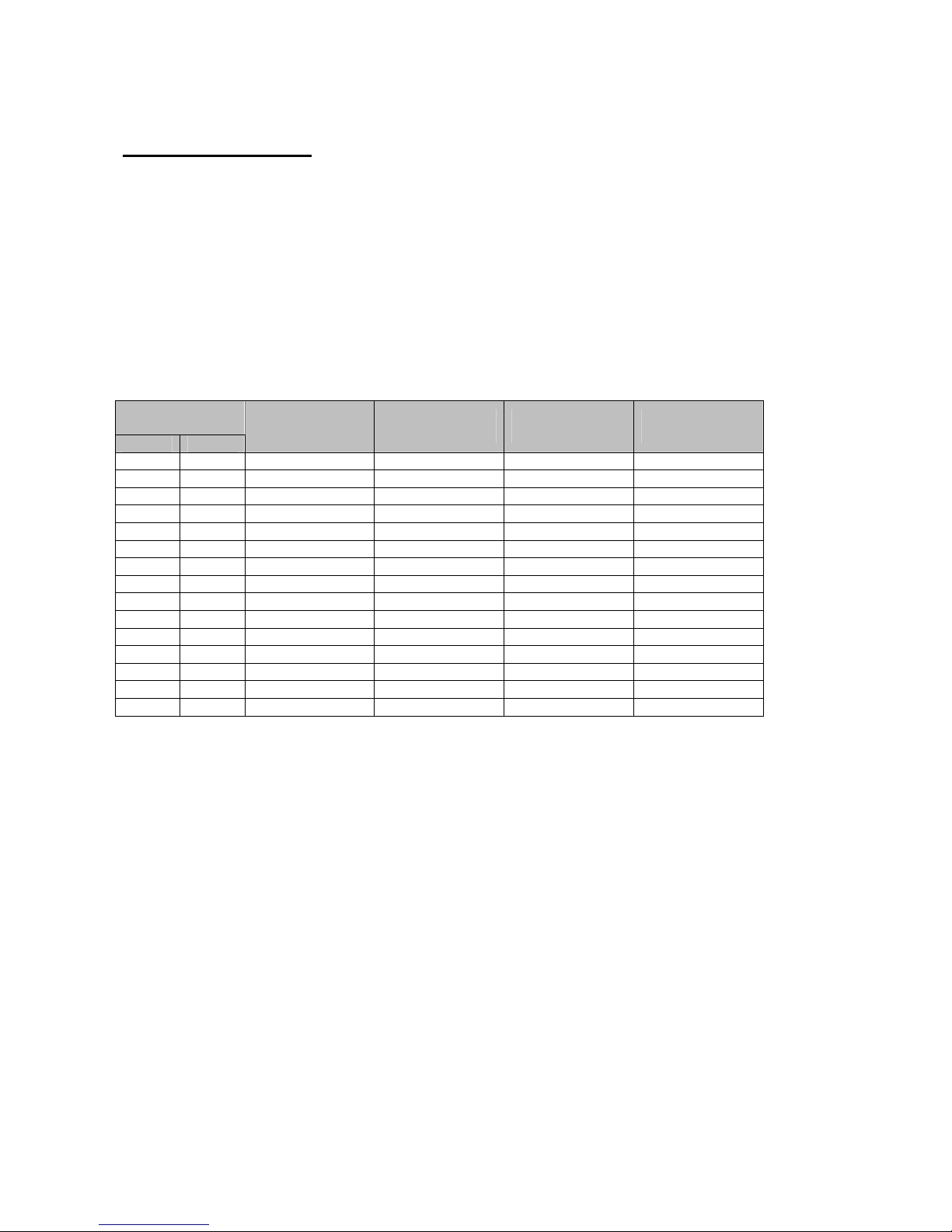
Velocità di registrazione
Velocità di
registrazione
E-180 E-240
Intervalli di
registrazione
Registrazione
campo/secondi
Registrazione
audio
Avanzamento del
nastro
3H 4H 1/60 sec. 50 Sì Continuo
6H 8H 1/60 sec. 50 Sì Continuo
18H 24H 3/60 sec. 20 Sì Continuo
30H 40H 15/60 sec. 10 Sì Continuo
48H 68H 24/60 sec. 2,9 NO Intermittente
72H 100H 36/60 sec. 2 NO Intermittente
96H 132H 48/60 sec. 1,5 NO Intermittente
120H 164H 1 sec. 1,2 NO Intermittente
168H 228H 1,4 sec. 0,87 NO Intermittente
240H 324H 2 sec. 0,61 NO Intermittente
360H 484H 3 sec. 0,41 NO Intermittente
480H 644H 4 sec. 0,31 NO Intermittente
720H 964H 6 sec. 0,20 NO Intermittente
960H 1284H 8 sec. 0,15 NO Intermittente
1280H 1708H 10,7 sec. 0,1 NO Intermittente
v (SP): la registrazione è affidata testine SP.
v (EP): la registrazione è affidata a testine EP.
v Modalità 12H, 24H (solo Pb).
o Se Repeat Rec Set (impostazione registrazione continua) all’interno del menu REC MODE SET
(impostazione modalità di registrazione) è impostata su NO, la registrazione continua fino al termine
del nastro, poi si arresta e il VCR espelle la cassetta.
o Una registrazione eseguita con il presente VCR non può essere riprodotta su un VCR con intervalli
di tempo diversi.
o Se l’utente preme il tasto REC (registra) e la cassetta inserita è sprovvista della linguetta di
protezione, il VCR espelle la cassetta.
o Durante una registrazione, il tasto Menu non è disponibile (non è possibile accedere al menu).
Pausa durante una registrazione
È possibile interrompere momentaneamente una registrazione.
1. Premere il tasto PAUSE/STILL (pausa/fermo immagine) mentre la registrazione è in corso.
Il display visualizza gli indicatori REC e II.
2. Per procedere con la registrazione, premere il tasto REC oppure premere di nuovo il tasto PAUSE/STILL
(pausa/fermo immagine).
o La riproduzione della parte di nastro sottoposta a controllo della registrazione può essere
caratterizzata da interferenze.
o Se l’utente modifica la velocità di registrazione durante una registrazione, può causare una perdita
del segnale o interferenze.
Page 18

10
o Durante una pausa, l’immagine che appare sullo schermo non viene registrata.
o Se l’utente interrompe la registrazione per 5 o più minuti, il VCR entra in modalità STOP per evitare
che il nastro si danneggi.
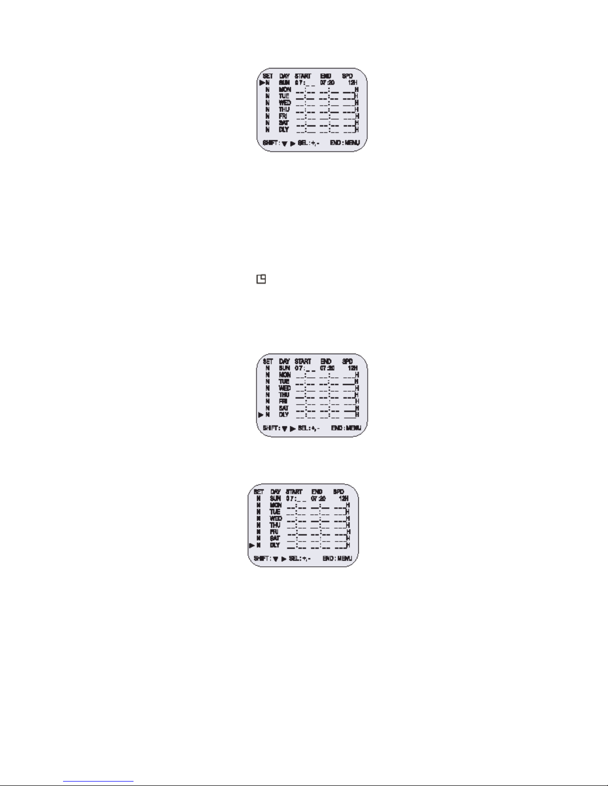
Programmazione della registrazione con timer
Sono previsti due metodi per programmare una registrazione con timer: registrazione giornaliera o
registrazione in determinati giorni per diverse settimane (registrazione settimanale).
Esempio 1: per registrare ogni giovedì dalle 10:00 alle 18:00, in modalità 24 ore (velocità di registrazione).
1. Accertarsi che la data e l’ora impostate siano corrette.
2. Inserire una cassetta provvista della linguetta di protezione.
3. Premere in successione il tasto MENU, il tasto SHIFT ▼ (sposta), il tasto SHIFT ► (sposta) e il tasto
SHIFT ► (sposta) per accedere al menu TIMER PROGRAM SETUP (set-up della programmazione del
timer).
• Il cursore bianco di blocco è posizionato su SUN (domenica).
4. Premere il tasto SHIFT ▼ (sposta) finché il cursore si posiziona su THU (giovedì).
5. Premere il tasto SHIFT ► (sposta).
• Il cursore si sposta sulla posizione dell’ora di inizio della registrazione.
6. Premere il tasto SET – o + (imposta) per impostare l’ora da cui iniziare la registrazione (es. 10) e
premere il tasto SHIFT ► (sposta).
• Il cursore si sposta sulla posizione dei minuti di inizio della registrazione.
7. Premere il tasto SET – o + (imposta) per impostare i minuti da cui iniziare la registrazione (es. 00) e
premere il tasto SHIFT ► (sposta).
• Il cursore si sposta sulla posizione dell’ora di fine della registrazione.
8. Premere il tasto SET – o + (imposta) per impostare l’ora in cui terminare la registrazione (es. 06) e
premere il tasto SHIFT ► (sposta).
• Il cursore si sposta sulla posizione dei minuti di fine della registrazione.
9. Premere il tasto SET – o + (imposta) per impostare i minuti in cui terminare la registrazione (es. 00) e
premere il tasto SHIFT ► (sposta).
10. Premere il tasto SET – o + (imposta) per selezionare la velocità di registrazione (es. 24) e premere il
tasto SHIFT ► (sposta).
• Il cursore si sposta sulla posizione Y/N (sì/no).
o Se l’orario impostato per la fine della registrazione precede o coincide con l’orario di inizio della
registrazione, il VCR imposta la data del giorno successivo per l’orario di fine della registrazione.
11. Premere il tasto SET – o + (imposta) per selezionare Y (sì).
Y La registrazione è confermata
N La registrazione non è confermata
Esempio 1 registrazione con timer programmata.
Page 19
11
• Ripetere i passaggi 4-13 per programmare registrazioni con timer per altri giorni della settimana.
• Per impostare altre registrazioni con timer per lo stesso giorno della settimana, premere il tasto
SHIFT ▼ (sposta) finché in cursore si posiziona sul giorno della settimana in cui deve essere
impostata la seconda registrazione e premere il tasto SET – o + (imposta) per impostare il
giorno della settimana desiderato. Premendo il tasto SET – o +, il giorno cambia secondo la
successione indicata qui di seguito.
SET -: <-------- direzione, SET +: --------> direzione
→SUN↔MON↔TUE↔WED↔THU↔FRI↔SAT↔DLY←
12. Premere il tasto MENU tre volte per accedere alla visualizzazione normale.
13. Premere il tasto Power/timer (accensione/timer).
L’indicatore di registrazione con timer “ ” si illumina sul display.
Il VCR è ora in modalità stand-by registrazione con timer.
Esempio 2: per registrare ogni giorno dalle 10:00 alle 18:00, in modalità 24 ore (velocità di registrazione).
1. Ripetere i passaggi 1-3.
2. Premere il tasto SHIFT ▼ (sposta) finché il cursore si posiziona su DLY (registrazione giornaliera).
L’utente accede al seguente menu.
3. Ripetere i passaggi 5-13.
Esempio 2 registrazione con timer programmata.
o Per modificare, annullare una registrazione con timer, premere il tasto Power/timer
(accensione/timer): la modalità di registrazione con timer è disattivata.
Modifica di una registrazione con timer programmata
1. Premere in successione il tasto MENU, il tasto SHIFT ▼ (sposta), il tasto SHIFT ► (sposta) e il
tasto SHIFT ► (sposta) per accedere al menu TIMER PROGRAM SETUP (set-up della
programmazione del timer).
2. Premere il tasto SHIFT ► o SHIFT ▼ (sposta) finché il cursore si posiziona sull’impostazione da
correggere.
3. Per correggere l’impostazione, premere il tasto SET – o + (imposta).
• Premere il tasto MENU tre volte per accedere alla visualizzazione normale.
4. Premere il tasto Power/timer (accensione/timer).
Page 20

12
Annullamento dei una registrazione con timer programmata
1. Ripetere il passaggio 1 descritto in precedenza.
2. Premere il tasto SHIFT ► o SHIFT ▼ (sposta) finché il cursore si posiziona su Y (sì) in
corrispondenza della registrazione con timer da annullare.
3. Premere il tasto SET – o + per selezionare N (no).
4. Premere il tasto MENU tre volte per accedere alla visualizzazione normale.
5. Premere il tasto Power/timer (accensione/timer).
• Il tasto Clear (cancella) permette di cancellare la registrazione con timer programmata presente sulla
riga in cui si trova il cursore.
Note…….
• Durante una registrazione con timer, tutti i tasti presenti sul VCR sono disattivati, tranne il tasto
STOP che consente di arrestare la registrazione. Durante una registrazione con timer, premere il
tasto Power/timer (accensione/timer) se i tasti non sono disponibili.
• Qualora mancasse la corrente di alimentazione, la registrazione si interrompe.
Quando la corrente di alimentazione viene ripristinata, la registrazione riprende se l’orario di fine non
è stato raggiunto. Sul display lampeggia PWR.
La batteria interna del VCR è completamente carica dopo che il VCR è stato collegato per 48 ore a
una presa di corrente AC e conserva tutte le impostazioni del VCR memorizzate per 30 giorni al
massimo.
• Impostare le registrazioni con timer cosicché gli orari delle registrazioni non coincidano.
In caso contrario, la registrazione che inizia per prima avrà la priorità.
• Se il VCR espelle la cassetta durante una registrazione con timer, il segnalatore acustico emette un
suono di segnalazione per 5 volte (se la funzione segnalatore acustico è stata attivata).
Registrazione degli eventi di allarme
Impostazione della registrazione degli eventi di allarme
Quando in corrispondenza del morsetto di ingresso allarme viene rilevato un input (attivazione), ha inizio la
registrazione degli eventi di allarme (il display visualizza il simbolo ).
1. Contrassegnare tutte le connessioni necessarie.
2. Premere in successione il tasto MENU, SHIFT ▼ e SHIFT ► (sposta) per accedere al menu REC
MODE SETUP (set-up della modalità di registrazione).
3. Premere il tasto SHIFT ▼ (sposta) finché il contrassegno a forma di freccia (►) indica Alarm Rec
Setup (set-up registrazione eventi di allarme).
4. Premere il tasto SHIFT ► (sposta) per accedere al menu ALARM REC SETUP (set-up registrazione
eventi di allarme).
Programma 1
Programma 2
Programma 3
Queste parti non
saranno registrate.
Page 21
13
5. Premere il tasto SHIFT ► (sposta) per selezionare YES o NO.
YES La registrazione degli eventi di allarme ha inizio quando è presente un input di attivazione
dell’allarme.
NO La registrazione degli eventi di allarme non ha inizio.
6. Premere il tasto SHIFT ▼ (sposta) per impostare la velocità dell’evento di allarme.
7. Premere il tasto SHIFT ► (sposta) per selezionare la velocità di registrazione desiderata.
06H Registrazione in modalità 6 ore
30H Registrazione in modalità 30 ore
8. Premere il tasto SHIFT ▼ (sposta) per impostare la durata dell’evento di allarme.
9. Premere il tasto SHIFT ► (sposta) per selezionare la durata della registrazione.
• Auto: la registrazione prosegue finché è attivo il segnale di allarme (la registrazione dura almeno 2
minuti).
• 03/05/10/15/20/25/30/T-end MIN: la registrazione ha la durata stabilita (MIN: minuti).
• T-END: la registrazione prosegue finché non finisce il nastro quando viene rilevato un input di
attivazione allarme (nota: se è attiva la modalità di durata T-END, non è possibile eseguire
registrazioni continue).
o Durante la registrazione di un evento di allarme, tutti i tasti sono disattivati, eccetto il tasto STOP.
Premendo il tasto STOP, l’utente interrompe la registrazione dell’evento di allarme.
o Se viene rilevato un evento di allarme durante la registrazione di un evento di allarme, la durata della
registrazione per il secondo evento di allarme sarà calcolata da quel punto.
o Qualora mancasse la corrente di alimentazione durante la registrazione di un evento di allarme, la
registrazione prosegue una volta ripristinata la corrente di alimentazione (nota: il contatore degli
allarmi conteggia un nuovo allarme).
Visualizzazione del contatore delle registrazioni degli eventi di allarme
Durante la registrazione di un evento di allarme il simbolo __ lampeggia sul display.
Il numero massimo di eventi di allarme visualizzati è 35. Successivamente, se viene rilevato un evento di
allarme, Il contatore riparte da 00.
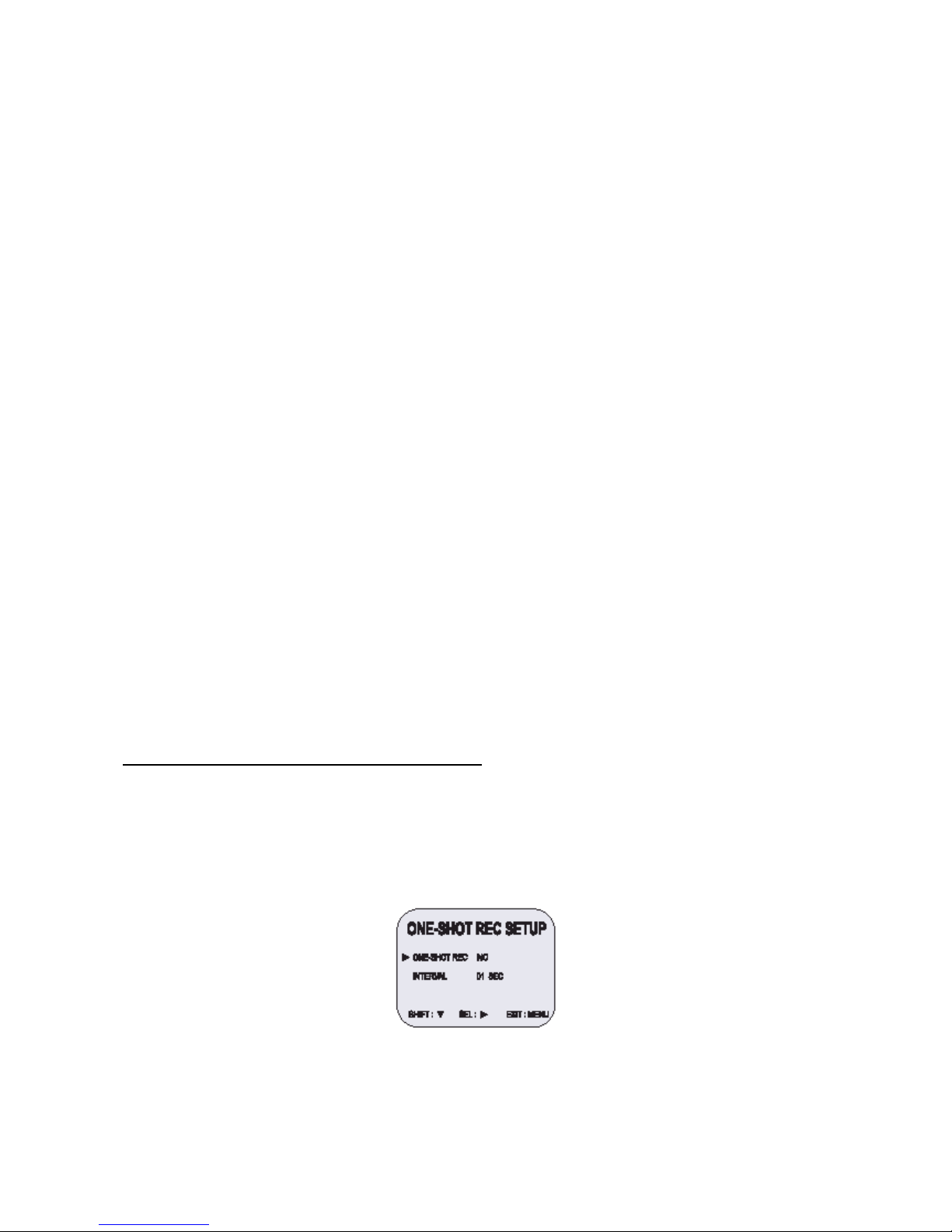
Registrazione one-shot (singola immagine)
Impostazione della registrazione one-shot (singola immagine)
1. Premere in successione il tasto MENU, il tasto SHIFT ► (sposta) e il tasto SHIFT ► (sposta) per
accedere al menu REC MODE SETUP (set-up della modalità di registrazione).
2. Premere il tasto SHIFT ▼ (sposta) finché il tasto a forma di freccia (►) indica ONE-SHOT REC
SETUP (set-up della registrazione one-shot).
3. Premere il tasto SHIFT ►(sposta) per accedere al menu ONE-SHOT REC SETUP (set-up della
registrazione one-shot).
4. Premere il tasto SHIFT (►) (sposta) per selezionare YES o NO.
5. Premere il tasto SHIFT (▼) (sposta) per impostare l’intervallo one-shot.
6. Premere il tasto SHIFT ► (sposta) per selezionare l’intervallo di registrazione desiderato.
• Modalità di intervallo: 01/02/03/05/10/20/30/60/ off (secondi)
Page 22

14
OFF: la modalità di intervallo OFF indica che il VCR è impostato in modo da ricevere i
segnali esterni attraverso il morsetto one-shot.
7. Premere il tasto REC.
• Il display visualizza l’indicatore REC 000H e la registrazione inizia.
• Il monitor visualizza l’indicatore 1SHOT.
8. Per interrompere la registrazione, premere il tasto STOP.
Registrazione con collegamento (serie)
Qualora l’utente utilizzasse 2 o più VCR, la funzione di registrazione con collegamento consente di
commutare la registrazione da un apparecchio all’altro (solo se i VCR sono dello stesso modello).
Set-up della registrazione con collegamento
1. Collegare 2 o più VCR come descritto qui di seguito.
2. Impostare i seguenti elementi come indicato.
Elemento VCR n.°1 VCR n.°2 e successivi
Cassetta Inserita Inserita
Modalità di funzionamento Stop Stop
Impostazione registrazione
continua
NO NO
Impostazione registrazione con
collegamento
YES YES
Registrazione con timer OFF (non impostata) OFF (non impostata)
Commutatore blocco di sicurezza
(commutatore SET LOCK –
imposta blocco -)
OFF ON
o Il contatore degli eventi di allarme può essere reimpostato premendo il tasto CLEAR (cancella)
accedendo ad Alarm Time (durata allarme) all’interno del menu iniziale.
o Durante la registrazione con collegamento, non sono disponibili la registrazione continua automatica
e la registrazione con timer.
o Se all’interno del menu REC MOD SET (impostazione della modalità di registrazione) Link Rec Set
(impostazione della registrazione con collegamento) è impostato su NO, la registrazione non
collegamento non è disponibile.
3. Premere il tasto REC presente sul VCR n.°1.
• La registrazione con modalità di registrazione in serie inizia.
4. Impostare il blocco di sicurezza per il VCR n.°1.
• Quando lo spazio disponibile sul nastro inserito nel VCR n°1 termina, l’uscita in
corrispondenza del morsetto di uscita di collegamento (uscita di serie) commuta il segnale.
In questo modo il VCR n.°2 inizia a registrare. Il nastro presente nel VCR n.°1 si arresta e il
VCR espelle la cassetta.
Page 23
15
Registrazione continua automatica
Registrazione continua automatica
È possibile registrare molte volte sullo stesso nastro.
1. Premere in successione il tasto MENU, il tasto SHIFT ▼ e il tasto SHIFT ► (sposta) per accedere al
menu REC MODE SETUP (set-up della modalità di registrazione).
2. Premere il tasto SHIFT ► (sposta) finché il contrassegno a forma di freccia (►) indica Repeat Rec
Set (impostazione registrazione continua).
3. Premere il tasto SHIFT ► (sposta) per impostare la modalità di registrazione continua automatica
desiderata.
NO La registrazione continua automatica non è attiva.
YES La registrazione continua automatica è attiva.
Il pannello del display visualizza R.REC.
4. Premere il tasto Menu due volte per accedere alla visualizzazione normale.
• Ora il procedimento di impostazione è completo.
5. Premere il tasto REC.
• La registrazione comincia. A fine nastro, il VCR riavvolge la cassetta fino all’inizio senza
modificare la memoria del contatore e riavvia la registrazione (nota: se all’interno del menu
ALARM REC SETUP – set-up della registrazione degli eventi di allarme – l’utente ha
impostato la modalità di durata su T-END, la registrazione continua non è disponibile).
o Se durante la registrazione continua automatica viene rilevato un’attivazione di allarme, il display
visualizza il simbolo __ e comincia la registrazione dell’evento di allarme. La durata della registrazione
continua automatica è terminata.
Riproduzione normale
Riproduzione normale
1. Accendere lo schermo TV.
Telecamera
Schermo TV
Al jack di uscita
video (VCR)
VCR n.°1
VCR n.°2
Al morsetto
di massa
All’
uscita
di serie
Al jack di
ingresso video
Al morsetto
di massa
Al morsetto di
massa (VCR n. 3)
Al jack di
uscita video
Al jack di
uscita video
All’
uscita
di serie
Al jack di
ingresso
video
All’
ingresso
di serie
Page 24

16
2. Inserire la videocassetta.
3. Premere il tasto REC/PLAY SPEED ▼ o ▲ (velocità registrazione/riproduzione) per selezionare la
velocità di riproduzione.
• Il display visualizza la velocità di riproduzione selezionata.
• Un nastro registrato con testine SP può essere riprodotto in 2 ore/30 ore…….
4. Premere il tasto PLAY (riproduci).
• Inizia la riproduzione.
• Se occorre, regolare il tracking per eliminare le interferenze dall’immagine.
5. Per arrestare la riproduzione, premere il tasto STOP.
• Per avvolgere o riavvolgere il nastro, premere il tasto FF/CUE o il tasto REW/REVIEW.
Controllo Tracking
Se durante la riproduzione l’utente rileva interferenze nell’immagine,
1. Premere e tenere premuto il tasto TRACKING+ durante la riproduzione per ridurre le
interferenze.
2. Qualora non fosse possibile ridurre le interferenze, premere il tasto TRACKING-.
3. In modalità riproduzione, premere il tasto PLAY (riproduci).
Riproduzione audio
L’audio può essere riprodotto solo nelle modalità 2, 6, 18 e 30 ore. È necessario che la velocità di
riproduzione coincida con la velocità di registrazione per ottenere una riproduzione normale dell’audio.
Per riprodurre l’audio di una cassetta registrata in modalità 2, 6, 18 e 30 ore, premere il tasto AUDIO ON
(audio attivo) dopo aver premuto il tasto PLAY (riproduci).
Il display visualizza A alla sinistra della velocità di riproduzione. Premere di nuovo il tasto AUDIO ON (audio
attivo) per rimuovere A.
o Per riprodurre le immagini come se fossero accelerate o al rallentatore, utilizzare una velocità di
riproduzione maggiore o minore rispetto alla velocità di registrazione.
Riproduzione speciale
Ricerca delle immagini
1. Durante la riproduzione normale, premere il tasto FF/CUE oppure il tasto REW/REVIEW.
• Mentre il VCR avvolge o riavvolge il nastro ad alta velocità, l’utente può visualizzare
l’immagine.
2. Per tornare alla riproduzione normale, premere il tasto PLAY (riproduci).
Fermo immagine
1. Durante la riproduzione normale, premere il tasto PAUSE/STILL (pausa/fermo immagine).
• L’immagine è ferma.
2. Per tornare alla riproduzione normale, premere il tasto PLAY (riproduci).
• Ogni volta che l’utente preme il tasto PAUSE/STILL, l’immagine si muove di un fotogramma.
Page 25

17
Controllo blocco verticale
In modalità fermo immagine,
1. Premere il tasto TRACKING+ per ridurre il movimento verso l’alto dell’immagine.
2. Se non è possibile correggere l’immagine, premere il tasto TRACKING-.
Rallentatore
1. In modalità fermo immagine, ogni volta che l’utente preme il tasto FF(F.ADV), la velocità del
rallentatore cambia secondo lo schema qui riportato.
1/15 volte --------------> 1/20 volte -------------> 1/30 volte (avvolgimento)
2. In modalità fermo immagine ogni volta che l’utente preme il tasto REW, la velocità del rallentatore
cambia secondo lo schema qui riportato.
1/15 volte --------------> 1/10 volte --------------> 1/5 volte (riavvolgimento)
3. Per tornare alla riproduzione normale, premere il tasto PLAY (riproduci).
Controllo della registrazione
Durante la registrazione, premere il tasto PLAY/REC CHECK (controllo riproduzione/registrazione).
Il nastro viene riavvolto per circa 5 secondi in modalità rallentatore.
Il VCR torna alla modalità di registrazione impostata in precedenza.
Ricerca degli eventi di allarme
1. Premere il tasto Menu per accedere al menu iniziale.
2. Premere il tasto SHIFT ▼ (sposta) per selezionare Search Select (selezione della ricerca) e
premere il tasto SHIFT ► (sposta) per accedere al menu SEARCH SELECT (selezione della
ricerca).
o Durante la ricerca di un’immagine, l’utente rileva interferenze nell’immagine visualizzata (barre
orizzontali).
o L’audio non è attivo.
o Se la modalità fermo immagine rimane attiva per 5 o più minuti, il VCR attiva automaticamente la
modalità Stop per evitare che il nastro si danneggi.
o Se l’immagine visualizzata è instabile (si sposta in verticale), regolare il controllo Tracking per
correggerla.
o Durante il controllo, la registrazione si interrompe momentaneamente.
3. In modalità Alarm Search (ricerca degli eventi di allarme), l’utente scegliere di impostare il
contrassegno a forma di freccia (►) su FF (avanti veloce) o REW (riavvolgi) secondo la direzione di
ricerca desiderata.
4. Premere il tasto SET- o + (imposta) per inserire il numero dei contrassegni di allarme da cercare.
Premere il tasto SHIFT ► (sposta) per cercare in avanti o all’indietro.
• Il display torna alla visualizzazione normale.
• Il VCR individua la registrazione dell’evento di allarme desiderato e ne avvia la riproduzione.
Page 26

18
Analisi degli eventi di allarme
1. Ripetere i passaggi 1-3.
2. Premere il tasto SHIFT ► (sposta) per cercare in avanti o all’indietro senza inserire il numero
specifico dell’evento di allarme.
• Il display torna alla visualizzazione normale.
• Il VCR avvolge (o riavvolge) il nastro ad alta velocità e riproduce i primi 5 secondi di ogni
evento di allarme registrato.
• Per disattivare la modalità analisi degli eventi di allarme, premere il tasto STOP.
3. Durante la riproduzione di una determinata registrazione scelta dall’utente, premere il tasto PLAY
(riproduci) per avviare la riproduzione e l’analisi degli eventi di allarme si disattiva.
Ricerca degli indici
1. Ripetere i passaggi 1-2.
2. In modalità Index Search (ricerca degli indici) l’utente può scegliere di posizionare il contrassegno a
forma di freccia (►) su FF (avanti veloce) o REW (riavvolgi) secondo la direzione di ricerca
desiderata.
3. Premere il tasto SHIFT ► (sposta) perché la ricerca proceda in avanti o all’indietro.
• Il display torna alla visualizzazione normale.
• Il VCR avvolge (o riavvolge) il nastro ad alta velocità e riproduce i primi 5 secondi di ogni
registrazione normale.
• Per disattivare la modalità Index Search (ricerca degli indici), premere il tasto STOP.
4. Durante la riproduzione della registrazione desiderata, premere il tasto PLAY (riproduci).
• La riproduzione comincia e la modalità Index Search (ricerca degli indici) è disattivata.
o Quando è attiva la modalità Index Search (ricerca degli indici), utilizzare il tasto SHIFT ► per effettuare
la ricerca in avanti o all’indietro (Indice avanti veloce/riavvolgi).
o Occorre tenere presente che quando l’utente preme il tasto CUE 7 per far avanzare velocemente il nastro,
sullo schermo appaiono le bande di interferenza.
o Non si tratta di un difetto, ma di un fenomeno momentaneo che sparisce presto.
Altre funzioni
Contatore del nastro (ricerca zero)
Utilizzare il contatore per trovare facilmente la registrazione desiderata.
1. Premere il tasto CLEAR (cancella) all’inizio della registrazione desiderata.
• Il contatore viene reimpostato su 0H 00M 00S (sullo schermo).
• Il contatore viene reimpostato su 0H 00M (sul display).
2. Una volta completata la riproduzione o la registrazione, premere il tasto Menu per accedere al menu
iniziale.
3. Premere il tasto SHIFT ▼ (sposta) per posizionare il contrassegno a forma di freccia (►) su Search
Select (selezione della ricerca).
Riproduzione
Numero dell’evento di allarme
Punto di ingresso dell’attivazione dell’allarme
Avvolgimento Avanzamento rapido
Posizione reale
Page 27

19
4. Premere il tasto SHIFT ► (sposta) per accedere al menu SEARCH SELECT (selezione della
ricerca). Il menu SEARCH SELECT appare.
5. Premere il tasto SHIFT ▼ (sposta) per posizionare il contrassegno a forma di freccia (►) su Zero
Search (ricerca zero).
6. Premere il tasto SHIFT ► (sposta) per cercare il contatore 0H 00M 00S (il display visualizza 0H
00M).
• Il display torna alla visualizzazione normale.
• Il VCR riavvolge o avvolge il nastro fino alla registrazione 0H 00M 00S del contatore (il
display visualizza 0H 00M).
o Quando l’utente inserisce una cassetta, il contatore ripristina sempre Zero come valore.
o Il contatore non visualizza alcuna indicazione per le parti vuote del nastro.
o Solo in modalità velocità di registrazione 2 ore, il contatore del nastro indica le ore, i minuti e i secondi
effettivi.
o Tra la posizione indicata dal contatore del nastro e la posizione reale del nastro può esserci una leggera
discrepanza.
o Quando viene riavvolto il nastro oltre la posizione 0H 00M 00S (il display visualizza 0H 00M), il display
visualizza un meno (-).
Impostazione del blocco di sicurezza (Impostazione del blocco).
La funzione del blocco di sicurezza è stata progettata per evitare che la registrazione venga interrotta
accidentalmente se viene premuto involontariamente il tasto STOP.
1. Impostare il commutatore del blocco di sicurezza su ON.
• Il display visualizza il simbolo .
2. Per disattivare il blocco di sicurezza, impostare il commutatore del blocco di sicurezza su OFF.
• Il display non visualizza più il simbolo .
Impostazione dell’uscita del morsetto dell’uscita di attivazione
Il morsetto dell’uscita dell’attivazione permette di sincronizzare gli impulsi diretti ai multiplexer.
1. Premere il tasto MENU per accedere al menu iniziale.
2. Premere il tasto SHIFT ▼ (sposta) per posizionare il contrassegno a forma di freccia (►) su REC
MODE SETUP (set-up della modalità di registrazione).
3. Premere il tasto SHIFT ► (sposta) per accedere al menu TRIGGER OUT SETUP (set-up dell’uscita
di attivazione).
4. Premere il tasto SHIFT ► (sposta) per impostare FRAME.
Ogni volta che l’utente preme il tasto SHIFT ► (sposta), l’impostazione varia secondo il seguente
schema.
5. Premere il tasto SHIFT ► (sposta) per impostare FRAME.
• FRAME … il primo impulso è emesso dopo il numero di frame impostato.
Page 28

20
6. Premere il tasto MENU per accedere alla visualizzazione normale.
• Ora il procedimento di impostazione è completo.
o Quando la funzione del blocco di sicurezza è attiva, tutti i comandi sono disattivati.
o Evitare di attivare il blocco di sicurezza durante la visualizzazione di un menu.
Impostazione del segnalatore acustico
1. Premere il tasto MENU per accedere al menu iniziale.
2. Premere il tasto SHIFT ► (sposta) per selezionare VCR MODE SETUP (set-up della modalità per il
VCR).
L’utente accede al menu VCR MODE SETUP (set-up della modalità per il VCR).
3. Premere il tasto SHIFT ▼ (sposta) per posizionare il contrassegno a forma di freccia (►) su
BUZZER SET (impostazione del segnalatore acustico).
4. Premere il tasto SHIFT ► (sposta) per impostare su YES le funzioni descritte qui di seguito.
Il segnalatore acustico emette un suono ogni volta che l’utente preme un tasto.
Impostazione della modalità video
1. Premere il tasto MENU per accedere al menu iniziale.
2. Premere il tasto SHIFT ► (sposta) per selezionare VCR MODE SETUP (set-up della modalità per il
VCR).
L’utente accede al menu VCR MODE SETUP (set-up della modalità per il VCR).
3. Premere il tasto SHIFT ▼ (sposta) per posizionare il contrassegno a forma di freccia (►) su VIDEO
MODE (modalità video).
4. Premere il tasto SHIFT ► (sposta) per impostare COLOR (colori) o B/W (bianco e nero) per le
funzioni descritte qui di seguito.
v Nota: impostare la modalità video su B/W (bianco e nero) durante la riproduzione se la
registrazione è stata eseguita con una telecamera in bianco e nero.
v Quando la modalità video è impostata su B/W (bianco e nero), le immagini riprodotte o
registrate sono in bianco e nero.
o Nei seguenti casi il segnalatore acustico emette un suono circa 5 volte.
o Se l’utente preme il tasto REC dopo aver inserito una cassetta sprovvista della linguetta di protezione.
o Se l’utente inserisce una cassetta sprovvista della linguetta di protezione dopo aver impostato il timer.
o Se l’utente attiva una registrazione con collegamento e la cassetta inserita è sprovvista della linguetta di
protezione.
o Se l’utente preme il tasto TIMER e non inserisce alcuna cassetta nel VCR.
Page 29

21
o Se è impostato su NO, il segnalatore acustico non funziona.
Controllo del numero di eventi di allarme registrati
1. Premere il tasto MENU per accedere al menu iniziale.
2. Premere il tasto SHIFT ▼ (sposta) per posizionare il contrassegno a forma di freccia (►) su ALARM
RECALL (richiama gli eventi di allarme).
3. Premere il tasto SHIFT ► (sposta) per accedere al menu ALARM RECALL (richiama gli eventi di
allarme).
L’utente visualizza il numero degli eventi di allarme e i 35 eventi di allarme più recenti.
4. Premere due volte il tasto MENU per accedere alla visualizzazione normale.
Controllo della memoria degli episodi in cui è mancata la corrente
1. Premere il tasto MENU per accedere al menu iniziale.
2. Premere il tasto SHIFT ▼ (sposta) per posizionare il contrassegno a forma di freccia (►) su
POWER FAIL RECALL (richiama gli episodi in cui è mancata la corrente di alimentazione).
3. Premere il tasto SHIFT ► (sposta) per accedere al menu POWER FAIL RECALL (richiama gli
episodi in cui è mancata la corrente di alimentazione).
L’utente visualizza il numero di episodi in cui è mancata la corrente di alimentazione e i 35 episodi
più recenti.
4. Premere due volte il tasto MENU per accedere alla visualizzazione normale.
o I dati relativi agli eventi di allarme precedenti e non compresi tra i 35 visualizzati vengono cancellati.
o POWER FAIL……………. L’utente accede ai 35 episodi più recenti in cui è mancata la corrente e ai dati
relativi alla data e all’orario in cui è mancata ed è stata ripristinata la corrente di alimentazione.
Controllo della durata di utilizzo
1. Premere il tasto MENU per accedere al menu iniziale.
USED HEAD HOURS: la durata di utilizzo delle testine video.
Page 30

22
2. Premere il tasto MENU per accedere alla visualizzazione normale.
Impostazione dei morsetti di ingresso e di uscita
1. Premere il tasto MENU per accedere al menu iniziale.
2. Premere il tasto SHIFT ► (sposta) per accedere al menu VCR MODE SETUP (set-up della modalità
per il VCR).
3. Premere il tasto SHIFT ▼ (sposta) per posizionare il contrassegno a forma di freccia (►) su
In/Output Setup (set-up ingressi/uscite).
4. Premere il tasto SHIFT ► (sposta) per accedere al menu IN/OUTPUT SETUP (set-up
ingressi/uscite).
5. Premere il tasto SHIFT ▼ (sposta) per spostare il contrassegno a forma di freccia (►) sull’elemento
desiderato.
6. Premere il tasto SHIFT ► (sposta) per impostare N/O oppure N/C, High oppure Low.
• N/O: aperto normale
• N/C: chiuso normale
7. Premere tre volte il tasto MENU per accedere alla visualizzazione normale.
Sincronizzazione quasi verticale
1. Premere il tasto MENU per accedere al menu iniziale.
2. Premere il tasto SHIFT ▼ (sposta) per posizionare il contrassegno a forma di freccia (►) su Q.V
SYNK SETUP (set-up sincronizzazione quasi verticale).
3. Premere il tasto di selezione ► per selezionare il sistema corretto (ON -> OFF).
Disattivare questa funzione se l’utente utilizza un multiplexer (attivare questa funzione quando
l’utente non utilizza un multiplexer).
Attenzione
Quando il VCR avvolge o riavvolge il nastro, l’utente può visualizzare interferenze nella parte superiore e
inferiore dell’immagine.
o Anche premendo il tasto RESET, non è possibile reimpostare i dati relativi all’orario della registrazione.
Premendo il tasto RESET, è possibile reimpostare tutti i dati tranne l’orario della registrazione.
Page 31
23
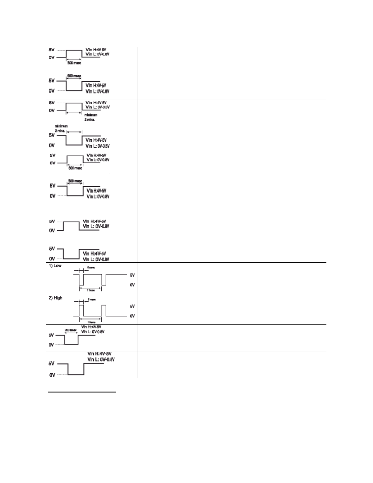
Morsetto di ingresso dell’allarme
1. N/C (il circuito del commutatore è chiuso normale). Se l’ingresso
diventa DC 5V per 500 o più millisecondi, il VCR avvia la
registrazione di un evento di allarme.
2. N/O (il circuito del commutatore è aperto normale). Se l’ingresso
diventa 0V per 500 o più millisecondi, il VCR avvia la
registrazione di un evento di allarme.
Morsetto di uscita dell’allarme
1. High: quando viene rilevato un evento di allarme e l’apparecchio
sta registrando, l’uscita diventa DC 5V. Una volta terminata la
registrazione dell’evento di allarme, l’uscita torna a 0V.
2. Low: quando viene rilevato un evento di allarme e l’apparecchio
sta registrando, l’uscita diventa 0V. Una volta terminata la
registrazione, l’uscita torna a DC 5V.
Morsetto di ingresso registrazione one-shot (singola immagine)
(Quando il set-up della modalità di registrazione one-shot è
nell’intervallo OFF).
1. N/C (il circuito del commutatore è chiuso normale). Se l’ingresso
diventa DC 5V per 500 o più millisecondi, il VCR avvia una
registrazione one-shot (singola immagine).
2. N/O (il circuito del commutatore è aperto normale). Se l’ingresso
diventa 0V per 500 o più millisecondi, il VCR avvia una
registrazione one-shot (singola immagine).
Morsetto di uscita fine nastro
1. High: durante la registrazione, quando lo spazio disponibile sul
nastro termina, l’uscita diventa DC 5V.
2. Low: durante la registrazione, quando lo spazio disponibile sul
nastro termina, l’uscita diventa DC 0V.
Morsetto di uscita dell’attivazione
Durante la registrazione viene emesso un segnale di impulso (DC 5V) in
corrispondenza del morsetto di uscita dell’attivazione una volta concluso
un periodo di registrazione. Di solito questo morsetto è collegato
all’ingresso del commutatore di dispositivi come telecamere o
compressori a celle.
1) Low, 5 millisecondi, 1 frame
2) High, 5 millisecondi, 1 frame
Morsetto di ingresso di collegamento
Se l’ingresso diventa DC 5V per 200 o più millisecondi, il VCR avvia una
registrazione di collegamento.
Morsetto di uscita di collegamento
Durante la registrazione se lo spazio disponibile su una cassetta
termina, l’uscita diventa DC 5V.
Controllo giornaliero
Si consiglia di effettuare i seguenti controlli giornalieri affinché l’apparecchio funzioni senza guasti per lungo
tempo.
I controlli giornalieri sono particolarmente importanti se l’utente utilizza la registrazione continua automatica.
Procedimento di controllo
1. Accendere la telecamera, lo schermo TV e gli altri dispositivi collegati.
2. Controllare che l’immagine presente sullo schermo della televisione sia corretta.
Page 32

24
3. Controllare che l’OSD della data e dell’ora sia corretto.
4. Premere il tasto PLAY (riproduci) e controllare che l’immagine riprodotta sia conteggiata in secondi.
5. Premere il tasto PLAY (riproduci) e controllare che l’immagine riprodotta sia corretta.
• Controllare in particolare la riproduzione della registrazione di quell’intervallo di tempo
(modalità 18 o 24 ore).
6. Controllare che la data e l’ora registrate siano corrette.
o Occorre disattivare il blocco di sicurezza, qualora fosse attivo, prima di procedere con il controllo.
o Se durante il controllo l’utente rileva un problema, scollegare il cavo di alimentazione e rivolgersi al
rivenditore.
Page 33

25
Guida alla ricerca e all’eliminazione dei guasti
Qualora l’apparecchio non funzionasse normalmente anche se l’utente segue le istruzioni contenute nel
manuale, consultare la seguente tabella.
SINTOMO POSSIBILE CAUSA AZIONE CORRETTIVA
L’apparecchio non si accende.
Il cavo di alimentazione non è
collegato correttamente alla presa
a muro.
L’apparecchio è in modalità standby registrazione con timer.
- Collegare saldamente il cavo di
alimentazione alla presa a
muro.
- È normale, non si tratta di un
guasto.
Lo schermo TV non visualizza le
immagini.
Le connessioni sono sbagliate.
La telecamera e/o lo schermo TV
non sono accesi.
- Verificare che tutte le
connessioni siano corrette.
- Accendere tutti i dispositivi
collegati.
I tasti non sono disponibili.
L’apparecchio è in modalità standby registrazione con timer.
È in corso una registrazione di un
evento di allarme.
È in corso una registrazione oneshot.
È attivo il blocco di sicurezza
(SET LOCK).
- Premere il tasto Power/Timer
(accensione/timer).
- Attendere che la registrazione
dell’evento di allarme termini.
- Premere il tasto STOP per 3
secondi per interrompere la
registrazione.
- Attendere che la registrazione
one-shot termini.
- Premere il tasto STOP.
- Disattivare il blocco di
sicurezza.
Non è possibile registrare.
La cassetta inserita è sprovvista
della linguetta di protezione.
- Inserire una cassetta provvista
della linguetta di protezione
oppure coprire il buco con il
nastro adesivo.
Non è possibile attivare la
registrazione continua automatica
All’interno del menu REC MODE
SETUP (set-up della modalità di
registrazione) la funzione
registrazione continua automatica
è impostata su NO.
Durante la registrazione continua
automatica è stato rilevato un
evento di allarme che ha
disattivato la funzione
registrazione continua automatica.
- Accertarsi che la funzione
registrazione continua
automatica sia impostata su
YES.
- Impostare di nuovo su YES la
funzione registrazione continua
automatica.
Page 34

26
SINTOMO POSSIBILE CAUSA AZIONE CORRETTIVA
Non è possibile attivare la
registrazione con timer.
La data e l’ora sono errate.
L’apparecchio non è in modalità
stand-by registrazione con timer.
L’utente ha selezionato N per il
menu TIMER PROGRAM SETUP
(set-up programmazione del
timer).
- Impostare correttamente la
data e l’ora.
- Premere il tasto Power/Timer
(accensione/timer)per
visualizzare il simbolo “__“ sul
display.
- Accertarsi di aver selezionato Y
per il menu TIMER PROGRAM
SETUP (set-up
programmazione del timer).
Non è possibile attivare la
registrazione per gli eventi di
allarme.
La funzione registrazione degli
eventi di allarme è impostata su
NO all’interno del menu ALARM
REC SETUP (set-up della
registrazione degli eventi di
allarme).
- Accertarsi di aver selezionato Y
per la funzione registrazione
degli eventi di allarme.
Durante la riproduzione ci sono
interferenze nelle immagini.
Il tracking non è stato regolato
correttamente.
Occorre pulire le testine del VCR.
- Regolare manualmente il
tracking.
- Premere il tasto PLAY
(riproduci) durante la
riproduzione.
- Pulire le testine del VCR.
La data e l’ora non sono state
registrate.
La data e l’ora sono state
impostate su NO nel menu
DISPLAY SET (impostazione
display).
Se l’utente preme il tasto
DISPLAY, l’OSD non visualizza la
data e l’ora.
- Accertarsi di aver selezionato
YES per il display.
- Premere il tasto DISPLAY per
visualizzare la data e l’ora.
Il VCR non espelle la cassetta.
Errore (E-01 ~ E-04)
Problema con il sistema o la
cassetta.
- Scollegare e ricollegare il cavo
di alimentazione alla presa.
Controllo e manutenzione periodici
Rivolgersi al rivenditore per gli interventi periodici di controllo e di manutenzione. Se le immagini, durante la
riproduzione, presentano interferenze che non possono essere corrette con il controllo tracking,
probabilmente occorre pulire le testine del VCR.
Pulire e controllare le testine del VCR ogni 1.000 ore. Controllare l’utilizzo delle testine del VCR con il menu
iniziale, tempo di utilizzo.
Il sistema è guasto
Se l’apparecchio non funziona proprio, ricorrere alle seguenti misure:
1. Scollegare e ricollegare il cavo di alimentazione.
2. Reimpostare la memoria (premere il tasto RESET. In condizioni normali, non premere in alcun
caso il tasto RESET).
3. Se il problema sussiste anche ricorrendo a queste misure, rivolgersi al rivenditore.
o Per reimpostare l’apparecchio, premere il tasto RESET per più di 5 secondi. Il tempo di utilizzo non viene
reimpostato.
Page 35

27
Dati
Specifiche generali
Metodo di registrazione Sistema di scansione a elica rotativa con 4 testine e azimut doppio.
Registrazione audio Modalità 2, 6, 18 e 30 ore (E-180).
Velocità del nastro 23,39 m/sec (modalità 3 ore).
Nastro specificato Nastro VHS 1,27 cm.
Durata
registrazione/riproduzione
3/6/18/30/48/72/96/120/168/240/360/480/720/960/1280 ore (con una
cassetta E-180), one-shot (000H).
Durata riavvolgimento a velocità
elevata
Circa 100 secondi (E-180).
Sistema televisione TV a colori PAL
Video
Metodo di registrazione Segnale di luminanza: registrazione FM.
0,8V: sistema di spostamento di fase sottoportante convertito.
Ingresso video 1Vp-p, BNC, 75Ω, non bilanciato.
Uscita video 1Vp-p, BNC, 75Ω, non bilanciato.
Risoluzione orizzontale Modalità bianco e nero: oltre 300 linee.
Modalità a colori: oltre 250 linee.
Audio
Ingresso Jack poli RCA, oltre 47kΩ -8,8 dBm, non bilanciato.
Uscita Jack poli RCA, meno di 1,5kΩ, -8,8dBm, non bilanciato.
Ingresso microfono -60dBm, mini jack 3,5mm, 10kΩ, non bilanciato (opzionale).
Connettori
Ingresso allarme DC 4~5 (aperto), DC 0~0,8V (chiuso)/5,7kΩ.
Uscita allarme DC 4~5 (H), DC 0~0,8V (L)/5,7kΩ.
Ingresso registrazione one-shot DC 4~5 (aperto), DC 0~0,8V (chiuso)/5,7kΩ.
Uscita fine nastro DC 4~5 (H), DC 0~0,8V (L)/5,7kΩ.
Ingresso collegamento DC 4~5 (H), DC 0~0,8V (L)/5,7kΩ.
Uscita collegamento DC 4~5 (H), DC 0~0,8V (L)/5,7kΩ.
Uscita attivazione DC 4~5 (H), DC 0~0,8V (L)/5,7kΩ.
Comune 0V (massa)
Altre specifiche
Temperatura di funzionamento 5°C – 40°C
Umidità di funzionamento ≥80%
Requisiti di alimentazione AC 100- 240V , 50 Hz/60Hz
Consumo 15W
Dimensioni 360(L) X 90(A) X 289 (P)
Peso Circa 4kg
NOTA: le specifiche e l’aspetto esterno dell’apparecchio possono subire modifiche senza necessità di
preavviso.
Page 36

28
INFORMAZIONI IMPORTANTI PER L'UTENTE AI SENSI DELLA DIRETTIVA "RAEE" 2002/96/CE E
SUCCESSIVA MODIFICA 2003/108/CE SUI RIFIUTI DI APPARECCHIATURE ELETTRICHE ED
ELETTRONICHE
Ai sensi della Direttiva "RAEE" 2002/96/CE e successiva modifica 2003/108/CE questa apparecchiatura
viene contrassegnata con il seguente simbolo del contenitore di spazzatura su ruote barrato:
Per un futuro smaltimento di questo prodotto, informiamo il nostro spettabile utente di ciò che segue.
• E' vietato smaltire questa apparecchiatura come un comune rifiuto urbano: è necessario rivolgersi ad
uno dei Centri di Raccolta RAEE (Rifiuti di Apparecchiature Elettriche ed Elettroniche) Autorizzato e
predisposto dalla Pubblica Amministrazione.
• E' possibile consegnare ad un negoziante questa apparecchiatura per il suo smaltimento all'atto
dell'acquisto di una nuova apparecchiatura dello stesso tipo.
• La normativa sopra citata, alla quale rimandiamo per ulteriori dettagli o approfondimenti, prevede
sanzioni in caso di smaltimento abusivo dei RAEE (Rifiuti di Apparecchiature Elettriche ed
Elettroniche).
Page 37
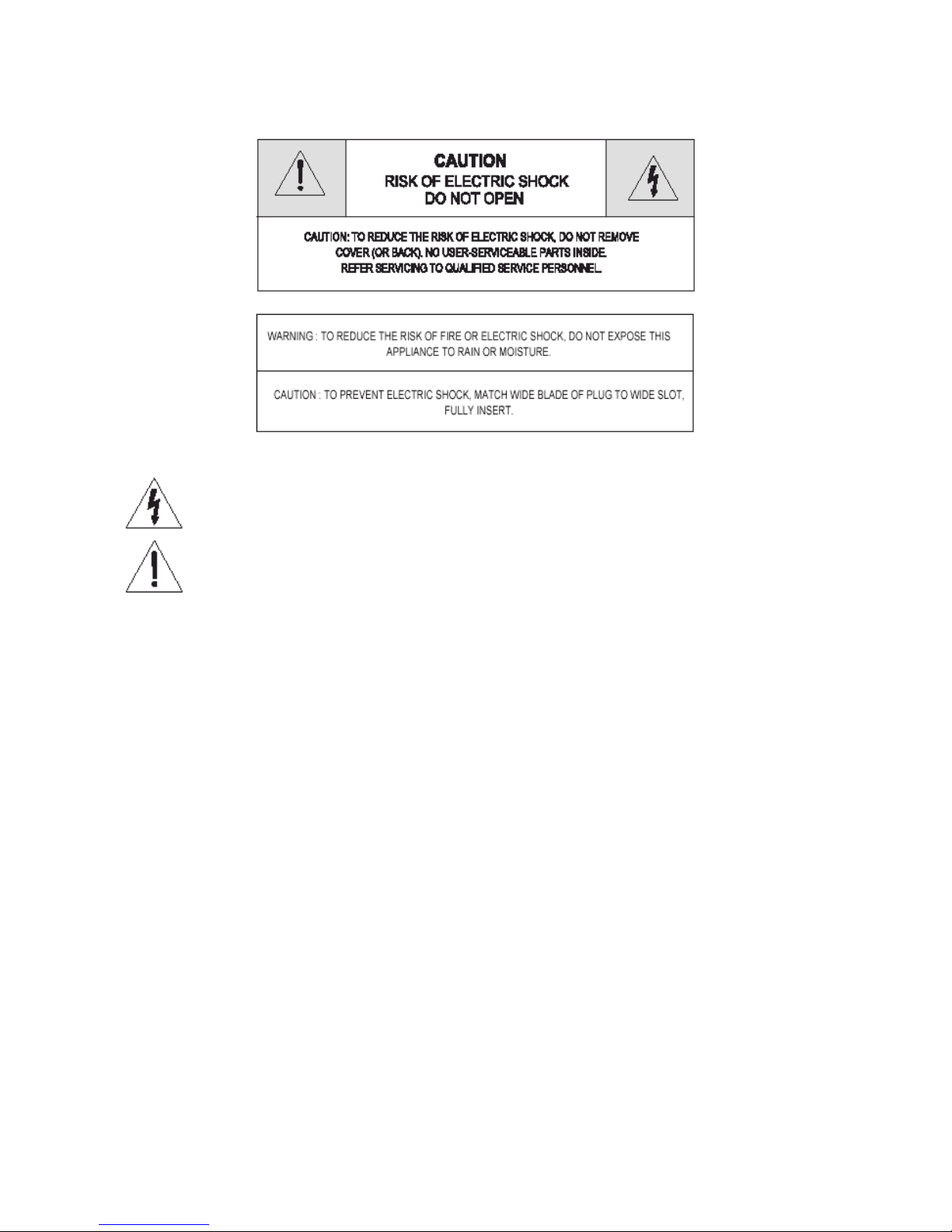
29
SAFETY INFORMATION
The lightning flash with arrowhead symbol, within an equilateral triangle, is intended to alert the
user to the presence of uninsulated “dangerous voltage” within the product’s enclosure that may
be of sufficient magnitude to constitute a risk of electric shock.
The exclamation mark within an equilateral triangle in intended to alert the user to the presence of
important operating and servicing instruction in the literature accompanying the appliance.
IMPORTANT SAFEGUARDS
In addition to the careful attention devoted to quality standards in the manufacture of your video product,
safety is a major factor in the design of every instrument. However, safety is your responsibility too. This
sheet lists important information that will help to assume your enjoyment and proper use of the video product
and accessory equipment. Please read them carefully before operating and using your video product.
INSTALLATION
23. Read and Follow Instruction – All the safety and operating instructions should be read before the
video product is operated. Follow all operating instructions.
24. Retain Instructions – The safety and operating instructions should be retained for future reference.
25. Heed Warnings – Comply with all warnings on the video product and the operating instructions .
26. Polarization – This video product is equipped with a polarized alternating-current line plug (a plug
having one blade wide wider than the other). This plug will the power outlet only one way. This is a
safety feature. If you are unable to insert the plug fully into the outlet, try reversing the plug. If the
plug still fails to fit, contact your electrician to replace your obsolete outlet. To prevent electric
shock, do not use this polarized plug with an extension cord, receptacle or other outlet unless the
blades can be fully inserted without blade exposure. If you need an extension cord, use a polarized
cord..
27. Power Sources – This video product should be operated only from the type of power source
indicated on the marking label. If you are not sure of the type of power supply to your home,
consult your video dealer or local power company. For video products intended to operate from
battery power, or other sources, refer to the operating instructions.
28. Overloading – Do not overload wall outlast of extension cord as this can result in a risk of fire or
electric shock. Overloaded AC outlets, extension cords, frayed power cord, damaged or cracked
wire insulation, and broken plug are dangerous. They may result in a shock or fire hazard.
Periodically examine the cord, and if its appearance indicates damage or deteriorated insulation,
have it replaced by your service technician.
Page 38

30
29. Power – Cord Protection – Power supply cords should be routed so that they are not likely to be
walked on or pinched by items placed upon or against them, paying particular attention to cords at
plugs, convenience receptacles, and the point where they exit from the video product.
30. Ventilation – Slots and openings in the case are provided for ventilation to ensure reliable operation
of the video product and to protect it from overheating. These openings must not be blocked of
covered. The opening should never be blocked by placing the video product on a bed, sofa, rug, or
other similar surface. This video product should not be placed in a built-in installation such as
bookcase or rack unless proper ventilation is provided or the video product manufacturer’s
instructions have been followed.
31. Attachments – Do not use attachments unless recommended by the video product manufacturer as
they may cause a hazard.
32. Water and Moisture - Do not use this video product near water – for example, near a bath tub,
wash bowl, kitchen sink or laundry tub, in a wet basement, or near a swimming pool and the like.
Caution: Maintain electrical safety. Power line operated equipment or accessories connected to this
unit should bear the UL listing mark or CSA certification mark on the accessory itself and should
not be modified so as to defeat the safety features. This will help avoid any potential hazard from
electrical shock or fire. If in doubt, contact qualified service personnel..
33. Accessories - Do not place this video product on unstable cart, stand, tripod, racket, or table. The
video product may fall, causing serious injury to a child or adult as well as serious damage to the
video product. Use this video product only with a cart, stand, bracket, or table recommended by the
manufacturer or sold with the video product. Any mounting of the product should follow the
manufacturer’s instructions and mounting accessory recommended by the manufacturer.
34. A video product and cart combination should be moved with care. Quick stops, excessive force,
and uneven surfaces may cause the video product and car combination to overturn.
35. Power Lines – An outside antenna system should not be located in the vicinity of overhead power
lines, other electric light or power circuits, or where it can fall into such power lines or circuits.
When installing an outside antenna system, extreme care should be taken to keep from touching or
approaching such power lines or circuits as contact with them might be fatal. Installing an outdoor
antenna can be hazardous and should be left to a professional antenna installer.
USE
36. Cleaning – Unplug this video product from the wall outlet before cleaning. Do not use liquid
cleaners or aerosol cleaners. Use a damp cloth for cleaning.
37. Object and Liquid Entry – Never push objects of any kind into this video product through openings
as they may touch dangerous voltage points or “shout-out” parts that could result in a fire or electric
shock. Never spill liquid of any kind on the video product.
38. Lightning – For added protection for this video product during a lightning storm, or when it is left
unattended and unused for long periods of time, unplug it from the wall outlet and disconnect the
antenna or cable system. This will prevent damage to the video product due to lightning and power
line surges.
SERVICE
39. Servicing – Do not attempt to service this video product yourself as opening or removing covers
may expose you to dangerous voltage or other hazards. Refer all servicing to qualified personnel.
40. Conditions Requiring Service – Unplug this video product from the wall outlet and refer servicing to
qualified personnel under the following conditions.
G. When the power – supply cord or plug is damaged.
H. If liquid has been spilled, or objects have fallen into the video product.
I. If the video product has been exposed to rain or water.
J. If the video product not operate normally by following the operating instructions. Adjust only those
controls that are covered by the operating instructions. Improper adjustment of other controls may
result in damage and will often require extensive work by a qualified technician to restore the video
product to its normal operation.
K. If the video product has been dropped or the cabinet has been damaged.
L. When the video product exhibits a distinct change in performance – this indicates a need for service.
41. Replacement parts – When replacement parts are required, have the service technician verify that
the replacements he uses have the same safety characteristics as the original parts. Use of
replacements specified by the video product manufacturer can prevent fire, electric shock, or other
hazards.
Page 39

31
42. Safety Check – Upon completion of any service or repairs to this video product, ask the service
technician to perform safety checks recommended by the manufacturer to determine that video
product is in safe operating condition.
43. Wall or Ceiling Mounting – The product should be mounted to a wall or ceiling only as
recommended by the manufacturer.
44. Heat – The product should be situated away from heat sources such as radiators, heat registers,
stoves, or other products (including amplifiers) that produce heat.
INFORMATION TO THE USER
This equipment has been tested and found to comply with the limits for a Class B digital device, pursuant to
part 15 of the FCC Rules. These limits are designed to provide reasonable protection against harmful
interference in a residential installation. This equipment generates, uses and can radiate radio frequency
energy and, if not installed and used in accordance with the instructions, may cause harmful interference to
radio communications. However, there is no guarantee that interference will not occur in a particular
installation. If this equipment does cause harmful interference to radio or television reception, which can be
determined by turning the equipment off and on, the user is encouraged to try to connect the interference by
one more of the following measures:
- Reorient or relocate the receiving antenna.
- Increase the separation between the equipment and receiver.
- Connect the equipment into an outlet on a circuit different from that to which the receiver is
connected.
- Consult the dealer or an experienced radio/TV technician for help.
WARNING
Changes or modifications not expressly approved by the manufacturer could void the user’s authority to
operate the equipment.
Page 40

32
Indice
Front Panel.....................................................................................................................................33
Locations of controls and indicators (Option)...................................................................................34
Front Panel.....................................................................................................................................34
Back Panel........................................................................................................................................2
Remotre control................................................................................................................................3
Video Cassettes Tapes.........................................................................................................................4
Types of on-screen displays and Display Sequence............................................................................5
Setting the Clock..................................................................................................................................6
Change the On-Screen Display............................................................................................................7
Normal Recording................................................................................................................................8
Program Timer Recording...................................................................................................................9
Alarm Recording................................................................................................................................11
One-Shot Recording...........................................................................................................................12
Link (series) Recording......................................................................................................................12
Autorepeat Recording........................................................................................................................14
Normal Playback................................................................................................................................14
Normal Playback............................................................................................................................14
Tracking Control............................................................................................................................15
Audio Playback..............................................................................................................................15
Special Playback................................................................................................................................15
Picture Search................................................................................................................................15
Still Image......................................................................................................................................15
Vertical Lock Control....................................................................................................................15
Slow...............................................................................................................................................15
Recording Check............................................................................................................................15
Alarm Search..................................................................................................................................16
Alarm Scan.....................................................................................................................................16
Index Search...................................................................................................................................16
Other Functions..................................................................................................................................17
Tape Counter (Zero Search)...........................................................................................................17
Setting the Security Lock (Set Lock).............................................................................................17
Setting the Buzzer..........................................................................................................................18
Setting the Video Mode.................................................................................................................18
Checking The Alarm Recording Times.........................................................................................19
Checking Power Fail Recall...........................................................................................................19
Checking Usage Duration..............................................................................................................19
Daily Inspection.................................................................................................................................21
Troubleshooting Guide......................................................................................................................23
Specifications.....................................................................................................................................25
Page 41

33
Locations of controls and indicators
Front Panel
22. Cassette Loading Slot.
23. REC/Play Speed (▲) Button (SET + Button).
24. REC/Play Speed (▼) Button (SET – Button).
25. REC Check Button.
26. Display Button.
27. Audio On Button.
28. Menu Button.
29. Shift (▼) / Tracking (-) Button.
30. Shift (►) / Tracking (+) Button.
31. RMC (Remote Controller) Lock Switch.
32. SET Lock Switch.
33. Reset Button.
34. Pause/Still Button.
35. Power/Timer Button.
36. REC Button.
37. Stop/Eject Button.
38. Counter Button.
39. Clear Button.
40. Play Button.
41. REW Button (Slow -): See the p30.
42. FF Button (Slow +): See the p30.
Page 42

34
Fermo
immagine
Rallentatore 1
Rallentatore 2
Rallentatore 3
Riproduzione
Avanti 1
Avanti 2
Indietro 1
Indietro 2
Locations of controls and indicators (Option)
Front Panel
1. Cassette Loading Slot.
2. REC/Play Speed (▲) Button (SET +
Button).
3. REC/Play Speed (▼) Button (SET –
Button).
4. REC Check Button.
5. Display Button.
6. Audio On Button.
7. Menu Button.
8. Shift (▼) / Tracking (-) Button.
9. Shift (►) / Tracking (+) Button.
10. RMC (Remote Controller) Lock Switch.
11. SET Lock Switch.
12. Reset Button.
13. Pause/Still Button.
14. Power/Timer Button.
15. REC Button.
16. Stop/Eject Button.
17. Counter Button.
18. Clear Button.
19. Play Button.
20. F.ADV Button: See the p30.
21. Shuttle Switch: See the p30
HOW TO USE THE SHUTTLE RING
The shuttle ring is the outer dial. When the VCR is in STOP mode, the shuttle ring can be rotated to the left
or right then released, and the VCR will engage in the REWIND or FAST FORWARD function. While in the
REWIND or FAST FORWARD mode, the shuttle ring can be rotated and held to engage the LOGIC search
mode. Releasing the shuttle ring returns it to the REWIND or FAST FORWARD function.
DURING STILL MODE
When a picture is in still mode, the video can viewed at variable speeds, including slow motion, by rotating
and holding the shuttle ring at different positions. The figure on the right illustrates the action that will occur at
various positions. The VCR returns to the still mode upon release of the shuttle ring.
SHUTTLE RING FEATURES
- In the sill mode: rotate the shuttle ring,
variable speed can be adjusted from slow to
search (normal play, double time speed play)
in the direction of forward (or reverse).
- In the stop mode: rotate and release the
shuttle ring to rewind or fast forward the tape.
- In the normal playback mode: double time
speed and forward search in the direction of
forward (the same function in the direction
reverse).
Page 43

1
Digital LED Displays
1. Cassette indicator:
Comes on when a cassette is loaded.
2. Mode Display.
Tape Counter Display (ex_ 10:
Hour, 59: Minute)
Maximum Hour: 19
Maximum Minute: 59
Alarm Counter Display (ex_ A:
Alarm, 32: Alarm No.)
Play/Rec Speed Display (ex_
960H: Play/Recording Speed)
Time Display (ex_ 7: Hour, 07:
Minutes)
Error Display (ex_ E: Error, 02:
Error No.)
E-01: The cassette cannot be
loaded or unloaded.
E-02: The tape stops.
E-03: The drum can not rotate
properly.
E-04: The tape is cut/broken.
Audio On Display (ex_ A:
Audio, 18H: Play Speed)
1shot Rec Display
12. Operation Indicators
They display the actual operation mode.
Operation Mode Indicator Operation Mode Indicator
Record (REC)
REC +
Alarm Record
+ REC
Playback (play)
STILL/PAUSE
Fast Forward (FF)
Rewind (REW)
CUE (CUE)
Review (REVIEW)
Slow
(Pause Still + FF,
Pause STILL + REW)
13. Record check indicator: REC
Flashes on during record check.
14. Time Recording indicator:
Comes on when in timer recording stand-by mode, or during a timer recording.
15. SET LOCK SW indicator:
Page 44

2
Comes on when the SET LOCK SW is set to the “ON” position.
16. Alarm indicator:
Flashes on when an alarm is being recorded and stop flashing after alarm recording.
17. PWR indicator: PWR
It indicates the existence of power on.
18. L.REC Indicator: L.REC
Comes on when “YES” is selected in the menu for the link recording.
19. R.REC Indicator: R.REC
Comes on when “YES” is selected in the menu for the repeat recording.
20. RMC.L Indicator: RMC.L
Comes on when the RMC (Remote Controller) LOCK SW is set to the “ON” position.
21. SPD Indicator: SPD
It indicates the recording speed on the tape.
22. CNT Indicator: CNT
It indicates the relative position on the tape.
Back Panel
15. AC Power
16. MIC (microphone input) Jack Option
17. Video OUT Jack
18. Video IN Jack
19. Audio OUT Jack
20. Audio IN Jack
21. 1Shot Rec Terminal
22. Tape END Terminal
23. Link OUT Terminal
24. Link IN Terminal
25. Link IN Terminal
26. Alarm OUT Terminal
27. Alarm IN Terminal
28. GND Terminal
Page 45
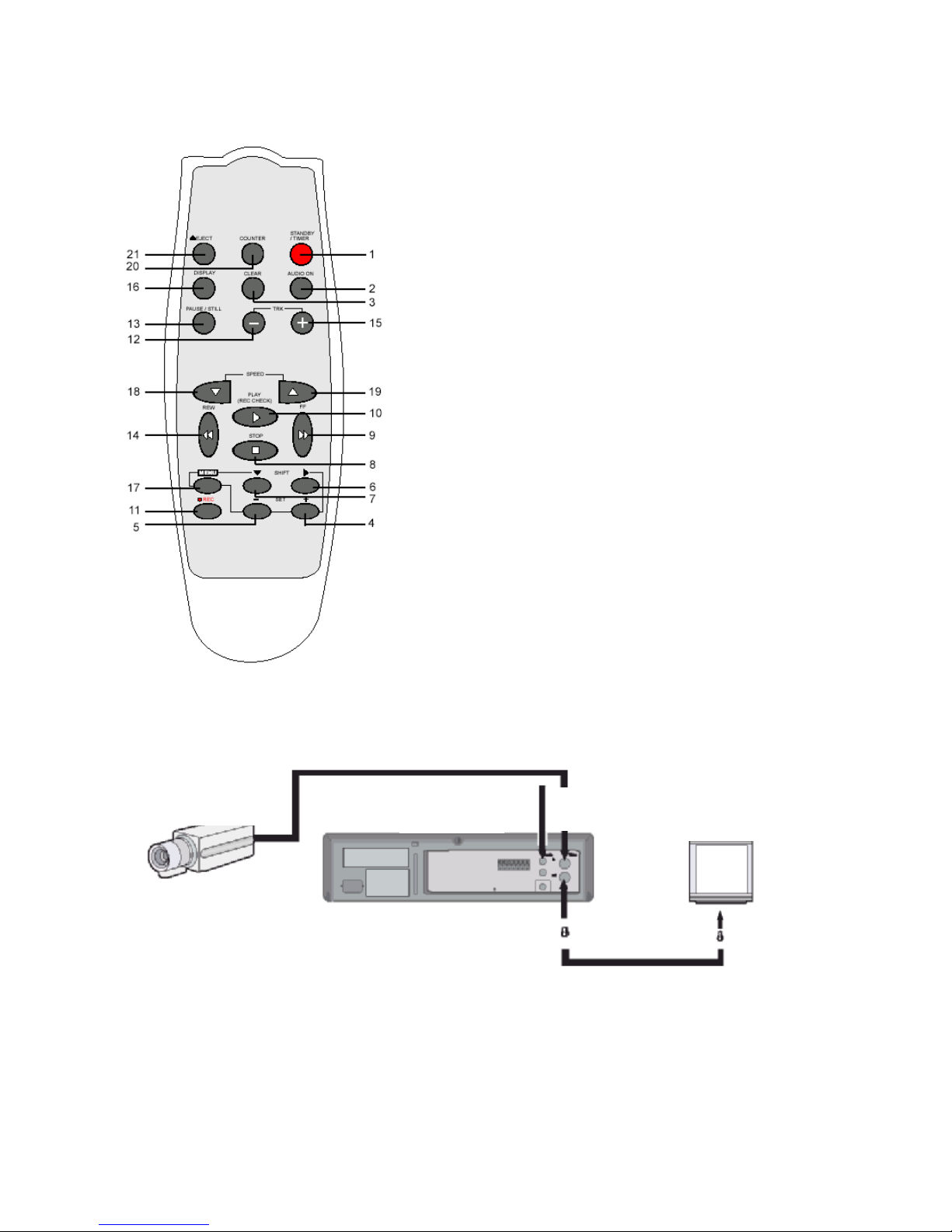
3
Remotre control
1. Power/timer Button
2. Audio On Button
3. Clear Button
4. SET + Button
5. SET– Button
6. Shift ► Button (Move cursor or select)
7. Shift ▼ Button (Move cursor or select)
8. Stop ■ Button
9. FF ►► Button (Slow +)
10. Play ► Button (Rec Check Button)
11. ● REC Button
12. Tracking– Button
13. PAUSE/STILL Button
14. REW ◄◄ Button (slow -)
15. Tracking+ Button
16. Display Button
17. Menu Button
18. REC/Play Speed ▼ Button (Down)
19. REC/Play Speed ▲ Button (Up)
20. Counter Button
21. Eject Button
Connections
Connect the video camera and monitor TV as shown in the figure below.
NOTE: Make sure to turn the power off on all devices before making the connections.
o For more details, please refer to the manuals accompanying all other devices. If the connections are
not made properly, it may cause a fire or damage the equipment.
Video camera (sold
separately)
From an external
Audio source
To Video OUT
Terminal
To Video IN
Terminal
Monitor TV (sold
separately)
Page 46

4
Power Cord Installation
Insert the plug of the power cord into an outlet.
Video Cassettes Tapes
Use only video cassette tapes bearing the VHS logo.
This VCR was primarily designed for use with cassette tapes. It
is recommended to use VHS video cassette tapes for optimal
performance.
Handling Cassette Tapes
Cassette tapes should always be stored vertically in their cases,
away from high temperature, magnetic fields, direct sunlight,
dirt, dust and locations subject to mold formation.
Do not tamper with the cassette mechanism.
Never touch the tape with your fingers.
Protect cassette tapes from shocks or strong vibrations.
To protect your recordings
After having recorded a tape, if you wish to keep the recording,
use a flat head screwdriver to break off the erasure-prevention
tab on the cassette.
To record again on a tape without erasure-prevention tab, cover
the hole with adhesive tape.
o If you try to record on a cassette
without the erasure prevention tab,
the VCR will eject the cassette
o If the TIMER button is pressed
when a cassette without the erasure
prevention tab is loaded, the VCR will
eject the cassette, the timer recording
indicator ( ) will start flashing if
“YES” is set in the menu for buzzer.
o When the cassette is loaded, the
cassette indicator will light on the
display panel.
o The counter display will switch to
the reset counter “0H 00M 00S”
display on the monitor screen (“0H
00M” on the display panel.)
Erasure prevention tab
To prevent accidental erasure, remove the tab after recording.
To record again, cover the hole with vinyl tape.
Loading
Place the cassette, label side up in the loading slot. Gently push the center of the
cassette until it is loaded automatically.
Unloading
In Stop mode, press the Eject button. The cassette is
automatically ejected
o Do not insert any object in the
cassette loading slot, as that may
cause injury and damage to the
VCR
o If your hand gets stuck in the
cassette loading slot, unplug the
power cord and consult the dealer
where the unit was bought.
o Do not forcibly pull the hand out as
that may cause severe injuries.
Page 47
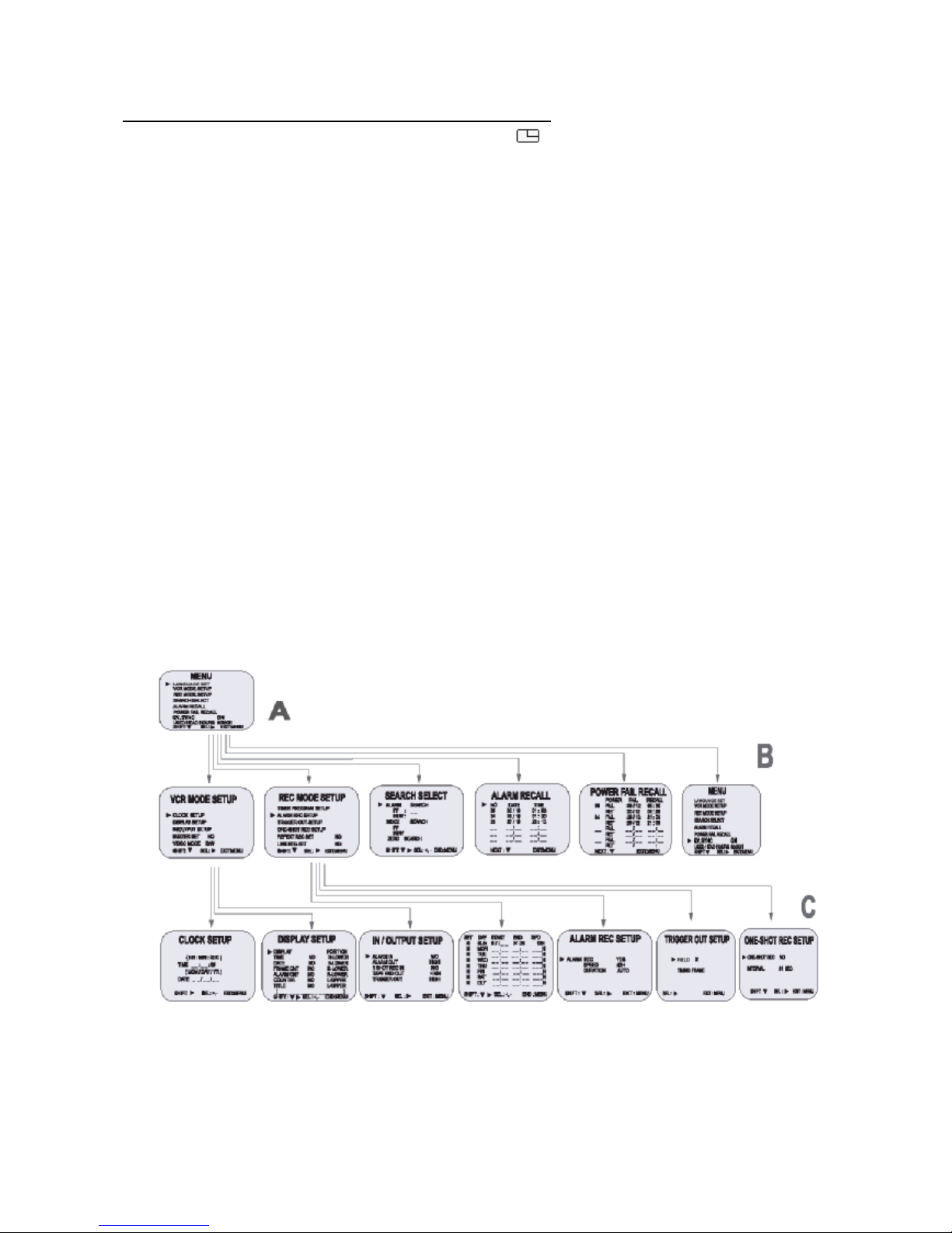
5
Types of on-screen displays and Display Sequence
• If the VCR is in timer recording stand-by mode (the indicator is displayed on the display panel),
the on-screen display will not be available.
First press the Power/Timer button, to cancel the recording stand-by mode, the proceed with the
VCR programming.
When finished, press the Power/Timer button again to return the VCR to timer recording stand-by
mode.
• When a menu is displayed, recording will not be possible.
• Press the Menu button three times, the setting procedure is now completed then the normal screen
is displayed.
• During recording or playback the menus cannot be displayed.
A
§ Press the MENU button (First time)
§ Press the SHIFT ▼ button to move the arrow ► downward for the desired item.
§ Press the SHIFT ► button to select the desired item, then the desired is displayed.
§ Press the MENU button to return to the normal screen from the initial menu.
B
§ Press the SHIFT ► button to select the desired item.
§ Press the SET – (or +) button to set or press the SHIFT ► to (select) “YES” or “NO”.
§ Press the MENU to return to the initial menu.
C
§ Press the SHIFT ► (or SHIFT ▼) button to select the desired item.
§ Press the SET – (or +) button to set or press the SHIFT ► button to select.
§ Press the MENU button to return to the previous menu.
INITIAL
MENU
SECOND MENU
GROUP
THIRD MENU
GROUP
Page 48
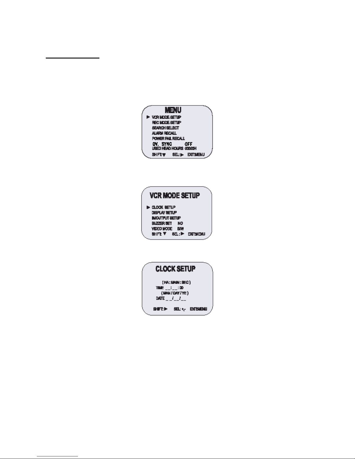
6
Setting the Clock
Example: To set the clock to April 12, 2004 at9:30
Clock Setting
13. Turn the power on to all devices used.
14. Press the MENU button, the initial MENU is displayed.
The arrow mark (►) is located in “VCR Mode Setup”.
15. Press the SHIFT ► button, the VCR mode setup menu is displayed. The arrow mark (►) is located
in “Clock Setup”.
16. Press the SHIFT ► button, the Clock Setup menu is displayed.
17. Press the SET – (or +) button to set the hours (ex. 09), then press the SHIFT ► button.
18. Press the SET – (or +) button to set the minutes (ex. 30), then press the SHIFT ► button.
19. The seconds are already set to “00”.
20. Press the SHIFT ► button.
21. Press the SET – (or +) button to set the month (ex. 04), then press the SHIFT ► button.
22. Press the SET – (or +) button to set the day (ex. 12), then press the SHIFT ► button.
23. Press the SET – (or +) button to set the year (ex. 04 for 2004).
• The last 2 digits only are displayed.
• The day of the week is set automatically.
24. Press the MENU button three times, the normal screen is displayed.
• The setting procedure is now complete.
Page 49
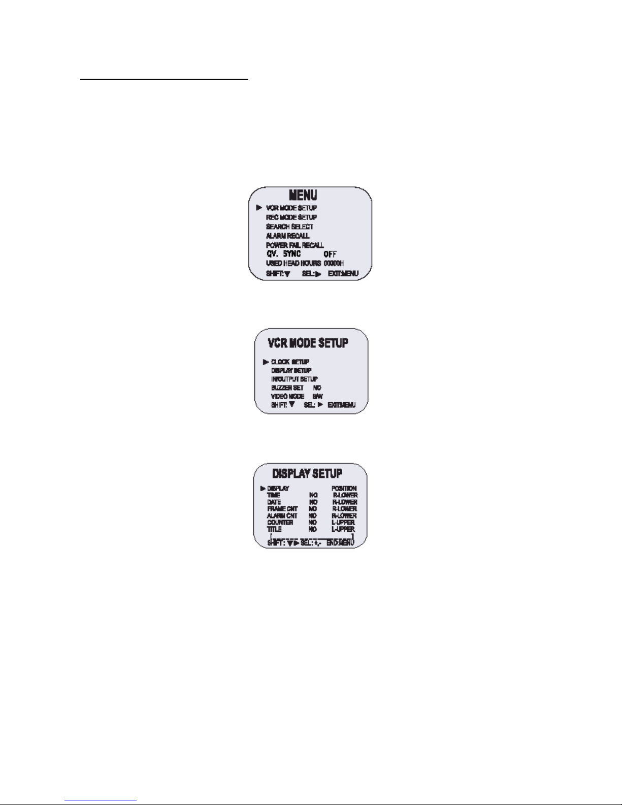
7
Change the On-Screen Display
Selecting the On-screen Display
You can select to display the or time, date, frame counter, alarma counter, counter title.
11. Turn the power on to all devices.
12. Press the MENU button.
The initial MENU is displayed.
• The arrow mark (►) is located in “VCR MODE SETUP”.
• If a distortion may appear on the top of the screen when VCR is connected to a Multi-plexer, QV.
Sync can be switched between ON and OFF during playback by pressing SEL.
13. Press the SHIFT ► button to select VCR MODE SETUP, then the VCR MODE SETUP menu is
displayed.
14. Press the SHIFT ▼ button until the arrow mark (►) points “Display setup”.
15. Press the SHIFT ► button to select Display Setup, then the DISPLAY SETUP menu is displayed.
16. Press the SET – (or +) button to set “YES” for the functions described below:
TIME The time is displayed.
DATE The Month – Day – Year is displayed.
FRAME CNT The number of frames is displayed.
ALARM CNT The number of alarms is displayed.
COUNTER The counter is displayed.
TITLE The title is displayed.
• A maximum of 20 characters can be used. (alphabet, number or spaces).
17. Press the SHIFT ► button to set the display position.
18. Press the SET – (or +) button to set the position of the time, date, frame cnt, alarm cnt to “L-Bottom
(or R-Bottom)”.
• If one of 4 items is set, the position of 4 items is changed identically.
Page 50

8
19. Press the SET – (or +) button to set the position of the counter and title to “C-Upper” (or “R-Upper” or
“L-Upper”).
If one of 2 items is set, the position of 2 items is changed identically.
20. Press the MENU button three times, the normal screen is displayed.
The setting procedure is now complete.
o The items for which “YES” is set are recorded..
The items for which “NO” is set at step 6 above are not recorded.
Normal Recording
Normal recording
6. Turn the power on to all devices used.
7. Load a cassette tape with erasure prevention tab in place.
8. Press the REC/PLAY SPEED ▼ (or ▲) button to set the recording speed.
• The recording speed is displayed on-screen and on the display panel..
• If you don’t want to record the recording speed, counter title, time, date, etc., press the DISPLAY
button, then start recording..
9. Press the REC button.
• The “REC” indicator is displayed on the display panel and recording starts..
10. To stop recording, press the STOP button.
Recording Speed
Recording Speed
E-180 E-240
Recording
Intervals
Registrazione
campo/secondi
Registrazione
audio
Avanzamento del
nastro
3H 4H 1/60 sec. 50 YES Continuous
6H 8H 1/60 sec. 50 YES Continuous
18H 24H 3/60 sec. 20 YES Continuous
30H 40H 15/60 sec. 10 YES Continuous
48H 68H 24/60 sec. 2,9 NO Intermittent
72H 100H 36/60 sec. 2 NO Intermittent
96H 132H 48/60 sec. 1.5 NO Intermittent
120H 164H 1 sec. 1.2 NO Intermittent
168H 228H 1.4 sec. 0.87 NO Intermittent
240H 324H 2 sec. 0.61 NO Intermittent
360H 484H 3 sec. 0.41 NO Intermittent
480H 644H 4 sec. 0.31 NO Intermittent
720H 964H 6 sec. 0.20 NO Intermittent
960H 1284H 8 sec. 0.15 NO Intermittent
1280H 1708H 10.7 sec. 0.1 NO Intermittent
v (SP) means to recorded by SP heads.
v (EP) means to recorded by EP heads.
v 12H, 24H mode (Pb only).
o If the Repeat Rec Set is set to “NO” in the REC MODE SET menu, recording will continue to the end
of the tape, then stop and the tape will be ejected.
o A tape recording on this VCR cannot be played back on another make of time lapse VCR.
o If you press on the REC button and the loaded cassette has no erasure prevention tab, the VCR will
eject the cassette.
o During recording, the Menu button will not function (the menu cannot be accessed).
Record Pause
Recording can be interrupted temporarily.
3. Press the PAUSE/STILL button durino recording.
The “REC” e “II” indicators are displayed on the display panel.
4. To resume recording, press the REC button, or press the PAUSE/STILL button again.
o If you playback the recording part where recording check was performed, noise may appear..
Page 51

9
o If you change the recording speed during recording, noise or missing signal may result.
o During pause, the image appears on screen but it is not recorded.
o If a recording pause continues for 5 minutes or more, the VCR will go into stop mode to avoid
damage to the tape.
Program Timer Recording
There are two program timer recording methods, daily recording or recording on certain days of multiple
weeks (weekly recording).
Example 1: To record on every Thurday from 10:00 to 18:00, in 24-hour mode (recording speed).
14. Make sure that the set date and time are correct.
15. Load a cassette tape with erasure prevention tab in place.
16. Press the MENU, SHIFT ▼, SHIFT ►, SHIFT ► button in sequence to display the TIMER PROGRAM
SETUP menu.
• The white block cursor is on “SUN (Sunday).
17. Press the SHIFT ▼ button, until the cursor in on “THU”.
18. Press the SHIFT ► button.
• The cursor is moved to the recording start hour position .
19. Press the SET – (or +) button to set the recording start hour (ex. 10), then press the SHIFT ► button.
• The cursor is moved to the recording start minutes position.
20. Press the SET – (or +) button to set the recording start minute (ex. 00), then press the SHIFT ► button.
• The cursor is moved to the recording stop hour position.
21. Press the SET – (or +) button to set the recording stop hour (ex. 06), then press the SHIFT ► button.
• The cursor is moved to the recording stop minutes position.
22. Press the SET – (or +) button to set the recording stop minutes (ex. 00), then press the SHIFT ► button.
23. Press the SET – (or +) button to select the recording speed (ex. 24), then press the SHIFT ► button.
• The cursor is moved to the Y/N position.
o If the set stop time is earlier than or the same time as the set start time, the VCR will consider the
stop time to be the following day.
24. Press the SET – (or +) button to select “Y”.
Y Recording will take place
N Recording will not take place
Programmed time recording Example 1
• Repeat steps 4 to 13 to program timer recordings for other days of the week.
• To set one or more timer recordings the same day of the week, press the SHIFT ▼ button, until
the cursor is located in the day of the week for the second recording, then press the SET – (or +)
Page 52
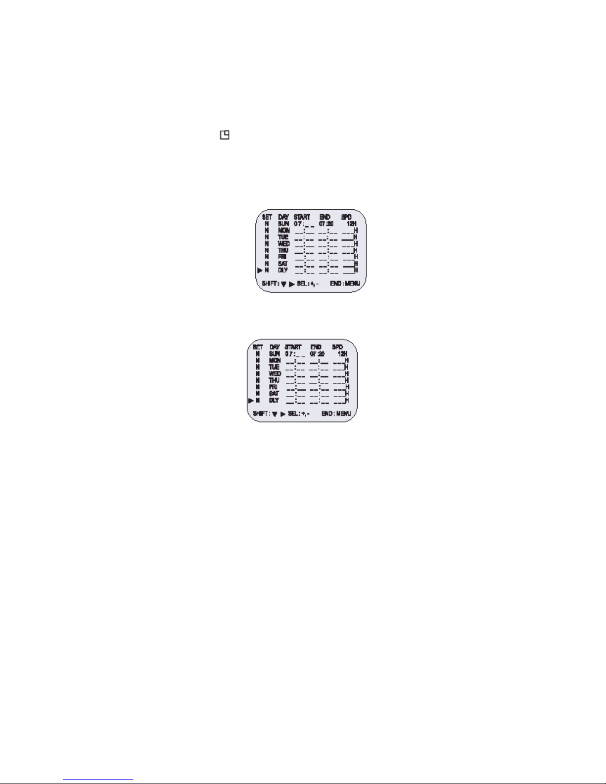
10
button, to set the desired day of the week. With each press of the SET – (or +), the day will
ch’ange as indicated below.
SET -: <-------- direction, SET +: --------> direction
→SUN↔MON↔TUE↔WED↔THU↔FRI↔SAT↔DLY←
25. Press the MENU button three times, the normal screen is displayed.
26. Press the Power/timer button.
The timer recording indicator “ ” will light on the display panel.
The VCR is now in timer recording stand-by mode.
Example 2: To record on every day from 10:00 to 18:00, in 24-hour mode (recording speed).
4. Repeat steps 1-3.
5. Press the SHIFT ▼ button, until the cursori s on “DLY”.
The MENU below is displayed.
6. Repeat steps 5 to 13.
Programmed time recording Example 2
o To modify, cancel timer recording, press the Power/timer button to cancel the timer recording mode.
Changing a Program Timer Recording
5. Press the MENU, SHIFT ▼, SHIFT ►, SHIFT ► buttons in sequence to display the TIMER
PROGRAM SETUP menu.
6. Press the SHIFT ► (or ▼) button, until the cursori s located in the settino to correct.
7. Per correggere l’impostazione, premere il tasto SET – o + (imposta).
• Press the MENU button three times until the normal screen is displayed.
8. Press the Power/Timer button.
To Cancel a Program Timer Recording
6. Repeat steps 1 above.
7. Press the SHIFT ► (or ▼) button until the cursori s located in the “Y” corresponding to the timer
recording to cancel.
8. Press the SET – (or +) to select “N”.
9. Press the MENU button three times until the normal screen is displayed.
10. Press the Power/Timer button.
• The Clear button can erase the programmed timer programmed timer recording in the line that the
cursor is located.
Notes…….
• During timer recording all the buttons on the VCR, except the STOP during timer recording, the
recording will stop. Durino timer recording press the Power/timer button if the buttons do not
respond.
• If there is a power loss, the recording will be interrupted.
Page 53

11
When the power is restored, the recording will resume if the stop time has not yet been reached, and
“PWR” will be flashing on the display panel.
The VCR internal battery is completely charged after the VCR has been connected to an AC power
outlet for 48 hours, and it will maintain all the VCR settings memory for up to 30 days.
Set the timer recordings so that the recording time do not overlap. If they do, the one with the earliest
recording start time will have priority.
• If the cassette tape is ejected while timer recording is set, the buzzer will be hear 5 times (when the
buzzer function is set to “YES”).
Alarm Recording
Alarm Recording Setting
Alarm recording is performed when there is an input (trigger) at the ALARM IN terminal, “ ” is displayed
on the display panel.
10. Mark all necessary connection.
11. Press the MENU, SHIFT ▼, SHIFT ► button in sequenze to display the REC MODE SETUP menu.
12. Press the SHIFT ▼ button until the arrow mark (►) point to Alarm Rec Setup.
13. Press the SHIFT ► button to display the ALARM REC SETUP menu.
14. Press the SHIFT ► button to select “YES” or “NO”.
YES
The alarm recording takes place when there is alarm trigger input.
NO
The alarm recording does not take place.
15. Press the SHIFT ▼ button to set the Alarm speed.
16. Press the SHIFT ► button to select the desired recording speed.
06H 06-hour mode recording
30H 30-hour mode recording
17. Press the SHIFT ▼ button to set the alarm duration.
18. Press the SHIFT ► button to select the desired recording duration.
• Auto: Recording as long as the alarm signal is being input.
• 03/05/10/15/20/25/30/T-end MIN: Recording for the set during (MIN: MINUTE).
• T-END: Recording until the tape end is reached when there is alarm trigger input (Note: In the case
T-END of duration mode set, Repeat recording cannot be performed)..
Program 1
Program 2
Program 3
These portions will not
be recorded.
Page 54
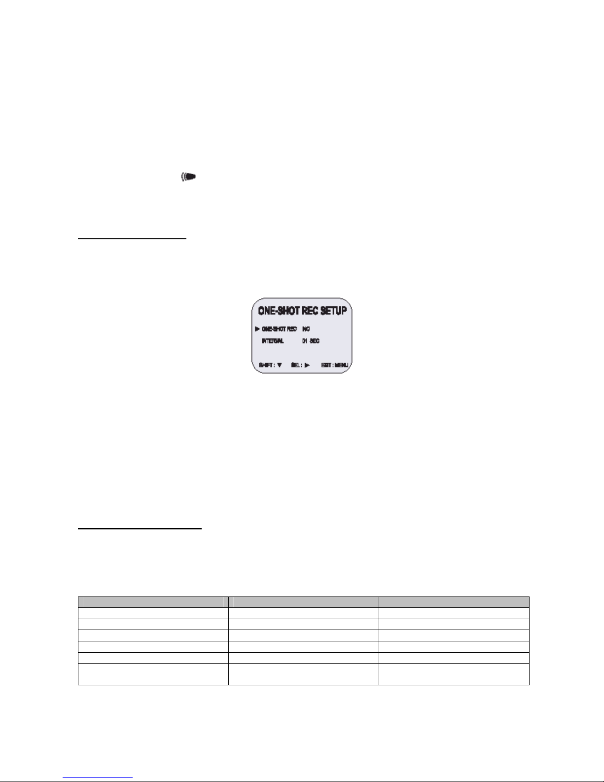
12
o During alarm recording all buttons are disabled except the STOP button. If the STOP button is
pressed, the alarm recording will stop.
o If an alarm trigger is received while alarm recording is in progress, the recording duration for the
second alarm will be calculated from that point.
o When there is a power loss duration alarm recording, if the power is restored set during will continue.
(Note: Alarm counter an increase one more)..
Alarm Recording Counter Display
During alarm recording, “ ” will be flashing on the display panel.
The maximum display number of alarm triggers is “35” at the next alarm recording the counter will indicate
“00”. .
One-Shot Recording
One-Shot Recording Setting
9. Press the MENU, SHIFT ►, SHIFT ►button in sequenze to display the REC MODE SETUP menu.
10. Press the SHIFT ▼ button until the arrow mark (►) point to ONE-SHOT REC SETUP.
11. Press the SHIFT ► button to display the ONE-SHOT REC SETUP menu.
12. Press the SHIFT (►) button to select “YES” or “NO”.
13. Press the SHIFT (▼) button to set the One-Shot interval.
14. Press the SHIFT ► button to select the desired recording interval.
• Interval mode: 01/02/03/05/10/20/30/60/off (sec)
OFF: Interval mode “OFF” means the VCR is set to receive external signals through the 1
SHOT terminal.
15. Press the REC button.
• The “REC” “000H” indicator is displayed on the display panel and recording starts.
• the “1SHOT” is displayed on the monitor.
16. To stop recording, press the STOP button.
Link (series) Recording
Using 2 VCRs or more, the link recording function lets you switch recording from one unit to the next (only
with VCRs of the same model as this one).
Link Recording Setup
5. Connect 2 VCRs or more as illustrated below.
6. Set the following items as indicated.
Item VCR No.1 VCR No.2 and on
Cassette tape Loaded Loaded
Operation mode Stop Stop
Repeat Rec Set NO NO
Link Rec Set YES YES
Timer recording OFF (not set) OFF (not set)
Security lock switch (SET LOCK
switch)
OFF ON
Page 55

13
o Alarm Counter Reset can be performed by pressing the CLEAR key in “Alarm Time” of Initial Menu
screen.
o During Link recording, autorepeat recording or timer recording are not possible.
o If in the REC MOD SET menu, “Link Rec Set” is set to “NO”, Link recording will not be possible.
7. Press the REC button on VCR No.1.
• Recording will start series recording mode.
8. Set the security lock on VCR No.1.
• When the end of the tape on VCR No.1 is reached, the out at the LINK OUT (Series Out)
terminal will switch signal.
This will start recording on VCR No.2, the tape will stop and be ejected on VCR No.1.
Page 56
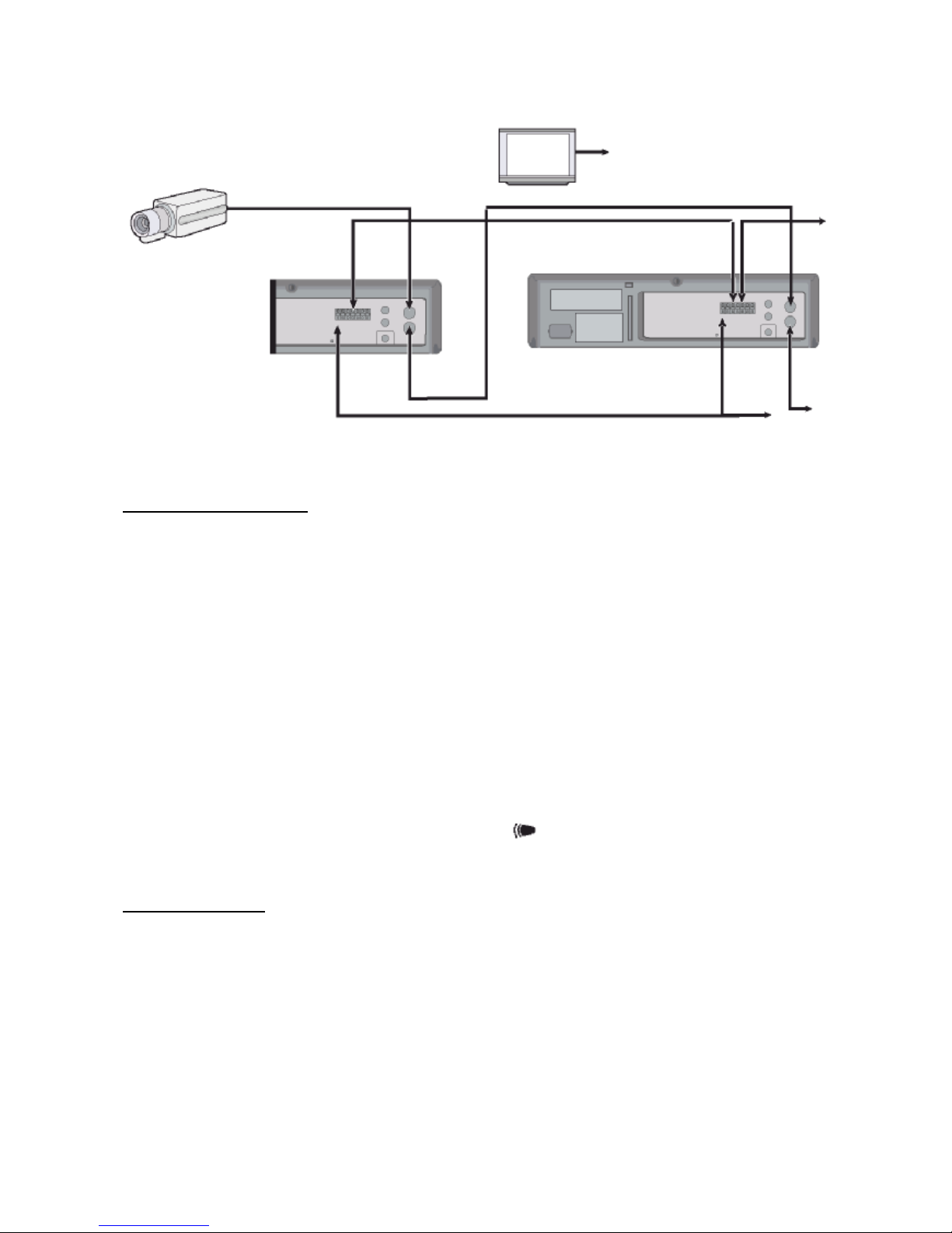
14
Autorepeat Recording
Autorepeat Recording
The same tape can be recorded over many times.
6. Press the MENU, SHIFT ▼, SHIFT ► button in sequence to display the REC MODE SETUP menu.
7. Press the SHIFT ► button to make the arrow mark (►) point to Repeat Rec Set.
8. Press the SHIFT ► button to set the desired autorepeat recording mode.
NO Autorepeat recording doesn’t take place.
YES Autorepeat recording takes place.
“R.REC” will light on the display place.
9. Press the Menu button two times, the normal screen is displayd.
• The setting procedure is now complete.
10. Press the REC button.
• Recording will start. When the tape’s end is reached, the VCR will rewind it to the beginning
regardless of the counter memory, and recording will resume. (Note: In the ALARM REC
SETUP Menu, in the case “T-END” of duration mode set, Repeat Recording cannot be
performed.
o If durino autorepeat recording there is an alarm trigger “ ” is displayed on the display panel and alarm
recording will take place. Autorepeat recording has completed its programmed duration.
Normal Playback
Normal Playback
6. Turn on the power to the TV monitor.
7. Load the video cassette tape.
8. Press the REC/PLAY SPEED ▼ (or ▲) button to select the playback speed.
• The selected playback speed is displayed on the display panel.
• A tape recorded with SP heads can be played in 02-Hour/30-Hour…….
9. Press the PLAY button.
• Playback starts.
• If necessary, adjust thte tracking to eliminate the noise from the picture.
10. To stop playback, press the STOP button.
• To advance or rewind the tape, press the FF/CUE or REW/REVIEW button.
Video camera
Monitor TV
To Video Out
Jack (VCR)
VCR No.1
VCR No.2
To GND
terminal
To Link Out
(Series
Out)
terminal
To Video In
Jack
To GND
terminal
To GND terminal
(VCR No.3)
To Video Out
Jack
To Video Out
Jack
To Link Out
(Series
Out)
terminal
To Video In
Jack
To Link In
(Series In)
terminal
Page 57

15
Tracking Control
If there is noise in the image during playback,
4. While looking at the playback picture, press and hold the TRACKING+ button to minimize
the noise.
5. If it cannot be minimized, press the TRACKING- button.
6. Press the PLAY button in the playback mode.
Audio Playback
Audio playback is only possible in (2, 6, 18, 30-hour) modes. The playback speed has to be the same as the
recording speed, for normal playback of the audio.
For a tape recorded in (2, 6, 18, 30-hour) modes, press the AUDIO ON button after pressing the PLAY
button.
“A” will be displayed to the left of the playback speed on the display panel. Press the AUDIO ON button
again to remove “A”.
o A slow motion effect or accelerated playback effect can be achieved by using a slower or faster playback
speed than the speed used for recording.
Special Playback
Picture Search
3. Press the FF/CUE (or REW/REVIEW) button, during normal playback.
• The image can be seen while the tape is advanced (or rewound) at high speed.
4. To return to normal playback, press the PLAY button.
Still Image
3. Press the PAUSE/STILL button, during normal playback.
• A still image can be viewed.
4. To return to normal playback, press the PLAY button.
• With each press of the PAUSE/STILL button, the still image is advanced one image
(FRAME).
Vertical Lock Control
During still image mode,
3. Press the TRACKING+ button to reduce the vertical rolling of the image.
4. If it cannot be corrected, press the TRACKING- button.
Slow
4. With each press of the FF(F.ADV) button, durino still image mode, the slow speed will change as
indicated below.
1/15 times --------------> 1/20 times -------------> 1/30 times (forward direction)
5. With each press of the REW button, during still image mode, the slow speed will change as indicated
below.
1/15 times --------------> 1/10 times --------------> 1/5 times (reverse direction)
6. To return to normal playback, press the PLAY button.
Recording Check
During recording, press the PLAY/REC CHECK button. The tape will be rewound for about 5 seconds and
slow play mode will be performed.
Page 58
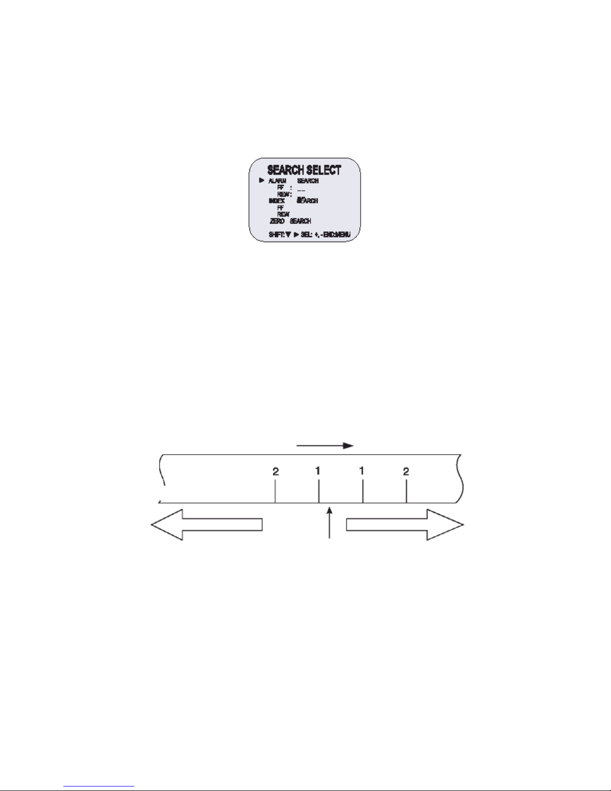
16
The VCR will then return to the previous recording mode.
Alarm Search
5. Press the Menu button to display the initial menu.
6. Press the SHIFT ▼ button to select Search Select, then press the SHIFT ► button to display the
SEARCH SELECT menu.
o During picture search, noise (horizontal bars) will appear in the picture.
o The sound is muted.
o If still mode continues for 5 minutes of more, the VCR will go into stop mode to avoid damaging the tape.
o If the image is unstable (rolling vertically), adjust the Tracking control to correct.
o During recording check operations, recording is suspended momentarily.
7. Move the arrow mark (►) to FF or REW in the Alarm Search mode as you want to search.
8. Press the SET- (or +) button to enter the number of alarm marks you want to search, press the
SHIFT ►button to search forward of in backward.
• The display returns to the normal screen.
• The VCR will locate the desired alarm recording and begin playback.
Alarm Scan
4. Repeat steps 1 to 3.
5. Press the SHIFT ► button to search forward or in riverse without entering a specific alarm number.
• The display returns to the normal screen.
• The VCR will advance (or rewind) the tape at high speed, and playback the first 5 seconds
of every alarm recording.
• To cancel the alarm scan mode, press the STOP button.
6. While the desired recording is being played back, press the PLAY button. Playback will start, and
alarm scan is cancelled.
Index Search
5. Repeat steps 1 to 2.
Playback
Alarm number
Alarm trigger input point
Rewind direction Fast-forward direction
Actual position
Page 59
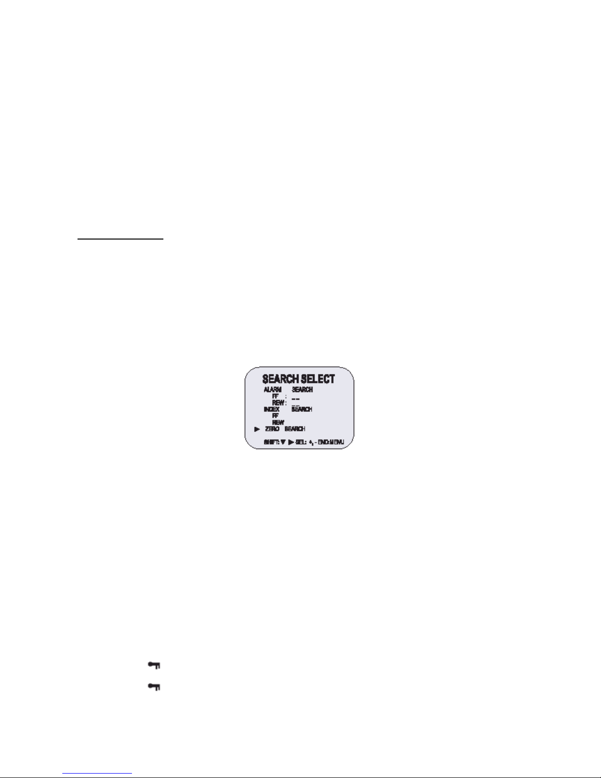
17
6. Move the arrow mark (►) to the FF or REW in the Index Search mode as you want to search.
7. Press the ► button to search forward o in backward.
• The display returns to the normal screen.
• The VCR will advance (or rewind) the tape at high speed and playback the 5 seconds of
every normal recording.
• To cancel the Index Search mode, press the STOP button.
8. While the desired recording is being played back, press the PLAY button.
• Playback will start, and Index Search is cancelled.
o If the Index Search mode, SHIFT ► button should be used to search forward or in backward (Index
FF/REW).
o Please note that when you press CUE 7 button for the quick FF, you can see the noise band on the screen.
o This is not a defect, but a transient phenomenon and this noise will be disappeared soon.
Other Functions
Tape Counter (Zero Search)
Using the counter, it is easy to find a desired recording.
7. Press the CLEAR button, at the beginning of the desired recording.
• The counter will be reset to “0H 00M 00S” (on screen).
• The counter will be reset to “0H 00M” (on the display panel).
8. After recording or playback, press the Menu button to display the initial Menu.
9. Press the SHIFT ▼ button to move the arrow mark (►) to Search Select.
10. Press the SHIFT ► button to display the SEARCH SELECT menu. The SEARCH SELECT menu is
displayed.
11. Press the SHIFT ▼ button to move the arrow mark (►) to Zero Search.
12. Press the SHIFT ► button to search the counter “0H 00M 00S” (“0H 00M” on the display panel).
• The display returns to the normal screen.
• The tape is rewound or advanced to the counter “0H 00M 00S” recording (“0H 00M” on the
display panel).
o When you insert a cassette, the counter always resets to Zero.
o There is no tape counter indication for the blank portions of tape.
o In the 2-hour recording speed mode only, the tape counter indicates real hours, minutes and seconds.
o There may be slight discrepancy between the position shown on the tape counter and the actual tape
position.
o When rewinding the tape past the “0H 00M 00S” (“0H 00M” on the display panel),a minus (-) displayed.
Setting the Security Lock (Set Lock).
The security lock function is designed to prevent accidental stopping of recording if the STOP button is
pressed inadvertently.
3. Set the SET LOCK switch to “ON” position.
• “ ” is displayed on the display panel.
4. To cancel the security lock, se the SET LOCK switch to “OFF” position.
• “ ” will be erased from the display panel.
Setting the Trigger Out Terminal Output
Page 60

18
Synchronization pulses for multiplexers can be obtained from the TRIGGER OUT terminal.
7. Press the MENU button, to display the initial MENU.
8. Press the SHIFT ▼ button to move the arrow mark (►) to REC MODE SETUP.
9. Press the SHIFT ► button to display the TRIGGER OUT SETUP menu.
10. Press the SHIFT ► button to set “FRAME”. With each press of the SHIFT ► button, the setting will
change as indicated below.
11. Press the SHIFT ► button to set the “FRAME”.
• FRAME … 1 pulse is output after each set number frames.
12. Press the MENU button, the normal screen is displayed.
• The setting procedure is now complete.
o While the security lock is engaged, all commands are disabled.
o The security lock should not be engaged while a menu is displayed.
Setting the Buzzer
5. Press the MENU button to display the intial MENU.
6. Press the SHIFT ► button to select VCR MODE SETUP.
The VCR MODE SETUP menu is displayed.
7. Press the SHIFT ▼ button to move the arrow mark (►) to BUZZER SET.
8. Press the SHIFT ► button to set “YES” for the functions described below.
The buzzer will be heard whenever a button is pressed.
Setting the Video Mode
5. Press the MENU button to display the initial MENU.
6. Press the SHIFT ► button to select VCR MODE SETUP.
The VCR MODE SETUP menu is displayed.
7. Press the SHIFT ▼ button to move the arrow mark (►) to VIDEO MODE.
Page 61

19
8. Press the SHIFT ► button to set “COLOR” or “B/W” for the functions described below.
v Note: Set this video mode to “B/W” during playback, recording when a black and white
camera is in use.
v When in the video mode “B/W”, black and white images will be recorded or playback.
o In the following cases, the buzzer will be heard approximately 5 times.
o If the REC button is pressed while a cassette without erasure prevention tab is set.
o If a cassette, without the erasure prevention tab, is loaded while the timer is set.
o If there is a link recording input while a cassette without erasure prevention tab is loaded.
o Se l’utente preme il tasto TIMER e non inserisce alcuna cassetta nel VCR.
o If “NO” is set, the buzzer will not operate.
Checking The Alarm Recording Times
5. Press the MENU button to display the initial MENU.
6. Press the SHIFT ▼ button to move the arrow mark (►) to ALARM RECALL.
7. Press the SHIFT ► button to display the ALARM RECALL menu.
The number of alarm triggers and the 35 most recent alarm recording times are displayed.
8. Press the MENU button twice, the normal screen is displayed.
Checking Power Fail Recall
5. Press the MENU button to display the initial MENU.
6. Press the SHIFT ▼ button to move the arrow mark (►) to POWER FAIL RECALL.
7. Press the SHIFT ► button to display the POWER FAIL RECALL menu.
The number of power losses, and the 35 most recent power loss times are displayed.
8. Press the MENU button twice, the normal screen is displayed.
o The data for the previous alarm recordings, past 35, is erased.
o POWER FAIL……………. The number of power losses and the data and time of the 35 most recent power
losses and recoveries are displayed.
Checking Usage Duration
3. Press the MENU button to display the initial MENU.
USED HEAD HOURS: The video heads usage duration.
Page 62

20
4. Press the MENU button, the normal screen is displayed.
Setting In/Out terminals
8. Press the MENU button to display the initial MENU.
9. Press the SHIFT ► button to display the VCR MODE SETUP menu.
10. Press the SHIFT ▼ button to move the arrow mark (►) to In/Output Setup.
11. Press the SHIFT ► button to display the IN/OUTPUT SETUP menu.
12. Press the SHIFT ▼ button to move the arrow mark (►) for the desired item.
13. Press the SHIFT ► button to set “N/O” or “N/C”, “High” or “Low”.
• N/O: Normally Open.
• N/C: Normally Closed.
14. Press the MENU button three times, the normal screen is displayed.
Quasi-V SYNC
4. Press the MENU button to display the initial MENU.
5. Press the SHIFT ▼ button to move the arrow mark (►) to Q.V SYNK SETUP.
6. Press the sel (►) button unit for the appropriate system is selected. (ON -> OFF).
This function should be turned OFF with using the multiplexer.
(This function should be turned ON with not using the multiplexer).
Attention
In cue, rew state, noise bar could be happen with up and down.
o The Recording Time data cannot be reset even though the reset button is pressed. If the RESET button is
pressed, all data ca be reset except the running time data.
Page 63
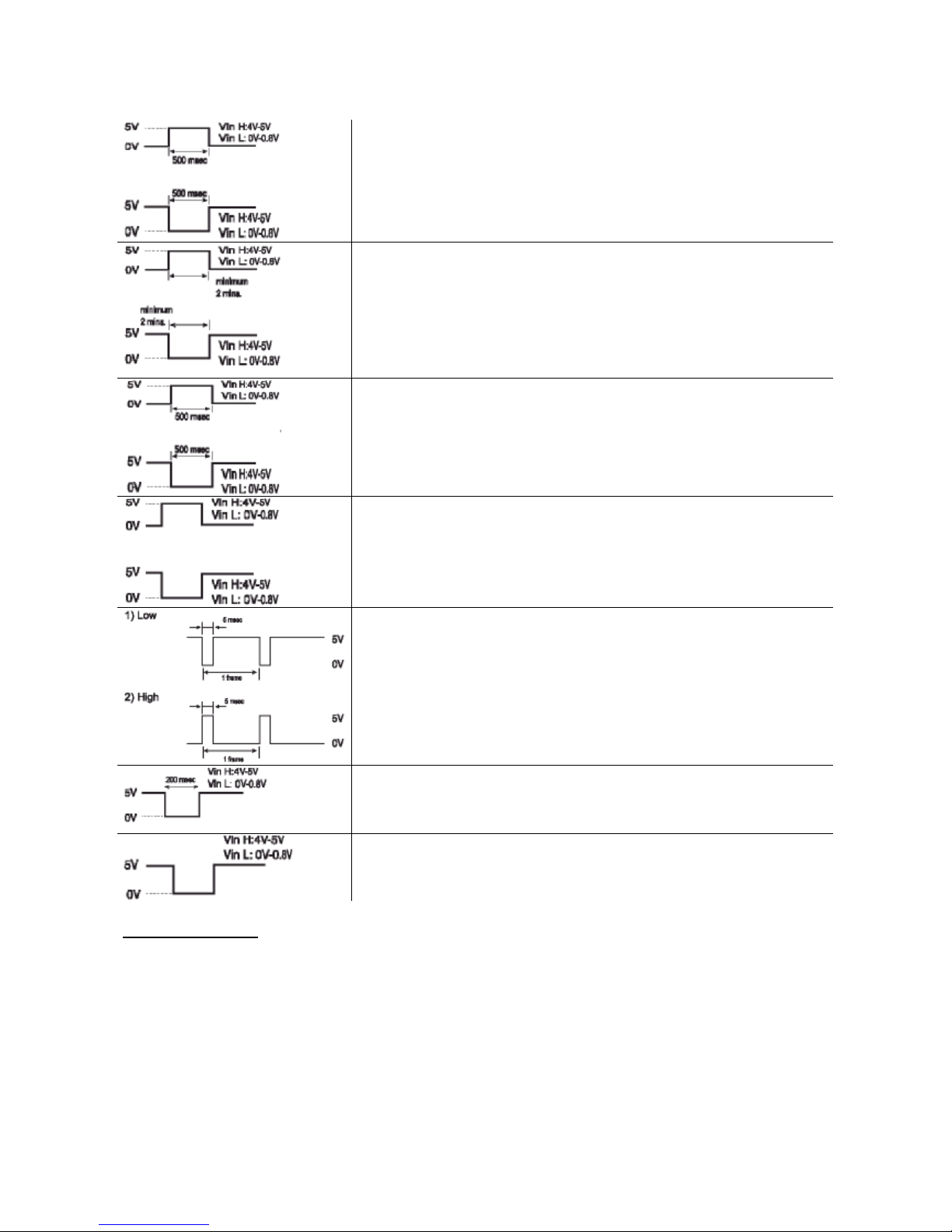
21
ALARM INPUT Terminal
3. “N/C” (Normally CLOSED Switch Circuit). If the input becomes
DC 5V for 500 msec or more, the VCR starti alarm recording.
4. “N/O” (Normally OPEN Switch Circuit). If the input becomes 0V
for 500 msec or morei, the VCR starti alarma recording.
ALARM OUTPUT Terminal
3. “High”: When an alarm input is received and the uniti s recording
the output becomes DC 5V. Once the alarm recording is over,
the output returns to 0V.
4. “Low”: When an alarm input is received and the unit is recording,
the output becomes 0V. Once the alarm recording is over, the
output returns to DC 5V.
1SHOT REC INPUT Terminal
(When an One-Shot Rec Mode setup is in the interval “OFF”).
3. “N/C” (Normally CLOSED Switch Circuit). If the input becomes
DC 5V for 500 msec of more, the VCR starts one-shot recording.
4. “N/O” (Normally OPEN Switch Circuit). If the input becomes 0V
for 500 msec or more, the VCR starts one-shot recording.
TAPE END (OUT) Terminal
3. “High”: Durino recording, when the end of the tape is reached,
the output becomes DC 5V.
4. “Low”: Durino recording, when the end of the tape is reached,
the output becomes DC 0V.
TRIGGER OUTPUT Terminal
While recording, a pulse (DC 5V) is output at the TRIGGER OUT
terminal after each recording period. This terminal is usually connected
to the switch input of the devices like a camera switching unit, or a quad
compressor.
LINK INPUT Terminal
If the input becomes DC 5V for 200 msec or more, the VCR starti link
recording.
LINK OUTPUT Terminal
During recording, when the end of the tape is reached, the output
becomes DC 5V.
Daily Inspection
The following daily inspections are recommended in order to assure long-term and trouble-free operation of
the unit.
The daily inspections are particularly important if using autorepeat recording.
Inspection Procedure
7. Turn on the power to the camera, TV monitor and other connected devices.
8. Check that the image received on the TV monitor is correct.
9. Check that the on-screen display of the date and time is correct.
10. Press the PLAY button and check that the playback image is seconds.
11. Press the PLAY button and check that the playback image is correct.
Page 64

22
• Check in particular playback of time lapse recording (18 or 24 hour mode).
12. Check that the recorded date and time are correct.
o If the security lock is engaged, it has to be released before proceeding with the inspection.
o If any problem is discovered during the inspection, unplug the power cord and consult your dealer.
Page 65

23
Troubleshooting Guide
If the unit does not operate normally when you follow the instructions indicated in the manual, please refer to
the table below.
SYMPTOM POSSIBLE CAUSE CORRECTIVE ACTION
No power.
The power cord is not correctly
connected to the wall outlet.
The unit is in timer recording
standby mode.
- Connect the power cord firmly
into the wall outlet.
- This is normal, not a
malfunction.
No image displayed on the
monitor TV.
The connections are not correct.
The power to the camera and/or
monitor TV is not turned on.
- Check that all connections are
correct.
- Turn all connected devices
power on.
The buttons do not respond.
The unit is in timer recording
standby mode.
Alarm recording.
One-shot recording.
The security lock (SET LOCK) is
engaged.
- Press the Power/Timer button.
- Wait for the alarm recording to
end.
- Press the STOP button for 3
seconds to stop.
- Wait for the one-shot recording
to end.
- Press the STOP button.
- Cancel the security lock.
Unit will not go into record mode.
The loaded cassette has no
erasure prevention tab.
- Load a cassette tape with
erasure prevention tab or cover
the tab hole with adhesive tape.
Autorepeat
“NO” is selected for autorepeat
recording in the REC MODE
SETUP menu.
During autorepeat recording when
there is an alarm input, autorepeat
recording is canceled.
- Be sure to select “YES” for
autorepeat recording.
- Set “YES” again for autorepeat
recording.
Page 66

24
SYMPTOM POSSIBLE CAUSE CORRECTIVE ACTION
Timer recording.
The date and time are not
correct.
The unit is not set to timer
recording standby mode.
“N” is selected tor the TIMER
PROGRAM SETUP menu.
- Set the date and time correctly.
- Press the Power/Timer button
to display “ “ on the display
panel.
- Be sure to select “Y” for the
TIMER PROGRAM SETUP.
Alarm recording.
“NO” is selected for alarm
recording in the ALARM REC
SETUP menu.
- Be sure to select “YES” for
alarm recording.
Noise in the playback picture.
The tracking adjustment is the
wrong.
The video heads need cleaning.
- Adjust it by using the manual
tracking.
- Press the PLAY button in the
playback mode.
- Clean the video heads.
The date and time are ot
recorded.
“NO” is selected for the date and
time in the DISPLAY SET menu.
The date and time go off the ONSCREEN by pressing the
DISPLAY button.
- Be sure to select “YES” for the
display.
- Press the DISPLAY button to
show the date and time.
The cassette tape cannot be
ejected.
Error display (E-01 ~ E-04)
Problem with the system or tape.
- Unplug the power cord then
plug it back in.
Periodic Inspection and Maintenance
Periodic inspection and maintenance should be referred to your dealer. If there is noise in the playback
picture, and it cannot be corrected using the tracking control, it may indicate that the video heads need
cleaning.
The video heads should be cleaned and inspected every 1,000 hours. The video heads usage can be
checked using initial menu, running time.
System down
If the unit does not function at all, try the following:
4. Unplug the power cord then plug it back in.
5. Reset the memory. (Press the RESET button. Under normal conditions, do not touch the RESET
button).
6. If the problem is not corrected after performing steps 1 and 2, consult your dealer.
o Press the RESET button for more than 5 seconds to perform the reset. Running time will not be reset.
Page 67

25
Specifications
General Specifications
Recording method Dual-azimuth 4-head rotating helical scanning system.
Audio recording In 2, 6, 18 and 30 hour mode (E-180).
Tape speed 23.39 m/sec (3 hour mode).
Specified video cassette tape VHS ½ inch video cassette tape.
Recording / playback time 3/6/18/30/48/72/96/120/168/240/360/480/720/960/1280 hour (when
using E-180 tape), 1SHOT (000H).
Hi-Speed Rewind Time Approx. 100 sec (E-180).
Television system PAL color TV system
Video
Recording method Luminance signal: FM recording.
0.8V Down: converted subcarrier phase shift system.
Video input 1Vp-p, BNC, 75Ω, unbalanced.
Video output 1Vp-p, BNC, 75Ω, unbalanced.
Horizontal resolution Black & white mode: more than 300 lines.
Color mode: more than 250 lines.
Audio
Input RCA pin Jack, more than 47kΩ -8.8 dBm, unbalanced.
Output RCA pin Jack, less than 1.5kΩ, -8.8dBm, unbalanced.
Microphone input -60dBm, 3.5mm mini jack, 10kΩ, unbalanced (optional).
Connectors
Alarm input DC 4~5 (open), DC 0~0.8V (closed)/5.7kΩ.
Alarm output DC 4~5 (H), DC 0~0.8V (L)/5.7kΩ.
1SHOT REC INPUT DC 4~5 (open), DC 0~0.8V (closed)/5.7kΩ.
Tape End output DC 4~5 (H), DC 0~0.8V (L)/5.7kΩ.
Link input DC 4~5 (H), DC 0~0.8V (L)/5.7kΩ.
Link output DC 4~5 (H), DC 0~0.8V (L)/5.7kΩ.
Trigger output DC 4~5 (H), DC 0~0.8V (L)/5.7kΩ.
Common 0V (GND)
Other Specifications
Operating temperature range 41°F – 104°F
Operating humidity range 80% or less
Power requirement AC 100- 240V , 50 Hz/60Hz
Power consumption 15W
Dimensions 360(W) X 90(H) X 289 (D)
Weight Approx. 4kg
NOTE: The specifications and external appearance of unit are subject to change without notice.
Page 68

26
 Loading...