

Page 1
NetBlaster ZX470 Series User’s Guide
Fast Ethernet Adapters with Hot-Swap and Rear I/O
for Compact PCI Systems
Page 2

ZNYX Corporation
48421 Milmont Drive
Fremont, CA 94538
USA
Telephone: (510) 249-0800 or (800) 724-0911
Fax: (510) 646-2460
Email: sales@znyx.com
support@znyx.com
Website: www.znyx.com
NetBlaster ZX470 Series User's Guide
Document # DC0117-03
January 28, 2002
© 1999-2002 Z NYX Networks. All rights reser ved worldwide. Information in this document is subject to change without prior notice. ZNYX,
RAIN, RAINlink and NetBlaster are trademarks or registered trademarks of ZNYX Corporation in the United States and/or other countries. All
other marks, trademarks or service marks are the property of their respective owners.
ZNYX may have patents, pending patent applications, trademarks, copyrights or other intellectual property rights covered in the subject matter
of this document. By furnishing this document, ZNYX does not license nor w aive its licens e to those intellec tual property rights except as
expressly pr ovided in a writt en license agr eement from ZNYX. Information i n this document is subject to change without prior notice.
ZNYX NetBlaster 470 Series cPCI Fast Ethernet Adapter User’s Guide Page 2
Page 3

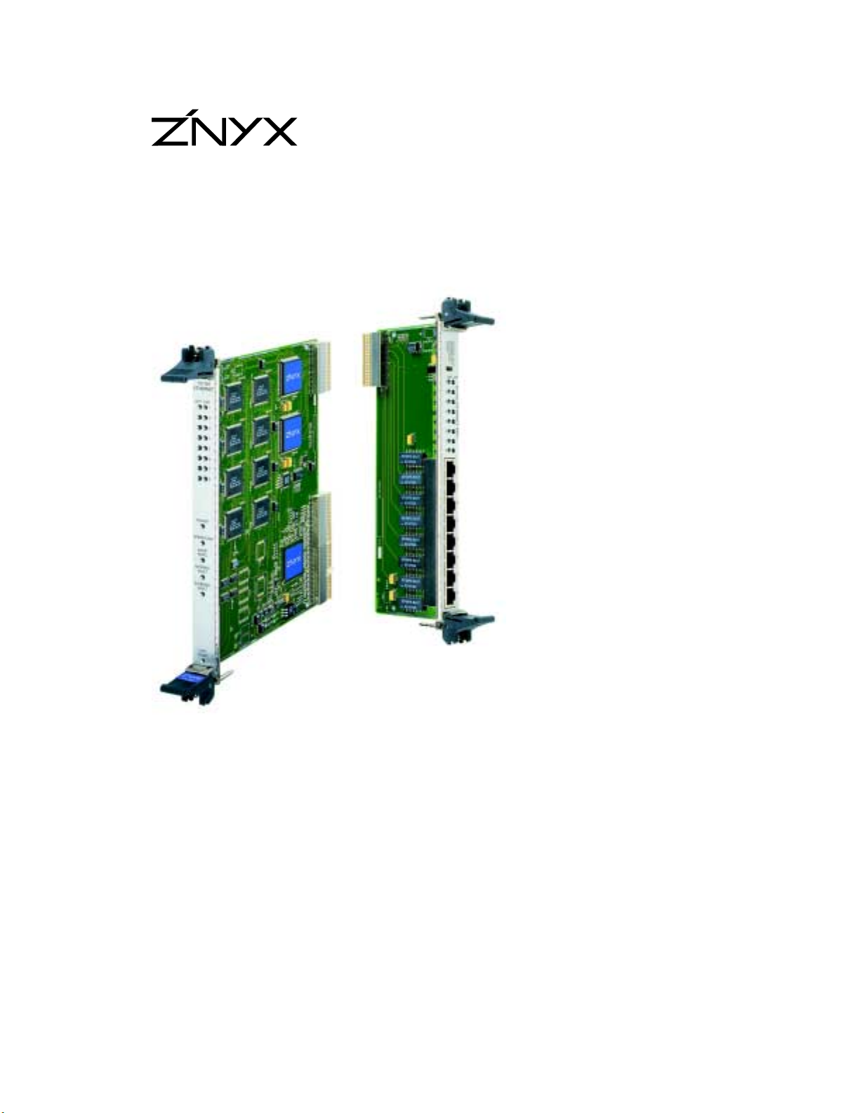
Thank you for choosing the ZNYX NetBlaster 470 Series CompactPCI (cPCI) Fast Ethernet
Adapter. The NetBlaster 470 series is a fully featured product family of carrier Class
CompactPCI Fast Ethernet adapters for high availability applications requiring state-of-the-art
LAN interfaces. The 470 series features:
• Four or Eight channel configurations, 6U form-factor
• Rear I/O via passive 6U x 80mm rear transition module
• Hot swap capability
• 64-bit data bus
• Designed for NEBS Level 3 systems
Your adapter is designed to provide a lifetime of superior service in your system with cPCI slots.
NetBlaster ZX470 Series Fast Ethernet Adapter Models
Model Fast Ethernet Channels cPCI Slot
ZX474 Four 10/100 Mbps 6U
ZX478 Eight 10/100 Mbps 6U
ZX404H Four-channel rear transition module hub
connector (MDI-X)
ZX404HAB Four-channel rear transition module hub
connector (MDI-X) with Type-AB interconnect
ZX408H Eight-channel rear transition module hub
connector (MDI-X)
ZX408HAB Eight-channel rear transition module hub
connector (MDI-X) with Type-AB interconnect
ZX404A Four-channel rear transition module adapter
connector (MDI)
ZX404AAB Four-channel rear transition module adapter
connector (MDI) with Type-AB interconnect
ZX408A Eight-channel rear transition module adapter
connector (MDI)
ZX408AAB Eight-channel rear transition module adapter
connector (MDI) with Type-AB interconnect
6U
6U
6U
6U
6U
6U
6U
6U
Documentation and Software
Documentation and software for the NetBlaster adapter is distributed electronically. You can
retrieve most recent drivers and documentation and drivers from the ZNYX web site,
www.znyx.com
in the driver download section. Please contact ZNYX Customer Support at (800)
724-0911 if you have trouble locating the appropriate driver or installation documentation.
Installation Procedure
There are two basic steps you need to follow to operate the NetBlaster adapter.
1. Install the hardware (NetBlaster adapter and rear transition card).
2. Install the driver.
ZNYX NetBlaster 470 Series cPCI Fast Ethernet Adapter User’s Guide Page 3
Page 4
Hardware Installation
Below are the steps necessary to install a NetBlaster adapter into a standard cPCI system.
Installing the Hardware
This procedure is for installing NetBlaster 470 Series cPCI adapter into a system with an
available 6U cPCI slot. The ZX470 requires a cPCI chassis that supports Rear Panel I/O. You
must also use the appropriate rear transition module for your configuration. Some steps in this
procedure may vary depending on the specific system used. Refer to the system’s documentation
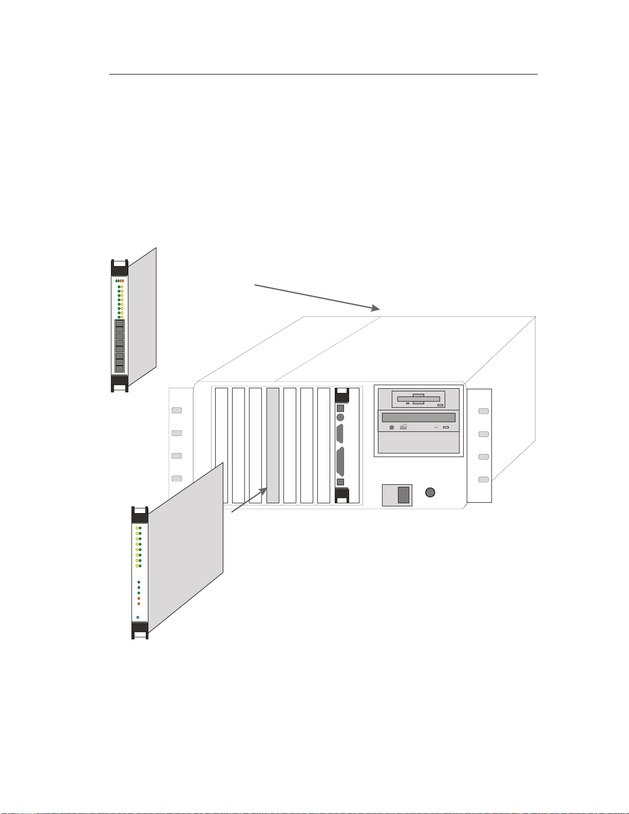
if necessary. The figure below shows the installation of an adapter in a typical system.
ZX408 Rear Transition IO
Place in Corresponding Slot
Ω
0 I
Do not use excessive
force.
!
Observe proper Electro-Static Discharge prevention
procedures at all times. Failure to do so may result
in damage to the PCI Adapter or to the system.
!
ZX478 CPCI Adapter
1. Turn off your system.
2. Discharge any static electricity from your body by touching the metal chassis, or by using an
anti-static wrist strap. If you do not have a ground strap, maintain physical contact with the
case to maintain the same electrical potential with the system.
ZNYX NetBlaster 470 Series cPCI Fast Ethernet Adapter User’s Guide Page 4
Page 5

3. Select an available CompactPCI slot to install the ZNYX NetBlaster adapter. Remove the
slot cover from the front panel. Remove the corresponding cover from the slot on the rear
I/O panel.
4. Insert the ZNYX adapter into the slot. Make certain that you push the adapter straight into
the slot; the bracket and the slot must be properly aligned and the adapter fully seated. The
bracket is well seated when it touches the system case up to the extraction levers.
5. Pull up on the extraction levers to finish seating the adapter, and secure the retention screws.
6. Insert the ZNYX rear transition module into the corresponding slot in the rear panel of the
chassis.
Note: Exercise extreme care when inserting the rear transition card into the chassis.
Improper alignment of the rear transition card connector with the rear panel connector
pins can damage the pins.
Make certain that you push the adapter straight into the slot; the bracket and the slot must
be properly aligned and the adapter fully seated. A good seat is achieved when the bracket
touches the system case, up to the extraction levers.
Rear transition modules are available with
Type-B or Type-AB connectors. Type-AB
connectors include guide pins to aid in properly aligning the rear transition module for
insertion. A backplane that is only
Type-B capable will not accept a Type-AB connector on
the rear transition module.
Type-B Type-AB
7. Pull up on the extraction levers to finish seating the adapter and secure the retention screws.
LAN Cable Connection
The LAN cable must be properly attached to a functioning network for the adapter to operate.
100 Mbps connections require Category 5 cabling. here are two ways to connect the system using
twisted pair: (1) system to system; (2) direct system to hub or switch. You can connect your
adapter directly to another system with a null cable. A null cable, or crossover cable, “crosses
over” transmit and receive pairs.
You can connect your adapter directly to a hub or switch with an unshielded twisted-pair (UTP)
cable. Make certain that the cable length is within the minimum and maximum length restrictions
for Ethernet, or you could experience signal or data loss.
ZNYX NetBlaster 470 Series cPCI Fast Ethernet Adapter User’s Guide Page 5
Page 6

Driver Installation
This section covers driver installation for the NetBlaster adapter. At this stage the adapter should
be secure in the system and all Ethernet cables should be attached. If this is not the case, return
to the “Hardware Installation” procedure in the previous section.
Download the specific driver for your system from the ZNYX web site (www.znyx.com
Included on the web site with the driver are release notes with installation and configuration
instructions. Follow the directions on line to configure the driver.
Running DOS Diagnostics
DOS-based diagnostics are also available from the ZNYX web site (www.znyx.com) to help
troubleshoot hardware problems. If you believe you have a hardware problem, and have the
capability to run DOS-based diagnostics, the steps below outline the use of the diagnostics.
Testing ZX478 Adapters in DOS
1. Run the diagnostic program to see if your adapter has been properly configured. Run
DIAG478.EXE off your diskette by entering:
>DIAG478 LIST
2. You will see a list below. (This example is for the ZX478.)
DIAG478 Version 2.04 for ZNYX NetBlaster ZX478 8/100 Mbps adapter
(c) Copyright 1994-1999 ZNYX Corporation - All Rights Reserved.
PCI BIOS Information: Version=2.10, Config Mechanism=1, Last Bus=2
).
Bus Dev Fn Vendor Device Rev Type Lat IL IRQ Note
========== ================= ============ ========== =====
0 0 0 8086 1250 03 Host Bridge 20 - 0 7 0 8086 7000 01 PCI-ISA 00 - 0 7 1 8086 7010 00 IDE 20 - -
1 0 0 8086 7800 21 VGA 0 A 5
2 12 0 1011 0046 01 Ethernet 73 A 10 ZX478
2 412 0 1011 0019 41 Ethernet 73 A 10 ZX478
2 512 0 1011 0019 41 Ethernet 73 A 10 ZX478
2 612 0 1011 0019 41 Ethernet 73 A 10 ZX478
2 712 0 1011 0019 41 Ethernet 73 A 10 ZX478
2 812 0 1011 0019 41 Ethernet 73 A 10 ZX478
2 912 0 1011 0019 41 Ethernet 73 A 10 ZX478
2 1012 0 1011 0019 41 Ethernet 73 A 10 ZX478
2 1112 0 1011 0019 41 Ethernet 73 A 10 ZX478
3. You should see nine Ethernet-type devices (one the bridge, and one for each of the eight
ports), and the “Note” column should indicate the device to be a ZX478. Each should have
an IRQ (interrupt line), bus value, and a unique device number. If so, your card has been
automatically configured. Make a note of the bus and device numbers and go on to the
software installation section.
ZNYX NetBlaster 470 Series cPCI Fast Ethernet Adapter User’s Guide Page 6
Page 7

4. To test all channels of your adapter, run DIAG478 for each bus number and device number.
For example, if you have a ZX478 the bus number is 2 and the device numbers are 412 and
512, run:
>DIAG478 2 412
>DIAG478 2 512
5. If the DIAG478 program says:
Running diagnostics for ZX478 channel at Bus #2, Device #412
Configuration: I/O=400E800, IRQ=10, Node=00C095C003D0, PROM=Version 4/AI
Diagnostics successfully completed.
each time, proceed with the software installation.
6. If the DIAG478 program does not indicate a successful completion, refer to the next section
on Troubleshooting.
ZNYX NetBlaster 470 Series cPCI Fast Ethernet Adapter User’s Guide Page 7
Page 8

Troubleshooting
1. Make sure the board is securely seated in the slot.
2. Observe the LED’s. Each port on the ZX478 has a LINK (green) LED and an ACTIVITY
(amber) LED. The green LED illuminates upon successfully establishing a link. The amber
LED illuminates during transmit/receive activity. Note: In most cases, the driver must be
properly loaded and configured to bring up the link. It is off if there is no link established.
Each ZX478 also has LED's for Power, Operational, Internal and External fault indicators.
The status LED is duplicated on both the front and rear panels. The front panel also
includes an LED indicating continuity with the Rear-Transition Module. The front panel
also includes the industry-standard blue LED next to the bottom Hot-Swap ejector tab. The
LED's are defined by the following table:
Label Color Function
Power Green ON indicates power.
Operational Green ON indicates driver loaded and
board has passed internal tests.
Rear Panel Green ON indicates electrical
continuity between adapter and
rear-transition module.
Internal Fault Amber ON indicates a failure of the
internal tests.
External Fault Amber ON indicates a failure external
to the adapter- inability to
establish link on a configured
port, or another connectivity
problem external to the adapter.
Hot Swap Blue ON during removal/insertion
of adapter, signifying system
readiness for transiti o n.
3. Refer to operating system specific documentation to evaluate any error messages or logs
when the driver is loaded.
ZNYX NetBlaster 470 Series cPCI Fast Ethernet Adapter User’s Guide Page 8
Page 9

Technical Support
If you need further assistance after referring to this User’s Guide, ZNYX has a professional
technical support team available to answer your questions. Contact us at:
Telephone: (510) 249-0800 or (800) 724-0911
Fax: (510) 646-2460
Email: support@znyx.com
Website: www.znyx.com
You can reach us during normal business hours, Pacific Standard Time.
ZNYX NetBlaster 470 Series cPCI Fast Ethernet Adapter User’s Guide Page 9
Page 10

Appendix A: Legal Notices and Certification
FCC Class A Notice: NETBLASTER ZX470 SERIES
Modification to this product not authorized by ZNYX Corporation could void the FCC
approval and negate your authority to operate the product.
This equipment has been tested and found to comply with the limits for a Class A digital device,
pursuant to Part 15 of the FCC rules. These limits are designed to provide reasonable protection
against harmful interference in a commercial environment. This equipment generates, uses, and
can radiate radio frequency energy and, if it is not installed and used in accordance with the
instruction manual, may cause harmful interference to radio communications. Operation of this
equipment in a residential area is likely to cause harmful interference in which case the user will
be required to correct the interference at his own expense.
Canada Compliance:
This Class A digital apparatus complies with Canadian ICES-003.
Cet appareil numeriqué de la classe A est conforme à la norme NMB-003 du Canada.
CE Conformity:
The ZX470 Series is in compliancewith the following standards:
EN 55022(1998) Class A
EN 55024 (1998)
EN 61000-4-11 (1995) EN 60950 (1992) + Amendments 1, 2, 3, 4, and 11
EN 60950 (1992) + Amendments 1, 2, 3, 4, and 11
THIS ADAPTER CARD IS FOR USE ONLY WITH COMPACT PCI BUS COMPATIBLE
SYSTEMS THAT HAVE ENCLOSED POWER SUPPLIES WITH SELV OUTPUTS AND
INSTALLATION INSTRUCTIONS DETAILING USER INSTALLATION OF CARD
CAGE ACCESSORIES.
Manufacturer Name: ZNYX Networks
Manufacturer Address: 48421 Milmont Drive, Fremont, CA 94538
ZNYX NetBlaster 470 Series cPCI Fast Ethernet Adapter User’s Guide Page 10
Page 11

Warranty
ZNYX Networks warrants to the original purchaser of any ZNYX NetBlaster PMC Fast
Ethernet adapter product that is to be free from defects in workmanship and materials, under
normal use and service, for the lifetime of the personal computer in which it is installed from the
date of purchase from ZNYX or its authorized dealer. In order for this warranty to be valid, this
hardware product must remain in its original personal computer and be registered with ZNYX
within one year of purchase. Otherwise, ZNYX warrants to the original purchaser of this
hardware product that it is to be in good working order for a period of thirty-six (36) months
from the date of purchase from ZNYX or an authorized dealer.
Should this product, in ZNYX’s opinion, malfunction during the applicable warranty period,
ZNYX will, at its expense, repair the defective product or part or, at its option, deliver to the
Customer an equivalent product or part to replace the defective item. To prevent damage in
transport, the Customer must return the product in its original packaging or, if this is not
available, other protective packaging approved in advance by ZNYX. All returned products will
become the property of ZNYX. At ZNYX’s option, replacement parts may be new or
reconditioned. Any replaced product or part has a ninety (90) day warranty or the remainder of
the initial warranty period, whichever is longer.
This limited lifetime warranty applies to the following ZNYX products only ZX474 and ZX478.
ZNYX warrants all other product(s) for a period of thirty-six (36) months from the date of
purchase from ZNYX, under the same limited warranty terms and conditions.
ZNYX NetBlaster 470 Series cPCI Fast Ethernet Adapter User’s Guide Page 11
 Loading...