

Page 1

H.264 Standalone DVR
H.264 Standalone NVR
16CH
4CH/8CH
User Manual
User Manual
DVR User Manual
NVR User Manual
For further help, please visit
For further help, please visit
www.zmodo.com
www.zmodo.com
Page 2

Thank you for buying our DVR
Dear customer, thank you for choosing to purchase and use our product!If while using this
product you encounter any technical problems or problems with quality, please contact us. We
are ready to serve you. In order that you can use this company’s product more conveniently,
please carefully review the repair warranty.
1. Service Contract
Full machine purchase can be refunded within 7 days and replaced in first three months. The
software can receive free upgrades in the first year, and in the first year can also receive limited
repair service for this product.
2. Requirements for return or replacement
The product outward appearance should have no scratches, be dirty, wrinkled, or have
alterations of any kind. Invoice, warranty and product certificate are needed.
3. In the event of the following situations, regardless of expirationDate, location, repair or part
replacement, our company must receive payment, and is not liable for any payment to the
consumer. All resulting loses will be the consumer’s responsibility:
In cases of use causing the product’s malfunction or damage, or if the environment is not
suitable for the product’s usage and causes malfunction or damage;
In cases of natural disasters, as defined by law, or unavoidable circumstances that are not
related to the product’s quality that cause the product’s malfunction or damage;
In cases that the consumer’s purchase receipt and the product ID number/model number written
on the repair card are inconsistent;
In cases that the consumer’s use, care, protection inadvertently cause the machine’s malfunction
or damage;
In cases that the product’s up-to-standard certificate is damaged;
In cases that there is no purchase receipt or repair card;
In cases that the repair warranty has already expired.
4. No other warranties, other than this company’s repair warranty or the national new three rules
is effective.
5. In order to ensure consumer’s rights, please carefully read the repair warranty content.
1
Page 3

Contents
Chapter One:Introduction.............................................................................................................. 4
1 Brief Introduction........................................................................................................................ 4
2 Main Features............................................................................................................................ 4
Chapter Two: Installation............................................................................................................... 5
1 Package Content....................................................................................................................... 5
2 Front Panel Operation............................................................................................................... 5
3 RearPanel of Operation............................................................................................................. 6
4 Remote Controller...................................................................................................................... 6
5 Hard Disk Installation................................................................................................................. 7
1) Installation procedure........................................................................................................ 7
6 Rear Panel Connection.............................................................................................................. 7
Chapter Three: Menu Description................................................................................................8
1 Menu Structure.......................................................................................................................... 8
2 Menu Operations....................................................................................................................... 9
Chapter Four: Operations...............................................................................................................9
1 Turn on................................................................................................................................... 10
Preview................................................................................................................................... 10
1)Channel Status Display Area..............................................................................................10
2)system status bar ...............................................................................................................10
3)Tool Bar ..............................................................................................................................11
3 Record......................................................................................................................................11
1)Manual Record.................................................................................................................... 12
2)Record Schedule..................................................................................................................12
4 Camera Control.......................................................................................................................12
1)PTZ Control..........................................................................................................................12
2)Motion Detection Settings ....................................................................................................12
3)Mask Setting.........................................................................................................................13
5 Playback..................................................................................................................................13
6 Backup.................................................................................................................................... 14
7 Alarm Settings......................................................................................................................... 15
1) Alarm Input.......................................................................................................................... 15
2) Alarm linkage...................................................................................................................... 15
3) Alarm Defence and Schechle............................................................................................ 15
4) DEVICE EXCEPTION ACTION.......................................................................................... 15
8 Network operation................................................................................................................... 15
1)Network settings...................................................................................................................15
2)Web Client Operation...........................................................................................................16
3)Web Screen Description.......................................................................................................16
4)Device Parameters Settings.................................................................................................17
5)Playback...............................................................................................................................18
6)Bidirectional Talk...................................................................................................................18
7)Log........................................................................................................................................18
8)Remote Upgrade..................................................................................................................19
9 Maintenance............................................................................................................................19
1)Log view................................................................................................................................19
2)Upgraede..............................................................................................................................19
3)Device Information...............................................................................................................19
2
Page 4

4)Format HDD.........................................................................................................................19
5)Lock out................................................................................................................................19
6)Restore to factory defaults....................................................................................................19
7)Input/output parameter........................................................................................................19
8)Auto-maintenance.................................................................................................................19
10 Advanced Settings....................................................................................................................19
1) Settings of System.............................................................................................................. 19
2) User management.............................................................................................................. 20
3) Advanced Setting of Record............................................................................................... 20
4) Advanced Setting of Video.................................................................................................. 20
Chapter Five: Appendix.................................................................................................................21
1 Specifications........................................................................................................................... 21
2 Methods of Calculating HDD Capacity..................................................................................... 22
1) Calculate the maximum capacity of the build-in hard disk.................................................. 22
2) Calculate the compression bit rate for recording T hours................................................... 22
3 Default Values......................................................................................................................... 23
4 Introduction of Mobile phone Monitor..................................................................................... 24
1) Configuration of server (DVR)............................................................................................. 24
2) Installation and running of client (mobile phone) procedure................................................ 25
3
Page 5

Chapter One: Introduction
1 Brief Introduction
This Series DVR is 4-channel playback H.264 main profile stand alone DVR with Pentaplex function: record,
playback, live preview, remote preview and backup supported.
With professional and high performance intelligent audio & video solution, user-friendly GUI and practical
industrial designs, this series DVR is quite suitable for civil applications such as home, stores, Internet bars
and small offices besides the common security &surveillance applications.
2 Main Features
*4/8/16 channel PAL/NTSC/SECAM video input and H.264 compression standard with each channel
being compressed independently in real-time CIF resolution or non- real time D1,2CIF resolution
*4 channel audio input and G.726/ADPCM-IMA compression standard with each channel being
compressed independently in 24Kbps.
*Compressed video &audio are synchronous.You can select either mixed stream or individual video
stream.
*Four-level selection of record quality and self-defined bit rate and frame rate supported.
*Adjustable video parameters.
*Multi-area motion detection.
*OSD of channel name and time supported.
Recording
*Manual record and schedule record supported. The schedule record types include: timing, motion
detection, alarm, motion detection | alarm.
*SATA harddisk supported.
*Backup and clip record files through USB flash disk, portable USB HDD, and USB CD/DVD RW
supported.
Preview and Playback
*Simultaneous output of VGA and TV.
*Up to 4 channels playback in fast play mode, slow play mode, rewind and single frame forward
supported.
*OSD of channel name and time supported.
*Status displaying of local record, alarm and motion detection supported.
Control
*Controlling of PTZ and dome supported.
*Controlling multiple DVRs with one RS485 keyboard.
*Setting and calling preset, sequence and track supported.
Alarm
*Local alarm (includes exception and motion detection,video loss and hard disk full) triggered
handling supported.
*Alarm linkage:triggered record, linkage alarm output and linkage PTZ preset, sound alarm, report to
alarm center,linkage channel single screen display and E-mail .
Network
*TCP/IP supported.
*PPPoE supported.
*Dynamic access to IP address, Dynamic Host Configuration Protocol (DHCP) supported.
*DDNS supported
*Visit video files in DVR HDD through network neighborhood supported.
*Real-time preview, downloading and playback remotely through network supported.
*Controlling of PTZ, configuring device parameters, acquiring device status and logs, and upgrade
remotely through network supported.
*Local recording through network supported.
4
Page 6
Chapter Two: Installation
1 Package Content
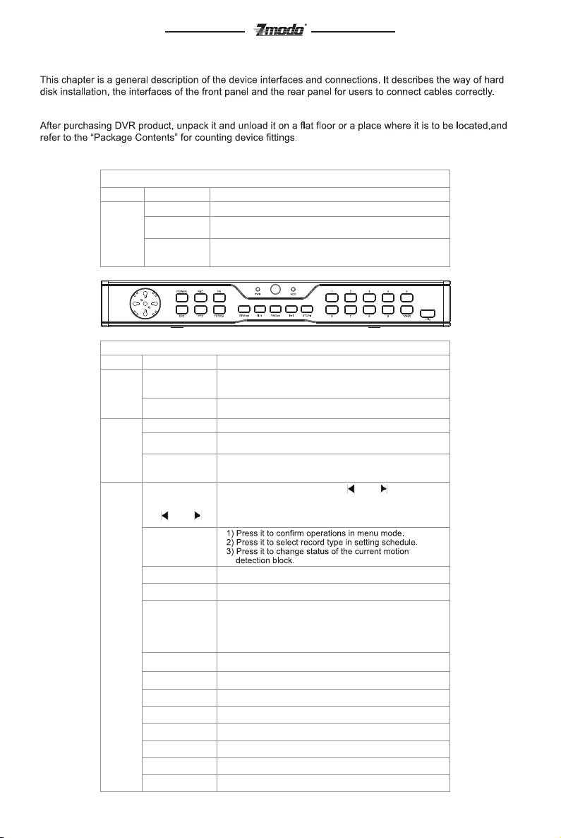
2 Front Panel Operation
Type Name Description
LED
TableII-1 4/8 channel DVR Front Panel Description
Power Red Power indicator. Red when switch on the power.
HDD
IR
Hard disk indicator. Red, or blinks when reading/writing.
Black when non-operation.
Remote Controller operation indicator. Green.
Blinks when operating.
Black when non-operation.
Type
Buttons
LED
Main
Functions
TableII-2 16 channel DVR Front Panel Description
Name description
Numbers:0-9
Numbers:10+/0
PWR
HDD
IR
Arrow Buttons:
【▲】,【▼】
【 】,【 】
OK
POWER
REC
FN
ESC
PTZ
TV/VGA
REW<<
PAUSE
FWD>>
STEP
STOP
1) Input numbers.
2) One key channel selection in preview mode.
3) One key channel selection in play mode.
Used in combination to choose more than 10 switch
channels in preview mode.
Red Power indicator. Red when switch on the power.
Hard disk indicator. Red, or blinks when reading/writing.
Black when non-operation.
Remote Controller operation indicator. Green.
Blinks when operating.
Black when non-operation.
1) When in menu mode, press【 】,【 】to move to
selection boxes, press【▲】,【▼】to select submenu
parameters.
2) User can switch ActiveX on screen.
Red PoPress it to power off device.
One key start/stop recording.
1) Press it to switch from single split to multi splits view
mode, or reverse in preview and playback mode.
2) Press it to enter/exit continuous selection when setting
motion detection area and schedule record.
3) Press it to set start time and end time in file search.
Return to upper menu. The same as 【ESC】 button
of remote controller.
One key PTZ control
User can switch TV/VGA in menu
play in slow mode/fast rewind
1.Play 2.Pause
fast forword
Go to next frame
Stop
5
Page 7
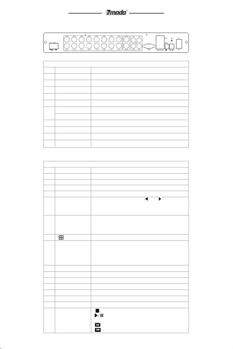
3 RearPanel of Operation
TableII 3 16 Channel DVR Rear Panel Description
NO.
Interface
1
Video In
2
TV Out
Audio Out
3
Audio In
4
VGA output
5
Network interface
6
USB interface
RS485
7
Alarm in
8
Alarm out
9
power DC 12V
10
4 Remote Controller
TableII 4 Remote Controller Description
NO.
Name
1
Rec
Power
2
3
Numbers
4
Function Buttons
Arrow Buttons
5
6
OK
7
8
FN
9
MENU One key system setup.
10
ESC Return to upper menu.
11
PTZ One key PTZ control
12
Backup Backup record
TV/VGA Switch the operation interface between TV and VGA.
13
CLEAR
14
SEQ call sequence,
15
Play Control Buttons
16
Discription
16 channels video input:BNC (1Vp-p,75Ω);
1 channel TV output,BNC(1Vp-p,75Ω);
1 channel audio output,BNC( 2Vp-p,600Ω);
4 channels audio input:RCA(2Vp-p,600Ω)
1 DIN-15
1 RJ45 10/100M self-adaptive
2 USB 2.0
1 Half duplex(+ -)
4 Channel switch-level input, N/O or N/C
1 Channel switch-level alarm output
Discription
Record
Press it to power off device.
Input numbers or select to switch among relevant channels.
DEL: Delete
1) When in menu mode, press【 】,【 】to move to
selection boxes, press【▲】,【▼】to select submenu
parameters.
2) User can switch ActiveX on screen.
1) Press it to confirm operations in menu mode.
2) Press it to select record type in setting schedule.
3) Press it to change status of the current motion
detection block.
Switch from single screen and multi-screen.
1) Press it to switch from single split to multi splits view
mode, or reverse in preview and playback mode.
2) Press it to enter/exit continuous selection when setting
motion detection area and schedule record.
3) Press it to set start time and end time in file search.
Alarm off.
: Stop
: 1) Play/Pause
2) One key file search.
:play in slow mode/fast rewind
: go to previous section
6
Page 8

5 Hard Disk Installation
The hard disk is not included in factory fittings. Users can mount suitable hard disk by calculating its capacity
referring to “Appendix 5.2 Methods of Calculating HDD Capacity”.
1) Installation procedure
*Open the DVR case. Mount the 4 shock absorption washers into the clamping slots (four protruding steps) in
the case.
*Connect the HDD data cable and HDD power cable to HDD.
*Attach the hard disk to the shock absorption washers by aiming installation holes to the case, hold and fix
them by 4 M3*12 Head Screws plus plain washers.
*Connect the HDD data cable and HDD power cable to the respond interfaces of main board.
*Replace the DVR top cover, and fix it by screws.
Note1: Please use the HDD special for DVR, and buy HDD from regular channels so that the quality can be
guaranteed.
Note2: Please format HDD for the first use, or system will sent error notification of “Hard disk error”
accompanied with audio alarm. Please see 4.9 Maintenance for details.
6 Rear Panel Connection
*Power Input
Connect power adapter to Power Input interface of DVR. Confirm that the DVR power supply input switch is
positioned correctly for the local voltage before connecting and powering on the unit.
Turn on the unit. The power LED will light if the power cable is connected correctly.
Note: Please use the power adapter contained in the package.
*Video Input
The video input interface is standard BNC socket, 1Vp-p, 75 Ω.
Note: The video signal cable should keep away from the interference of strong electromagnetism and city
electric field.
*Audio Input
The audio input interface is standard RCA socket, 2Vp-p, 600 Ω.
Note: The audio input resistance is a little bit high; please use active sound collection device or active
microphone. And the audio signal cable should keep away from the interference of strong electromagnetism
and electric field.
*Network Input
The network input interface is RJ45 10/100M self-adaptive.
Note:Confirm that the network band width is enough for transmitting high definition image smoothly.
*Alarm Input and Output
The alarm input device should be the type of GND connected alarm or voltage input alarm, which can be set
as N/O. or N/C.
The requirement of signal input level for voltage input alarm type is: low level: 0~2V; high level: 5~15V.
The green angle pins of signal cable are supplied for access of PTZ and alarming devices. Please follow
these steps to connect:
1、Pull out the angle pins that inserted in the alarm input and output interfaces.
2、Screw out the screws by micro Philips screwdriver, insert the signal cable into interface under spring, and
then tighten the screws.
3、Plug in the connected pins into green angle pin socket.
*PTZ Input
Connect the PTZ control interface to RS485 interfaces of rear panel. The connection method is similar as above.
Note: Please refer to PTZ manual for setting specific parameters, for some PTZ devices contain multiple
telecommunication protocols, baud rates and IDs.
*Video output:
*Video output interface: TV andVGA, which can work together simultaneously.
Note: VGA and TV cannot be in the operation interface simultaneously, but be switched by mouse, panel and
remote control in the menu.
VGA/Monitor Input
7
Page 9

Chapter Three: Menu Description
1 Menu Structure
FigIII 1Menu Structure
System
Setting
Manual Record
Record
Video
Net
Alarm
Maintenance
Save
Tool Bar
Record Search
PTZ
Clear Alarm
Quick Playback
Shut down
Single Channel
Four Channels
Nine Channels
Sixteen Channels
Position
Language
Video Standard
VGA Setting
Time Format
Time Setting
Password Setting
HDD Overwrite
Add User
Del User
Authority Manage
Preview Cruise
DVR ID Number
SPOT SETTING
Camera CH
PTZ Protocol
PTZ Baudrate
PTZ ID
Color Setting
Motion Detection
Mosaic
Motion Handling
Video Lost
Handling
Channel Name
Setting
Alarm Input CH
Alarm Input Type
Event Handling
Alarm Setting
Alarm Zoom Out
HDD Full Actions
Save & Exit
Exit
Restore Defaults
Logout
Video CH
Record Schedule
Record Quality
Record Frame Rate
Record Source
OSD Setting
Record Resolution
Sub Code
Network
IP Address
Subnet Mask
Gateway
Http Port
Command Port
Media Port
PPPoE Setting
PPPoE IP
DNS Address
DDNS
Auto Register
File Sharing
Email Setting
Mobile Port
Log View
Upgrade
HDD Manage
HDD Capacity
Hardware Version
Software Version
Software Release
Date
8
Page 10

2 Menu Operations
Press [SET] button to enter into system setting screen.
Press [●] button to start/stop recording manually.
Press [ ‖] button to play record file.
Press [PTZ] button to enter into PTZ control screen.
Note: This manual indicates the Menu selection icons and selection boxes in 〖XX〗; the buttons in Menu
screen (except menu selection icons) in<XX>; the buttons on front panel and remote controller in【XX】.
The highlight menu is the current active one. User can move highlight icon to the menu needed using
【▲】、【▼】、【 】、【 】button, and press 【OK】 button to confirm selection, or press 【ESC】
button to return to upper menu.
Selection box: User can move highlight icon to the selection box needed using 【 】、【 】 button, and press
【OK】 button to confirm selection. Multiple items are allowed to be selected together at once by left clicking
mouse.
Sub menu list: User can move highlight icon to the sub menu needed using 【 】、【 】 button. Or roll
mouse to select directly. Only one item can be selected here.
Edition box: when in edition box, user can type in numbers directly by pressing number buttons. Press 【DEL
】 to delete the character before cursor and press 【OK】 or 【ESC】 button to exit.
Sub screen button: Press it to pop up sub screen. When in sub screen, select〖Confirm〗to save
configuration and return to the upper menu. Press 【ESC】 or select〖Cancel〗to return to the upper menu
without being saved.
Use 【 】、【 】 to move highlight icon to any of the selection boxes. Press 【OK】 button to switch to
another selection status. Use【▲】、【▼】 to specify the sub menu value where sub menu selections exist.
Exit: User can click button on the right upper corner, or single right click mouse, or press 【ESC】 button to
enter into the Save & Exit screen. You can select exit directly or exit after being saved.
Note: There are two different ways to take effect: take effect instantly, take effect after being saved. Please
refer to the navigation for details.
Chapter Four: Operations
This chapter mainly describes the main system operations of DVR. Please see the following contents for
details.
1 Turn on
*Start-up
The Power LED will light after powering on correctly. Please refer to2.6 Rear Panel Connection for details of
connection method. Press 【Power on/off】 button to start up device. The preview screen will appear .After
pressing 【ESC】 button of panel or remoter, or right clicking mouse, the login box appears. Please select
proper user and type in relevant password to log in.
Note1: It costs about 60 seconds to start up, please wait for a moment.
Note2: Modify password by selecting <Tool Bar>→<System>→<System Setting>→<Password Setting>.
Set as indicated, new password will take effect instantly.
Note3: Default password for Admin is 111111.Default password for User is 111111;Admin password
can be restored to factory defaults by short-circuit “JP 1” on main board. After logining the DVR by Admin, the
Admin user can change user’s password. The system support 8 users, and the Admin is the manager user
with all permissions, whose name cannot be deleted or changed. The Admin user can add and delete all other
users and the permissions corresponding.
Note4: The DVR will buzz and “NO Hard disk” appears when without hard disk. User can choose whether
to buzz or not when without hard disk.
Note5: The DVR can identify display device automatically. When connected either to VGA or TV, the menu
will be on the specified screen automatically after start-up; when connecting VGA and TV simultaneously, two
images will be displayed on the screen , the menu will be on the VGA firstly. User can switch by clicking in
the tool bar.
*System settings
Language: Please enter<Tool Bar>→<System>→<System Setting>→<Language> to set language.
VGA Resolution: Please enter<Tool Bar>→<System>→<System Setting>→<VGA Resolution> to set VGA
resolution and refresh rate. It supports800×600@60Hz、1024×768@60Hz、1280×1024@60Hz、
1440×900@60Hz currently. Please select relevant values according to the parameters of VGA.
Date/Time: Please enter<Tool Bar>→<System>→<System Setting>→<Time Format> to set time format. 12
hours and 24 hours are supported. Please enter<Tool Bar>→<System>→<System Setting>→<Time Setting>
to set date and time.
Video Standard: Please enter<Tool Bar>→<System>→<System Setting>→<Video Standard> to set video
standard. PAL, SECAME, and NTSC are supported. Please setaccording to the parameters of camera.
9
Page 11

Note1: In order to avoid record files’ time confusion, you’d better stop recording before modifying system
time.
Note2: “Language” and“Time” will take effect instantly. “Record Resolution” and“Video Standard” will take
effect after being saved.
Note3: when the resolution setting exceeds the range of the display, please click 【ESC】->【2】->【
ESC】on the Front Panel or remote controller(within 3 seconds) to reduce the resolution to 800X600@60HZ
Note4: Users can refer to the navigations on the bottom of the main screen to look for relevant
guides.Meanwhile, navigation info will display“take effect instantly”/ “take effect after being saved”
2 Preview
After start-up system, the screen haslive view area and tool bar. Right click mouse in preview mode or press
【OK】on the front panel , the Tool Bar will appear. System status colum can be draged to anywhere on the
screen by mouse.it will be back to the original position after device restarting. The column can be hided by
right-clicking the mouse.
Videos, OSD of channel name, record time, and alarm notifications will be displayed on the screen.
1) Channel Status Display Area
Under preview mode, channel shows current input image and channel statues information ( video statues and
mode, motion detection)
*View Mode Switching
When in 1/4/6/8/9/16 splits view mode, the tile with high light green border is the current selected one. User
can use mouse or press 【Direction】 buttons to switch to another tile. If the audio output device is
connected, the audio can also be previewed together with video. The audio of current channel can be
previewed besides in playback mode.
User can select to display a single particular channel by pressing the Numbers buttons.
When in preview mode, user can enter into 1/4/6/8/9/16 splits view mode by pressing button directly, or
reverse.
Note: For 8 channel DVR, the view mode can be directly switched by tool bar. Please refer to 4.2.3“Tool
Bar”
*Image Parameters Setting
Please enter <Tool Bar>→<System>→<Video>→<Color Setting> to set brightness, contrast, hue and
saturation. It will take effect instantly.
Note1: User can set image parameters of one channel one time or all channels together at once by
selecting 〖All〗 in <Camera Channel>. It is similar in other screen when user wants to set four channels
together at once: select〖All〗 in <Channel>.
Note2: In preview mode, brightness, contrast can be adjusted by remote controller directly.
*OSD Settings
The OSD of channel name and system time is supported. Please senter<Tool Bar>→<System>→<Record
Setting>→<OSD Setting> to set. The channel name will be displayed on left upper corner and the channel
time will be displayed on the righter corner of the screen.
*Channel Status Display Area
The channel statuses include: “motion detection triggered recording” / “common recording” /”motion
recording”/ “alarm triggered recording” / “external alarm input” /“alarm output”.
Indication of “motion detection” / “common recording” / “alarm recording” will be displayed on the right upper
corner of screen. The details are as follows:
indicates “motion detection”. The settings of motion detection include sensitivity and area selection.
Please see Motion Detection Settings for details.
Blue indicates “common recording”.Please see Record for details.
Green indicates“motion detection triggered recording”.
Red indicates “alarm triggered recording”.
Grey indicates “manual recording”.
Indication of “external alarm input” / “alarm output” will be displayed on system status column or Tool Bar. The
details are as follows:
The 4/8 icons indicate the alarm input status. If alarm defence mode is set, the icon is , otherwise it
is .When alarming, it changes into red . External alarm input can trigger multiple events handling,
please see Alarm Settings for details.
: The icons indicates alarm output. When alarming outputsoccuring,it changes into red .
1) system status bar
In preview mode, the system status bar will display current system status, including: "External alarm input" /
10
Page 12

"Alarm output" / "hard disk capacity" / "number of the client connection" / "system time."
Indicateshard diskbeing ok.The number indicatesthe percentage of the total capacity of the hard disk.
Indicates“Hard disk error” Or “No hard disk”.
Indicatesclient connection. The number shows client linking number
Indicates“No client connection”
2) Tool Bar
Right click mouse or press [OK] button in preview mode, the Tool Bar shown as below will appear:
FigIV 1 System toobar
: Hide the tool bar.
: System configuration. Please see IV.2 Menu Structure for details.
: Manual record. Please see IV.3.1 Manual record for details.
: Search, playback and backup record files, please see IV.6 Video Playback and IV.7 Videl Backup for
details.
: PTZ operation. Please see IV.5 PTZ Control for details.
: Click to cancel alarm notification. Click this button will pop a message to show the present alarm
information.
: Fast playback.User can enter 10, 20, 30, or 60 seconds before position to start playback and can also
jump to a specified time in the video.
: Power off.Click this button will pop a message of“confirm password”. User has to enter Admin
password to shut down.
、 、 :To set the preview mode of “Single splits view” ,”4 splits view”,”6 splits view” “8
、、、 、 、
splits view” “9splits view” “16 splits view”.
:Fast switch TV and VGA. Menu will not be available on the current screen, only a preview image.
:To adjust the screen, 8 pixels per unit.
:To reduce or increase screen in vertical direction.
、 : To reduce or increase screen in horizontal direction.
、 、 、 : To move the screen up, down, left, right.
: To zoom out the screen to largest and show in central.
Note1:When mouse moves to the tool bar icon, the indication information will come out to help users to
understand.
Note2:When video source is PAL, screen display range max is 720*576;When NTSC, screen display
max 720*480.
Note3: Switch display menu between VGA and TV by selecting【ESC】->【1】->【ESC】(sequence
must be pressed within 3 seconds) on the remote control or Front panel.
3 Record
Record type contains manual record and schedule record. The priority of manual record is higher than
schedule. If the record schedule is conflict with manual record, the manual record will be processed firstly
until the manual record being canceled.
Record types include “common recording” / “alarm triggered recording” / “motion detection triggered
recording” / “alarm | motion detection triggered recording”. Each of them is indicated with grid of different
color, and each color indicates a particular record status. Please see Fig IV-2record schedule for details.
Record resolution: The device support "CIF" / "HALF D1" / "D1"format.
Record quality: “Best 768Kbps” / “High 640Kbps” / “Better 512Kbps” / “Common 384Kbps”. And “User setting”
can help user to set one bit rate up to 2048Kbps.
Record frame rate: if the current selection is PAL, the frame rate options are “All” / “12” / “6” / “3” / “1” /
“Customized”. If the current selection is NTSC, the frame rate options are “All”/ “15” / “7” / “3” / “1”
/“Customized”. Default is “All”, 25 fps for PAL and 30 fps for NTSC.
Record Resource: “Video” for video only or “Video and Audio” for recording video and audio.
11
Page 13

Note:Please refer to Appendix 6.2 for the methods of calculating HDD capacity.
1) Manual Record
Please enter <Tool Bar>→<Manual Record> to let the specific channel record or not.
Press【●】 button to start/stop recording manually.
Note1:The type of the video recorded manually is “common recording”.
Note2: The highest priority of record mode is manual record.
2) Record Schedule
Please enter<Tool Bar>→<System>→<Record Setting> to set record schedule. The setting screen is shown
as the figure below:
FigIV 2Record Schedule
1
2
3
① The current recording channel number
② The record schedule
③ Description of record type
Users are free to select a week day or the day of a period of time System provides a recording option for
hours every day ora week day. Unit is hour. One grid indicates one hour.
① Move highlight icon to a time grid using 【Direction】 buttons.
② Specify the recording type by repeat pressing 【OK】 buttonor double left clicking mouse,(the color of the
grid will change relevantly).
③ Select【OK】to confirm settings. The settings will take effect after being saved.
Note1: User can copy the current setting onto the neighboring grid by pressing 【Fn】button first ,
【Direction】 buttons secondly, and then the 【Fn】 button again to exit. Or user can drag mouse to set.
Note2: When motion detection recording is selected, the motion detection sensitivity and area should be
set ahead. Please refer to 4.4.2 Motion Detection Settings for details. When alarm recording is selected, the
alarm triggering settings should be set ahead. Please refer to 4.7.2 Event Handling for details.
4 Camera Control
1) PTZ Control
*PTZ Settings
Enter <Tool Bar>→<System>→<Video> to set camera channel, protocol, baud rate and ID.
Note: The different PTZ controlled by one PCI should have corresponding PTZ ID. There are 256PTZ ID
supported currently: 0-255.
*PTZ Operations
In preview mode, select a tile first (in 4/9/16 splits view mode, the selected tile is with highlight greenborder)
using mouse or 【Numbers】 buttons, and then enter <Tool Bar>→<PTZ Control> to the PTZ Control screen
that described as the table below:
2
1
6
8
9
10
7
4
5
3
12
Page 14

NO.
Name Discription
Direction
①
Speed
②
Advanced
③
Focus
④
Iris
⑤
Auxiliary
⑥
Zoom Click to zoom in/zoom out (it is disabled for cameras with automatic focus).
⑦
Preset
⑧
Sequence
⑨
Track
⑩
Table IV 1 PTZ Operation Description
Click the arrow icons to control direction of PTZ.
Click the center icon to call sequence or run scanning.
Please refer to the PTZ manual for details of PTZ scanning mode.
Set the turning speed of PTZ camera.
Click and to show/hide the advanced setting screen
(the part under the blue bar ).
Click to focus-in and focus-out (it is disabled for cameras with
automatic focus).
Click to make the image brighter or darker (it is disabled
for cameras with automatic iris adjustment).
Open/close auxiliaries.
Click to open and click to close. Different functions
respond to different protocols. The auxiliaries include light,
rain brash, and power etc. please refer to PTZ manual for details.
NOTE: Up to 2 auxiliaries are supported on device side.
Up to 4 auxiliaries are supported on client web side.
1, Select the preset number in the preset window.
2, Position the camera as desired position. Save the position by clicking .
Repeat the step 1and 2 to reset the desired position.
Call preset: Select the preset number you want to call, and click on the go
to button . Clear/reset preset: Select the preset number you want to
clear/reset and click on the clear button .
Sequence is a running route of camera that passes through multiple
presets. Set sequence:
1. Select preset number you want to call. Click on set button .
2. Repeat step 1 and 2 to add the other presets till finishing.
Click button to end setting. Click on button to clear sequence.
Track is a continuous running route of camera.
Set track:
1. Click on to start setting.
2. Move camera as the track and pattern you want it to run.
3. Click on again to finish setting.Click on to run track and click
again to stop running.
Note: Whether Track is supported or not is depending on the type of PTZ.
Note: IE side supports 5 auxiliaries setting. Local side supports 3 auxiliaries.
2) Motion Detection Settings
Motion detection settings include sensitivity and area. The sensitivity includes three levels: High, Mid, and
Low. Please select <Tool Bar>→<System>→<Video>→<Motion Detection> to set.
Mouse Operation: Drag mouse on screen to create grid.
Panel Operation: There are totally 16 X 12 blocks in screen. Move highlight icon among the blocks by using
[ ]、[ ]buttons. Please follow these steps below to set:
1.Move highlight icon to one of the blocks you want to create by using [ ]、[ ] buttons. Press [OK] button
to confirm. The created block will be in highlight blue.
2.Press [Fn] button to copy the current configuration, and press [Direction] button to copy to the relevant
grid. Press [Fn] button again to exit copying.
3.Repeat steps 1 and 2 to set the second area.
Press [ESC]to exit setting.
In the Motion Detection Settings, users are free to select a certain day of the week or a period of time within a
future day(Smallest unit is one hour. One block indicates one hour). System provides a recording option for
hours every day or a week day.
3) Mask Setting
Mask setting function can make some regions of the image invisible. These regions in preview image and
playback image areall filled with black pixels. The method to set maskis similar with motion detection setting.
You can right click mouse in the area where mask have set to cancel this function. You can stop setting when
you right click mouse in one area where havenomask setting. There are four regions can be set in one
channel.
5 Playback
*File Search
13
Page 15

Specify the date/time and channel number by selecting <Tool Bar>→<Record Search>. Click〖Search〗 in
the pop-up screen to start searching. The searching results will be list on the screen in responding different
colors so as to distinguish different record types. Please see Fig IV-2Record Schedule for details of colors
description.
FigIV 3File Search
User can click mouse or use panel to specify time.
Panel operation: move highlight icon to relevant selection box using [ ],[ ] buttons.
Move highlight icon to date/time selection box, modify time using [▲],[▼] buttons.
Move highlight icon to channel selection box, press [OK] button to select it or cancel selection.
Move highlight icon to , press [OK] button to zoom in/zoom out timeline (time ruler). If the timeline is out
ofscreen, please move highlight icon to and press [OK] button to display the part out of screen in order.
After setting time, channel number and timeline, move highlight icon to [Search] using [ ],[ ] buttons, and
press [OK] button to start searching.
After searching over, press [Fn] button to pop-up the timeline for selecting start point. Press [ ],[ ] buttons to
move timeline, press [Fn] to confirm selection. Press [Fn] again to pop-up the second timeline for selecting
stop point,press [ ], [ ] buttons to move timeline, press [Fn] to confirm selection.
After all settings, move highlight icon to [Play] using [ ],[ ] buttons, and press [OK] button to start playing.
move highlight icon to [Backup] using [ ],[ ] buttons, and press [OK] button to backup.
*Playback Control
:Fast backwards, the availablefast backwards speeds are: 8X and 16X.
:Pause the current play, or stop the current pause.
:Stop playing.
:Click to control speed of Forward, the available forward speeds are 1X, 2X,4X,8x 16x, 1/2X and 1/4X.
:Go to next frame.
:Click to switch from single split view mode to 4/9 splits view mode, or reverse.
The status of playing will be displayed on the right upper corner of screen:
Indication
Speed
16X
16X fast
forward
8X
8X fast
forward
1X
Normal
playing
1/2X
1/2X
forward
1/4X
1/4X
forward
8X
8X fast
backwards
16X
16X fast
backwards
Note: On the playback screen, the image will display in full-screen.
6 Backup
Enter<Tool Bar>→<Playback> to search, backup and playback the specific record files you needs.
Click【Backup】to enter into the backup screen. System will detect all the backup devices available and
display them. Please select the suitable device and record type according to requirement first, and click
【Backup】 to start storing.
Note: The record types include H.264 Raw , MP4 and AVI . When backup in MP4 types, the special player
plug will also be backed up into USB together automatically. After player plug is installed, the stored video
files can be played by Windows Media Player.
14
Page 16

7 Alarm Settings
Please make sure that the alarm input and output cables are connected correctly. Please refer to II.6 Rear
Panel Connection for details.
Select<Tool Bar>→<System>→<Alarm Setting> to configure alarm parameters in the pop-up screen.
Note: All the settings will take effect after being saved
1) Alarm Input
The alarm input attribution includes N/O. and N/C. Please select a suitable attribution according to the types
of alarm device connected and control modes of alarm device adopted.
N/O.: Normally open. Circuit connected when alarm single triggered.
N/C.: Normally connected. Open when alarm single triggered.
2) Alarm linkage
The alarm triggered event handling include: record/alarm output/PTZ/sound output/alarm zoom
out/E-mail/report to center/FPT upload file. The channel alarm input can zoom display interval 1-10s optional.
If the display interval time is set to off, the zoom display will be invalid.
After using the “zoom out image” ,Alarm zoom out, report to center, IE client preview will zoom out
simultaneously.
Note1: if user wants to set alarm triggered record, please set the record schedule first at “Record
Schedule”.
Note2: if user wants to set alarm triggered PTZ, please select the channel number first, and then to set
(only preset 1 can be selected).
Note3::After alarm, email will be sent immediately with the attachment of the caught snapshot.
Note4: Once FTP server is set, FTP will upload file after the alarm. FTP server will receive the caught
snapshot.
3) Alarm Defence and Schechle
User can enable customized schedule in advanced menu, which is similar with the schechle of record .In the
alarm defence status, the icon of alarm input will appear as yellow.
4) DEVICE EXCEPTION ACTION
Select < DEVICE EXCEPTION ACTION >→Enter Device exception handle screen. Choose among these
three options: HDD full, network disconnect, and IP conflict. For the hard full setting, user can select “alarm
output”/ “sound”/ “report to center”/ “email”. Network disconnect and IP conflict can only be set to “alarm
output”/ “sound”. After this setting has been saved, device exception will be handled the way user has
selected.
8 Network operation
1) Network settings
Please enter<Tool Bar>→<System>→<Network Setting>→<Network Connection>, there are three
connection types: Static IP, DHCP and PPPoE.
*Static IP:If this type selected, please type in IP address, subnet mask, and gateway. User can ping network
to check its connection status.
*DHCP:If this type selected, a DHCP server should be set in network. A dynamic IP of device will be
assigned automatically and displayed on IP Address column.
*PPPoE:Click 【>>】, the PPPoE setup screen will appear. Type in user name and password and click
【OK】 to confirm. System will dial automatically. After accomplishing dialing, the IP address will be assigned
and displayed automatically on IP Address column. User can save the user name and passwordeven if the
dialing is not successed.
The following are types of ports:
*HTTP Port:It is the port number of browsing through IE. Default is 80.
*Signal Port:It is the first entry port for communication between web client and device, which is mainly used
for controlling of log-in, log-out, real-time preview, remote playback, and remote download, etc.
*Media Port:It is for media stream transmitting including real-time stream, voice stream and file stream etc.
*DDNS:Click 【>>】, the DDNS setup screen will appear. Slect a DDNS server and type in the DDNS
address,user name and password.
Auto Registration: SlectactivatingAuto Register and click【>>】,the register setup screen will appear. Type in
the register server IP,port and register interval time.
*File sharing: After activating file sharing function, the PC is able to access video files in DVR HDD via
network neighborhood
15
Page 17

*sharing file access methods:Open Network neighborhood, type in\\IP address, for example:
\\192.168.10.220, enter the login interface, type in the Super Admin user name and password, the shared
files can be accessible now(Open folder “videoout”.)
Note:After player plug is installed, video files can be played by Windows Media Player.
*Email Setting:Click [>>], the EMAIL setup screen will appear. This function requires to take effect of the
alarm linkage. Enter the mail server address in the screen (support domain method), login account,
password, recipient, sender mail address. Pressing the [Test] button next to sender mail address will send a
test email.
*Mobile port: port is the channel of mobile phone when the data transmission, all the media and signaling
data transmitted by this port.
*FTP server: select FTP upload, and click [>>] to set FTP server IP, user name and password. The caught
snapshot can be uploaded to the FTP server.
*UPNP: start UPNP, select [>>], device will automatically find the intranet modem UPNP service, and map the
HTTP, signal, media, cellphone port, and return the map result and modem’s internet IP. After mapping is
successful, user can access the IE client from an internet enabled PC through the internet IP.
*IP ACCESS: When turned off, any PC can access the device; When black list is in use, a PC with an IP
entered in the black list cannot access the device’s IE client, but PC not on the list can access it; When white
list is in use, a PC with an IP entered on the white list can access the device’s IE client, but other PCs cannot
access it.
*Time synchronization: Click [>>] to start synchronization, the device can automatically synchronize by setting
the server name, synchronization interval, time zone.
Note1: All of these settings of network will take effect after being saved.
Note2: Currently only support PPPoE mail server with SMTP protocol.
Note3:Enter into mobile phone system and type in IP address into IE address column in the form of
http://xxx.xxx.xxx.xxx/download.html.
Versions supported by client side are as follows: Android 2.1~2.3; Symbian V3/V5,windows mobile5.5/6.1,
ipad ios 5 and Iphone,BlackBerry 7. Please refer to “Appendix5:Introduction of Mobile phone Monitor” for
theDetails.
2) Web Client Operation
Open IE browser, type in IP address, the log-in screen will appear.
Note1: If PPPoE or DHCP is selected, user has to check IP address again after restarting device.
Note2: If it is the first time login through IE, please install the Active X of IE and type in user name and
password. Default user name and password are: Admin (case sensitive). If the plug-inscan not be
downloaded normally, please lower IE's security level:
Click [Tools] and choose [Internet Options] in the IE menu bar to enter the ‘Internet Options’ page. Choose
[Security] and click [Custom level…] to enter the ‘Security Settings’ page, Enable ActiveX controls and
plug-ins,Click [OK] to save the se ttings.
Note3: Compared with the local side, the added settings on IE Web client side are as the table below:
Menu Contents
<Server>Tab Name of server is configurable on Web client side.
<Channel>Tab The channel OSD is User-defined.
<Device>Tab User can adjust miniNVR time accordance with PC time.
<State>Tab Device states can be viewed directly.
Table IV 1 Settings added on IE side
3) Web Screen Description
FigIV 3Web Screen
16
Page 18

*Address
Display the DVR IP address.
*Tool Bar
The description of icons from left to right is:
Configure device parameters.
Search and playback record files.
View logs and export them.
Set the storage directory of record files.
Click to switch image view modes among full-screen, single split view mode and 4/8/9 splits view mode.
Log-out, restart device, Clear alarm
*Alarm Notification
When network connection is broken or abnormal, the alarm notification of “No heartbeat of device, please
check the network!” will be displayed in the right up side of the main screen. After recovery of network, the
preview will be displayedautomatically.
When alarms ofremote notification occur, the alarm notification with alarm input number contained such as
“Device alarm: IO alarm, IO input x” will be displayed in the right up side of the main screen.
When alarms of motion detection with remote notification occur, the alarm notification with the alarm channel
number contained such as “Device alarm: motion detection, channel 1” will be displayed in the right up side of
the main screen.
When alarms of video loss with uploading to center occur, the alarm notification with the alarm channel
number contained such as “Device alarm: video loss, channel x” will be displayed in the right up side of the
main screen.
*Preview
, :Adjust image contrast up/down.
, :Adjust brightness up/down.
:Start/stop voice monitoring. The icon will turn to green whensound monitoring.
:Start/stop recording. The icon will turn to green when recording.
:Click to snapshot.
:Stop preview.
Note: Click to set the storage directory of record files and pictures captured.
*PTZ Setting
The PTZ setting of client web is similar as the PTZ operation of local device, please refer to IV.5.1 PTZ
Control.
Note: IE side supports 3 auxiliaries setting.
4) Device Parameters Settings
Click , the parameters configuration screen will appear. All of the configurations are divided into the
following six selections:
*Server
It includes the configuration of server, network, and version information. All of these configurations can be set
in [Tool Bar]→[System].
Note: If the DHCP mode selected, the IP address is assigned automatically without being modified.
*Channel
User can set motion detection, video loss, OSD, image bit rate and frame rate, image parameters and record
schedule here.
Note: User is allowed to set single channel first, and then to copy the settings to the other channels.
*Serial
User can set PTZ protocol, baud rate, and address code here. All of these settings can be done by selecting
from [Tool Bar]→[System]→[VideoSetting].
*Alarm
User can set IO alarm and event handling here. All of these settings can be done by selecting from [Tool
Bar]→[System]→[Alarm Setting].
*User Management
Including user authority and password setting. Relevant interface information should be <Tool Bar>→
<System>→<System Setting>→【Advanced Setting>>】
17
Page 19

“User” authority and password can be changed by “Admin”,
*Device
Upgrade:Click [Browse] to select the software package needed, and click [Start Upgrade] to progress. User
can stop the progress of upgrade by clicking [Stop Upgrade].
Adjust Time:Click [Adjust Time] to adjust time of device accordance with the PC time.
*State
The information of HDD and channel state is contained here.
5) Playback
Click , the playback screen will appear.It includes file search, playback and download.
*File Search
The file search part is on the right upper side of the screen, please set target, type, start time and end time
there. Then click [Query] to start searching. The result will list on the table. Specify the files in the table list
and click on the playing control button or download button to do the relevant operations.
Query
Target: Localhost
Kind:
All Record
Beigin:
2009-07-10 00:00:00
End:
2009-07-10 09:21:09
Channel: 1
Query
*File Playback
The play control screen is on the left side of the screen. It includes image display area, play control bar, and
channel information.
Click [Play], the record files selected will be displayed in time order. The progress of playing is shown as the
figure below:
The playing control bar is shown as the figure below. The descriptions of all these icons from left to right are
as follows:
Play; Pause; Stop; Go to next frame;
Fast play option (The speed of playing will be doubled by each clicking. It includes: 2X, 4X, 8X, and 16X);
Slow play option (The speed of playing will be half down by each clicking. It includes 1/2X, 1/4X, 1/8X,
and 1/16X);
Enhance contrast; Reduce contrast;
Enhance brightness; Reduce brightness;
Open/close voice; Go to previous file;
Go to next file ( and is enabled only when multiple record files being selected to play);
Snapshot (the storage directory can be set on the pop-up screen by clicking ).
The information of the record file selected will be displayed in the area shown as the figure below. It includes
device’s IP address, current play speed, channel number and start/end time of the record file.
Target: 172.1.10.220 Play Speed: normal
Channel: 1
Time:
*File Download
The File download operation part is on the right bottom of the screen.
Click to set the storage directory of the file selected. Click [Download] to start downloading.
6) Bidirectional Talk
Click in the Tool Bar to enable the bidirectional talk between Client Web and DVS side. A microphone
should be connected to the device through the Line-in interface. Click again to stop talking.
7) Log
Click , the screen of device logs will appear. There are four options for choosing: All, according to time,
according to type, according to time and type.
To search logs, please select the search mode and channel number needed first and then click [Search] to
progress.
Click [Export] to export logs in html format.
18
Page 20

8) Remote Upgrade
Select <Server>-<Manage>, click [Browse] to specify the file for upgrade, and click [Start] to upgrade. User
can click [Stop] to stop upgrading in progress.
9 Maintenance
Please enter<Tool Bar>→<System>→<Maintenance>or <Save> to enter screen of maintenance.
1) Log view
1 Select the type of log to be searched: All/ Operation/ Exception/ Alarm/Front-end device.
2 Select the time scope to be searched.
3 Click [Search] to display the detail information of log.
Note1: If the logs searched contains alarm event log, user can directly play the video recorded during the
alarm event happens by clicking【 on the right side of screen.
Note2:The maximum number of logs supported currently is 10000. The storage mode adopts overwrite
mode: continuously overwrite the oldest data when the database is full.
2) Upgraede
The upgrade modes supported now are USB/ IE/ Remote Software:
USB:Please make sure the USB device is connected correctly and the upgrade applications have already
being copied into USB root directory. Please follow the prompts to operate.
After accomplishing upgrade, the Restart prompt screen will appear. Please restart the device, the latest
software will be installed automatically then.
IE:Please refer to5.2.2 Device Parameters Settings for details.
Remote Software:Please follow the user’s manual of remote software to operate.
3)Device Information
HDD Size: display the current total capacity of HDD and the remaining capacity
Hardware Version: display the version of hardware.
Software version: display the version of software.
Release date: for the current software.
4) Format HDD
Please make sure that all of the important record files have already being saved before formatting HDD.
Please stop all of the recordings in the beginning of formatting HDD. And follow the prompts to operate.
5) Lock out
Please enter<Tool Bar>→<System>→<Save Setting>→<Log Out>, the preview screen will appear together
with the log-in box. Please type in the password for other operation.
6) Restore to factory defaults
Please Enter <Tool Bar>→<System>→<Save Setting>→<Restore Defaults>, system will remind you of
whether recovering or not. Click〖Confirm〗 to process restoring.
Note1: Please refer to Appendix VI for the default values.
Note2:The system language, time, camera P/N system, and network settings (IP address, subnet mask,
gateway, HTTP port ) will not be recovered by restoring to factory defaults.
7) Input/output parameter
Please enter<tool bar>-<system>-<maintenance>, when USB is connected, the device setting parameters
can be exported to the USB device.
Parameters can import to the device from USB. Reboot the device, and the imported parameters will take
effect.
Note: parameters importing between same mode devices, otherwise it would bring abnormal.
8) Auto-maintenance
Please enter<tool bar>-<system>-<maintenance>. Maintenance will not reboot automatically if
auto-maintenance is off. There are three types of maintenance: per day, per week, per time.
】
10 Advanced Settings
Note: Operation of this chapter needs permission referring to the current user's authority ,please using
Admin to log in.
1) Settings of System
Please enter<Tool Bar>→< Setting >→<System>→【Advanced Setting>>】
Select <PREVIEW CRUISE>→【>>】o enter the setting screen. Set the preview cruise interval, 1/4/9 cruise
way. It will take effect after saving the settings, the screen will be cruised in accordance with the setting
19
Page 21

intervals over the segmentation preview. Set < PREVIEW CRUISE> is not enabled, the preview will be back
to the initial interface after saving the setting.Select <DVR IDNUMBER>,the number can be entered : 1 ~
99.The remote controller and 485 keyboard can control device one to one when setting the same number .
select <SPOT SETTING >→【>>】to enter the setting screen. Set SPOT channel and time: the DWELL time
decides a period of channel which be slected.
Click【Add】to add the channel to the Matrix output. After being saved, the video output will take effect. All of
video channels connected with video inputs of DVR can be sequentially switched for SPOT monitoring output.
Select<DST>-【>>】to enter DST settings. User can set beginning and ending dates and time of DST.
Device will automatically adjust the time after being saved.
After started <menu timeout>, when there is no any mouse motion on the menu timeouts settings screen for a
while, preview screen and search screen, control device will automatically lock the screen. User need to
re-login to unlock the screen; PTZ, video playback and back-up screen are never be locked.
Select <channel lock>-【>>】to enter channel lock setting screen. Click the channel as wanted, and select
【OK】. User can not see the locked channel after login out. Only Admin can set and unlock channel lock
settings.
Note: <system setup>-<advanced settings>, user can set recourse distribution mode, code mode and
playback mode.
2) User management
Please enter<tool bar>-<setting>-<system setup>-<advanced setting>. Select <ADD USER>→【>>】to enter
the settingscreen, the password of new user is 111111, user can enter < Tool Bar>→< Setting >→<System>→
<Password Settings>to modify the password; Select <DEL USER>→【>>】to enter the settingscreen, Admin
can delete the specified user.
Select < AUTHORITY MANAGE >→【>>】to enter the settingscreen.select < AUTHORITY MANAGE >→
【>>】to enter the settingscreen.
Authority setting contains the authority optionsof local and remote.
Select < AUTHORITY MANAGE >→【>>】to enter the setting screen. select < AUTHORITY MANAGE >→
【>>】to enter the settingscreen.
Authority setting contains the authority optionsof local and remote.
Fig IV 4AuthoritySetting
Move highlight icon to anoption using 【Direction】 buttons. Press 【OK】 button or click mouse to select the
option.
3) Advanced Setting of Record
Please enter <Tool Bar>→< Setting >→<Record>→【Advanced Setting>>】→<SUB STREAM>,select
Enable, press 【>>】 key to enter the setting screen.Then user can customize the sub-stream frame rate and
bit rate. Sub-stream support frame rate 1-15, bit rate 32K-512K.
4) Advanced Setting of Video
Please enter <Tool Bar>ering/ " BuzzeVideo>d [Advanced Setting>>],
*MOTION HANDLING
After the setting area moveingmotion,theincident could be linked to those handling : “RECORD " / " ALARM
OUT " / " Buzzer " / " UPLOAD "
Note:Please refer to “4.2.2 Motion Detection Settings” for the setting of detection area and sensitivity.
20
Page 22

*VIDEO LOST HANDLING
After the slected video channel being lost, the incident could be linked to those handling : " ALARM OUT " / "
Buzzer " / " UPLOAD "
*CHANNEL NAME SETTING
After the slected video channel being lost, the incident could be linked to those handling : " ALARM OUT " / "
Buzzer " / " UPLOAD " User can input the channel name through the soft keyboard. It only support letters,
select the 【OK】to confirm the settings.
Chapter Five: Appendix
1 Specifications
System
I/O Interface
Video
Audio
Environmental
DVR Type 16 channel DVR Specifications
Video Input
Audio Input
VGA Output
CVBS Output
Audio Output
USB Interface
RS485
Network Interface
Alarm Input
Alarm Output
SATA Interface
Video Compression
Video Standards
Video Compression
Resolution
Frame Rate
Video Output Bit Rate
Preview Resolution
Playback Resolution
Audio Compression
Input/Output
Sampling Rate
Audio Channel Type
Sampling Bit
Power Supply
Operating
Temperature
Operating Humidity
Power Consumption
Dimension
Table V 1 Specifications
Linux 2.6 O/S
Pentaplex operation: record, playback, preview and network
browse, backup supported.
16 channel, BNC, 1Vp-p,75Ω
PAL (625 line, 50 f/s), NTSC (525 line, 60 f/s), SECAM
(625 line, 50 f/s)
4 channel, RCA, 2Vp-p,600Ω
1 channel, DIN-15(optional); 800×600@60Hz、
1024×768@60Hz、1280×1024@60Hz、1440×900@60Hz
1 channel, BNC, 1Vp-p,75Ω
1 channel, RCA, 2Vp-p, 600Ω
Support USB storage device, USB mouse, USB burner.
1 port, receiving and transmitting duplex supported.
4RJ45 10/100M self-adaptive.
4 channel NO/NC.
1 channel NO/NC, relay: 30VDC/1A,125VAC/1A
2 SATA port, 2 SATA HDD up to 2T supported.
Video & Audio
Video & Audio
H.264 Baseline
PAL/NTSC/SECAM
PAL:352×288(CIF)NTSC: 352×240(CIF)
PAL:25F/S/CH 1,3,6,12,25 and user-defined optional;
NTSC: 30F/S/CH 1,3,7,15,30 and user-defined optional.
32kbps-2048kbps(14M byte/hour - 922M byte/hour).
PAL:720×576(D1),horizontal line 550, vertical line 450
NTSC:720×480(D1),horizontal line 550, vertical line 400
PAL: 352×288(CIF),horizontal line 300, vertical line 250
NTSC: 352×240(CIF),horizontal line 300, vertical line 220
G.726 ADPCM
8KHz
Mono
16 bit
DC 12V 5A,positive inside, negative outside,
power adapter is connected outside.
0℃-+50℃
10%~90%RH
<12W(without HDD)
13.9in (W) x 10.8in (D) x 1.85in (H) / 354mm (W)
x 275mm (D) x 47mm (H)
21
Page 23

Table V 2 Main Functions
Main Functions
Operating
Interface
Record
Playback
Backup
Network
Mobile phone
monitoring
Log
Operation
PTZ Control
Alarm
Management
Account
Management
Auxiliary
Function
Multiple control methods: mouse, IR remote controller, front panel and GUI with
navigation supported.
Recording status and alarming status can be displayed directly on
desktop and front panel.
Five recording modes: Manual, Schedule, Motion Detection, Alarm, and Motion
Detection & Alarm supported.
Selectable Record Quality: Best, High, Mid, Low and User-defined.
Play progress bar supported.
Multiple channel video/audio playback simultaneously.
Play, pause, stop, single frame forward, fast forward and backward
(up to 4/9ruple when playback 4 channels) supported.
Multiple backup modes: USB flash disk, USB HDD, USB CD-RW, and DVD-RW
supported. The output format can be H.264 RAW..
IPv4, PPPOE client, DHCP client and TCP/UDP protocol supported.
The Web Client and Client Application Software are provided for remote configuration,
video browse, local recording, local and remote playback, and remote PTZ control.
Network transmitting supports independent coding.
The time delay of LAN is less than 300ms.
Versions supported by client side are as follows: Android 2.1~2.3; Symbian V3/V5,
windows mobile5.5/6.1,ipad ios 5 and Iphone,BlackBerry 7
The log of operation and alarming will be saved automatically. User can directly play
the record files that being record when the alarm event occurs.
Multiple protocols: Pelco-P, Pelco-D, and Samsung, etc. supported. Upgrade of
protocol supported.
Multiple PTZ operations: Pan, Tilt, Zoom, Preset, Sequence, Track and Auxiliary
Switch supported.
4 channel alarm input NO/NC supported.
Motion detection and alarm of video loss supported.
Trigger recording, Linkage PTZ preset and Bee alarm supported.
The alarm information can be sent to Web Client or Client Application Software
through network.
Multi- account supported. Users can set & recover password,
authentication management.
Hardware Watch Dog supported. Device will be restarted if operations being
not respondedfor 30 seconds or more .
2 Methods of Calculating HDD Capacity
1) Calculate the maximum capacity of the build-in hard disk.
*Timing Recording:
Step 1: Calculate the maximum capacity of the hard disk needed in selected channel per hour, suppose as Si
(MByte) (i is the channel number), and suppose the bit rate of the channel selected as D (Kbit/s). The formula
of calculation is:
Si =(D*3600)/(8*1024)= D * 0.439453125 MB
Step 2: Confirm the storage time length, suppose as T hours. The total maximum capacity of the hard disk
needed in selected channel for T hours, suppose as St is:
St = T * S1
Step 3: Confirm the total numbers of the channels, suppose as n. The total maximum capacity of the hard
disk needed, suppose as Sc is:
Sc = S1 + S2 + … + Sn
Alarm Recording:
Suppose the rate of alarming as α%. The capacity of the hard disk needed in alarm recording supposed as
Sa is:
Sa = Sc * α%
2) Calculate the compression bit rate for recording T hours.
*Timing Recording
Step 1: Suppose the capacity of the hard disk as S, the total numbers of the channel as n. The capacity of
hard disk needed per channel supposed as Di is:
Di = S / n
Step 2: Suppose the total recording time as T hours. The capacity of the hard disk needed per hour per
channel supposed as Dt is:
Dt = Di / T
Step 3: The bit rate of all channels supposed as Dc is:
22
Page 24

Dc = Dt *(8*1024)/ 3600 = Dt * 2.2756 (Kbit/s)
3) Default Values
Menu Options in menu Default
LANGUAGE
Video Standard
VGA Setting
Time Format 12 hours,24 hours Time Format
Time Setting Click into sub menu screen year-month-dayhour:minute PM
DST Off, on, click into sub menu screen Off
Password setting Click into sub menu screen.
System
HDD Overwrite
Settings
Add user
Delete user
Authority manage Click into sub menu screen Admin
Preview Cruise
Device ID number
Menu time-out setting
Channel lock setting
Rescourse distribution
mode
Record Schedule Click into sub menu screen
Video quality Best, High, Mid,Low
Record Frame Rate
Record Resource
OSD Setting
Record Resolution
Sub-code
PTZ protocol
Video
settings
PTZ Baud Rate
PTZ address Click into sub menu screen Channe-1
Color settings
Motion Detection
Mosaic On,off, click into sub menu screen Off
Motion Detection
Event Handling
Video loss handling
Video Loss Handling Alarm out, buzzer, upload,email Off
Channle name settings Click into the sub menu screen CH1/2/3……./16
Network Static IP、Dynamic access of IP, ,PPPoE Static IP
Network
IP Address Click into sub menu screen. 192.168.0.10
Settings
Subnet Mask Click into sub menu screen. 255.255.255.0
Multi-language English
PAL、NTSC、SECAM Auto adjust
800×600@60Hz、1024×768@60Hz、
1280×1024@60Hz、1440×900@60Hz
On ,off on
Click into sub menu screen Reach the maximum number of users
Click into sub menu screen
Off, on
1-99
Off,30seds,1min,5mins
Click into sub menu screen
Click into sub menu screen
PAL:Full, 12, 6, 3, 1, User-defined
NTSC:Full, 15, 7, 3, 1, User-defined
SECAM:Full, 12, 6, 3, 1, User-defined
Video, Video & Audio Video & audio
Channel name, Channel name and
timestamp, timestamp, none
CIF、Half D1、D1
Frame rate and data bit user-defined settings:
Frame rate:1-15 fps
Date bit:32-512 kbps
Pelco-P、Pelco-D、Samsung、Panosonic、
yaan、yiboer、p elco-p_call98、vts、
pelco-d_jabsco、pelco-p_lx、vido、tiandy、
syyt、pelco-d_cg、pelco-d_lx、pelco-d_cf、
pelco-d_mj、pelco-p_mj、pelco-d_hd、
pelco-d_dt、pelco-d_jg、jy2000、
pelco-d_dsx、pelco-d_qg、pelco-d_fh、
pelco-d_htz、pelco-d_xz、pelco-d_pts、td500、
clt-618、philips、pelco-d_jg
1200、2400、4800、9600 2400
brightness, contrast, hue and
saturation:6\6\8\8
Highest Sensitivity, Normal Sensitivity,
Low Sensitivity
record, zoom out , alarm out ,
buzzer, upload, email
Alarm out, sound, report to the center, email
Table V 3 Default Values
800×600@60 Hz
Admin:111111
User:111111
Cruise time:2,5,10,15,20seds; cruise
mode:1,3,9
1
off
24 hours
Best
Full
Channel name and timestamp
CIF(8/16 channel) D1(4 channel)
On;
Frame rate:5fbs
Data bit:96 kbps
Pelco-P
6\6\8\8
Normal Sensitivity
record
23
Page 25

Gateway Click into sub menu screen. 192.168.0.1
HTTP Port Click into sub menu screen. 80
Command Port Click into sub menu screen. 5050
Media Port Click into sub menu screen. 6050
PPPoE Setting ON,OFF, Click into sub menu screen. Off
PPPoE address Click into sub menu screen. 0.0.0.0
DNS address Click into sub menu screen. 0.0.0.0
Network
Dynamic Domain Name ON,OFF Off
Settings
Auto Register ON,OFF Off
File Sharing Click to select or disselect Off
Email Setting Click into sub menu screen
Mobile Port Click into sub menu screen. 7050
UPnP setting Off, on, click into sub menu screen Off
Dedicated server
FTP setting
IP white/black list
Time synchronized Off, on, click into sub menu screen
Alarm Input Type
Event Handling
Alarm
Alarm Setting Off,1-10 ON
settings
Alarm Zoom Out 1-10 seconds, Off Off
Abnormal device
Off, on, click into sub menu screen Off
Off, on, click into sub menu screen Off
Off, white list, black list, click into
sub menu screen
N/O. N/C. N/O.
record, PTZ preset, zoom out, alarm out ,
buzzer , upload, email
click into sub menu screen :alarm out, buzzer,
upload, email
Off
Off
Trigger alarm output,
buzzer and email
all
4 Introduction of Mobile phone Monitor
1) Configuration of server (DVR)
Setup device,type in user name and password to log in.
Shown as the figure V1-3 below, click 【Net】and then click 【Next Page】to enter into screen of【Mobile
port】.
FigV 1Screen of DVR network configuration FigV 2Screen of DVR mobile phone port configuration
Shown as the figure V1-4 below, modify port, the default port number of mobile phone is 7050.
Right click mouse or click 【Save】 to save and exit.
Shown as the figure V1-5 below, click 【Record】 and then select 【ON】in the sub menu of 【Sub Code】
column.
24
Page 26

FigV 3 Screen of DVR sub stream configuration FigV 4 Screen of DVR sub stream settings
Shown as the figure V1-6 below to set 【FPS】 and 【Bitrate】,the frequently-used frame rate is 3 fps, and data bit 128 kbps.
2) Installation and running of client (mobile phone) procedure
*Versions supported by client side are as follows
Android 2.1~2.3; Symbian V3/V5,windows mobile5.5/6.1,ipad ios 5 and Iphone,BlackBerry 7.
Note: Let’s take winmobile6.0 for example to show you how to install and run the procedure.
*Download Mobile phone client side
Please in accompanied with CD in get, or contact the sales manufacturers. Enter into mobile phone
system and type in IP address into IE address column in the form of http://xxx.xxx.xxx.xxx/download.html.
Then press 【Enter】, the screen shown as the figure VI-7 below will appear. Select the corresponding
client side software by using up and down button of mobile phone.
Note: Part of the mobile phone software may need to mobile phone system support RAR decompression
utilities.
Symbian S60 3rd English Version
FigV 5 Screen of download mobile phone side software
Channel
FigV 6 Main screen of mobile phone monitor software
ConnectCam01
Setting
*Setting
Click 【Setting】 on the Fig.VI-8, the fig.VI-9 shown as below will appear.
Type in the right 【User Name】 and 【Password】, which must be according with the user name and
password on DVR side.Type in the IP address on 【Server】column.Type in the 【Port】 for connection such
as 7050.Click 【OK】 to save and exit the screen.
25
Page 27

FigV 7 Screen of mobile phone settings FigV 8 Preview screen of mobile phone
*preview
Click 【Connect】 on the Fig.V-7, the fig.V-8 shown as the figure below will appear after several seconds of
buffer.
You can select the channel that you want to preview by selecting in the pull-down menu of 【Channel】
column.Or you can click 【Disconnect】 to stop preview.
*Operations
FigV 9 Buttons operation of mobile phone
all of these buttons are operated by PTZ.
From left to right, they are [Turn Left][Turn Right][Move Up][Move Down][Zoom out][Zoom in][Focus far][Focus
near][Enlarge Iris][Narrow downIris].
is for capture picture.
Note: Thanks for using our products. The installation above is take operation system of Windows Mobile for
example. There may be some differences between different software versions and operation systems cause
by updating without being noticing.
26
Page 28

Your Security · Our Priority
Zmodo encourages the customer to use a qualified installer for installation. The installer
should take full responsibility of installing the equipment properly and safely.
 Loading...