

ZMD31XXX – Evaluation KIT
Datasheet ZMD31XXX Evaluation Board
Features
• “plug & play” capability
• power supply of the SSC evaluation board by
communication board
• screw terminal for external bridge sensor element
• access to all I/O-signal lines of the ZMD-SSC-IC
on board
• on-board-LEDs display the status of 5 VDC –
power supply
• ZIF-socket for simple interchange of SSC-IC
(optional)
Benefits
• “plug & play” – capability allows simple installation
and interchange of SSC evaluation board
• ZIF-socket allows simple interchange of SSC-IC
• system evaluation with sensor dummy or external
bridge sensor element
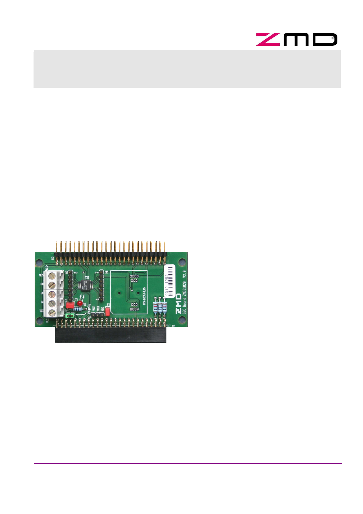
Example: ZMD31020 USB-Evaluation Board
Brief Description
The new modular evaluation kit system of ZMD’s
sensor signal conditioner ICs allows the user a very
simple and intuitive handling of both, evaluation
hardware and software. For the evaluation of different
SSC-ICs only this IC-specific SSC evaluation board
and software has to be interchanged, the other parts
of the evaluation hardware (communication board and
bridge simulator) are almost the same.
The SSC evaluation board allows a simple-to-installevaluation of ZMD’s SSC-IC matching with this board.
Either this IC is assembled directly on the PCB by
soldering (standard version), or is connected via a
common SSOP-ZIF-socket for simple IC-interchange
(optional).
On board there are two 50-pin-connectors for “plug &
play” – connection to the communication board and (if
necessary) to the sensor replacement board.
Alternatively, by the on-board-screw terminal an
external bridge sensor element can be connected too
for a more realistic evaluation.
On-board-LEDs display the status of 5 VDC-power
supply and (depending on SSC-IC-type) the status of
digital outputs (e.g. ALARM 1 and 2 at ZMD31050).
Several strips allow the access to all signal-I/O-lines of
the SSC-IC for a simple system check.
Every SSC-evaluation board type is hard-coded, this
allows its identification by the µC of the
communication board.
Copyright © 2005, ZMD AG, Rev. 1.00, 2005-05-23
All rights reserved. The material contained herein may not be reproduced, adapted, merged, translated, stored, or used without the prior
written consent of the copyright owner. The Information furnished in this publication is preliminary and subject to changes without notice.
1/10
reason of usage of trade, custom or course of dealing.
ZMD31XXX – Evaluation KIT
Datasheet ZMD31XXX Evaluation Board
Important Note
Restrictions in Use
The ZMD31XXX USB Evaluation Kit hardware and ZMD31XXX USB Evaluation Kit software
is designed for IC evaluation, laboratory setup and module development only.
The ZMD31XXX USB Evaluation Kit hard- and software must not be used for module
production and production test setups.
Disclaimer
ZMD AG shall not be liable for any damages arising out of defects resulting from (i)
delivered hard- and software (ii) non-observance of instructions contained in this manual,
or (iii) misuse, abuse, use under abnormal conditions or alteration by anyone other than
ZMD AG. To the extent permitted by law ZMD AG hereby expressly disclaims and user
expressly waives any and all warranties, wether express, implied or statutory, including,
without limitation, implied warranties of merchantability and of fitness for a particular
purpose, statutory warranty of non-infringement and any other warranty that may arise by
CONTENT PAGE
1.
ZMD31020 – USB – EVALUATION BOARD ..............................................3
1.1 ZMD31020 USB EVALUATION BOARD DESCRIPTION ........................................3
1.2 ZMD31020 USB EVALUATION BOARD – SCHEMATICS .....................................3
1.3 ZMD31020 USB EVALUATION BOARD – PCB ................................................4
2. ZMD31030 – USB – EVALUATION BOARD ............................................. 5
2.1 ZMD31030 USB EVALUATION BOARD DESCRIPTION ........................................5
2.2 ZMD31030 USB EVALUATION BOARD – SCHEMATICS .....................................5
2.3 ZMD31030 USB EVALUATION BOARD – PCB ................................................6
3. ZMD31035 – USB – EVALUATION BOARD ..............................................7
3.1 ZMD31035 – EVALUATION BOARD DESCRIPTION..............................................7
3.2 ZMD31035 USB EVALUATION BOARD – SCHEMATICS .....................................7
3.3 ZMD31035 USB EVALUATION BOARD – PCB ................................................8
4. ZMD31035 – USB – EVALUATION BOARD ..............................................9
4.1 ZMD31050 – EVALUATION BOARD DESCRIPTION..............................................9
4.2 ZMD31050 USB EVALUATION BOARD – SCHEMATICS .....................................9
4.3 ZMD31050 USB EVALUATION BOARD – PCB ..............................................10
Copyright © 2005, ZMD AG, Rev. 1.00, 2005-05-23 2/10
All rights reserved. The material contained herein may not be reproduced, adapted, merged, translated, stored, or used without the prior
written consent of the copyright owner. The Information furnished in this publication is preliminary and subject to changes without notice.
GND
ZMD31XXX – Evaluation KIT
Datasheet ZMD31XXX Evaluation Board
1. ZMD31020 – USB – Evaluation board
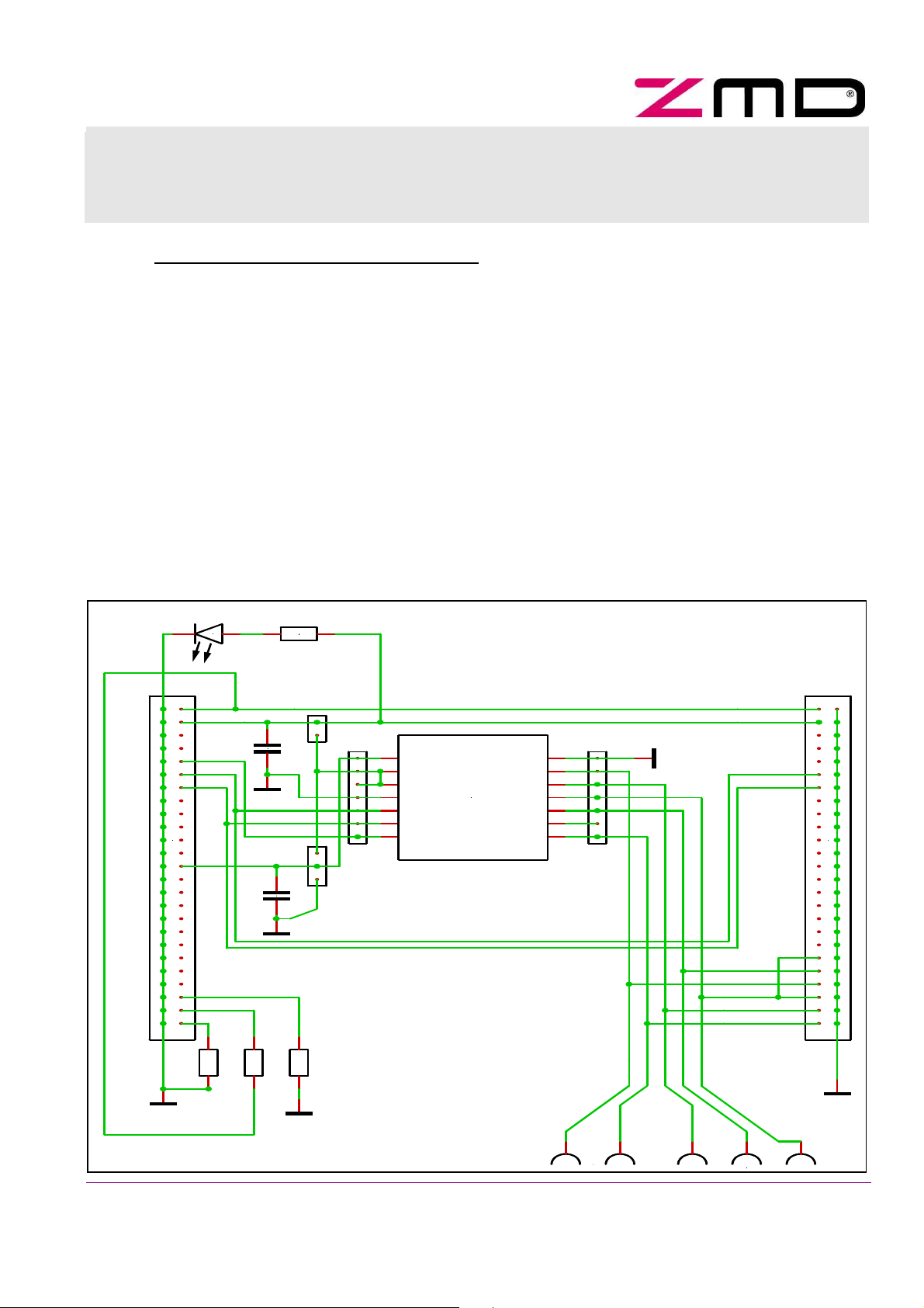
1.1 ZMD31020 USB Evaluation board description
The ZMD31020 Evaluation board is supplied by the regulated 5 VDC-power line controlled by the µC
via a relay of the communication board. Additionally, an on-board-jumper allows the manual cut of the
IC-power supply and a simple measurement of the supply current of the ZMD31020. A red LED
displays the power supply status, its forward current is not included in the measured supply current.
2
The I
stimulus values and the configuration of the ZMD31020. The EEPROM programming voltage VPP is
supplied by the communication board too. The analog output voltage VOUT of the ZMD31020 is
connected with µC-input “ADC 0”, thus a direct processing of this analog signal by the µC is possible.
This board is hard-coded by three resistors on (D7=L / D6 = H / D5 = L). It is connected to the
communication board via a 50-pin-connector (female). On-board there are two strips for a simple
access on bridge sensor signals, VOUT and bridge power supply voltage. Via a second 50-pinconnector (male) the sensor replacement board can be connected. Alternatively, an external bridge
sensor element is connectable by the on-board screw terminal.
1.2 ZMD31020 USB Evaluation Board – Schematics
C-communication between µC and ZMD31020 allows both, the digital readout of measured
L-934LD-rt
2 1
D1
R4
1k
KS5V
21
ZMD31020 SENSOR BOARD
K1
2
4 3
6 5
8 7
10 9
12 11
14 13
16 15
18 17
20 19
22 21
24 23
26 25
28 27
30 29
32 31
34 33
36 35
38 37
40 39
42 41
44 43
46 45
48 47
50 49
GND
1
10kR1
VPP
VOUT
D5
D6
D7
2
1
10kR2
C1
GND
VDDA
10nC2
2
1
5P
K5
1
1
2
2
220n
3
2
K4
1
1
2
GND
2
10kR3
1
K6
1
2
3
4
5
6
7
IC1
VOUT
1
VDDA
2
VDD
3
VSS
4
SCL
5
SDA
6
VPP
7
ZMD31020
VSSA
VSSB
VBP
VDDB1
VTN
VDDB2
VBN
14
13
12
11
10
9
8
7
6
5
4
3
2
1
GND
K7
VBN
VBP
VSSB
VTN
VTN
VSSB
VDDB1
VBP
VBN
VDDB1
5P5P
KS5VKS5V
SCLSCL
SDASDA
1
2
43
65
87
109
1211
1413
1615
1817
2019
2221
2423
2625
2827
3029
3231
3433
3635
3837
4039
4241
4443
4645
4847
5049
GND
K2
21
KL2
KL1
321
Copyright © 2005, ZMD AG, Rev. 1.00, 2005-05-23 3/10
All rights reserved. The material contained herein may not be reproduced, adapted, merged, translated, stored, or used without the prior
written consent of the copyright owner. The Information furnished in this publication is preliminary and subject to changes without notice.

Screw terminal
sensor replacement
ZMD31XXX – Evaluation KIT
Datasheet ZMD31XXX Evaluation Board
1.3 ZMD31020 USB Evaluation Board – PCB
for external
sensor element
Jumper K5
“power supply”
LED D1
“power supply”
Connector K1 to
communication board
Connector K2 to
Copyright © 2005, ZMD AG, Rev. 1.00, 2005-05-23 4/10
All rights reserved. The material contained herein may not be reproduced, adapted, merged, translated, stored, or used without the prior
written consent of the copyright owner. The Information furnished in this publication is preliminary and subject to changes without notice.

ZMD31XXX – Evaluation KIT
Datasheet ZMD31XXX Evaluation Board
2. ZMD31030 – USB – Evaluation board
2.1 ZMD31030 USB Evaluation board description
The ZMD31030 Evaluation board is supplied by the 12 VDC-power line controlled by the µC via a relay
of the communication board. Additionally, an on-board-jumper allows the manual cut of the IC-power
supply and a simple measurement of the supply current of the ZMD31030. A red LED displays the
power supply status, its forward current is not included in the measured supply current.
There are two communication modes between µC and ZMD31030, a common SPI-mode (3-wireinterface directly) and the LIN-mode (1-wire-interface via LIN-transceiver-IC). An on-board-jumper
adjusts the communication mode to be used. Both allows the digital readout of measured stimulus
values and the configuration of the ZMD31030. Additionally, two PWM-output modes (H
or LowSideSwitch) allows the readout of measured stimulus values.
This board is hard-coded by three resistors on (D7=L / D6 = H / D5 = H). It is connected to the
communication board via a 50-pin-connector (female). On, board there are four strips for a simple
access on bridge sensor signals, I/O-signals and bridge power supply voltage. Via a second 50-pinconnector (male) the sensor replacement board can be connected. Alternatively, an external bridge
sensor element and an external temperature sensor are connectable by the on-board screw terminal.
ighSideSwitch
2.2 ZMD31030 USB Evaluation Board – Schematics
L-934LD-rt
2 1
K1
1
2
4 3
6 5
8 7
10 9
12 11
14 13
16 15
18 17
20 19
22 21
24 23
26 25
28 27
30 29
32 31
34 33
36 35
38 37
40 39
42 41
44 43
46 45
48 47
50 49
10kR1
GND
KS12V
DI
SPI
CLK
LIN_1
D5
D6
D7
D1
220p
GND
2
1
R4
21
3,3k
D2
1N4001
2
1
C3
2
10kR3
10kR2
1
1
2
3
21
K8
LIN
10kR6
2
1
KS12V
68 R5
2 1
4
3
2
2
1
1
2 1
K4
GND
R7
2 1
10k
VB
HOUT
LOUT
K3
1
2
C1
ZMD31030 SENSOR BOARD
K5
21
K6
1
2
VB
3
4
5
6
7
8
9
220n
100n
1
2
C2
10
GND
IC1
1
VSSA
2
VDDA
3
HOUT
4
DI
5
CLK
6
VDD
7
VB
8
VSS
9
VSSE
ZMD31030
5P
VTN2
VDDB2
VDDB1
VTN1
VBN
VSSB
VBP
LIN
LOUT
K2
5P5P
KS5VKS5V
SCLSCL
SDASDA
20
19
18
17
16
15
14
13
12
11
10
9
8
7
6
5
4
3
2
K7
110
VDDB2
VBN
VTN2
VSSB
1
2
43
65
87
109
1211
1413
1615
1817
2019
2221
2423
2625
2827
3029
3231
3433
3635
3837
4039
4241
4443
4645
4847
5049
VBP
VDDB1
VTN1
GND
4321
KL2
KL1
321
Copyright © 2005, ZMD AG, Rev. 1.00, 2005-05-23 5/10
All rights reserved. The material contained herein may not be reproduced, adapted, merged, translated, stored, or used without the prior
written consent of the copyright owner. The Information furnished in this publication is preliminary and subject to changes without notice.

crew terminal
sensor replacement
ZMD31XXX – Evaluation KIT
Datasheet ZMD31XXX Evaluation Board
2.3 ZMD31030 USB Evaluation Board – PCB
S
for external
sensor element
LED D1
“power supply”
Jumper K8
“LIN / SPI”
Connector K1 to
communication board
Jumper K5
“power supply”
Connector K2 to
Copyright © 2005, ZMD AG, Rev. 1.00, 2005-05-23 6/10
All rights reserved. The material contained herein may not be reproduced, adapted, merged, translated, stored, or used without the prior
written consent of the copyright owner. The Information furnished in this publication is preliminary and subject to changes without notice.

ZMD31XXX – Evaluation KIT
Datasheet ZMD31XXX Evaluation Board
3. ZMD31035 – USB – Evaluation board
3.1 ZMD31035 – Evaluation board description
The ZMD31035 Evaluation board is supplied by the regulated 5 VDC-power line controlled by the µC
via a relay of the communication board. Additionally, an on-board-jumper allows the manual cut of the
IC-power supply and a simple measurement of the supply current of the ZMD31035. A red LED
displays the power supply status, its forward current is not included in the measured supply current.
The LINwire-communication between µC and ZMD31035 allows both, the digital readout of measured
stimulus values and the configuration of the ZMD31035. The analog output voltage VOUT of the
ZMD31035 is connected with µC-input “ADC 2”, thus a direct processing of this analog signal by the
µC is as possible as the LINwire-communication.
This board is hard-coded by three resistors on (D7=H / D6 = H / D5 = L). It is connected to the
communication board via a 50-pin-connector (female). On, board there are three strips for a simple
access on bridge sensor signals, VOUT and bridge power supply voltage. Via a second 50-pinconnector (male) the sensor replacement board can be connected. Alternatively, an external bridge
sensor element is connectable by the on-board screw terminal.
3.2 ZMD31035 USB Evaluation Board – Schematics
L-934LD-rt
K1
2
4 3
6 5
8 7
10 9
12 11
14 13
16 15
18 17
20 19
22 21
24 23
26 25
28 27
30 29
32 31
34 33
36 35
38 37
40 39
42 41
44 43
46 45
48 47
50 49
2 1
1
AOUT
D5
D6
D7
10kR1
1
D1
1k R4
2
1
2
K4
2 1
100n
C4
1
2
100n
GND
100n
K3
1
C1
2
C2
1
2
3
2
1
1
2
3
4
5
6
7
C3
VDDA
15n
GND
2
2
1
2
10kR2
10kR3
1
1
ZMD31035 SENSOR BOARD
K5
1
2
3
4
5
6
7
IC1
VSSA14VDDB
VDDA
DI
CLK
VDD
VDDE
VSS
VTN
VBN
VSSB
VBP
AOUT
VSSE
13
12
11
10
9
8
ZMD31035
GND
K6
7
6
5
4
3
2
1
VBN
VBP
VSSB
VTN
5P5P
KS5VKS5V
SCLSCL
SDASDA
VTN
VSSB
VDDB
VBP
VBN
VDDB
K2
1
2
43
65
87
109
1211
1413
1615
1817
2019
2221
2423
2625
2827
3029
3231
3433
3635
3837
4039
4241
4443
4645
4847
5049
GND
5P
GND
21
KL2
GND
321
KL1
Copyright © 2005, ZMD AG, Rev. 1.00, 2005-05-23 7/10
All rights reserved. The material contained herein may not be reproduced, adapted, merged, translated, stored, or used without the prior
written consent of the copyright owner. The Information furnished in this publication is preliminary and subject to changes without notice.

Screw terminal
sensor replacement
ZMD31XXX – Evaluation KIT
Datasheet ZMD31XXX Evaluation Board
3.3 ZMD31035 USB Evaluation Board – PCB
for external
Jumper K4
“power supply”
LED D1
“power supply”
Connector K1 to
communication board
sensor element
Connector K2 to
Copyright © 2005, ZMD AG, Rev. 1.00, 2005-05-23 8/10
All rights reserved. The material contained herein may not be reproduced, adapted, merged, translated, stored, or used without the prior
written consent of the copyright owner. The Information furnished in this publication is preliminary and subject to changes without notice.

ZMD31XXX – Evaluation KIT
Datasheet ZMD31XXX Evaluation Board
4. ZMD31035 – USB – Evaluation board
4.1 ZMD31050 – Evaluation board description
The ZMD31050 Evaluation board is supplied by the regulated 5 VDC-power line controlled by the µC
via a relay of the communication board. Additionally, an on-board-jumper allows the manual cut of the
IC-power supply and a simple measurement of the supply current of the ZMD31050. A red LED
displays the power supply status, its forward current is not included in the measured supply current.
There are two communication modes between µC and ZMD31050, a common I
interface) and ZMD’s ZACwire-mode (1-wire-interface). This modes allows both, the digital readout of
measured stimulus values and the configuration of the ZMD31050. The analog output voltage VOUT of
the ZMD31050 is connected with µC-input “ADC 0”, thus a direct processing of this analog signal by
the µC is as possible as the ZACwire-communication.
This board is hard-coded by three resistors on (D7=L / D6 = L / D5 = H). It is connected to the
communication board via a 50-pin-connector (female). On, board there are five strips for a simple
access on bridge sensor signals, I/O-signals and bridge power supply voltage. Via a second 50-pinconnector (male) the sensor replacement board can be connected. Alternatively, an external bridge
sensor element and an external temperature sensor are connectable by the on-board screw terminal.
Two green LEDs display the status of the output signals IO1 and IO2.
2
C-mode (2-wire-
4.2 ZMD31050 USB Evaluation Board – Schematics
L-934LD-rt
K1
2
4 3
6 5
8 7
10 9
12 11
14 13
16 15
18 17
20 19
22 21
24 23
26 25
28 27
30 29
32 31
34 33
36 35
38 37
40 39
42 41
44 43
46 45
48 47
50 49
GND
2 1
1
OUT
IO1
IO2
D5
D6
D7
10kR1
D1
GND
2
?R7
1
2
10kR2
1
1
1k R4
2
ZMD31050 SENSOR BOARD
KS5V
1
2
K5
100nC1
1
K10
1
2
2
3
4
5
K7
1
VDDA
1
2
IN3
2
3
VGATE
3
4
IO1
4
5
IO2
5
6
SCL
6
7
SDA
7
8
VDD
8
C2
ZMD31050
21
100n
IC2
IR_TEMP
1
? C3
2
VINN
VSS
VINP
VBR
FBP
OUT
FBN
IR_TEMP
GND
IO1
2
2
10kR3
1
1
5P
2
1kR5
1
D2
1
2
IO2
2
1kR6
1
1
D3
2
L-934LYD-ge
L-934LGD-gn
2
K3
1
2
K4
1
5P5P
KS5VKS5V
K8
16
15
14
13
12
11
10
9
300 Low TKR8
8
7
6
5
4
3
2
1
1
21
2
3
4
K6
GND
VDDA
IR_TEMP_U
VBR
VINP
VINN
1
2
43
65
87
SCLSCL
SDASDA
109
1211
1413
1615
1817
2019
2221
2423
2625
2827
3029
3231
3433
3635
3837
4039
4241
4443
4645
4847
5049
GND
GND
K2
VBR
VINN
VINP
4321
KL2
VDDA
IN3
IR_TEMP_U
KL1
321
GND
Copyright © 2005, ZMD AG, Rev. 1.00, 2005-05-23 9/10
All rights reserved. The material contained herein may not be reproduced, adapted, merged, translated, stored, or used without the prior
written consent of the copyright owner. The Information furnished in this publication is preliminary and subject to changes without notice.

Screw terminal
sensor replacement
ZMD31XXX – Evaluation KIT
Datasheet ZMD31XXX Evaluation Board
4.3 ZMD31050 USB Evaluation Board – PCB
for external
Jumper K5
“power supply”
Connector K1 to
communication board
Jumper K6
“bridge mode”
LED D1
“power supply”
sensor element
Connector K2 to
“ALARM” - LEDs
For electrical specifications of ZMD’s Sensor Signal Conditioner ICs please
look at the regarding datasheets and functional descriptions.
The information furnished here by ZMD is believed to be correct and accurate. However, ZMD shall not be liable to any licensee or third party
for any damages, including, but not limited to, personal injury, property damage, loss of profits, loss of use, interruption of business or
indirect, special, incidental, or consequential damages of any kind in connection with or arising out of the furnishing, performance, or use of
this technical data. No obligation or liability to any licensee or third party shall result from ZMD’s rendering of technical or other services.
For further
information:
Copyright © 2005, ZMD AG, Rev. 1.00, 2005-05-23 10/10
All rights reserved. The material contained herein may not be reproduced, adapted, merged, translated, stored, or used without the prior
written consent of the copyright owner. The Information furnished in this publication is preliminary and subject to changes without notice.
ZMD AG
Grenzstrasse 28
01109 Dresden, Germany
Phone +49 (0)351-8822-366
Fax +49 (0)351-8822-337
sales@zmd.de
www.zmd.biz
ZMD America, Inc.
201 Old Country Road, Suite 204
Melville, NY 11747, USA
Phone +01 (631) 549-2666
Fax +01 (631) 549-2882
sales@zmda.com
www.zmd.biz
ZMD America, Inc.
15373 Innovation Drive, Suite 110
San Diego, CA 92128, USA
Phone +01 (858) 674-8070
Fax +01 (858) 674-8071
sales@zmda.com
www.zmd.biz
 Loading...