

Page 1

Rangetops, Cooktops,
& DRopins
Installation Guide
and Users Manual
Page 2
Page 3

Enjoy the versatility and high performance cooking power of ZLINE’s
rangetop, cooktop, and dropin collections.
No matter your kitchen needs, these collections offer four to seven
burners in various finishes, sizes, and BTUs. Enjoy precise heat control
through imported Italian burners combined with durable cast iron grills,
both known for their even heat distribution and longevity.
Made by hand and innovatively designed - allowing exploration for the
love of food.
Page 4

CONTENTS
Installation Guide
IMPORTANT SAFETY INSTRUCTIONS 1
WARRANTY AND SERVICE 3
BEFORE INSTALLATION 5
RANGETOP/DROPIN INSTALL 8
INSTALLATION REQUIREMENTS 8
POWER RATING & ELECTRICAL CONNECTION 9
WIRING SCHEMATICS 10
GAS CONNECTION 13
GAS CONVERSION PROCEDURE 17
INSTALLATION CHECKLIST 20
FINAL PREPARATION 20
Page 5

CONTENTS
Users Manual
ROOM VENTILATION 22
COOKTOP COOKING 23
MAINTAINING YOUR RANGE 25
TROUBLESHOOTING 26
Page 6

Thank You
We want to thank you for choosing one of our beautiful, professional ranges. We
know that you have many brands to choose from and we are thrilled that you have
decided to place one of our products in your home.
Our appliances are designed according to the strictest safety and performance
standards for the North American market. We follow the most advanced
manufacturing process. Each appliance leaves the factory after thorough quality
inspection and testing. Our distributors and our service partners are ready to answer
any questions you may have regarding installation of your ZLINE product.
This manual will help you learn to use the product in the safest, most efficient manner,
and care for it so that it may give you the highest satisfaction for years to come.
This manual also includes directions for the professional installer that will install the
product in your home. We recommend professional installation by trained personnel.
Please keep this manual for future use.
Page 7
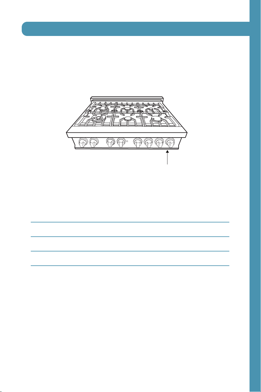
Location of Appliance Tags
The rating tag shows the model and serial number of your range. The tag is located
under the front edge of the range cooktop.
Appliance Tag Here
Important Appliance Information
Dealer
Model
Date Installed
Installer
Page 8
Important Safety Instructions
An air curtain or other overhead range/cooktop hood which
WARNING
The manufacturer will not be responsible for any damage to property or to persons
caused by incorrect installation, improper use of the appliance, or failure to heed the
warnings listed.
The manufacturer reserves the right to make changes to its products when considered
necessary and useful, without affecting the essential safety and operating
characteristics.
Before beginning installation, please read these instructions completely and carefully.
Do not remove permanently affixed labels, warnings, or plates from the product.
This will void the warranty. Please observe all local, state and national codes and
ordinances.
Please ensure the range is properly grounded. The installer should leave these
instructions with the consumer who should retain for local inspectors use and for
future reference. The plug should always be accessible. Installation must conform with
local codes or in the absence of codes, the National Fuel Gas Code NSIZ223. 1/
NFPA54. Electrical installation must be in accordance with the National electrical
code ANSI/NPA70-latest edition and/or local codes. In Canada: Installation must
be in accordance with the current CAN/CGA-fe 149.1 National gas installation
code or CAN/CGA-B 149.2, Propane installation code and/or local codes.
Electrical installation must be in accordance with the current CSA C22.1 Canadian
electrical codes Part 1 and/or local codes.
Installation of any gas-fired equipment should be made by a licensed plumber. A
manual gas shut-off valve must be installed in the gas supply line for safety and ease
of service.
operates by blowing downward airflow onto the range, shall not be
used/installed in conjunction with this gas range.
1
Page 9
Important Safety Instructions
Important Safety Information
Please read and follow these important instructions for the safety of your home and
the people living in it.
If the information in this manual is not followed exactly, a fire or
WARNING
Do not store or use gasoline or any other flammable substances in the vicinity of this
or any other appliance.
WARNING
What To Do If You Smell Gas
DO NOT light any appliance.
DO NOT touch any electrical switch.
DO NOT use any phone in your building.
DO NOT use any aerosol cans or combustibles.
Immediately call your gas supplier from a neighbor’s phone, follow the gas supplier’s
instructions.
In the case you cannot reach the gas supplier, call the fire department.
Installation and service must be conducted by a qualified installer, service agency, or
the gas supplier.
explosion may result causing property damage, personal injury, or
death.
Never use this appliance as a space heater to heat or warm the
room. Doing so may result in carbon monoxide poisoning.
2
Page 10

Warranty and Service
Warranty and Service
All range products carry a one year parts warranty and includes service, if required.
Service on all products shall be carried out by industry professionals only. For
warranty service, please call customer service.
Replacement Parts
Only authorized replacement parts may be used in performing service on this
appliance.
Replacement parts are available from ZLINE. Call 1-614-777-5004.
3
Page 11
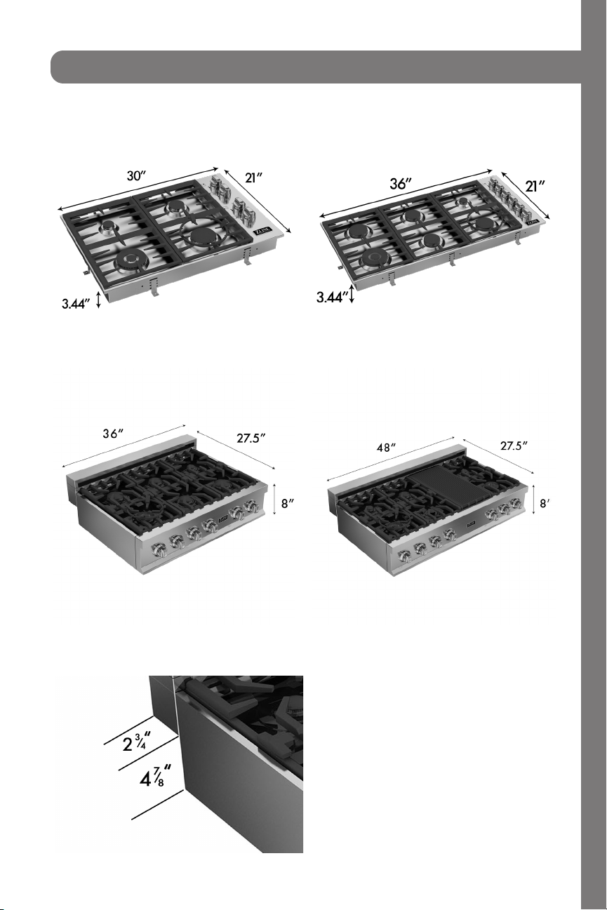
Dropins:
Cooktops:
Product Dimensions
Cooktop cut outs:
4
Page 12

Before Installation
This appliance shall only be installed by an authorized professional.
The appliance shall be installed in accordance with the standards of the country
where it will be installed. The installation of this appliance must conform to local
codes and ordinances. In the absence of local codes installation must conform to
American National Standards, National fuel Gas code ANSI Z223.1-Latest edition/
NFPA 54 or B 149.1.
The appliance, when installed, must be electrically grounded in accordance with
local codes or, in the absence of local codes, with the National Electrical code,
ANSI/NFPA 70.
If local codes permit, a flexible metal appliance connections with the new AGA or
CGA certified design, max 5 feet (1.5m) long, 34˝m is recommended for connecting
this appliance to the gas supply line. DO NOT bend or damage the flexible
connector when moving the appliance.
This appliance must be used with the pressure regulator provided. The regulator must
be properly installed in order to be accessible when the appliance is installed in
its final location. The pressure regulator must be set for the type of gas to be used.
The pressure regulator has 34˝ female pipe thread. The appropriate fitting must be
determined based on the size of your gas supply line, the flexible metal connector
and the shut-off valve.
The appliance must be isolated from the gas supply piping system by closing its
individual manual shut-off valve during any pressure testing of the gas supply piping
system at test pressures equal to or less than 34 PSI(13,8w.cpr 3,5kPA).
All opening holes in the wall and floor, back and under the appliance shall be sealed
before installation of the appliance.
A manual valve shall be installed in an accessible location in the gas line external to
the appliance for the purpose of turning on and shutting off the gas to the appliance.
WARNING
Do not use aerosol sprays in the vicinity of this appliance while it is hot.
5
Page 13

Before Installation
Room Ventilation
An exhaust fan may be used with the appliance; in each case it shall be installed
in conformity with the appropriate national and local standards. Exhaust hood
operation may affect other vented appliances; in each case it shall be installed in
conformity with the appropriate national and local standards.
Type of Gas
This appliance is shipped from the factory for use with natural gas. For use with
propane LP gas, please follow the conversion procedure described on pg. 18. A step
by step conversion procedure is also included with each set of LP gas nozzles.
Gas Pressure
The maximum inlet gas supply pressure incoming to the gas appliance pressure
regulator is 34PSI (13,8w. cpr 3,5kPA).
The minimum gas supply pressure for checking the regulator setting shall be at least
1˝ w.c (249 Pa) above the inlet specified manifold pressure to the appliance (This
operating pressure is 4˝ w.c. (1.00kPa) for Natural gas and 11˝ w.c. (2.75 kPa) for
LP gas.
Gas cooktop requires 1”- 6” side wall spacing above the counter height for
proper combustion. Please review specific model installation instructions for
required dimensions. 30 inches between the cooktop and bottom of the cabinet
above. 0.25 inches for sides below countertop height.
NOTE: Please consult your local building codes for variations with installation.
6
Page 14

Range Top/Dropin Installation
Attaching the dropin
To prevent liquids from accidentally leaking into
the underlying storage space, the appliance is
equipped with a special gasket. To apply this
gasket, carefully follow the instructions in Fig.
1. Lay out the protective sealing strips along
the edges of the opening in the bench top and
carefully overlap the strip end. (See Fig. 1).
insert the dropin into the bench top opening.
With a screwdriver assemble the brackets (A) to
the hotplate bottom by means of the screws (B)
(See Fig. 2). Slide the hooks into position and
secure them with the screws. Trim the part of the
sealing strips that extend beyond the dropin
base.
Gas Connection
Please review gas connection on page 12.
7
Page 15

Installation Requirements
A properly grounded and horizontally-mounted electrical receptacle type NEMA 14-
50R should be installed no higher than 3” above the floor, no less than 2” and not
more than 8” from the left side (facing product); refer to electrical connection section.
Gas
An agency-approved, properly-sized manual shut-off valve should be installed no
higher than 3” above the floor and no less than 2” and no more than 8” from the
right side (facing product).
To connect gas between shut-off valve and regulator, use agency-approved,
properly sized flexible or rigid pipe. Check all local code requirements.
Installation Adjacent to Kitchen Cabinets
For the best look, the worktop should be level with the cabinet countertop.
8
Page 16

Power Rating & Electrical Connection
The appliance shall be connected to a single phase electric line rated at 110-120Vac
and 60Hz frequency. The true voltage in most homes is usually between these values.
Electric Power Rating
110/120 Vac: 12A Max
Electrical Grounding
Our gas oven is equipped with a three-prong plug for your protection against shock
hazard and should be plugged directly into a properly grounded receptacle. Do not
cut or remove the prong from this plug.
Disconnect electrical power at the circuit breaker box or fuse box
before installing the appliance.
WARNING
Provide appropriate ground for the appliance. Use copper
conductors only.
9
Page 17

Wiring Schematics
RA30(RAB30-RAS30)电路图
RA36(RAB36-RAS36)电路图
Model: RC/RC-PBT-30
Heat pipes-up
(INSIDE1800/2395 W,
OUTSIDE 650/865 W)
Heat pipes-down
2000/2670W
(LIFT)
oven fan
(LIFT)
oven fan
120/208 V Ac 60Hz
120/240 V Ac 60Hz
(RIGHT)
oven fan
SWITCH FOR
ELECTRIC OVEN
case fan
(LIFT)
LAMP
白色
(RIGHT)
LAMP
RED
WHITE
BROWN
SWITCH FOR
THERMOSTAT
THERMOSTAT
Model: RC/RC-PBT/RT/RTB/RTS-36
120/208 V Ac 60Hz
120/240 V Ac 60Hz
(RIGHT)
oven fan
INDICATOR
LIGHT
RED
WHITE
BROWN
GREEN
WIRE CONNECTOR
SNAP
SWITCH
SWITCH
FOR LAMP
GREEN
WIRE CONNECTOR
GROUND
WIRE
IGNITION
ALLUMAGE
MICROSWITCH 1
MICROSWITCH 2
MICROSWITCH 3
MICROSWITCH 4
GROUND
WIRE
Heat pipes-up
(INSIDE1800/2395 W,
OUTSIDE 650/865 W)
Heat pipes-down
2000/2670W
SWITCH FOR
ELECTRIC OVEN
case fan
(LIFT)
LAMP
(RIGHT)
LAMP
SWITCH FOR
THERMOSTAT
SNAP
THERMOSTAT
SWITCH
SWITCH
FOR LAMP
IGNITION
MICROSWITCH 1
MICROSWITCH 2
MICROSWITCH 3
MICROSWITCH 4
MICROSWITCH 5
MICROSWITCH 6
ALLUMAGE
10
Page 18

Wiring Schematics
RA30(RAB30-RAS30)电路图
Model: RT/RTB/RTS-48
Heat pipes-up
(INSIDE1800/2395 W,
OUTSIDE 650/865 W)
Heat pipes-down
2000/2670W
(LIFT)
oven fan
120/208 V Ac 60Hz
120/240 V Ac 60Hz
(RIGHT)
oven fan
SWITCH FOR
ELECTRIC OVEN
case fan
(LIFT)
LAMP
白色
(RIGHT)
LAMP
RED
WHITE
BROWN
GREEN
WIRE CONNECTOR
SWITCH FOR
THERMOSTAT
THERMOSTAT
SWITCH
FOR LAMP
SNAP
SWITCH
GROUND
WIRE
IGNITION
ALLUMAGE
MICROSWITCH 1
MICROSWITCH 2
MICROSWITCH 3
MICROSWITCH 4
11
Page 19

GAS CONNECTION
All gas connections must comply with national and local codes. The gas supply
line (service) must be the same size or greater than the inlet line of the appliance.
This range uses a ½˝ NPT inlet. Use appropriate sealant on all pipe joints that are
resistant to gas.
This range can be used with Natural or LP/propane gas. The range is shipped from
the factory for use with natural gas.
For LP/Propane household installation, the appliance must be converted by the
dealer, factory-trained professional, or qualified licensed plumber or gas service
company.
Gas conversion is important for safe and effective use of the appliance. It is the
responsibility of the dealer and the owner of the range to perform the appropriate
gas conversion following the directions of the manufacturer.
The gas conversion procedure is described in this manual and in the package
containing the conversion nozzles shipped with every range.
Please provide the service person with this manual before work is started on the
range.
WARNING
DO NOT use an open flame when checking for leaks.
Leak testing of the appliance shall be conducted according to the manufacturer’s
instructions. Before operating the appliance, always check for leaks with soapy
water solution or other acceptable method. Check for gas leakage with soapy
water solutions on all gas connections between inlet gas pipes of the appliance, the
gas regulator and, the manual shut-off valve. Bubbles will form with a soapy water
solution if there is a leak.
12
Page 20

Gas Connection
Manual Shut-Off Valve
This valve is not shipped with the appliance and must be provided by the installer.
The manual shut-off valve must be installed in the gas service line between the gas
hook-up on the wall and the appliance inlet, in position where it can be reached
quickly in the event of an emergency.
In Massachusetts: A T handle type manual gas shut-off valve must be installed in the
gas supply line to this appliance.
Flexible Connections
In case of installation with flexible couplings and/or quick-disconnect fittings, the
installer must use a heavy duty, AGA design-certified commercial flexible connector
of at least ½˝ (1.3cm) IF NPT (with a suitable strain relief in compliance with ANSI
Z21.41 and Z21.69 standards.
In Massachusetts: The unit must be installed with a 36˝ (3 foot long) flexible gas
connector.
In Canada: Use CAN 1-6. 10-88 metal connectors for gas appliances and CAN
1-6.9 M79 quick disconnect device for use with gas fuel.
Pressure Test Point Stopper Valve
To avoid gas leaks, the pressure test-point stopper valve and gasket supplied with the
range must be installed on the gas fitting at the back of the range according to the
diagram below.
Gas pipe
Gasket
Gas connection adaptor 1/2” NPT with
pressure test point 1/8” NPT (to be fixed
toward external side of the appliance)
Pressure test-point stopper
13
Page 21

Gas Connection
Pressure Regulator
Since service pressure may fluctuate with local demand, every gas cooking
appliance must be equipped with a pressure regulator on the incoming service line
for safe and efficient operation.
Pressure Regulator
The pressure regulator shipped with the appliance has two female threads 34”NPT.
The regulator shall be installed properly in order to be accessible when the appliance
is installed in its final position.
Manifold pressure should be checked with a manometer and comply with the values
indicated below.
Natural Gas->4.0”W.c.P
L P/Propane-> 10.0” W.c.P
Incoming line pressure upstream from the regulator must be 1˝ W.C.P. higher than the
manifold pressure in order to check the regulator.
The regulator used on this range can withstand a maximum input pressure of ½
PSI (13.8˝ W.C or 3.5kPa) If the line pressure exceeds that amount, a step down
regulator is required.
The appliance, its individual shut-off valve, and the pressure regulator must be
disconnected from the gas line during any pressure testing of that system at pressures
in excess of ½ PSI (13.8˝ W.c or 3.5kPa).
WARNING
Before carrying out this operation, disconnect the appliance from gas
and electricity.
Gas conversion shall be conducted by a factory-trained professional.
14
Page 22

Gas Connection procedure
The gas conversion procedure for this range includes:
1. Pressure Regulator
2. Surface Burners
3. Flame Adjustment
The conversion is not finished if all steps are not completed.
Before performing the gas conversion, locate the package containing the
replacement nozzles, which has a number indicating its flow diameter printed on the
body. Consult the table below for matching nozzles to burners.
Save the nozzles removed from the range for future use.
Propane
Conversion
Video
15
LPG: Liquid Propane Gas
NG: Natural Gas
Page 23

Gas Connection procedure
16
Page 24

Gas Conversion Procedure
Step 1: Pressure Regulator
The pressure regulator supplied with the appliance is a convertible type pressure
regulator for use with Natural Gas at a nominal outlet pressure of 4˝ w.c. or LP gas
at a nominal outlet pressure of 11” w.c. and it is pre-assembled from the factory
to operate with one of these gas pressure as indicated in the labels affixed on the
appliance, package and instruction booklet.
To convert the regulator for use with other liquid propane LP gas:
1. Unscrew the upper cap of the regulator, reverse its direction, and screw it in firmly
against the cap.
2. Screw the metal cap, by hand, in the original position on the regulator.
Gas Conversion Procedure
17
5/8
Reverse regulator
screw and spring.
Page 25

Gas Conversion Procedure
Step 2: Surface Burners
To replace the nozzles of the surface burners, lift up the burners and unscrew the
nozzles shipped with the range using a 7 mm (socket wrench).
Replace nozzles using the conversion set supplied with the range. Each nozzle has a
number indicating its flow diameter printed on the body. Consult the table on page
15 for matching nozzles to burners.
Step1
Step 2
Step 4
9/32
NG LPG
Step 3
Step 5
9/32
NG = Natural Gas
LPG = Liquid Propane Gas
18
Page 26

Gas Conversion Procedure
Step 3:
1. Light one burner at a time and set it to the MINIMUM position (small flame).
2. Remove the knob.
3. The range is equipped with a safety valve. Using a small-size flathead screwdriver,
locate the choke screw (see diagram below) and turn to the right or left until the
burner flame is adjusted to desired minimum.
4. Make sure that the flame does not go out when switching quickly from the
MAXIMUM to the MINIMUM position.
The high flame setting cannot be adjusted to be lower. If the height is
too high, revisit the conversion set up. A step may have been missed.
Flame Adjustment
19
Flame
Adjustment
Video
2.0 x 50 mm
2.0 x 50 mm
Page 27

Installation Checklist
1. Is the back guard securely connected?
2. Is the electricity properly grounded?
3. Is the gas service line connected following the directions of the manufacturer?
4. Have all the proper valves, stoppers, and gaskets been installed between the
range and the service line?
5. Has the gas connection been checked for leaks?
6. Has the range been setup for the type of gas available in the household? (propane
or natural gas)
7. Does the flame appear sharp blue with no yellow tipping?
8. Has the minimum setting for all burners been adjusted?
9. Have the cooktop flames been adjusted to customer preference?
Final Preparation
All stainless steel body parts should be wiped with hot, soapy water and with a
stainless steel cleanser.
If build-up occurs, do not use steel wool, abrasive cloths, cleaners, or powders. If it is
necessary to scrape stainless steel to remove encrusted materials, soak with hot, wet
cloths to loosen the material, and then use a wood or nylon scraper. DO NOT use
a metal knife, or any other metal tool to scrape stainless steel! Scratches are almost
impossible to remove.
20
Page 28

Users Manual
21
Page 29

Room Ventilation
The use of a gas cooking appliance generates heat and humidity in the room where
it is installed. Proper ventilation in the room is needed. Make sure the kitchen is
equipped with a range hood of appropriate power (400 CFM minimum). Activate
the exhaust fan/range hood when possible. Intensive and continuous use of the
appliance may require additional ventilation, for example, by opening a window.
22
Page 30

COOKTOP COOKING
A
B
A
B
Correct
Incorrect
Correct Incorrect
A
B
A
B
A
B
Correct
Incorrect
A
B
Surface Burner Operation - Electric Ignition
To activate the electric ignition, simply turn the control knob counter-clockwise to
maximum power, then press the knob in to start the flow of gas and the ignition spark.
The spark will be released at the metal tip of the white ceramic pin located on the side
of the burner. Once the flame is on, release the control knob gently. If the flame turns
off, simply repeat the above procedure.
DO NOT ignite the burners if the black burner cap is not installed or
WARNING
Manual Ignition
Manual ignition is always possible even when the power is cut off or in the event of
a power failure. Turn the control knob counter-clockwise to the MAXIMUM position;
light the flame with a kitchen lighter or with a match.
Using the Burners Correctly
Keep children at a safe distance from the appliance during
WARNING
operation. DO NOT allow children to operate the appliance!
not centered, the flame will be irregular.
1. Always check that the burner caps are properly installed before operation:
2. Verify that the flame of the worktop burners is completely blue and with a regular
aspect as shown below:
3. Always adjust the burner flame so it does not extend beyond the edge of the pan.
23
A
A
B
B
Correct
A
B
Incorrect
Page 31

Symbols:
COOKTOP COOKING
Be sure to set all worktop/broiler burner controls to the OFF position after each use
of the appliance.
Cooktop Functions Selector
OFF
Maximum temperature setting/recommended control knob position for burner
ignition.
Minimum Temperature Setting
Appliance with Worktop Gas Valves
Alternative Type
Note: When igniting a burner, all burners will spark, but only the burner’s knob you
are using will ignite the flame.
The flame color should always be blue. Flickers of orange and
yellow are acceptable. If flames appear orange or yellow and stay
WARNING
that way, check the surrounding area. Candles, cleaning products,
and other changes in atmosphere can affect the flame color.
24
Page 32

Maintaining Your Range
Cleaning Your Range
During cleaning operation never move the appliance from its original
WARNING
Cleaning after Installation: Use a stainless steel cleaning product or wipe to eliminate
the glue residues of the protection film after removal.
Cleaning the Worktop: Periodically clean the burner heads, the cast iron pan
supports, and the burner caps using warm water. Remove burner food and fat
residues with a rubber spatula.
Cleaning Stainless Steel: For the best results, use a stainless steel cleaner product
with a soft sponge or cloth with a warm soap and water solution. Never use abrasive
powders or liquids.
Cleaning the Burner Caps: Lift the burner caps from the burner heads and wash them
in a warm soap and water solution. Dry thoroughly before using them again. Before
reinstalling them on the burner head, check that the gas flow holes are not clogged
with food residues or cleaning products.
Cleaning Enamel: Enameled parts should be cleaned frequently with warm soap
and water solution applied with a soft sponge or wipe. Never use abrasive powders
or liquids! Do not leave acid or alkaline substances on the enameled parts (such
as vinegar, lemon juice, salt, tomato sauce etc.) Use a rubber spatula to remove fat
residues.
installation position. Never use abrasive cleaners! Scratches on the
stainless steel surfaces are permanent. Do NOT clean the range when hot!
25
Page 33

Troubleshooting
Problem
Range does not function
Igniter does not work
Igniter sparking taut; no flame ignition
Burner ignites but flame is large,
distorted, or yellow
Possible Cause and/or Remedy
Range is not connected to electrical power. Check
power circuit breaker, wiring, and fuses.
Gas supply valve is in the “OFF” position or gas
supply is interrupted.
Burner ports are clogged or the unit is not set to
the appropriate gas type. Call a technician to
repair.
The air quality of the room is affecting the flame
color. Ensure that there are no candles, cleaning
products, etc. in the room.
26
Page 34

Kitchen and Bath
Three Locations:
350 Parr Circle
Reno, NV 89512
916 Delaware Avenue
Marysville, OH 43040
319 Rowland Mill Road
Bruceton, TN 38317
www.zlinekitchen.com
1-614-777-5004
 Loading...