

Page 1

Dual Fuel Ranges
1
Page 2
CONTENTS
Installation Guide
IMPORTANT SAFETY INSTRUCTIONS 1
WARRANTY AND SERVICE 3
BEFORE INSTALLATION 5
INSTALLING THE LEGS 7
INSTALLATION REQUIREMENTS & 8
POWER RATING & ELECTRICAL CONNECTION 10
WIRING SCHEMATICS 11
GAS CONNECTION 13
GAS CONVERSION PROCEDURE 16
INSTALLATION CHECKLIST 22
FINAL PREPARATION 22
Page 3
CONTENTS
Users Manual
ROOM VENTILATION 24
SURFACE BURNER LAYOUT 24
OVEN COOKING 25
USING THE OVEN 26
MAINTAINING YOUR RANGE 31
TROUBLESHOOTING 32
Page 4
Thank You
We want to thank you for choosing one of our beautiful professional ranges. We
know that you have many brands to choose from and we are thrilled that you have
decided to place one of our products in your home.
Our appliances are designed according to the strictest safety and performance
standards for the North American market. We follow the most advanced
manufacturing process. Each appliance leaves the factory after thorough quality
inspection and testing. Our distributors and our service partners are ready to answer
any questions you may have regarding installation of your ZLINE product.
This manual will help you learn to use the product in the safest, most efficient manner,
and care for it so that it may give you the highest satisfaction for years to come.
This manual also includes directions for the professional installer that will install the
product in your home. We recommend professional installation by trained personnel.
Please keep this manual for future use.
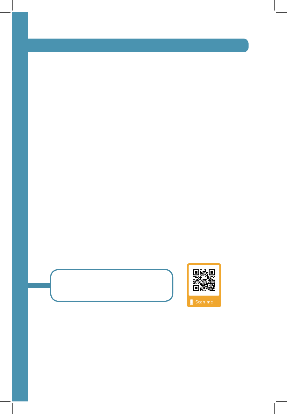
We may have a more up to date manual!
Scan this QR code for a digital copy of the
most recent manual for this appliance.
Page 5
Location of Applicance Tags
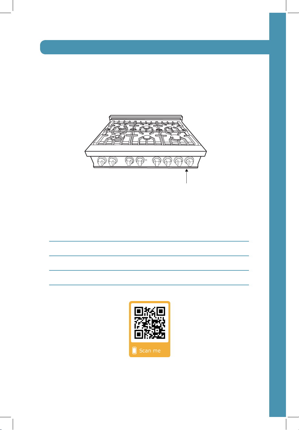
The rating tag shows the model and serial number of your range. The tag is located
under the front edge of the range cooktop. The tag is visible when the oven door is
open.
Appliance Tag Here
Important Appliance Information
Dealer
Model
Date Installed
Installer
Range Installation Video
Page 6
Important Safety Instructions
An air curtain or other overhead range, range, cooktop hood which
WARNING
The manufacturer will not be responsible for any damage to property or to persons
caused by incorrect installation or improper use of the appliance.
The manufacturer reserves the right to make changes to its products when considered
necessary and useful, without affecting the essential safety and operating
characteristics.
This appliance has been designed for non-professional, domestic use only. Do not
place any pot or pan on the open oven door, the door is made of glass and can
break under the weight.
Before beginning installation, please read these instructions completely and carefully.
Do not remove permanently affixed labels, warnings, or plates from the product.
This may void the warranty. Please observe all local, state and national codes and
ordinances. Please ensure the range is properly grounded. The installer should leave
these instructions with the consumer who should retain for local inspectors use and
for future reference. The plug should always be accessible. Installation must conform
with local codes or in the absence of codes, the National Fuel Gas Code NSIZ223.
1/NFPA54. Electrical installation must be in accordance with the National electrical
code ANSI/NPA70-latest edition and/or local codes. In Canada: Installation must
be in accordance with the current CAN/CGA-fe 149.1 National gas installation
code or CAN/CGA-B 149.2, Propane installation code and/or local codes.
Electrical installation must be in accordance with the current CSA C22.1 Canadian
electrical codes Part 1 and/or local codes.
Installation of any gas-fired equipment should be made by a licensed plumber. A
manual gas shut-off valve must be installed in the gas supply line ahead of the oven
in the gas flow for safety and ease of service.
operates by blowing downward airflow onto the range, shall not be
used/installed in conjunction with this gas range.
1
Page 7
Important Safety Instructions
Important Safety Information
Please read and follow these important instructions for the safety of your home and
the people living in it.
If the information in this manual is not followed exactly, a fire or
WARNING
Do not store or use gasoline or any other flammable substances in the vicinity of this
or any other appliance.
WARNING
What To Do If You Smell Gas
DO NOT light any appliance.
DO NOT touch any electrical switch.
DO NOT use any phone in your building.
Immediately call your gas supplier from a neighbor’s phone, follow the gas supplier’s
instructions.
In the case you cannot reach the gas supplier, call the fire department.
Installation and service must be conducted by a qualified installer, service agency, or
the gas supplier.
explosion may result causing property damage, personal injury, or
death.
Never use this appliance as a space heater to heat or warm the
room. Doing so may result in carbon monoxide poisoning and
overheating of the oven.
2
Page 8
Warranty and Service
Warranty and Service
All range products carry a one year parts warranty. Service on all products shall be
carried out by factory-trained professionals only. For warranty service, please call
customer service.
Replacement Parts
Only authorized replacement parts may be used in performing service on this appli-
ance.
Replacement parts are available from ZLINE. Call 1-614-777-5004.
3
Page 9
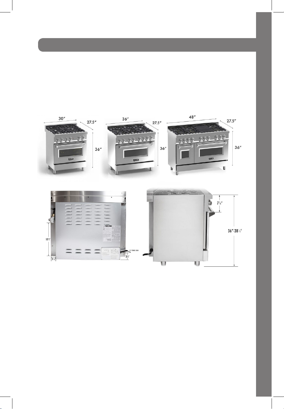
Product Dimensions
Internal Dimensions
48” Model: 26.5” W/12.5”W x 18.5”D x 14”H
36” Model: 30.5”W x 18.5”D x 14”H
30” Model: 26.5” W x 18.5”D x 14”H
4
Page 10
Before Installation
This appliance shall only be installed by an authorized professional.
The appliance shall be installed in accordance with the standards of the country
where it will be installed. The installation of this appliance must conform to local
codes and ordinances. In the absence of local codes installation must conform to
American National Standards, National fuel Gas code ANSI Z223.1-Latest edition/
NFPA 54 or B 149.1.
The appliance, when installed, must be electrically grounded in accordance with
local codes or, in the absence of local codes, with the National Electrical code,
ANSI/NFPA 70.
If local codes permit, a flexible metal appliance con-nections with the new AGA
or CGA certified design, max 5 feet (1,5m) long, 34˝ I.D. is recommended for
connecting this appliance to the gas supply line. DO NOT bend or damage the
flexible connector when moving the appliance.
This appliance must be used with the pressure regulator provided. The regulator must
be properly installed in order to be accessible when the appliance is installed in
its final location. The pressure regulator must be set for the type of gas to be used.
The pressure regulator has 34˝ female pipe thread. The appropriate fitting must be
determined based on the size of your gas supply line, the flexible metal connector
and the shut-off valve.
The appliance must be isolated from the gas supply piping system by closing its
individual manual shut-off valve during any pressure testing of the gas supply piping
system at test pressures equal to or less than 34 PSI(13,8w.cpr 3,5kPA).
All opening holes in the wall and floor, back and under the appliance shall be sealed
before installation of the appliance.
A manual valve shall be installed in an accessible location in the gas line external to
the appliance for the purpose of turning on and shutting off the gas to the appliance.
Do not use aerosol sprays in the vicinity of this appliance while it is
WARNING
in operation.
5
Page 11
Before Installation
Room Ventilation
An exhaust fan may be used with the appliance; in each case it shall be installed
in conformity with the appropriate national and local standards. Exhaust hood
operation may affect other vented appliances; in each case it shall be installed in
conformity with the appropriate national and local standards.
Type of Gas
This appliance is shipped from the factory for use with natural gas. For use with
propane LP gas, please follow the conversion procedure described on pg. 18. A step
by step conversion procedure is also included with each set of LP gas nozzles.
Gas Pressure
The maximum inlet gas supply pressure incoming to the gas appliance pressure
regulator is 34PSI (13,8w. cpr 3,5kPA).
The minimum gas supply pressure for checking the regulator setting shall be at least
1˝ w.c (249 Pa) above the inlet specified manifold pressure to the ap-pliance (This
operating pressure is 4˝ w.c. (1.00kPa) for Natural gas and 11˝ w.c. (2.75 kPa) for
LP gas.
Gas cooktop requires 1”- 6”side wall spacing above the counter height for
proper combustion. Please review specific model installation instructions for
required dimensions. 30 inches between the cooktop and bottom of the cabinet
above. 0.25 inches for sides below countertop height.
NOTE: Please consult your local building codes for variations with installation.
6
Page 12
Installing the Legs
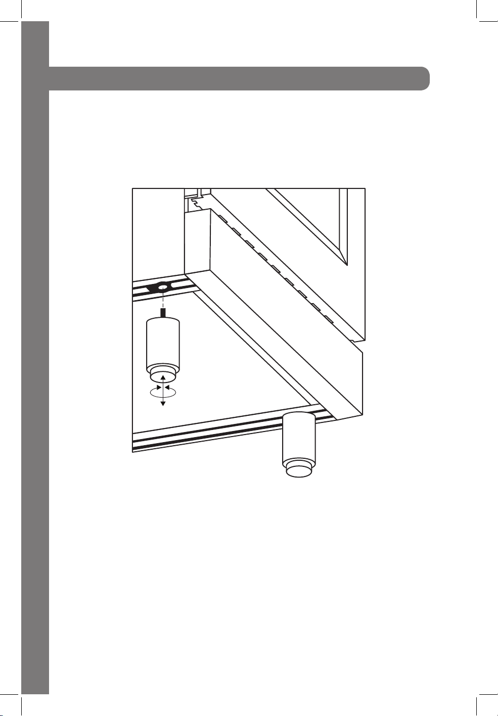
Installing the Legs
The ranges must be used with the legs properly installed. Four height-adjustable legs
are shipped with the range, in a foam container above the range.
1. Before installing the legs, position the appliance near its final location as the legs
are not suitable for moving the appliance over long distances.
2. After unpacking the range, raise it enough to insert the legs in the appropriate
receptacles situated on the lower part of the appliance. Lower the range gently to
keep any undue strain from legs and mounting hardware.
3. Adjust leg height to the desired level by twisting the inside portion of the leg
as-sembly until the proper height is reached. Check with a level that the cooktop is
perfectly level.
7
Page 13

Installation Requirements
A properly grounded and horizontally-mounted electrical receptacle type NEMA 14-
50R should be installed no higher than 3” above the floor, no less than 2” and not
more than 8” from the left side (facing product); refer to electrical connection section.
Gas
An agency-approved, properly-sized manual shut-off valve should be installed no
higher than 3” aboce the floor and no less than 2” and no more than 8” from the
right side (facing product).
To connect gas between shut-off valve and regulator, use agency-approved,
properly sized flexible or rigid pipe. Check all local code requirements.
Installation Adjacent to Kitchen Cabinets
The range may be installed directly adjacent to existing coutertop height cabinets
(36”) from the floor.
For the best look, the worktop should be level with the cabinet countertop. This can be
accomplished by raising the unit using the adjustment spindles on the legs.
ATTENTION: the range CANNOT be installed directly adjacent to kitchen walls, tall
cabinets, tall appliances, or other vertical surfaces above 36˝ high. The minimum
side clearance in such cases is 6”.
Wall cabinets with minimum side clearance must be installed 30˝ above the
countertop with coun-tertop height between 35.5” and 37.25”. The maximum depth
of wall cabinets above the range shall be 13”.
8
Page 14

Cooking Range
Installation Requirements
Side View
13 ”
27 ¹/₂”
location of gas
and electrical
extends on floor
2 ³/₄”
36-38”
to cooking
surface
30”
6”
18
Front View
opening width
3.23”
3.23”
5 ³/₄”
2”
9 ³/₄”
30” to 36”
to bottom of
ventilation hood
W
Opening Width
30” Model 30”
36” Model 36”
48” Model 48”
gas
12”
gas
5”
9
Page 15

Oven Circ. Element: 3200 Watts
Power Rating & Electrical Connection
The appliance shall be connected to a single phase electric line rated at 120Vac and
60Hz frequency.
Electric Power Rating
Recommended voltage of 120/240 Vac: 12A Max
If voltage is less than 120/240 then preheat times may vary.
Heating Element Power Rating
Gas Model: Electric Model:
Oven Bake (Gas): 18,000 BTU Oven Bake (Electric): 1500 Watts
Oven Broil (Gas): 13,000 BTU Oven Broil (Electric): 2850 Watts
Install suitable electric power supply receptacle connection type NEMA 14-50R able
to support a load of at least 30 A (Per Line) according to local code requirements.
For four wires power supply connection system (see diagram below).
Four-Wire Connection
Receptacle
NEMA 14-50R
L2 (red)
N (white)
cable from
power supply
G (green)
L1 (black)
L2 (red)
N (white)
G (green)
L1 (black)
Electrical Grounding
Our electric oven (RA30/36/48) is equipped with a four-prong plug and our gas
oven (RG30/36) is equipped with a three-prong plug for your protection against
shock hazard and should be plugged directly into a properly grounded receptacle.
Do not cut or remove the prong from this plug.
Disconnect electrical power at the circuit breaker box or fuse box
before installing the appliance.
WARNING
Provide appropriate ground for the appliance. Use copper
conductors only.
10
Page 16

Model: RG30
Wiring Schematics
11
Page 17

Model: RA30, RA36
Green
Model: RA48
Left Oven Fan
Indicator
Light
Indicator
Light
L1 N L2 G
Wire
Connector
Switch for
Thermostat
Switch for Thermostat
Ignition
Allumage
43125
P2
P1
P3
Switch for Oven
Snap Thermostat Switch
Snap Thermostat
Switch
Inside 1800/2395 W,
Outside 650/865 W
Heat Pipes - Up
Heat Pipes - Up
1300/1730 W
Heat Pipes - Down
1300/1730 W
Heat Pipes - Down
2000/2670W
Case Fan
Case Fan Left Lamp Right Lamp
Right Lamp
D
C
B
A
432
1
Switch for
Electric Oven
Switch for Lamp
Switch for Lamp
Right Oven Fan
Microswitch 1
Microswitch 2
Microswitch 3
Microswitch 4
Microswitch 5
Microswitch 6
L1
N
L2
G
Red White Black Yellow
and
Green
CAUTION: Connect the red wire to
the L1 tab (left), the black wire to the
L2 tab (right), the white wire to the N
tab (central), and the yellow and
green wire to the ground screw. DO
NOT SWAP CONNECTIONS.
120/208 V Ac 60Hz
120/240 V Ac 60Hz
Red
White
Black
Green
Model: RG36
Black
White
Red
120/208 V Ac 60Hz
120/240 V Ac 60Hz
Wire
Connector
L1 N L2 G
Wiring Schematics
Ignition
Light
Indicator
Allumage
Switch for Thermostat
P2
P1
43125
Microswitch 1
P3
Switch for Oven Snap Thermostat Switch
Microswitch 2
Microswitch 3
Microswitch 4
Microswitch 5
Microswitch 6
Case Fan Left Lamp Right Lamp Switch for Lamp
CAUTION: Connect the red wire to
the L1 tab (left), the black wire to the
L2 tab (right), the white wire to the N
tab (central), and the yellow and
green wire to the ground screw. DO
NOT SWAP CONNECTIONS.
G
and
Green
L2
N
Left Oven Fan Right Oven Fan
Heat Pipes - Up
Inside 1800/2395 W,
Outside 650/865 W
Heat Pipes - Down
2000/2670W
L1
Red White Black Yellow
12
Page 18

Gas Connection
All gas connections must comply with national and local codes. The gas supply
line (service) must be the same size or greater than the inlet line of the appliance.
This range uses a ½˝ NPT inlet. Use appropriate sealant on all pipe joints that are
resistant to gas.
This range can be used with Natural or LP/propane gas. The range is shipped from
the factory for use with natural gas.
For LP/Propane household installation, the appliance must be converted by the
dealer, factory-trained professional, or qualified licensed plumber or gas service
company.
Gas conversion is important for safe and effective use of the appliance. It is the
responsibility of the dealer and the owner of the range to perform the appropriate
gas conversion following the directions of the manufacturer.
The gas conversion procedure is described in this manual and in the package
containing the conversion nozzles shipped with every range.
Please provide the service person with this manual before work is started on the
range.
DO NOT use an open flame when checking for leaks.
WARNING
Leak testing of the appliance shall be conducted according to the manufacturer’s
instructions. Before placing the oven into operation, always check for leaks with
soapy water solution or other acceptable method. Check for gas leakage with soapy
water solutions on all gas connections between inlet gas pipes of the appliance, the
gas regulator and, the manual shut-off valve. Bubbles will form with a soapy water
solution if there is a leak.
13
Page 19

Gas Connection
Manual Shut-Off Valve
This valve is not shipped with the appliance and must be provided by the installer.
The manual shut-off valve must be installed in the gas service line between the gas
hook-up on the wall and the appliance inlet, in position where it can be reached
quickly in the event of an emergency.
In Massachusetts: A T handle type manual gas shut-off valve must be installed in the
gas supply line to this appliance.
Flexible Connections
In case of installation with flexible couplings and/or quick-disconnect fittings, the
installer must use a heavy duty, AGA design-certified commercial flexible connector
of at least ½˝ (1.3cm) IF NPT (with a suitable strain relief in compliance with ANSI
Z21.41 and Z21.69 standards.
In Massachusetts: The unit must be installed with a 36˝ (3 foot long) flexible gas
connector.
In Canada: Use CAN 1-6. 10-88 metal connectors for gas appliances and CAN
1-6.9 M79 quick disconnect device for use with gas fuel.
Pressure Test Point Stopper Valve
To avoid gas leaks, the pressure test-point stopper valve and gasket supplied with the
range must be installed on the gas fitting at the back of the range according to the
diagram below.
Gas pipe
Gasket
Gas connection adaptor 1/2” NPT with
pressure test point 1/8” NPT (to be fixed
toward external side of the appliance)
Pressure test-point stopper
14
Page 20

Gas Connection
Pressure Regulator
Since service pressure may fluctuate with local demand, every gas cooking
appliance must be equipped with a pressure regulator on the incoming service line
for safe and efficient operation.
Pressure Regulator
The pressure regulator shipped with the appliance has two female threads 34”NPT.
The regulator shall be installed properly in order to be accessible when the appliance
is installed in its final position.
Manifold pressure should be checked with a manom-eter and comply with the values
indicated below.
Natural Gas->4.0”W.c.P
L P/Propane-> 10.0” W.c.P
Incoming line pressure upstream from the regulator must be 1˝ W.C.P. higher than the
manifold pressure in order to check the regulator.
The regulator used on this range can withstand a maximum input pressure of ½
PSI (13.8˝ W.C or 3.5kPa) If the line pressure exceeds that amount, a step down
regulator is required.
The appliance, its individual shut-off valve, and the pressure regulator must be
disconnected from the gas line during any pressure testing of that system at pressures
in excess of ½ PSI (13.8˝ W.c or 3.5kPa).
15
WARNING
Before carrying out this operation, disconnect the appliance from
gas and electricity.
Gas conversion shall be conducted by a factory-trained
professional.
Page 21

Gas Conversion Procedure
The gas conversion procedure for this range includes:
1. Pressure Regulator
2. Surface Burners
3. Flame Adjustment
The conversion is not finished if all steps are not completed.
Before performing the gas conversion, locate the package containing the
replacement nozzles, which has a number indicating its flow diamerter printed on the
body. Consult the table below for matching nozzles to burners.
Save the nozzles removed from the range for future use.
Propane Conversion Video
LPG: Liquid Propane Gas NG: Natural Gas
The Oven Upper Burner is:
LPG: 1.08 - L15 NG: 1.79 - N15
The Oven Bottom Burner is:
LPG: 1.27 - L20 NG: 2.38 - N 21
16
Page 22

Gas Conversion Procedure
screw and spring.
Step 1: Pressure Regulator
The pressure regulator supplied with the appliance is a convertible type pressure
regulator for use with Natural Gas at a nominal outlet pressure of 4˝ w.c. or LP gas
at a nominal outlet pressure of 11” w.c. and it is pre-assembled from the factory
to operate with one of these gas pressure as indicated in the labels affixed on the
appliance, package and instruction booklet.
To convert the regulator for use with other liquid propane LP gas:
1. Unscrew the upper cap of the regulator, reverse its direction, and screw it in firmly
against the cap.
2. Screw the metal cap, by hand, in the original position on the regulator.
Gas Conversion Procedure
17
5/8
Reverse regulator
Page 23

Gas Conversion Procedure
Step 2: Surface Burners
To replace the nozzles of the surface burners, lift up the burners and unscrew the
nozzles shipped with the range using a 7 mm (socket wrench).
Replace nozzles using the conversion set supplied with the range. Each nozzle has a
number indicating its flow diameter printed on the body. Consult the table on page
18 for matching nozzles to burners.
Step1
Step 2
Step 4
9/32
NG LPG
Step 3
Step 5
9/32
NG = Natural Gas
LPG = Liquid Propane Gas
18
Page 24

Gas Oven Conversion Procedure
Step 1:
Open the oven door
and remove the tray and
racks.
Step 2:
Remove the upper burner
screw.
Step 3:
Remove the burner from
its connection against the
back wall of the oven. Be
careful not to scratch or
damage the connection
wire that will remain
connected throughout this
procedure.
Step 4:
Using a 7mm (9/32) tap
or socket wrench, remove
the nozzle, screwing
counter clockwise.
19
Page 25

Gas Oven Conversion Procedure
Burner Vent
AR3
Nozzle
Step 5:
Set the natural gas nozzle
aside and replace with
the propane nozzle.
Screw in and tighten the
new nozzle; clockwise.
Step 6:
Place the burner vent
back into position over
the new nozzle in the
AR3 slot.
Step 7:
Secure the burner back in
place with the mounting
screw that was removed
in step 2.
Step 8:
Follow steps 2 through 7
with the bottom burner.
Ensure the nozzles and
burners are secured
properly.
20
Page 26

Flame Adjustment Procedure
2.0 x 50 mm
1. Light one burner at a time and set it to the MINIMUM position (small flame).
2. Remove the knob.
3. The range is equipped with a safety valve. Using a small-size slotted screwdriver,
locate the choke screw (see diagram below) and turn to the right or left until the
burner flame is adjusted to desired minimum.
4. Make sure that the flame does not go out when switching quickly from the
MAXIMUM TO THE MINIMUM position.
Flame Adjustment
21
2.0 x 50 mm
Page 27

Installation Checklist
1. Is the range mounted on its legs?
2. Is the back guard securely connected?
3. Has the anti-tip device been properly installed?
4. Does the clearance from the side cabinets comply with the manufacturers’
direction?
5. Is the electricity properly grounded?
6. Is the gas service line connected following the directions of the manufacturer?
7. Have all the proper valves, stoppers, and gaskets been installed between the
range and the service line?
8. Has the gas connection been checked for leaks?
9. Has the range been setup for the type of gas available in the household? (LP,
propane, or natural gas)
10. Does the flame appear sharp blue with no yellow tipping?
11. Has the minimum setting for all burners been adjusted?
Final Preparation
All stainless steel body parts should be wiped with hot, soapy water and with a
stainless steel cleanser.
If build-up occurs, do not use steel wool, abrasive cloths, cleaners, or powders. If it is
necessary to scrape stainless steel to remove encrusted materials, soak with hot, wet
cloths to loosen the material, and then use a wood or nylon scraper. DO NOT use
a metal knife, or any other metal tool to scrape stainless steel! Scratches are almost
impossible to remove.
Before using the oven for food preparation, clean thoroughly with a warm soap and
water solution to remove film residues and any dust or debris from installation, then
rinse and wipe dry.
22
Page 28

Users Manual
23
Page 29

Room Ventilation
Surface Burner Layout
Any child or adult can tip the range, verify the anti-tip device has
been properly installed and engaged.
Ensure the anti-tip device is re-engaged when the range is moved.
WARNING
Do not operate the range without the anti-tip device in place and
engaged. Failure to do so can result in serious injury or serious burns
to children or adults.
The use of a gas cooking appliance generates heat and humidity in the room where
it is installed. Prop-er ventilation in the room is needed. Make sure the kitchen is
equipped with a range hood of appropriate power (400 CFM minimum). Activate
the exhaust fan/range hood when possible. Intensive and con-tinuous use of the
appliance may require additional ventilation, for example by opening a window.
Surface Burner Layout
Surface Burner Layout
Small Burner Medium Burner
Small Burner Medium Burner
Rapid BurnerDual Power Burner
Rapid BurnerDual Power Burner
Rapid Burner
Medium Burner
Small Burner
Rapid BurnerDual Power Burner
Medium Burner
24
Page 30

Oven Cooking
Be sure to set all worktop/oven/broiler burner controls to the OFF position after each
use of the appliance.
OFF
Maximum temperature setting/recommended control knob position for burner
ignition.
Minimum Temperature Setting
Appliance with Worktop Gas Valves
Alternative Type
Note: When igniting a burner, all burners will spark, but only
the burner’s knob you are using will ignite the flame.
25
Page 31

Using the Oven
A
B
A
B
Correct
Incorrect
A
B
A
B
A
B
Correct
Incorrect
A
B
Surface Burner Operation - Electric Ignition
To activate the electric ignition, simply turn the control knob counter-clockwise to
maximum power (*position*), then press the knob in to start the flow of gas and
the ignition spark. The spark will be re-leased at the metal tip of the white ceramic
pin located on the side of the burner. Once the flame is on, release the control knob
gently. If the flame turns off, simply repeat the above procedure.
DO NOT ignite the burners if the black burner cap is not installed or
WARNING
Manual Ignition
Manual ignition is always possible even when the power is cut off, or in the event of
a power failure. Turn the control knob counter-clockwise to the MAXIMUM position;
light the flame with a kitchen lighter or with a match.
Using the Burners Correctly
Keep children at a safe distance from the appliance during
WARNING
operation. DO NOT allow children to operate the appliance!
not centered, the flame will be irregular.
1. Always check that the burner caps are properly installed before operation:
A
A
B
B
Correct
A
B
Incorrect
2. Verify that the flame of the worktop burners is completely blue and with a regular
aspect as shown below:
3. Always adjust the burner flame so it does not extend beyond the edge of the pan.
Correct Incorrect
26
Page 32

Using the Oven
Using Pans Correctly
1. Always ensure that the bottom and handles of pans do not protrude over the
worktop.
2. When cooking with flammable fat, such as oil, do not leave the range unattended.
3. Use pots of the appropriate size on each burner following the indication of the
diagram below.
4. To avoid overflow when boiling liquids; turn knob to the minimum heat.
5. Always use pots with matching lids.
6. Dry the bottoms of pans before operation.
7. Wok Cooking: Always use the wok adapter supplied with the range. The wok
pan’s external diameter shall not be smaller than 10” and larger than 16”.
Oven Cooking
1. Use care when opening door. Let hot air or steam escape before removing or
placing food.
2. DO NOT heat unopened food containers. Pressure build-up may cause container
to burst and result in injury.
3. Keep oven vent ducts unobstructed.
Placement of Oven Racks
1. Always place oven racks in desired location while oven is cool. If rack must be
moved while oven is hot, DO NOT let potholder make contact with heating element
in oven.
2. DO NOT CLEAN DOOR GASKETS. The door gasket is essential for a good seal.
Care should be taken not to rub, damage, or move the gasket.
3. DO NOT USE ABRASIVE OVEN CLEANERS. No commercial oven cleaner or
oven liner protective coating of and kind should be used in or around any part of the
oven.
Clean only the parts listed in the manual, before cleaning the oven, remove broiler
pan and other utensils.
4. In case of electric power failure reset oven/broiler controls to the OFF position, do
not attempt to use oven/ broiler until the power has been restored.
27
Page 33

Using the Oven
Placement of Oven Racks Continued
5. DO NOT TOUCH HEATING ELEMENTS OR INTERIOR SURFACE OF OVEN.
Heating elements may be hot even though they are dark in color. Interior surfaces of
an oven become hot enough to cause burns. During and after use, do not touch, or
let clothing or other flammable materials come into contact with the heating elements
or interior surfaces of the oven until they have had suf-ficient time to cool. Other
surfaces of the appliance may become hot enough to cause burns, for example,
oven vent openings and surfaces near these openings, oven doors, and oven glass
window.
6. Take care to reset all worktop/oven/broiler burner controls to the OFF position
after use of the appliance.
Symbols:
Oven Functions Selector
WARNING
OFF
Max
250
450
400
To reduce the risk of tipping of the appliance, it must be secured with
a properly installed anti-tip device. To check if the device is installed
properly, remove the appliance from the wall and verify that the
anti-tip device is engaged.
350
300
28
Page 34

Using the Oven
Oven Racks
The ranges are equipped with commercial grade shelves and an enamel cooking
tray. Shelves are mounted on the appropriate guides situated on the sides of the
oven compartment. Insert the shelf between the top and bottom guide in any of the 5
positions available.
To keep the oven as clean as possible, cook on the tray.
When available, always follow recipe book directions. Personal experience will
help to determine any variation in the values reported in the table. In any case, it is
recommended to follow the instructions of the specific recipe being used.
When using the oven for the first time it should be operated for
15-30 minutes at a temperature of about 500°F/260°C without
WARNING
Note: if you have a griddle, you may want to clean it but it does not need to be
seasoned before use.
cooking anything inside in order to eliminate any moisture and
odors from the internal insulation.
29
Page 35

Using the Oven
High Bake/Preheat: This setting is the optimum setting for raosting and baking,
suggested use if for baking at temperatures 300-525 degrees. High Bake will use
both the bottom element and the top element for even cooking and optimal oven
temperatures. Use this setting for preheating the oven- High Bake is designed to
get the oven to optimal temperature as quickly as possible. After the oven reaches
desired temperature, you can leave on this setting for optimal heat, or adjust
accordingly to convection bake, bake, convection broil, or broil.
Bake/ Low Bake: Utilizing only the bottom element, this setting is designed for low
heat settings under 375 degrees for optimal results.
Convection Bake: Utilizing both the bottom heating element and convection fan this
setting is recommended for all temperatures up to 450 degrees. For most baking
applications and recipes, this setting is recommended for a faster and more even
cooking experience.
Broil: This setting uses only the top heating element.
Convection Broil: This setting uses both the top heating element and the convection
fan. For most broiling applications and recipes, this setting is recommended for a
faster and more even cooking experience.
Maintaining your Range
Replacing the Oven Bulbs
Disconnect the power before servicing the unit.
WARNING
To replace the oven light bulb, unscrew the protection cap that projects out inside
the oven. Note: Touching the bulb with your fingers may cause the bulb to burn out.
Always use protective gloves or a clean cloth to remove the bulb.
30
Page 36

Maintaining Your Range
Cleaning Your Range
During cleaning operation never move the appliance from its original
installation position. Never use abrasive cleaners! Scratches on the
WARNING
Cleaning after Installation: Use a stainless steel cleaning product or wipe to elimi-
nate the glue residues of the blue protection film after removal.
Cleaning the Worktop: Periodically clean the burner heads, the cast iron pan
supports, and the burner caps using warm water. Remove burner food and fat
residues with a rub-ber spatula.
Cleaning Stainless Steel: For the best results use a stainless steel cleaner product with
a soft sponge or cloth with a warm soap and water solution. Never use abrasive
powders or liquids.
Cleaning the Burner Caps: Lift the burner caps from the burner heads and wash them
in a warm soap and water solution. Dry thoroughly before using them again. Before
reinstalling them on the burner head, check that the gas flow holes are not clogged
with food residues or cleaning products.
Cleaning Enamel: Enameled parts should be cleaned frequently with warm soap
and water solution applied with a soft sponge or wipe. Never use abrasive powders
or liquids! Do not leave acid or alkaline substances on the enameled parts (such
as vinegar, lemon juice, salt, tomato sauce etc.) Use a rubber spatula to remove fat
residues.
Cleaning Glass Door: Clean the glass using a non-abrasive sponge or wipe with a
warm soap and water solution. Use a rubber spatula to remove fat deposits.
stainless steel surfaces are permanent. Do NOT clean the range when hot!
31
Page 37

Troubleshooting
Oven Problem
Range does not function
Broil does not work
Door does not open
Igniter does not work
Igniter sparking taut; No flame ignition
Burner ignites but flame is large,
distorted, or yellow
Oven door is locked and will not
release, even after cooling.
Oven is not heating
Oven light is not working properly
Oven light stays on
Cannot remove lens cover on light
Possible Cause and/or Remedy
Range is not connected to electrical power. Check
power circuit breaker, wiring, and fuses.
Temperature control knob is rotated too far past
broil position (500°F); preheating indicator will
light intermittently.
Oven is still in self-clean mode. Door latch will
release when a safe temperature is reached.
The circuit is tripped, fuse is blown, or range is not
connected to power.
Gas supply valve is in the “OFF” position or gas
supply is interrupted.
Burner ports are clogged or the unit is not set to
the appropriate gas type. Call a technichian to
repair.
Turn the oven off at the circuit breaker and wait 5
minutes. Turn the breaker back on and the oven
will reset itself.
Check the circuit breaker or fuse box to your
house. Make sure ther is proper electrical power
to your oven.
Replace or reinsert the light bulb if loose or
defective.
Check for obstruction in the oven door. Check to
see if hinge is bent.
There may be soil or build up on the lens cover.
Wipe the lens cover with a clean, dry towel prior
to attempting to remove the lens cover.
32
Page 38

MEET THE REST
OF THE FAMILY
Call us for 5% off a ZLINE complementary product
Mention the promo code FAMILY5 when you call in
C.
A.
B.
A. KITCHEN SINKS
Single bowls and double bowls in stainless steel.
Starting at $219.95
B. MICROWAVE DRAWERS
Available in stainless steel that can be installed in a kitchen island, pantry or cabinetry.
Starting at $949.95
C. PROFESSIONAL RANGE HOODS
Available in stainless steel, black stainless steel, snow stainless steel and a variety of
wood finishes in three sizes: 30”, 36”, 42” and 48”.
Starting at $319.95
E.
D.
D. KITCHEN FAUCETS
Pull down and standard faucets available in stainless steel, chrome, oil-rubbed bronze
and matte black.
Starting at $239.99
E. DISHWASHERS
Panel-ready and designer dishwashers available in two sizes: 18” and 24”.
Starting at $699.95
*PRICE SUBJECTED TO CHANGE
www.zlinekitchen.com
1-614-777-5004
33
Page 39

34
Page 40

Kitchen and Bath
Two Locations:
916 Delaware Avenue
Marysville, Ohio 43040
350 Parr Circle
Reno, NV 89512
www.zlinekitchen.com
1-614-777-5004
 Loading...