

Page 1

Quick Start Guide
SpeedFace series
Version: 1.0
Date: October 2018
Page 2

Overview
GND
12V
+12V
GND
INWD0
ResetSpeaker
INWD1
W0D
W1D
Device Installation
Flash
Camera
Microphone
5 inch touch screen
Card reading area
Fingerprint sensor
Power
RXD2
TXD2
RS232
GND
RXD1
TXD1
GND
485A
485B
RS232
RS485
Wiegand
In
Wiegand
Out
AUX
Auxiliary
GND
input
Ethernet
SEN
GND
BUT
N1O
COM
N1C
AL+
Sensor
Magnetic tamper
Exit Button
Lock
AL-
Alarm
switch
TX+
TX-
RX+
RX-
1 2 3
①
1.5m
②
① Attach the mounting template sticker to the wall, and drill holes according
to the mounting paper. Fix the back plate on the wall using wall mounting
screws.
② Attach the device to the back plate.
③ Fasten the device to the back plate with a security screw.
1
Page 3
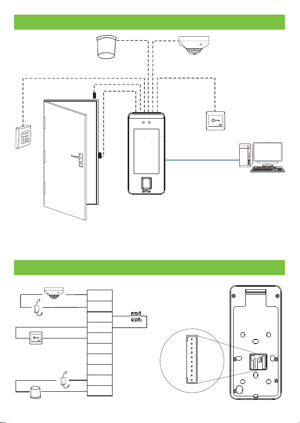
Standalone Installation
Alarm
Door Sensor
Smoke
detector
Exit Button
Card
Reader
Lock
TCP/IP
ZKBioAccess
Note: In this document, we only guide you to connect some common components,
if you want more guidance on connection of SRB, external fingerprint reader and so
on, please refer to user manual document.
Door Sensor, Exit Button & Alarm Connection
Smoke detector
+
-
+
-
Exit Button
Alarm's power switch
+
Alarm
+
-
AUX
GND
Door Sensor
SEN
GND
BUT
N1O
COM
N1C
-
AL-
AL+
2
Page 4
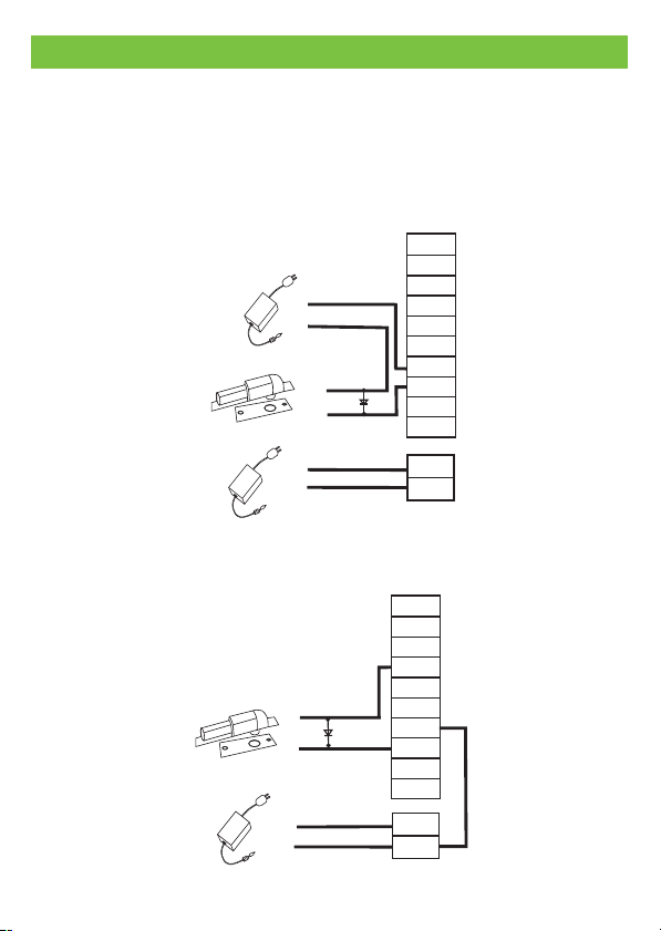
Lock Relay Connection
The system supports Normally Opened Lock and Normally Closed Lock.
The NO LOCK (normally opened at power on) is connected with 'NO1' and
'COM' terminals, and the NC LOCK (normally closed at power on) is connected
with 'NC1' and 'COM' terminals. T NC Lock below:ake as an example
1) Device not sharing power with the lock
AUX
GND
+
-
DC12V
-
+
Normally Closed Lock
-
+
DC12V
2) Device sharing power with the lock
-
Normally Closed Lock
+
-
+
DC12V
F 107R
+
F 107R
-
3
SEN
GND
BUT
N1O
COM
+
N1C
AL-
-
AL+
GND
+12V
AUX
GND
SEN
GND
BUT
N1O
COM
N1C
AL-
AL+
GND
+12V
Page 5
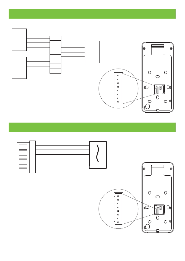
RS485 and RS232 Connection
TXD
RS232
Reader
RS485
Reader
RXD
GND
GND
485+
485-
RXD2
TXD2
GND
RXD1
TXD1
GND
485A
485B
GND
TXD
RXD
RS232
Reader
Wiegand Input Connection
+12V
GND
IDW0
IDW1
+12V
GND
WD0
WD1
Wiegand Reader
4
Page 6
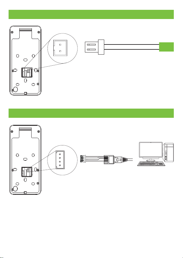
Power Connection
GND
12V
GND
12V DC
Recommended power supply
1) 12V ± 10%, at least 00mA.30
2) To share the power with other devices, use a power supply
with higher current ratings.
Ethernet Connection
TX+
TX-
RX
RX-
Default IP address: 192.168.1.201
Subnet mask: 255.255.255.0
1
2
3
4
RJ45
5
6
7
8
Click [Settings] > [Network Settings]> [TCP/IP Settings] > [DHCP], input the IP address
and click [OK].
Note: In LAN, IP addresses of the server (PC) and the device must be in the
same network segment when connecting to ZKBioAccess software.
ZKBioAccess
IP address: 192.168.1.130
Subnet mask: 255.255.255.0
5
Page 7
Quick Start
User Registration
User Authentication
Verified
View records
User registration
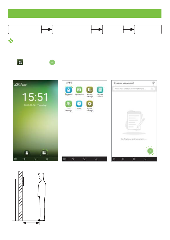
Register on the device
Click > Employee > to register new employee. Enter employee name, ID,
register fingerprint, face, badge number (ID and Mifare card are optional), and
password.
L
L
Note:
1. It's recommended to register multiple administrators.
2. It's recommend enroll user's face in 0.5med to
distance for person with1.4~1.8m height .
1.5m
14m18m.-.
L
05m.
6
Page 8
Register on the software
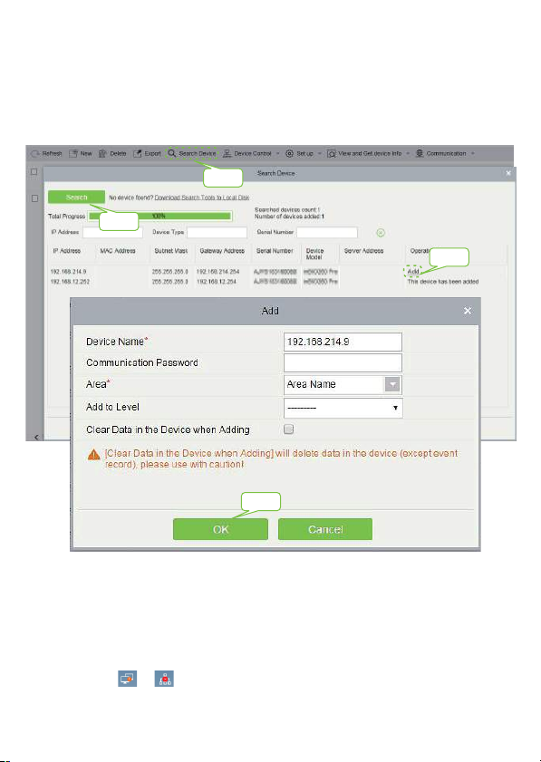
Please set the IP address and cloud service server address on the device.
1. Click [Access] > [Access Device] > [Device] > [Search Device] to add the device to
the software.
When the device has set the server address and port, it can be added automatically.
Step 1
Step 2
Step 3
Step 4
2. Click [Personnel] > [Person] > [New] to register users in the software.
3. Add users to access levels.
4. Click [Access] > [Device] > [Device Control] > [Synchronize All Data to Devices].
For more details, please refer to the ZKBioAccess User Manual.
Note: The icons or in the standby interface indicates that the network
connection or the server is abnormal. Please check the network cable and network
connection.
7
Page 9
Register on the phone
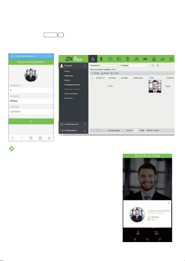
Once ZKBioAccess software installation, users could enroll face via broswer
application on their own mobile phone.
Login onto http://X.X.X.X:XX/app/v1/adreg with mobile phone browser application
Cloud server IP address
Server port
to register users.
The users will display in [Personnel] > [Temporary Personnel], click [Review].
User Authentication
Terminal could detect face in 0.3m to maximum
3m distance. The device switches to face
verification interface automatically once it detect
bright of environment change. The verification
result shows as right image.
8
Verification is successful
Page 10
View records
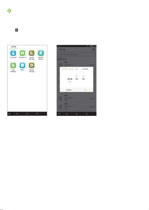
View records in the device
Click > > enter or (if user IDRecord Search Att Log Name Employee ID
field is empty, records of all users will be displayed) > select > pressTime Range
OK
Record Search Att Log Name Employee ID
Time Range
, the corresponding attendance logs will be displayed.OK
L
L
View records on the software
Click [Access] > [Report] on the software to view the records.
9
Page 11
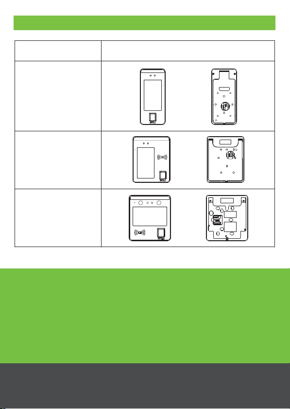
Device name
Appearance
SpeedFaceV5
SpeedFace H5
SpeedFaceT5
Appendix
www.zkteco.eu
© Copyright 2018. ZKTECO CO., LTD. ZKTeco Logo is a registered trademark of ZKTeco or a
related company. All other product and company names mentioned are used for identification
purposes only and may be the trademarks of their respective owners. All specifications are
subject to change without notice. All rights reserved.
10
 Loading...