

ZKTeco PB3030L, PB3010L, PB3010R, PB3030R, PB3060L User Manual
...
User Manual
PB3000

PB3000 User Manual
1
Contents
Chapter 1 Overview .......................................................................................................................................................................................................................... 1
1.1 Appearance and Dimensions ................................................................................................................................................................................. 1
1.2 Components inside the cabinet ........................................................................................................................................................................... 2
1.3 Working Principles.......................................................................................................................................................................................................... 3
6M( main boom 3.2m + vice boom 3m .................................................................................................................................................................. 3
Chapter 2 Product Installation ................................................................................................................................................................................................... 4
2.1 Installation Precautions ............................................................................................................................................................................................... 4
2.2 Cable Embedding .......................................................................................................................................................................................................... 4
2.3 Cabinet Installation........................................................................................................................................................................................................ 4
2.4 Boom Installation ............................................................................................................................................................................................................ 5
2.5 System Diagram .............................................................................................................................................................................................................. 7
2.6 Wiring Diagram of the Push Button Station .................................................................................................................................................. 8
Chapter 3 Troubleshoot ................................................................................................................................................................................................................. 9
Chapter 4 Optional Functions ................................................................................................................................................................................................. 10
4.1 Loop Detector ................................................................................................................................................................................................................ 10
4.2 Cooling System ............................................................................................................................................................................................................. 11
Chapter 5 Device Maintenance ............................................................................................................................................................................................. 12
Appendix Wiring Diagram ......................................................................................................................................................................................................... 13
PB3000 User Manual
1
Chapter 1 Overview
1.1 Appearance and Dimensions
PB3000 series are equipped with gray painted cabinets. PB3030 and PB3060 include main and vice boom,
PB3010 has one main boom. The dimensions are shown in the following figures.
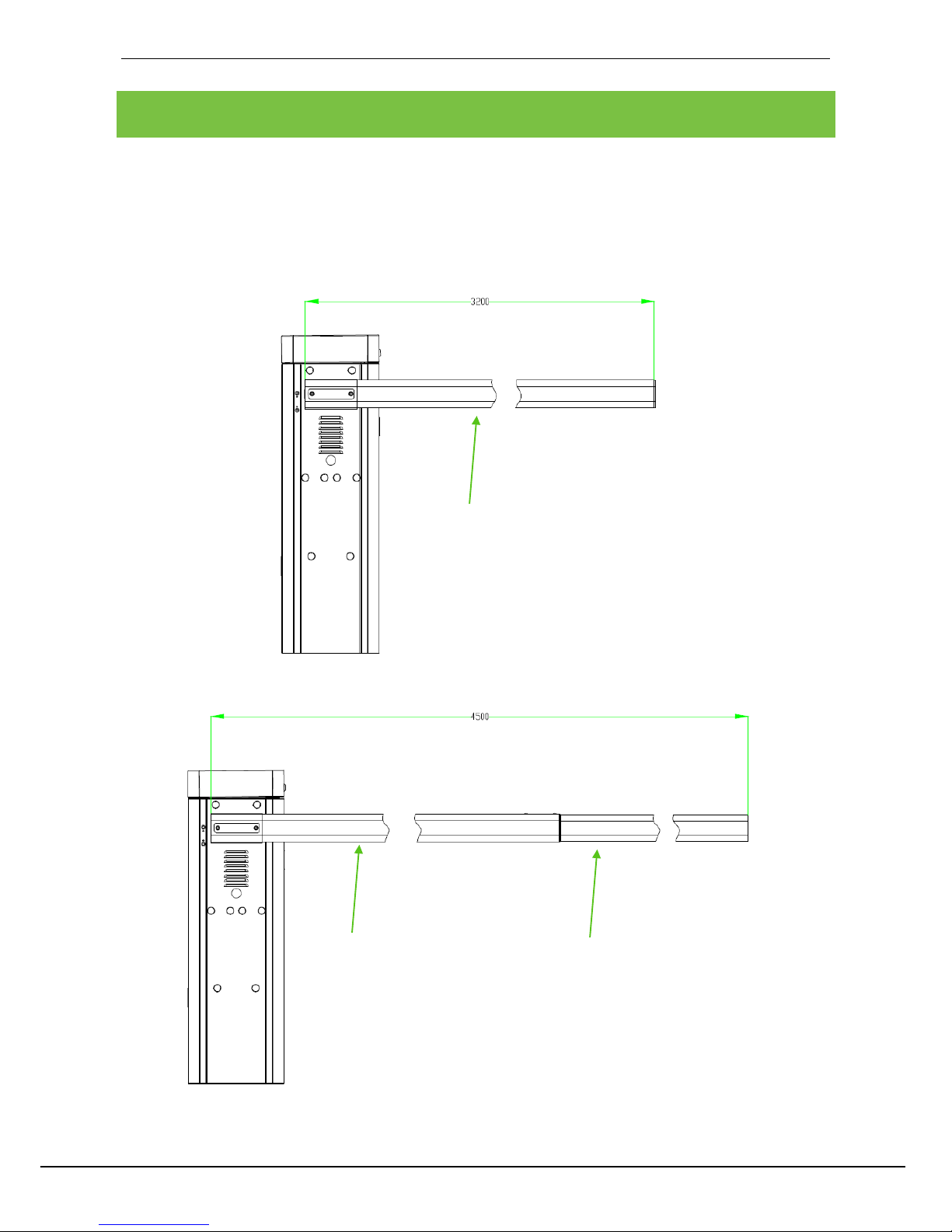
Figure 1-1 the boom length of the PB3010
Figure 1-2 the boom length of the PB3030
Main boom
Vice boom: 1500mm
Main boom

PB3000 User Manual
2
Figure 1-3 the boom length of the PB3060
1.2 Components inside the cabinet
Figure 1-4 Components inside the Chassis
Four expansion bolts
Position
sensor
Air switch
Motor
Gearbox
Handle
Main boom
Vice boom: 3000mm

PB3000 User Manual
3
1.3 Working Principles
Power subsystem: The motor and gearbox provide power for the whole system.
Speed reduction subsystem: The speed reduction system controls the lifting and falling speed of the boom.
It makes the boom slow down when the boom stops movement.
Spring balance subsystem: The compression spring provides balance for the weight of the boom to keep
the boom horizontal.
Electric control subsystem: The electric control subsystem
consists of a control board and a position sensor.
1.4 Specification Parameters of Product Series
Appearance Model Boom Type Standard Boom Length
Lifting/
Falling
Speed
Fastening
Mode
Note
Gray
appearance
series
PB3010L Straight boom 3.2 M 1.8s
Cabinet on
the left
There are 200V
and 100V types
for the device.
PB3010R Straight boom 3.2M 1.8s
Cabinet on
the right
PB3030L Straight boom
4.5M( main boom 3.2m + vice
boom 1.5m
3s
Cabinet on
the left
PB3030R Straight boom
4.5M( main boom 3.2m + vice
boom 1.5m
3s
Cabinet on
the right
PB3060L Straight boom
6M( main boom 3.2m + vice
boom 3m
6s
Cabinet on
the left
PB3060R Straight boom
6M( main boom 3.2m + vice
boom 3m
6s
Cabinet on
the right
 Loading...