

Page 1

Automatic Barrier Gate
Instructions
Version: 1.0 Date: August, 2016
Page 2

Automatic Barrier Gate Instructions
contents
Chapter 1 Overview ................................................................................................................................................ 2
1.1 Appearance and Dimensions of the Chassis ....................................................................................... 2
1.2 Appearance and Dimensions of the Boom of the Barrier Gate ......................................................... 2
1.3 Chassis Components .................................................................................................................................... 4
1.4 Working Principles .................................................................................................................................... 4
1.5 Specification Parameters of Product Series ................................................................................................. 6
Chapter 2 Product Installation ............................................................................................................................... 7
2.1 Installation Precautions ........................................................................................................................... 7
2.2 Cable Embedding ..................................................................................................................................... 7
2.2.1 Cable Embedding Procedure ...................................................................................................... 7
2.2.2 Cable Specifications ..................................................................................................................... 7
2.3 Civil Installation of the Chassis ............................................................................................................... 8
2.4 Boom Installation ...................................................................................................................................... 9
2.5 System Diagram ..................................................................................................................................... 11
Chapter 3 Device Wiring and Commissioning .................................................................................................. 13
3.1 Commissioning Preparations ................................................................................................................ 13
3.2 Commissioning Procedure .................................................................................................................... 13
3.3 Additional Functions (Optional) ................................................................................................................. 14
Chapter 4 Common FAQs ................................................................................................................................... 15
Chapter 5 Device Maintenance .......................................................................................................................... 16
5.1 Maintenance Items ................................................................................................................................. 16
5.2 Maintenance Period ............................................................................................................................... 16
Appendix 1 Packaging List .................................................................................................................................. 17
Appendix 2 Wiring Diagram of the Control Board ............................................................................................ 18
Page 3
Automatic Barrier Gate Instructions
3 m (boom length, which can be extended to 3.8 m)
4 m (boom length, which can be extended to 4.8 m)
Chapter 1 Overview
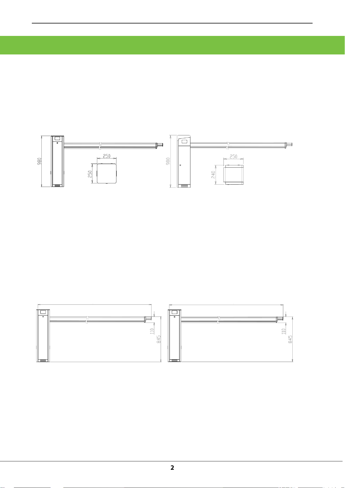
1.1 Appearance and Dimensions of the Chassis
PB1000 and PB2000 series barrier gates are available currently. The chassis appearance of the two
series differs greatly, where PB1000 series use the gray painted housing while PB2000 series use the
stainless steel housing. Figure 1-1A shows the appearance and dimensions of the PB1030 chassis
and Figure 1-1B shows the appearance and dimensions of the PB2030 chassis.
Figure 1-1A Dimensions of the PB1030 Chassis Figure 1-1B Dimensions of the PB2030 Chassis
1.2 Appearance and Dimensions of the Boom of the Barrier Gate
The PB1000 and PB2000 series chassis can be used in combination with different types of Straight
booms, Figures 1-2A, 1-2B, 1-2C show the appearance and dimensions of different types of booms.
3m Straight Boom: 4m Straight Boom:
Figure 1-2A Figure 1-2B
Page 4

Figure 1-2C
5 m (boom length, which can be extended to 5.8 m)
5m Straight Boom:
Automatic Barrier Gate Instructions
Page 5
Automatic Barrier Gate Instructions
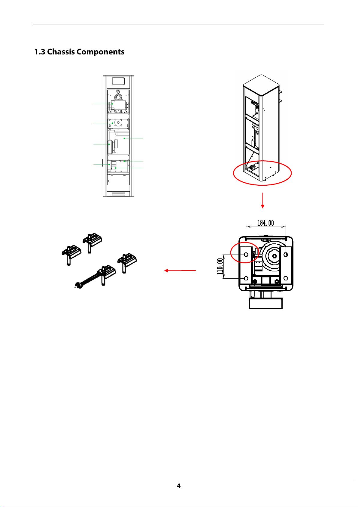
Loop Detector
(optional)
Speed reducer
Controller
ZKTeco 12 V power
supply (optional)
Motor
Air switch
Bottom amplification
Four expansion
bolts
Motor
Motor crank
Air switch
Figure 1-3 Components inside the Chassis
1.4 Working Principles
The core of the barrier gate adopts the modular design and consists of five modules: bearing and
precision platform, power subsystem (motor), sine speed reduction subsystem, compression
spring-type moment balance subsystem, and electric control subsystem.
① Platform: The barrier gate uses an independent bearing and precision platform, which is made of
rectangular steel with dimensions of 150 mm (L) x 50 mm (W) x 4-5 mm (T). Different installation
holes are precisely processed using a numerical control machine on this platform. Other
subsystems are installed around this platform and their precisions are controlled by this platform.
The function of this platform is equivalent to the frame of a car.
② Power subsystem: One motor and a matched speed reducer compose the power subsystem,
which is installed on the bearing and precision platform. Speed reducers with different reduction
ratios can be replaced to change the output moment and rotation speed of the core.
Page 6

Automatic Barrier Gate Instructions
③ Sine speed reduction subsystem: The sine speed reduction subsystem is composed of
constant-speed wheels and variable-speed wheels. It controls the falling speed of the boom. The
speed is the lowest at the lifting start point and falling start point, and highest at the angle of 45
degrees.
④ Compression spring-type moment balance subsystem: One cam, one compression spring,
and one guide groove compose the compression spring-type moment balance subsystem. It can
greatly relieve the pressure of motor output and prolong the service life of the motor.
⑤ Electric control subsystem: The electric control subsystem consists of two position detection
elements. The bearing and precision platform is processed using a numerical control machine, and
therefore, the locations of the two position detection elements can be highly associated with the
height of the sine speed reduction subsystem.
Page 7
Automatic Barrier Gate Instructions
Appearance
Model
Boom Type
Standard Boom Length
Lifting/
Falling
Speed
Fastening
Mode
Note
Gray
appearance
series
PB1012L
Straight
boom
3 m(the expansion boom
can be extended to 3.8 m)
1s
Chassis on
the left
The 3M standard
configuration is
not installed the
expansion boom.
The standard
configuration in
China uses 220 V
power input and
national
standard-complia
nt plug.
For orders placed
outside China,
specify whether
the voltage is 110
V or 220 V as well
as the plug
specifications.
The following
functions are
optional for the
12 models
above:
1.Cooling system
2.Heater system
3.Boom
illuminator
system
4.Bumping
bounce back
system
PB1012R
Straight
boom
3 m(the expansion boom
can be extended to 3.8 m)
1s
Chassis on
the right
PB1030L
Straight
boom
4 m(the expansion boom
can be extended to 4.8 m)
3s
Chassis on
the left
PB1030R
Straight
boom
4 m(the expansion boom
can be extended to 4.8 m)
3s
Chassis on
the right
PB1060L
Straight
boom
5 m(the expansion boom
can be extended to 5.8 m)
6s
Chassis on
the left
PB1060R
Straight
boom
5 m(the expansion boom
can be extended to 5.8 m)
6s
Chassis on
the right
Stainless
steel silvery
appearance
series
PB2012L
Straight
boom
3 m(the expansion boom
can be extended to 3.8 m)
1s
Chassis on
the left
PB2012R
Straight
boom
3 m(the expansion boom
can be extended to 3.8 m)
1s
Chassis on
the right
PB2030L
Straight
boom
4 m(the expansion boom
can be extended to 4.8 m)
3s
Chassis on
the left
PB2030R
Straight
boom
4 m(the expansion boom
can be extended to 4.8 m)
3s
Chassis on
the right
PB2060L
Straight
boom
5 m(the expansion boom
can be extended to 5.8 m)
6s
Chassis on
the left
PB2060R
Straight
boom
5 m(the expansion boom
can be extended to 5.8 m)
6s
Chassis on
the right
Page 8

Automatic Barrier Gate Instructions
Chapter 2 Product Installation
2.1 Installation Precautions
1) Install the parking lot barrier gate on a level road. If the road level is a slope, a horizontal base
should be built. In addition, the parking lot barrier gate system needs to be correctly wired and
operated in accordance with the wiring diagram.
2) Adjust the spring based on the boom length to achieve moment balance for Automatic Barrier Gate
prior to delivery. If the boom needs to be extended or cut due to on-site conditions, the spring
strength needs to be re-adjusted to achieve balance. Otherwise, the motor will become very hot
and the reduction gearbox will wear out excessively.
3) Do not remove and insert the wiring terminal when the device is not powered OFF. Otherwise, the
barrier gate or system will be damaged easily.
4) Pay attention to wiring specifications of relevant terminals. Do not expose excess length of the
metal part. Otherwise, short circuits or other faults may easily occur on the barrier gate during
operation.
2.2 Cable Embedding
2.2.1 Cable Embedding Procedure
1. Route cables to be connected through protective sleeves in advance.
2. Use a tool to open a cable tray on the ground.
2.2.2 Cable Specifications
Protective sleeve: φ25, black
Cable: Standard power wire, RVV3*1.0
Page 9

Automatic Barrier Gate Instructions
The power wire is
wrapped and protected
using the wire sleeve
when laid out under
the ground (the strong
current should be
separated from the
weak current)
Control
room
Screw pad
Ground
Ground
Chassis
Expansion bolt
4-MQ2
Base concrete
Standard power wire
RVV3*1.0
2.3 Civil Installation of the Chassis
Chassis Installation Procedure
1) Use positioning soft tapes to mark the installation position of the chassis, as shown in Figure 2-3A.
2) Drive four expansion bolts into the positioning soft tapes, as shown in Figure 2-3B.
3) Remove the access door and install the barrier gate, as shown in Figure 2-3C.
4) Install pads and use a wrench to tighten nuts, as shown in Figure 2-3D.
5) Install the access door, as shown in Figure 2-3E.
Figure 2-3A Figure 2-3B
Page 10

Figure 2-4A Applying Glue Figure 2-4B Wiping Off Spilled Glue
Screw pad
Ground Ground
Base
concrete
Chassis
Expansion bolt
Apply glue
Wiping Off Spilled Glue
Figure 2-3C Figure 2-3D Figure 2-3E
2.4 Boom Installation
Automatic Barrier Gate Instructions
Boom Installation Procedure
1) Take out booms.
2) Apply glue to the protrusion side of the convex boom and insert the protrusion side into the concave
boom to bond the two booms to become one boom, as shown in Figure 2-4A.
3) Wipe off spilled glue with cloth, as shown in Figure 2-4B.
4) Put the expansion boom into the main boom, adjust the length of the expansion boom, and fasten
the expansion boom with screws, as shown in Figure 2-4C.
5) Install decorative cap A on the expansion boom, fasten the decorative cap to the fixed plate of the
expansion boom, and then install decorative cap B to the end of the expansion boom, as shown in
Figure 2-4D.
6) Install the complete boom to the chassis, as shown in Figure 2-4F
Page 11

Automatic Barrier Gate Instructions
Main boom
Main boom
调整距离
Adjust the distance
Fasten screws after
adjusting the expansion
boom
Decorative cap A
Decorative
cap B
Screw
Anti-crash strip
Decorative cap A
Decorative cap B
Expansion boom
Plastic decorative cap
Barrier gate gasket
Screw
Boom
Figure 2-4C Installing the Decorative Cap
Figure 2-4C Figure 2-4D
Figure 2-4E Appearance of the Straight Boom
Page 12

Figure 2-4F Installing the Boom to the Chassis
2.5 System Diagram
Automatic Barrier Gate Instructions
Installation Diagram for the Barrier Gate and Wall:
The distance between the chassis and the wall should be greater than or equal to 100 mm.
The distance between the boom and the wall should be greater than or equal to 100 mm.
Page 13

System Diagram
Standard power wire
RVV3*1.0
Control
room
Automatic Barrier Gate Instructions
Page 14

Automatic Barrier Gate Instructions
Adjust
position A
Adjust
position B
Adjust
position C
Chapter 3 Device Wiring and Commissioning
3.1 Commissioning Preparations
1) Internal cables have been laid out completely prior to device delivery. Users are not allowed to
change the cable layout but connect the device to a 220V/110 power supply.
2) The chassis housing must be grounded and a leakage circuit breaker must be installed on the
power side.
3) Confirm that there is no object or person in the position into which the boom will fall.
4) The boom length and balance spring are adjusted to the balance state prior to product delivery. Do
not increase or decrease the length and weight of the boom, to prevent imbalance. If the length and
weight of the boom need to be changed, only professional personnel are allowed to perform the
operation.
3.2 Commissioning Procedure
1) If the boom fails to fall into a level position, adjust position A; if the boom fails to be lifted upright,
adjust position B. Properly adjust the levelness of the falling boom and the verticality of the lifted
boom. See Figure 3-2A.
2) If the boom shakes during falling or lifting, adjust position C. The shaking that occurs during lifting is
caused by the overlarge spring force. In this case, loosen the screws for several coils. If the boom
shakes during falling, tighten the screws for several coils to reach the optimal state. See Figure 3-2B.
Figure 3-2A Adjusting Levelness Verticality Figure 3-2B Adjusting the Boom in the
of the Boom Case of Shaking
3) The barrier gate provides multiple interfaces, which can be connected to the vehicle detector (Loop
Detector) and boom light bar. The barrier gate not only meets security requirements but also
supports automatic management after it is connected to a charging system (optional).
Page 15

Automatic Barrier Gate Instructions
地感
Crank
Temperature control board
(placed inside the box)
Fan
12 V power
Loop Detector
4) Use the motor crank to lift the boom in the case of a power failure.
1)Cooling system: Add the following accessories: fan, temperature control board, power module
2)Heater system, Add the following accessories: Heating device,Temperature control board,Power
module
3)Anti-crash function, Add the following accessories: Bumping bounce back system
4)Vehicle detector, Add the following accessories: Loop Detector
5)Lamp control, Add the following accessories: Boom illuminator system; Power module
Page 16

Automatic Barrier Gate Instructions
Chapter 4 Common FAQs
Q: After the boom is installed, the boom does not give any response when a remote controller
or external controller is used to control the boom lifting and falling.
A: The signal problem occurring on the grating makes the mechanism get jammed. Check whether the
grating plug malfunctions, use a controller to control the lifting and falling of the boom. If the boom can
be lifted and fall normally, the grating functions properly.
If the grating plug functions properly but the problem recurs after the motor crank is rotated, the grating
is faulty. Replace the grating.
Q: The chassis vibrates or shakes.
A: Open the chassis door, and use a wrench to tighten expansion bolts.
Q: The boom does not give a response. What are the possible causes?
A: 1) Check whether power is supplied and whether the power voltage is within the range of rated
voltage +5%.
2) Check whether the fuse of the control box is burnt.
3) Check the line and check whether cable joints on the binding post of the control box are in good
contact.
4) Check whether the silicon controlled thyristor of the control box is damaged. If yes, replace the
control box.
Note: If the barrier gate does not operate, power off the barrier gate immediately. Otherwise,
the control box will be burnt.
Page 17

Automatic Barrier Gate Instructions
Chapter 5 Device Maintenance
5.1 Maintenance Items
1) Maintain the boom. Fix the degumming or falling part of the reflection film.
2) Tighten the cable joints and fix the contact points of the device.
3) Clear away dust from components inside the chassis.
5.2 Maintenance Period
Maintenance technicians need to maintain the barrier gate system at the following frequency:
1) Maintain the boom once every month.
2) Tighten cable joints and maintain contact points of the device once every month.
3) Clear away dust from components inside the chassis once every month.
4) Common faults occurring on the barrier gate system should be rectified by system technicians. For
faults that cannot be rectified, contact the maintenance company in a timely manner and make the
Device Maintenance Records.
Page 18

Automatic Barrier Gate Instructions
1
Barrier gate
1 pc
2
Boom
1 set
3
Transmittor
2 pc
4
Key
2 pcs
5
Instruction book
1 pc
6
White stick band for installation positioning
1 pc
7
Decorative cap for the boom
1 set
8
Hardware pack
1 set
9
M12 expansion bolt
4 pcs
10
Screw pad
4 pcs
11
M10*45 mm screw
2 pcs
12
Boom gasket
1 pc
13
M10 L-shaped wrench
1 pc
14
Glue
1 set
Appendix 1 Packaging List
Page 19

Automatic Barrier Gate Instructions
Appendix 2 Wiring Diagram of the Control Board
Attached Figure – A Control Board Diagram
The controller Match code Description: Press the K4 button on the controller, motherboard flashing
yellow light, mean in the matching state, then press and hold the remote K1/K2 switch button pairing,
when the flash a red light on the motherboard, the pairing is successful. Completing pairing can be
according to the remote control K1/K2 button, check the barrier gate operation state to detect whether
the pairing is successful.
Page 20

Automatic Barrier Gate Instructions
220V/110V input
Air switch
Motor
Grating1
Grating2
Top illuminator of the pb2000
Heater(Optional)
Relay
Bumping bounce back system
Expansion Board
(Optional)
Boom illuminator
(Optional)
Fan(Optional)
12V Power
(Optional)
Loop Detector
(optional)
Attached Figure – B1 Mains Supply and Motor Wiring Diagram
Page 21

Automatic Barrier Gate Instructions
Grating1
Grating2
Top illuminator of the pb2000
220V/110V input
Motor
Air switch
Attached Figure – B2 Mains Supply and Motor Wiring Diagram
Attached Figure – C Grating and PB2000 illuminator Wiring Diagram
Page 22

Automatic Barrier Gate Instructions
Bumping bounce back
system (optional)
Loop Detector
(optional)
Loop Detector coil (optional)
Air switch
Attached Figure – D Loop Detector Wiring Diagram
Attached Figure – E Bumping bounce back system Wiring Diagram
Page 23

Automatic Barrier Gate Instructions
220V/110V input
Air switch
12V Power
(Optional)
Expansion Board
(Optional)
Boom illuminator
(Optional)
Relay
Fan(Optional)
Heater(Optional)
Attached Figure – F Expansion Board Wiring Diagram
Page 24

Automatic Barrier Gate Instructions
Expansion Board
(Optional)
Relay
Attached Figure – G Wiring Diagram of the Combined Expansion Board and Controller
 Loading...