

ZKTeco PB1030L, PB1030R, PB1060L, PB1060R, PB2012R Instructions Manual
...
Automatic Barrier Gate
Instructions
Version: 1.0 Date: August, 2016

Automatic Barrier Gate Instructions
contents
Chapter 1 Overview ................................................................................................................................................ 2
1.1 Appearance and Dimensions of the Chassis ....................................................................................... 2
1.2 Appearance and Dimensions of the Boom of the Barrier Gate ......................................................... 2
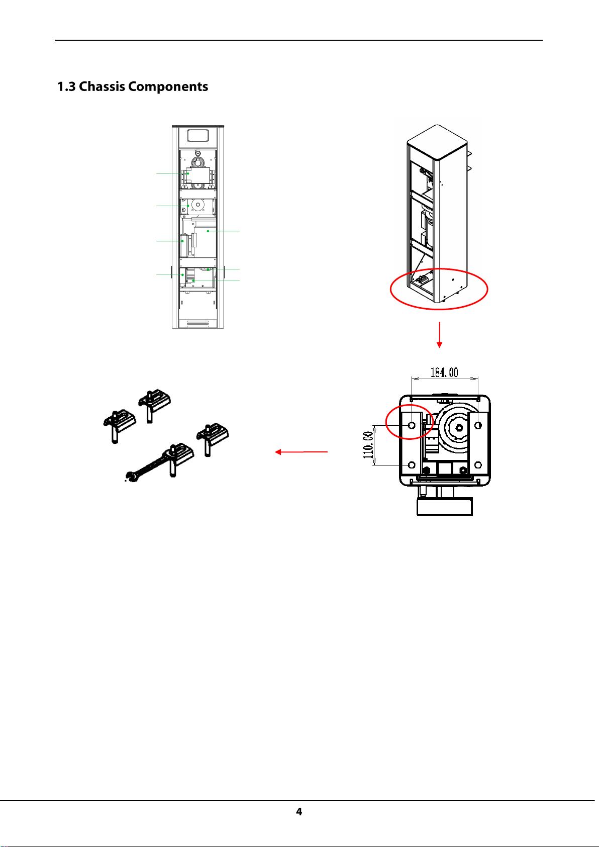
1.3 Chassis Components .................................................................................................................................... 4
1.4 Working Principles .................................................................................................................................... 4
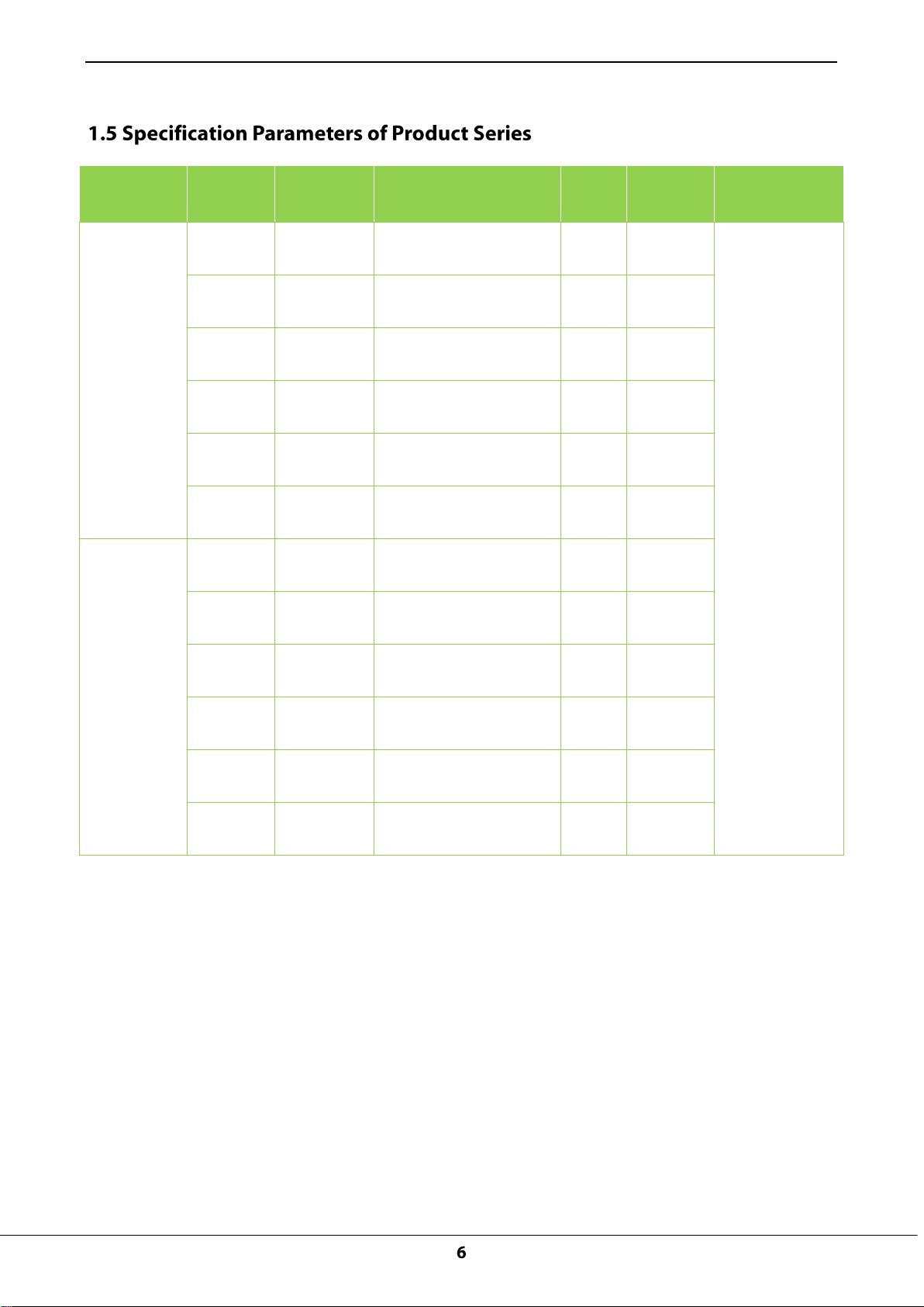
1.5 Specification Parameters of Product Series ................................................................................................. 6
Chapter 2 Product Installation ............................................................................................................................... 7
2.1 Installation Precautions ........................................................................................................................... 7
2.2 Cable Embedding ..................................................................................................................................... 7
2.2.1 Cable Embedding Procedure ...................................................................................................... 7
2.2.2 Cable Specifications ..................................................................................................................... 7
2.3 Civil Installation of the Chassis ............................................................................................................... 8
2.4 Boom Installation ...................................................................................................................................... 9
2.5 System Diagram ..................................................................................................................................... 11
Chapter 3 Device Wiring and Commissioning .................................................................................................. 13
3.1 Commissioning Preparations ................................................................................................................ 13
3.2 Commissioning Procedure .................................................................................................................... 13
3.3 Additional Functions (Optional) ................................................................................................................. 14
Chapter 4 Common FAQs ................................................................................................................................... 15
Chapter 5 Device Maintenance .......................................................................................................................... 16
5.1 Maintenance Items ................................................................................................................................. 16
5.2 Maintenance Period ............................................................................................................................... 16
Appendix 1 Packaging List .................................................................................................................................. 17
Appendix 2 Wiring Diagram of the Control Board ............................................................................................ 18
Automatic Barrier Gate Instructions
3 m (boom length, which can be extended to 3.8 m)
4 m (boom length, which can be extended to 4.8 m)
Chapter 1 Overview
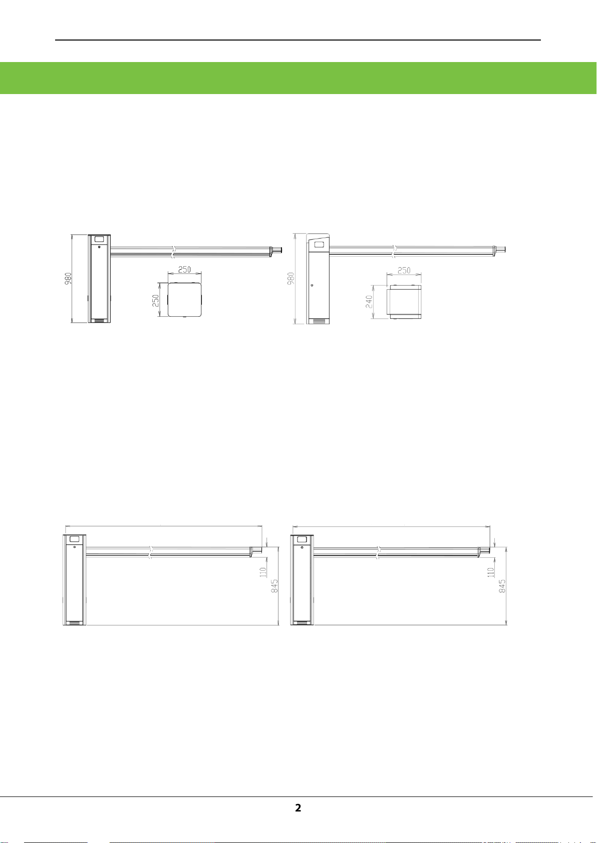
1.1 Appearance and Dimensions of the Chassis
PB1000 and PB2000 series barrier gates are available currently. The chassis appearance of the two
series differs greatly, where PB1000 series use the gray painted housing while PB2000 series use the
stainless steel housing. Figure 1-1A shows the appearance and dimensions of the PB1030 chassis
and Figure 1-1B shows the appearance and dimensions of the PB2030 chassis.
Figure 1-1A Dimensions of the PB1030 Chassis Figure 1-1B Dimensions of the PB2030 Chassis
1.2 Appearance and Dimensions of the Boom of the Barrier Gate
The PB1000 and PB2000 series chassis can be used in combination with different types of Straight
booms, Figures 1-2A, 1-2B, 1-2C show the appearance and dimensions of different types of booms.
3m Straight Boom: 4m Straight Boom:
Figure 1-2A Figure 1-2B
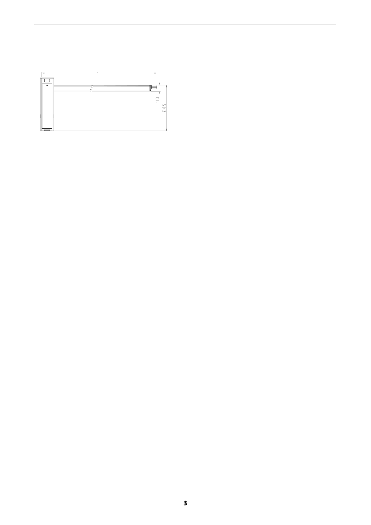
Figure 1-2C
5 m (boom length, which can be extended to 5.8 m)
5m Straight Boom:
Automatic Barrier Gate Instructions
Automatic Barrier Gate Instructions
Loop Detector
(optional)
Speed reducer
Controller
ZKTeco 12 V power
supply (optional)
Motor
Air switch
Bottom amplification
Four expansion
bolts
Motor
Motor crank
Air switch
Figure 1-3 Components inside the Chassis
1.4 Working Principles
The core of the barrier gate adopts the modular design and consists of five modules: bearing and
precision platform, power subsystem (motor), sine speed reduction subsystem, compression
spring-type moment balance subsystem, and electric control subsystem.
① Platform: The barrier gate uses an independent bearing and precision platform, which is made of
rectangular steel with dimensions of 150 mm (L) x 50 mm (W) x 4-5 mm (T). Different installation
holes are precisely processed using a numerical control machine on this platform. Other
subsystems are installed around this platform and their precisions are controlled by this platform.
The function of this platform is equivalent to the frame of a car.
② Power subsystem: One motor and a matched speed reducer compose the power subsystem,
which is installed on the bearing and precision platform. Speed reducers with different reduction
ratios can be replaced to change the output moment and rotation speed of the core.

Automatic Barrier Gate Instructions
③ Sine speed reduction subsystem: The sine speed reduction subsystem is composed of
constant-speed wheels and variable-speed wheels. It controls the falling speed of the boom. The
speed is the lowest at the lifting start point and falling start point, and highest at the angle of 45
degrees.
④ Compression spring-type moment balance subsystem: One cam, one compression spring,
and one guide groove compose the compression spring-type moment balance subsystem. It can
greatly relieve the pressure of motor output and prolong the service life of the motor.
⑤ Electric control subsystem: The electric control subsystem consists of two position detection
elements. The bearing and precision platform is processed using a numerical control machine, and
therefore, the locations of the two position detection elements can be highly associated with the
height of the sine speed reduction subsystem.
Automatic Barrier Gate Instructions
Appearance
Model
Boom Type
Standard Boom Length
Lifting/
Falling
Speed
Fastening
Mode
Note
Gray
appearance
series
PB1012L
Straight
boom
3 m(the expansion boom
can be extended to 3.8 m)
1s
Chassis on
the left
The 3M standard
configuration is
not installed the
expansion boom.
The standard
configuration in
China uses 220 V
power input and
national
standard-complia
nt plug.
For orders placed
outside China,
specify whether
the voltage is 110
V or 220 V as well
as the plug
specifications.
The following
functions are
optional for the
12 models
above:
1.Cooling system
2.Heater system
3.Boom
illuminator
system
4.Bumping
bounce back
system
PB1012R
Straight
boom
3 m(the expansion boom
can be extended to 3.8 m)
1s
Chassis on
the right
PB1030L
Straight
boom
4 m(the expansion boom
can be extended to 4.8 m)
3s
Chassis on
the left
PB1030R
Straight
boom
4 m(the expansion boom
can be extended to 4.8 m)
3s
Chassis on
the right
PB1060L
Straight
boom
5 m(the expansion boom
can be extended to 5.8 m)
6s
Chassis on
the left
PB1060R
Straight
boom
5 m(the expansion boom
can be extended to 5.8 m)
6s
Chassis on
the right
Stainless
steel silvery
appearance
series
PB2012L
Straight
boom
3 m(the expansion boom
can be extended to 3.8 m)
1s
Chassis on
the left
PB2012R
Straight
boom
3 m(the expansion boom
can be extended to 3.8 m)
1s
Chassis on
the right
PB2030L
Straight
boom
4 m(the expansion boom
can be extended to 4.8 m)
3s
Chassis on
the left
PB2030R
Straight
boom
4 m(the expansion boom
can be extended to 4.8 m)
3s
Chassis on
the right
PB2060L
Straight
boom
5 m(the expansion boom
can be extended to 5.8 m)
6s
Chassis on
the left
PB2060R
Straight
boom
5 m(the expansion boom
can be extended to 5.8 m)
6s
Chassis on
the right

Automatic Barrier Gate Instructions
Chapter 2 Product Installation
2.1 Installation Precautions
1) Install the parking lot barrier gate on a level road. If the road level is a slope, a horizontal base
should be built. In addition, the parking lot barrier gate system needs to be correctly wired and
operated in accordance with the wiring diagram.
2) Adjust the spring based on the boom length to achieve moment balance for Automatic Barrier Gate
prior to delivery. If the boom needs to be extended or cut due to on-site conditions, the spring
strength needs to be re-adjusted to achieve balance. Otherwise, the motor will become very hot
and the reduction gearbox will wear out excessively.
3) Do not remove and insert the wiring terminal when the device is not powered OFF. Otherwise, the
barrier gate or system will be damaged easily.
4) Pay attention to wiring specifications of relevant terminals. Do not expose excess length of the
metal part. Otherwise, short circuits or other faults may easily occur on the barrier gate during
operation.
2.2 Cable Embedding
2.2.1 Cable Embedding Procedure
1. Route cables to be connected through protective sleeves in advance.
2. Use a tool to open a cable tray on the ground.
2.2.2 Cable Specifications
Protective sleeve: φ25, black
Cable: Standard power wire, RVV3*1.0
 Loading...