

ZKTeco LPRS2000 User Manual

USER MANUAL
Hybrid Vehicle Recognition Terminal ---LPRS2000
Version: 1.2 Date: August, 2018
Page | 1

Safety Precautions
Electrical safety
Install the camera , reader and LED screen first, and then connect the data cable and power cable in
sequence.
Before connecting an external cable to the device, complete grounding properly and set up surge
protection; otherwise, static electricity will damage the mainboard.
Ensure that the signal connected to the device is a weak-current (switch) signal; otherwise,
components of the device will be damaged.
Ensure that the standard voltage applicable in your country or region is used. If you are not certain
about the applicable standard voltage, please consult your local electric power company. Power
mismatch may cause short circuit or device damage.
In the case of power supply damage, return the device to the professional technical personnel or your
dealer for handling.
To avoid interference, keep the device far from generators with strong electromagnetic radiation, such
as radios, televisions, and electric generators.
Operation safety
Before powering on the device, read this document carefully.
The device hardware may be damaged by transportation and other unpredictable causes. Check
whether the device has serious damage before installation. If the device has major defects you cannot
solve, contact your dealer as soon as possible.
Do not connect or disconnect cables to/from the device when it is energized.
I

Dust, moisture, and abrupt temperature changes can affect the device's service life. You are advised
not to keep the device under such conditions.
Do not keep the device in a place that vibrates. Handle the device with care. Do not place heavy
objects on top of the device.
Do not apply rosin, alcohol, benzene, pesticides, and other volatile substances that can damage the
device enclosure. Clean the enclosure with a piece of soft cloth or a small amount of cleaning agent.
Nonprofessional personnel are not allowed to open the device cover. If you have any technical
questions regarding usage, contact certified or experienced technical personnel.
Note: (1) Complete grounding properly when connecting the power supply. The positive polarity and
negative polarity of the DC 12V power supply must be connected correctly. Reverse connection may
damage the device. Do not connect the AC 24V power supply to the DC 12V input port. Read the user
manual carefully before use, and connect wires in accordance with the positive polarity and negative
polarity shown on the device's nameplate. (2) The warranty service does not cover accidental damage
and damage caused by mis operation.
II

CONTENTS
1 Overview................................................................................................................................................................................................................. 1
1.1 About This Product .......................................................................................................................................................................... 1
1.2 Features .................................................................................................................................................................................................... 1
1.3 Appearance ........................................................................................................................................................................................... 2
1.4 Port definition ...................................................................................................................................................................................... 3
1.4.1 LPR Camera ............................................................................................................................................................................ 3
1.4.2 UHF reader ............................................................................................................................................................................. 4
1.5 System Requirements .................................................................................................................................................................... 4
2 Connection ........................................................................................................................................................................................................... 5
2.1 Connection Setup ............................................................................................................................................................................. 5
2.2 Network Settings ............................................................................................................................................................................... 5
3 Reader modifying setting via demo ..................................................................................................................................................... 7
3.1 USB Connection ................................................................................................................................................................................. 7
3.2 Software Introduction .................................................................................................................................................................... 7
4 Camera Access over a Web Browser .................................................................................................................................................... 9
4.1 Login .......................................................................................................................................................................................................... 9
4.2 Liveview ................................................................................................................................................................................................ 10
4.3 Replay ..................................................................................................................................................................................................... 11
4.4 Config ..................................................................................................................................................................................................... 12
4.4.1 Local Config ........................................................................................................................................................................ 12
4.4.2 Audio Parameter ............................................................................................................................................................. 13
III

4.4.3 Video Settings ................................................................................................................................................................... 14
4.4.4 Smart ....................................................................................................................................................................................... 21
4.4.5 Network Settings ............................................................................................................................................................ 26
4.4.6 Storage Settings .............................................................................................................................................................. 30
4.4.7 Alarm Settings .................................................................................................................................................................. 31
4.4.8 COM Setting ....................................................................................................................................................................... 33
4.4.9 System .................................................................................................................................................................................... 34
4.5 Alarm ...................................................................................................................................................................................................... 38
5 FAQ s ........................................................................................................................................................................................................................ 39
IV

1 Overview
Note: The pictures in this manual may not be exactly consistent with those of your product; the
actual product's display shall prevail.
1.1 About This Product
Adopted multiple recognition modes based on long-range RFID and license plate recognition.
LPRS2000 is a hybrid recognition vehicle management terminal and mainly composed of LPR camera
and UHF reader
The LPR camera is an IP camera based on the H.264/H.265 algorithm, integrating HD imaging, image
collection, license plate recognition, image decompression, and data storage on an embedded
intelligent platform. It automatically identifies the numbers, letters, and characters on license plates,
and outputs the identified results
And the UHF reader adopts Impinj R2000 card reader chip, and the card reader part adopts module
integrated design. It has stable card reading performance, good card reading performance
consistency, long service life, low card reading performance by external influence。
1.2 Features
(1) High-resolution image decompression
The camera supports Main Stream and Sub Stream. The resolution of Main Stream: 1920 x 1080 and
1280 x 720; the resolution of Sub Stream: 704x 576, 640 x 480 and 320x 240.
(2) Comprehensive network monitoring and transfer The camera sets up a network connection using
an RJ-45 10M/100M auto-negotiation network port. It supports TCP/IP, UDP, RTP, RTSP, RTCP, HTTP, DNS,
DDNS, DHCP, FTP, NTP, PPPOE, SMTP, UPNP, and other protocols.
Fixed vehicle capture rate and recognition accuracy are up to 100%
(3) Support vehicle without license plate (or seriously fouled license plate) vehicle
(4) Adapt to complex application environment, such as thick fog weather
LPRS2000 Hybrid Recognition Integrated Machine User Manual 1

1.3 Appearance
2 LPRS2000 Hybrid Recognition Integrated Machine User Manual
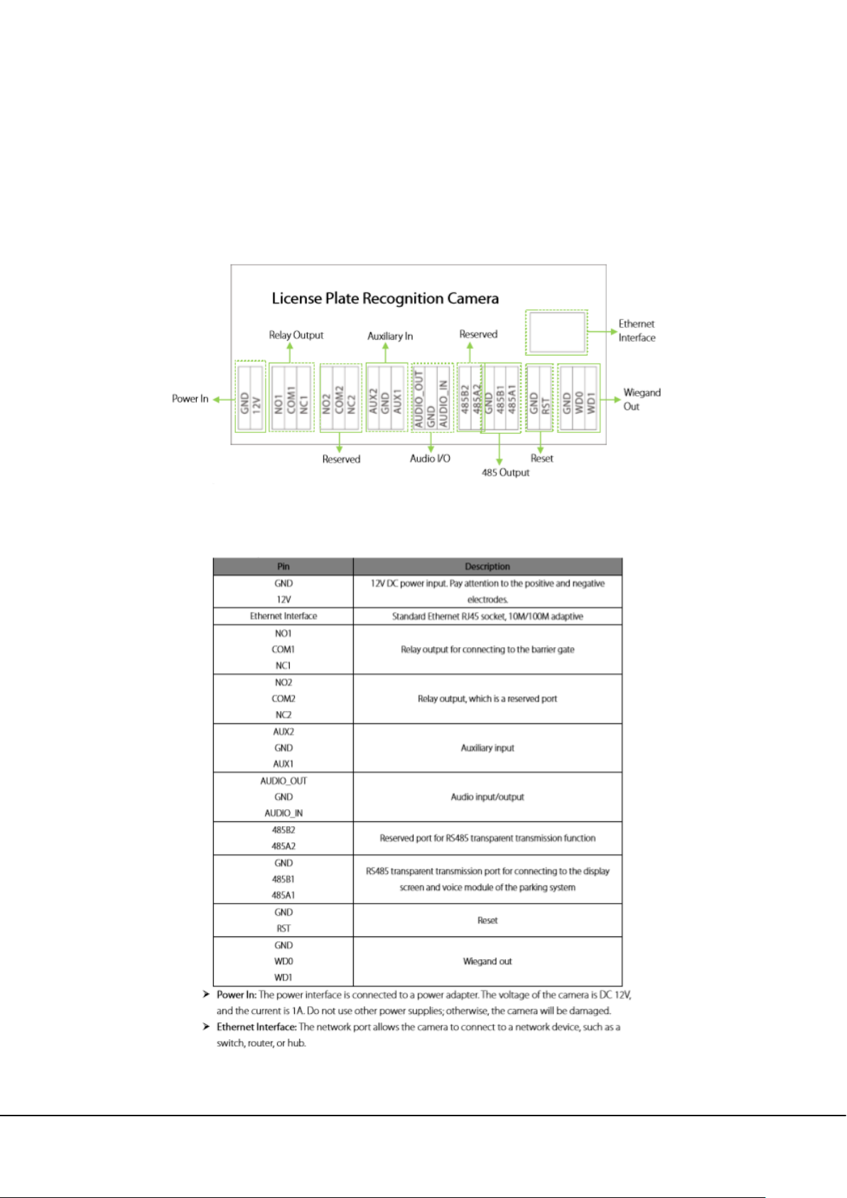
1.4 Port definition
1.4.1 LPR Camera
Wiring terminal diagram
Port description
LPRS2000 Hybrid Recognition Integrated Machine User Manual 3
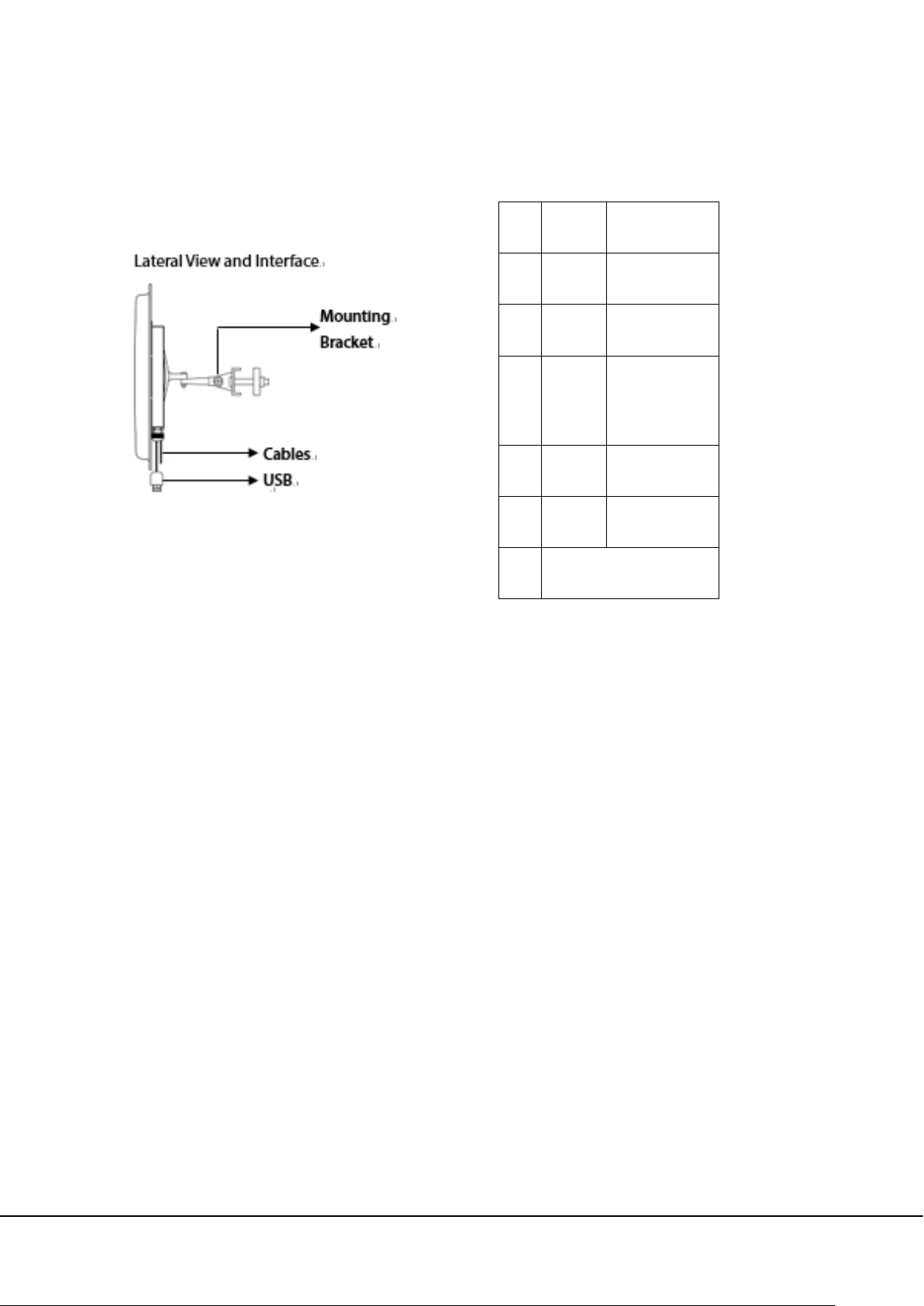
1.4.2 UHF reader
Cable Definition
NO Color Function
1 Red +12V
2 Black GND
Trigger Point
3 Purple
(Active-low)
4 Green Wiegand D0
5 White Wiegand D1
6 USB Connector
NOTE:
(1) In "Trigger Read" work mode, the reader will not read cards before a low level signal to "Trigger
Point" is delivered. "Trigger Point" is mainly used for working with the ground sensor of vehicle
parking system.
(2) In "Always Read" work mode, once the card in the effective range, the reader will output the card
number via Wiegand continually.
1.5 System Requirements
The PC used to display images and control the camera has the following requirements: CPU:
Intel Pentium 4 2.4 GHz or above.
RAM: 1G or above.
Network port: 100M Ethernet port.
Operating system: 32-bit or 64-bit operating system, such as Windows 7 ,Windows 8, Windows 10.
Internet Explorer: Microsoft Internet explorer 6.0 or later.
4 LPRS2000 Hybrid Recognition Integrated Machine User Manual
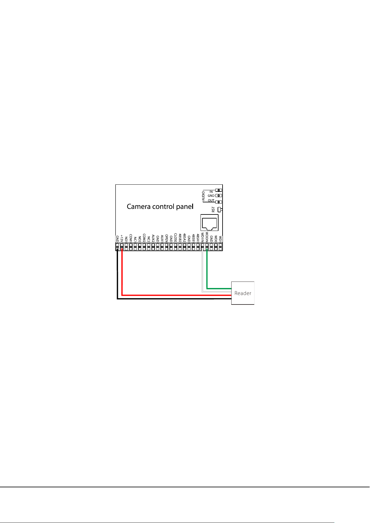
2 Connection
2.1 Connection Setup
The camera is connected to a switch or a PC over the standard Ethernet port.
The reader is connected to the camera by Wiegand.
The camera and reader are connected to a DC 12V 1A power adapter.
If the camera is connected to a central power supply, the power input polarity and the power
interface must be connected correctly.
2.2 Network Settings
Network and IP Address Configuration Set the IP address of the camera to be in the same network
segment as the PC.
Note: IP addresses in the same LAN cannot be the same; otherwise, IP address conflict will cause
device malfunction.
Default Parameter Settings Set the IP address, gateway address, and other information of the
camera properly before use. You can modify the default parameter settings according to requirements.
IP address: 192.168.1.88(Remarks: The device model is displayed on the label attached to the device
enclosure.) Subnet Mask: 255.255.255.0 Gateway: 192.168.1.1 2.2.2
Connectivity Test After you set the camera IP address, click Start > Run in the lower left corner of the
LPRS2000 Hybrid Recognition Integrated Machine User Manual 5
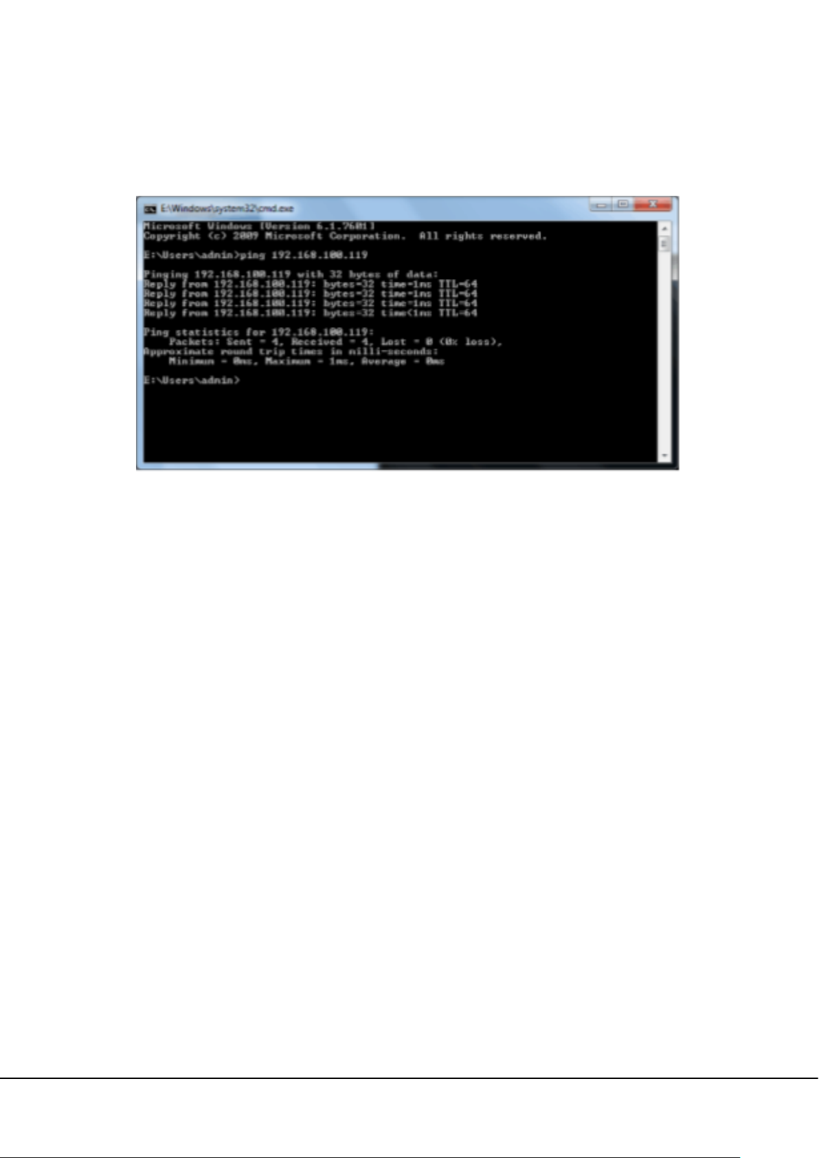
PC screen, type cmd in the Run dialog box, and type Ping+camera IP address (for example, Ping
192.168.0.18) in the command prompt window, in order to test the connectivity between the PC and
the camera.
If the message "Request timed out" or "Destination host unreachable" is returned, the PC and the
camera are not connected properly. Do the following:
(1) Check whether hardware connection is correct.
(2) Check whether the TCP/IP addresses of the PC and the camera are in the same network segment.
(3) Check whether the ping command is disabled. If you are not certain, contact your network
administrator.
6 LPRS2000 Hybrid Recognition Integrated Machine User Manual
3 Reader modifying setting via demo
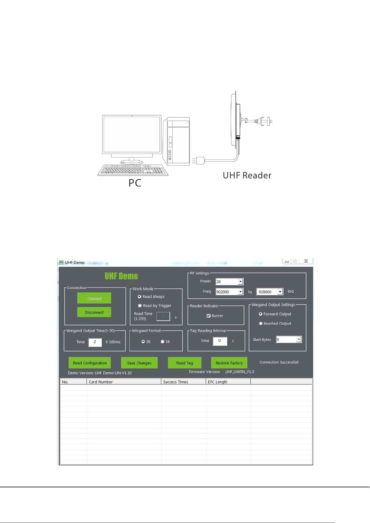
3.1 USB Connection
3.2 Software Introduction
Our company provides Demo, used to set the working parameters of the reader. Demo interface as
shown below:
LPRS2000 Hybrid Recognition Integrated Machine User Manual 7

The default configuration of the reader is as follows:
Work Mode Read Always
Communication
Interface
Output Power 33dBm
Wiegand26
Working Frequency
UHF 6E Pro: 865MHz ~ 868MHz;
Demo Using Instructions
Connect the USB port of the reader to the USB port of the computer.
The power adapter is recommended to use the DC12V/3A specification. Power supply to reader,
and the buzzer sounds once.
In the computer to open Demo, click “Connect”, on the right side of the middle will show
“Connect Successful”, and machine and demo connection success.
Wiegand Output Time: Sets the time interval between adjacent wiegand data.
Reader Indicate: Set whether the buzzer rings when the machine is on the electricity and brush
the card.
Work Mode: Set the working mode of the machine, and including always read mode, trigger
mode. Under trigger mode, time of reading card can be set when it is triggered once.
RF Setting: Set the RF parameters of the machine, including power, spectrum. Power range is
10~33dBm.
Wiegand Format: Set the machine's wiegand output format.
Wiegand Output Settings: Sets the forward or reverse output of the machine's Wiegand Data,
and start output from the first few bytes.
Tag Reading Interval: Set the machine to read the card interval. Read card interval is the time when
from the card is read within the scope of the card to the card is left out of the scope of the card to
read the second time card.
8 LPRS2000 Hybrid Recognition Integrated Machine User Manual

4 Camera Access over a Web Browser
This chapter describes how to access the camera over a web browser.
4.1 Login
Type the IP address (default: 192.168.0.88) of the camera in the address bar of a web browser. Then
input your user name and password (default: admin). The dialog box shown in the following figure is
displayed.
Control installation upon initial login:
If you access the device for the camera for the first time, you are asked to download a control. Please
manually download and install the control. The control name is WebVideoActiveXPlus.exe.
Click [File] to download the WebVideoActiveXPlus.exe control, select the downloading path and click
[Download]. After the downloading is completed, access WebVideoActiveXPlus.exe to install it. The
security prompt may be displayed during the installation. Click [Yes] to continue the installation.
Note: The WebVideoActiveXPlus.exe control must be installed for viewing videos over a web browser.
After the installation is completed, return to the Web browsing page. Log in to browse the following
video, as shown in the following figure.
LPRS2000 Hybrid Recognition Integrated Machine User Manual 9
 Loading...