

ZKTeco InBio Pro Installation Manual

INSTALLATION GUIDE
InBio Pro Series Access Control Panels
Date: June, 2016
Version: 1.2

2
What’s in the Box
InBio Pro Series Access Control Panels INSTALLATION GUIDE
4 Diode2 Screws & Anchors 2 Screwdriver

CONTENT
ContentsWhat’s in the Box ......................................................................2
Optional accessories ..............................................................4
Safety Precautions....................................................................5
Product PIN Diagram .............................................................6
LED Indicators .............................................................................7
Product Dimension .................................................................8
Installation of Panel & Cabinet ........................................9
Wiring Legend .........................................................................10
Power Wiring Diagram ..................................................... 11
Without Backup Battery ........................................................ 11
With Backup Battery ............................................................... 11
RS485 Fingerprint Reader Connection..................12
DIP Switch Setting for RS485 Reader ......................13
Wiegand Connection .........................................................14
REX Connections ...................................................................15
Lock Connection ...................................................................16
Connecting a Lock with External to Power Supply ....... 16
Switching Dry Contact to Wet Contact ............................ 17
Lock Connection ...................................................................18
Normally Open Lock Powered From Lock Terminal ...... 18
Normally Closed Lock Powered From Lock Terminal .... 18
Aux. I/O Connection ..........................................................19
Aux. Input Connection .......................................................... 19
Aux. Output Connection ....................................................... 19
Ethernet Connection .........................................................20
LAN Connection ...................................................................... 20
Direct connection ................................................................... 20
RS485 Connection ..............................................................21
RS485 Connection ..............................................................22
Restore factory setting ........................................................... 22
DIP Switch Setting ................................................................23
RS485 Address .......................................................................... 23
Terminal Resistance ................................................................23
Installation Diagram ............................................................24
Troubleshooting ....................................................................25
PC 485 Setting Table ...........................................................26
Electrical Specifications ...................................................28
Specifications ..........................................................................29
3
ZKBioSecurity
Software
InBio Pro Series Access Control Panels INSTALLATION GUIDE
4
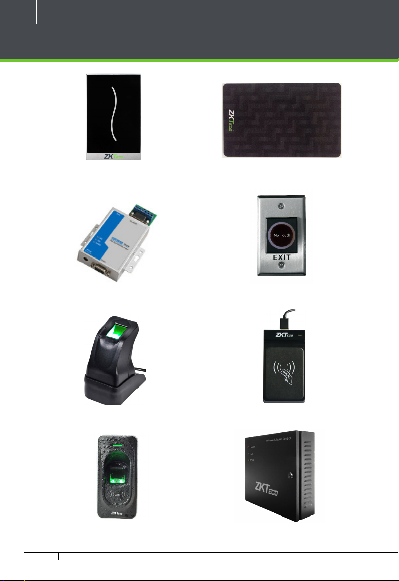
Optional accessories
Wiegand Card Reader
RS485 Convertor
ZK4500 Enrollment reader
Prox Card
K2 Exit Button
CR20E Card Enroller
RS485 Fingerprint Reader
InBio Pro Series Access Control Panels INSTALLATION GUIDE
InBio Pro Cabinet
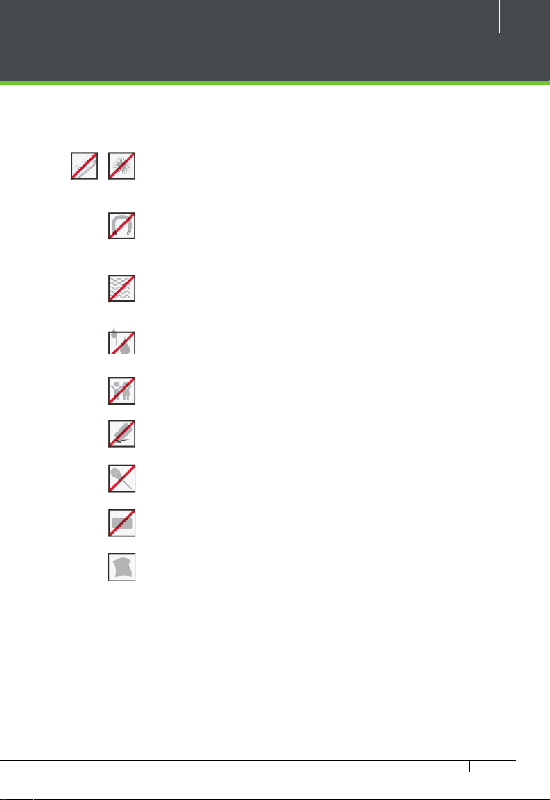
Safety Precautions
The following precautions are to keep user’s safe and prevent any damage.
Please read carefully before installation.
Do not install the device in a place subject to direct sun
light, humidity, dust or soot.
Do not place a magnet near the product. Magnetic objects
such as magnet, CRT, TV, monitor or speaker may damage
the device.
Do not place the device next to heating equipment.
Be careful not to let liquid like water, drinks or chemicals
leak inside the device.
Do not let children touch the device without supervision.
5
Do not drop or damage the device.
Do not disassemble, repair or alter the device.
Do not use the device for any other purpose than speci ed.
Clean the device often to remove dust on it. In cleaning, do
not splash water on the device but wipe it out with smooth
cloth or towel.
Contact your supplier in case of a problem.
InBio Pro Series Access Control Panels INSTALLATION GUIDE

6
Product PIN Diagram
4 Aux Inputs
Fingerprint Reader
RS485
State Indicator
#1 Door Exit Button
#1 Door Card Reader
#2 Door Exit Button
#2 Door Card Reader
#3 Door Exit Button
#3 Door Card Reader
#4 Door Exit Button
#4 Door Card Reader
SD Card Slot
LINK LED
ACT LED
Ethernet Port
InBio Pro Series Access Control Panels INSTALLATION GUIDE
DIP Switches
RS485 Communication
4 Aux Output
Figure 1
4 Lock & Door Sensor
Lock Power
InBio Pro Power
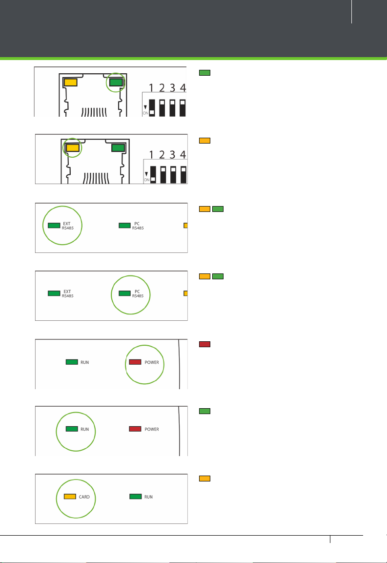
LED Indicators
Figure 2
Figure 3
Figure 4
7
LINK Solid Green LED indicates TCP/IP
communication is normal.
Flashing (ACT )Yellow LED indicates
data communication is in progress.
EXT RS485 (TX/RX) Flashing Yellow
& Green LED indicates communication is
in progress.
PC RS485 (TX/RX) Flashing Yellow
& Green LED indicates communication is
in progress.
Figure 5
Figure 6
Figure 7
Figure 8
Flashing (POWER) Red LED indicates
the panel is powered on.
Flashing (RUN) Green LED indicates
that panel is in normal working state.
Flashing (CARD) Yellow LED indicates
that the card is read by the panel.
InBio Pro Series Access Control Panels INSTALLATION GUIDE
8
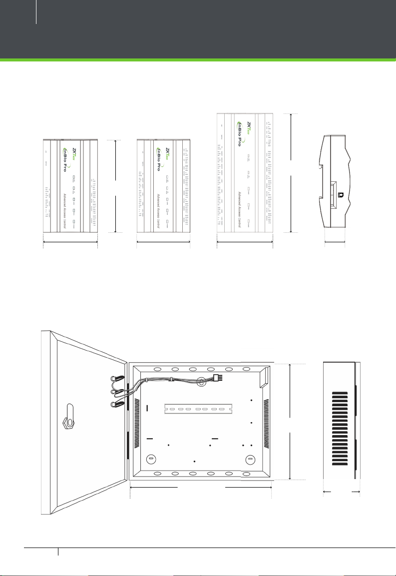
Product Dimension
InBio160Pro InBio260Pro InBio460Pro
7.125 in
(181 mm)
8.89 in
(226 mm)
4.17 in (106 mm)
4.17 in (106 mm)
4.17 in (106 mm)
Figure 9
InBio Pro- Metal Cabinet
15.7 in (400 mm)
Figure 10
13 in
(330 mm)
1.42 in (36 mm)
3.56 in
(90.5 mm)
InBio Pro Series Access Control Panels INSTALLATION GUIDE
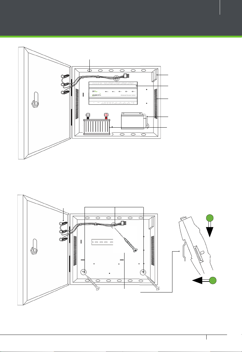
Installation of Panel & Cabinet
Cable Conduit
(Punch Hole for cables)
Figure 11
9
Temper Switch
InBio Pro Panel
Heat Dissipation Grill
Power Supply
Backup Battery
Step 1
Pass the cable through holes
We recommend drilling the mounting plate screws into solid wood (i.e. stud/beam). If a stud/beam cannot be
found, then use the supplied drywall plastic mollies (anchors).
Step 2
Mount the Metal Cabinet
Mounting HolesState Indicators Inserting Panel to Rail
Mounting Rail
Figure 12
InBio Pro Series Access Control Panels INSTALLATION GUIDE
Step 3
Insert the InBio Pro Panel as it
shown
1
2
10
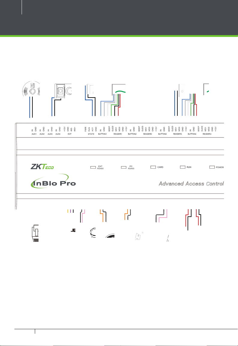
Wiring Legend
Detector
IR Sensor
Exit Button
Card Reader
Wiegand
Exit Button
Card Reader
Wiegand
Floodlight
Ethernet Cable
InBio Pro Series Access Control Panels INSTALLATION GUIDE
485 Convertor
Figure 13
Normally Open Lock
Normally Close Lock
12V DC Power
12V DC Power Supply
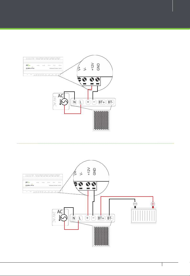
Power Wiring Diagram
Without Backup Battery
11
Ground
Figure 14
Switching Power Supply
With Backup Battery
Ground
Figure 15
Switching Power Supply
InBio Pro Series Access Control Panels INSTALLATION GUIDE
 Loading...