

ZKTeco inBIO 480 Installation And Connection Manual
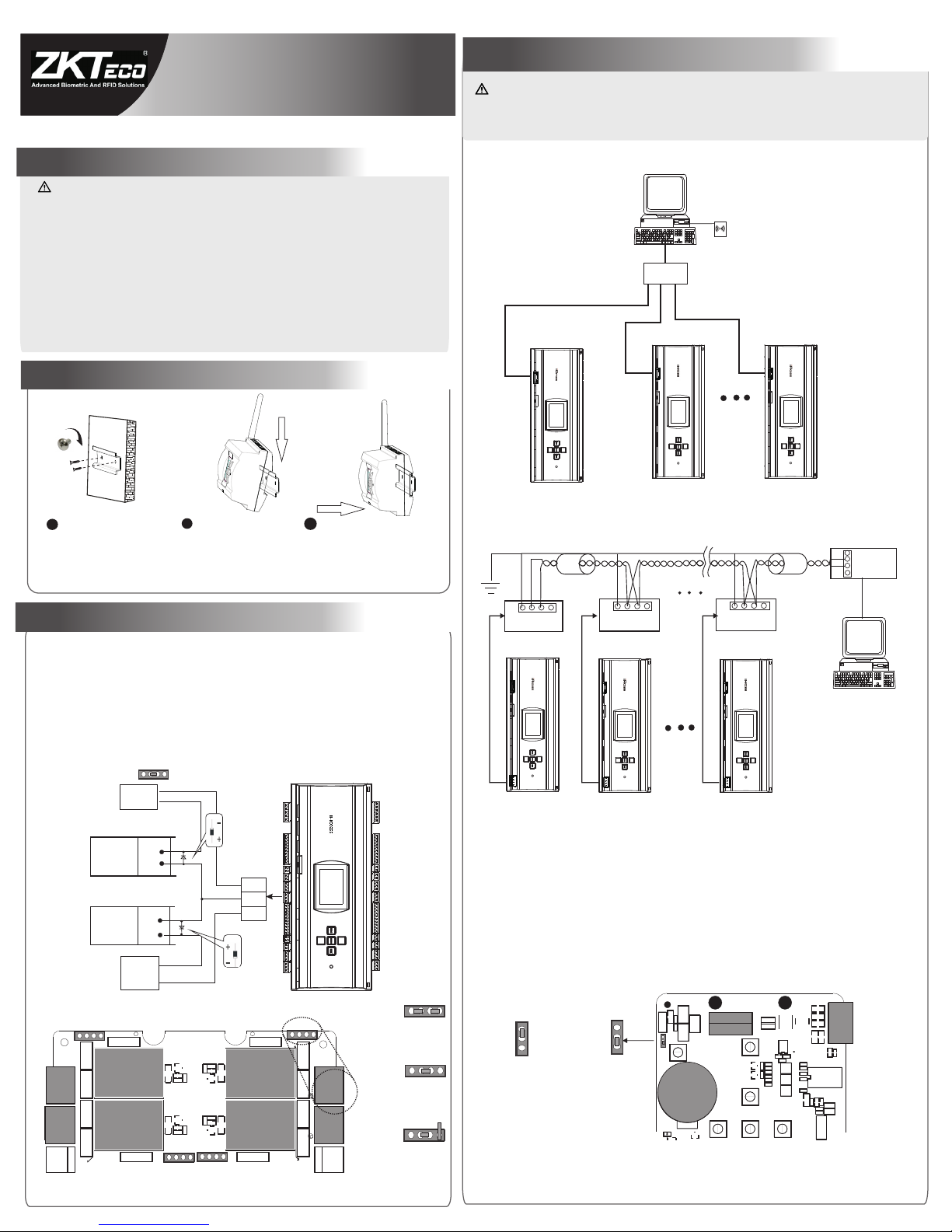
2. Installation Equipment
inBIO 480 Installation and Connection Guide
Select two of the elliptical holes on
Hang the equipment on the upper
edge of the rear iron cover, and
then press the equipment down.
Push the equipment backward to hang
the entire equipment onto the rear cover.
on the surface for fixing (Which may
be on a distribution cabinet, ceiling
or other weatherproof position).
1
2
3
1.Cautions
1)The access controller provides lock control output. For a lock which should be open when being energized and be closed
Unlock at power off
Unlock at power on
+
+
-
-
Enlar ged diag ram
NC
NO
COM
when being de-energized, the “COM” and “ NO” terminals should be used. For a lock which should be open when being
de-energized and be closed when being energized, the “COM” and “ NC” terminals should be used.
Diode
Diode
Lock
Lock
+
+
-
-
FR107
FR107
3. Lock Connection
External power supply for electronic lock
p
q
RS-485 EXT
WIEGAND 3
IN5
IN6
OUT5
OUT6
WIEGAND 4
IN7
IN8
OUT7
OUT8
1
3
1
3
1
2
1
21
10
1
3
1
3
1212
1
10
1
6
WIEGAND 1
IN1 IN2
OUT1 OUT2
WIEGAND 2
IN3
IN4 OUT3
OUT4
1
3
POWER
1
5
1
10
1 2 1 2 1
3
1
3
1
10
1 2 1 2
1
3
Reset
PC
TCP/IP Ethernet
RS485 Ports
Card Reader
1# Controller
2# Controller
n# Controller
p
q
RS-485 EXT
WIEGAND 3
IN5
IN6
OUT5
OUT6
WIEGAND 4
IN7
IN8
OUT7
OUT8
1
3
1
3
1
2
1
21
10
1
3
1
3
1212
1
10
1
6
WIEGAND 1
IN1 IN2
OUT1 OUT2
WIEGAND 2
IN3
IN4 OUT3
OUT4
1
3
POWER
1
5
1
10
1 2 1 21
3
1
3
1
10
1 2 1 2
1
3
Reset
p
q
RS-485 EXT
WIEGAND 3
IN5
IN6
OUT5
OUT6
WIEGAND 4
IN7
IN8
OUT7
OUT8
1
3
1
3
1
2
1
21
10
1
3
1
3
1212
1
10
1
6
WIEGAND 1
IN1 IN2
OUT1 OUT2
WIEGAND 2
IN3
IN4 OUT3
OUT4
1
3
POWER
1
5
1
10
1 2 1 21
3
1
3
1
10
1 2 1 2
1
3
Reset
p
q
RS-485 EXT
WIEGAND 3
IN5
IN6
OUT5
OUT6
WIEGAND 4
IN7
IN8
OUT7
OUT8
1
3
1
3
1
2
1
21
10
1
3
1
3
1212
1
10
1
6
WIEGAND 1
IN1 IN2
OUT1 OUT2
WIEGAND 2
IN3
IN4 OUT3
OUT4
1
3
POWER
1
5
1
10
1 2 1 21
3
1
3
1
10
1 2 1 2
1
3
Reset
1) TCP/IP Mode:
2) RS485 Mode:
3) Th e reco mmen ded bu s leng th of RS 485 co mmun icat ion is l ess th an 600 m eter s.
4.Equipment Communication
!
485-
485+
GND
485-4 85-
485-
485+485+
485+
GND
GND
GND
Ser ial Bus
4 3 2 1
4 3 2 1
4 3 2 1
8# Controller
2# Controller
1# Controller
p
q
RS-485 EXT
WIEGAND 3
IN5
IN6
OUT5
OUT6
WIEGAND 4
IN7
IN8
OUT7
OUT8
1
3
1
3
1
2
1
21
10
1
3
1
3
1212
1
10
1
6
WIEGAND 1
IN1 IN2
OUT1 OUT2
WIEGAND 2
IN3
IN4 OUT3
OUT4
1
3
POWER
1
5
1
10
1 2 1 21
3
1
3
1
10
1 2 1 2
1
3
Reset
p
q
RS-485 EXT
WIEGAND 3
IN5
IN6
OUT5
OUT6
WIEGAND 4
IN7
IN8
OUT7
OUT8
1
3
1
3
1
2
1
21
10
1
3
1
3
1212
1
10
1
6
WIEGAND 1
IN1 IN2
OUT1 OUT2
WIEGAND 2
IN3
IN4 OUT3
OUT4
1
3
POWER
1
5
1
10
1 2 1 21
3
1
3
1
10
1 2 1 2
1
3
Reset
p
q
RS-485 EXT
WIEGAND 3
IN5
IN6
OUT5
OUT6
WIEGAND 4
IN7
IN8
OUT7
OUT8
1
3
1
3
1
2
1
21
10
1
3
1
3
1212
1
10
1
6
WIEGAND 1
IN1 IN2
OUT1 OUT2
WIEGAND 2
IN3
IN4 OUT3
OUT4
1
3
POWER
1
5
1
10
1 2 1 21
3
1
3
1
10
1 2 1 2
1
3
Reset
Not es:
Lock Power
+
+
-
-
Lock Power
3) Ea ch rela y may wor k under t he wet mo de or dry m ode by se tting t he jump er term inal. I f the 12V po wer
1 2 3 4
sup ply ins ide the a ccess c ontro ller us es exte rnal po wer sup ply, the o utput of e ach rel ay is und er the “w et mode ”.
OUT4
Relay
Relay
Jum per ter minal s
Jum per ter minal s
wet m ode:
OUT8
OUT7
Relay
Relay
OUT3
1
1
2
2
3
3
dry m ode:
IN8
IN4
J24 E nlargement
Factory d efault
Terminal r esistance s etting
Terminal resistance setting diagram (The first layer of PCB)
11
22
33
RS485
J24
Ple ase not ice the f ollow ing cau tions . Mis-o perat ion may l ead to pe rsona l injur y or
1) D o not ene rgize t he sys tem be fore i nsta llat ion is c ompl ete. N ever c arry o ut ins tall atio n
Vision: 1.0 .1 D ate: July, 2011
2) All p erip hera l devi ces mu st be gr ound ed.
Swi tch
4) Wh en the b us is lo nger t han 30 0 m, to en hanc e the st abil ity of c ommu nica tion , it is ne cess ary
act iviti es when t he syst em is ene rgize d.
the r ear iro n cover. D rill tw o holes
2) If t he elec trica l lock is c onnec ted to th e acces s contr ol syst em, you n eed to pa ralle l one FR1 07 diod e (Equi pped
in th e packa ge) to pr event t he self -indu ctanc e EMF affe ct the sy stem, d o not rev erse th e polar ities .
If th e exter nal pow er supp ly uses p otent ial fre e conta cts, th e “dry mo de” sho uld be us ed. ple ase ref er to
Ins truct ions fo r Hardw are of C4 -200/ 400 Acce ss Cont rolle r.
* It is recommended to short 2-3 ports, the output use the “dry mode”, the electronic lock use the external power supply.
of lo ck port s
The P C softw are com munic ate wit h the sys tem thr ough tw o proto cols (R S485 an d TCP /IP)
for d ata exc hange a nd remo te mana gemen t. The co mmuni catio n cabl e sho uld be aw ay
fro m high- volta ge line s as far as p ossib le. Do no t keep th e commu nicat ion cab le in par allel
wit h power c ords or b ind the m toget her.
RS 48 5 Conve rtor
1) In terna tiona lly acc epted RV SP (shi elde d twis ted- pair ) wire s shou ld be us ed for c ommu nica tion
to RS4 85 comm unica tion wi res sho uld be co nnect ed by mea nseff ecti vely a void i nter fere nce.
of bu s casca de conn ectio n.
2) Th eore tica lly, in R S485 c ommu nica tion , one bu s may be connected with 64 access controllers.
to ch ange J2 4 on the fi rst lay er of PCB ( see the f igure b elow) i nthe fi rst and t he last u nits (s ee
uni t 8# as sho wn in the f igure a bove) t o short p ins 2-3 . This me thod is e quiva lent to c onnec t
equ ipmen t failu re:
Rel ay outp ut port s and jum per ter mina ls set ting ( The se cond l ayer o f PCB)
4 3 2 1
1 2 3 4
1 2 3 4
1 2 3 4
1 2 3 4
1 2 3 4
PC
It is r ecomm ended t o conen ct with n o more th an 16 dev ices.
wit h a resis tance o f 120 ohm .
Jump ing Termi nals
Dis tribut ion
diag ram of th e
fact ory def ault
jump er cap:
1
234
3) It i s recom mende d that al l wires r un thro ugh cas ing pip es whic h may by PV C or galv anize d
5) It i s recom mende d that ca rd read ers and b utton s shoul d be inst alled a t heigh t of 1.4m -1.5m
6) It i s recom mende d to use th e power s upply i n case fo r contr ol pane l, and ex terna l power
4) It i s stron gly rec ommen ded tha t the len gth of ex posed p art of an y conne ction c able
sho uld not b e longe r than 4 mm . avo id Pro fessi onal cl ampin g tools m ay be use d to
uni ntent ional c ontac t of expo sed wir es to avo id shor t-cir cuit or c ommun icati on fai lure .
sup ply for e ach loc k.
one s.
abo ve grou nd.
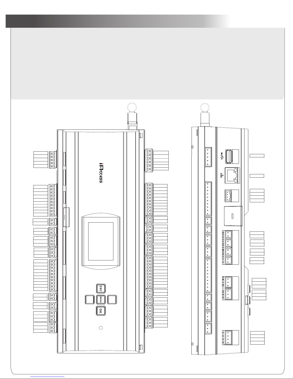
1) The auxiliary input may be connected to infrared body detectors, smoke detectors, gas detectors, window magnetic alarms, wireless exit switches, etc.
2) The auxiliary output may be connected to locks, monitors, alarms, door bells, etc.
3) The auxiliary input and the auxiliary output is set with iAccess4.0.
support for ordering machines with GPRS and WiFi functions.
A. Use 2-conducotor power cord
5) Recommend use of wires
B.
C. Use 2-conducotor lock power cord (RVV 2*0.75mm)
D. Use 2-conducotor switch or magnetic power cord (RVV 2*0.5mm)
5. Connection Terminals
Notes:
4) GP RS, WiFi a nd the f ollo wing i tems i ndic ated w ith " *" ar e opti onal . Plea se con tact o ur bus ines s repr esen tati ves or p re-s ale te chni cal
Data_Tx-
Data_Tx+
GND
Data_RxTxData_RxTx+
Shield
+12V
GND
Shield
AC Fail
Battery Fail
VCC 12V
GND
D0
D1
Shield
LED_G
LED_R
BEEP
Hold
Card_present
VCC 12V
GND
D0
D1
Shield
LED_G
LED_R
BEEP
Hold
Card_present
Card_present
Hold
BEEP
LED_R
LED_G
Shield
D1
D0
GND
VCC 12V
Card_present
Hold
BEEP
LED_R
LED_G
Shield
D1
D0
GND
VCC 12V
GND
Analog_input
GND
Analog_input
GND
Analog_input
GND
Analog_input
Analog_input
GND
Analog_input
GND
Analog_input
GND
Analog_input
GND
NO
COM
NC
NO
COM
NC
NO
COM
NC
NO
COM
NC
NC
COM
NO
NC
COM
NO
NC
COM
NO
NC
COM
NO
Lock 2
Auxiliary Output
Lock 1
Lock 3
Lock 4
Auliliary Output
Auxiliary Output
Auliliary Output
Magnet 3
Magnet 4
Magnet 3
Magnet 1
Door Switch 3
Door Switch 1
Door Switch 3
Door Switch 4
12V Power Input
Shield Wire
AC Fail Detection
Battery Fail Detection
12V Power Output
12V Power Out
12V Power Output
12V Power Output
Wiegand Input
Wiegand Input
Wiegand Input
Wiegand Input
Shield Wire
Sheild Wire
Shield Wire
Shield Wire
Green
Green
Red
Red
Red
Red
Green
Green
Beep
Beep
Beep
Beep
Controlled Reader Hold
Controlled Reader Hold
Controlled Reader Hold
Card Present
Card Present
Card Present
Card Present
{
{
{
{
{
{
{
{
{
{
{
{
{
{
{
Shield Wire
}
}
}
}
}
}
}
}
}
}
}
}
RS 422 Send
}
RS422 Receive
or RS485 Comm.
}
Controlled Reader Hold
Output
Output
Output
*
*
*
*
*
*
*
p
q
RS-485 EXT
WIEGAND 3
IN5
IN6
OUT5
OUT6
WIEGAND 4
IN7
IN8
OUT7
OUT8
1
3
1
3
1
2
1
21
10
1
3
1
3
1212
1
10
1
6
WIEGAND 1
IN1 IN2
OUT1 OUT2
WIEGAND 2
IN3
IN4 OUT3
OUT4
1
3
POWER
1
5
1
10
1 2 1 2 1
3
1
3
1
10
1 2 1 2
1
3
Reset
Front View
Front Side View
RS-232
IN9
OUT9
IN12IN11
IN10
OUT10
RS-485
1
3
1
3
1 21 21 21
2
1 4
1 4
Output
*
*
*
*
*
TXD232
RXD232
/
GND
Shield
RS 485RS 485+
GND
USB
TCP/IP
Analog_input
GND
Analog_input
GND
Analog_input
GND
Analog_input
GND
NO
COM
NC
NO
COM
NC
U Disk
TCP/IP Comm.
RS 232 Send
Auxiliary Input
Auxiliary Input
Auxiliary Input
Auxiliary Input
Auxiliary Output
Auxiliary Output
Shield Wire
RS485 Comm.
RS485 Ground
RS 232 Receive
Idle
RS 232 Ground
*
*
*
*
*
*
A
B
B
B
B
C
C
C
C
C
C
C
C
C
C
D
D
D
D
D
D
D
D
D
D
D
D
*
*
}}
Acc ordin g to the po rt you co nnect ed, cho ose suc h as 8,10 c onduc tor cor d commu nicat ion twi sted- pair se nsor ca ble (RVV P 8*0 .5mm)
 Loading...