

ZKTeco iClock 885 User Manual

iClock 885
USER MANUAL
Version 1 - December 2018

CONTENT
Contents
USER MANAGEMENT 5
1
1.1 New User ...................................................................... 6
1.2 All Users ........................................................................ 14
1.3 Single Line ..................................................................... 14
USER ROLE 16
2
COMMUNICATION 18
3
3.1Ethernet ........................................................................19
3.2 Serial Communication .......................................................19
3.3 PC Connection ................................................................ 20
3.4 Wireless Network ............................................................. 21
3.5 Cloud Server Settings ........................................................ 22
3.6 Wiegand Setup ............................................................... 24
SYSTEM 28
4
4.1 Date Time .....................................................................29
4.2 Attendance .................................................................... 29
4.3 Fingerprint ....................................................................33
4.4 Reset ...........................................................................35
4.5 USB Upgrade .................................................................. 35
PERSONALIZE 36
5
5.1 User Interface ................................................................. 37
5.2 Voice ............................................................................40
5.3 Bell Schedules ................................................................. 41
5.4 Punch State Options.........................................................45
5.5 Shortcut Key Mapping ....................................................... 46
5.6 Manual Add Log .............................................................51

CONTENT
DATA MANAGEMENT 53
6
6.1 Delete Data .................................................................... 54
6.2 Backup Data
6.3 Restore Data ...................................................................56
ACCESS CONTROL 58
7
7.1 Access Control Options ......................................................59
7.2 Time Schedule ................................................................62
7.3 Holidays ........................................................................ 62
7.4 Access Group .................................................................65
7.5 Combined Verication ......................................................68
7.6 Anti-passback Setup .........................................................69
7.7 Duress Options ............................................................... 70
USB MANAGER 72
8
8.1 Download .....................................................................73
8.2 Upload .........................................................................74
..................................................................55
8.3 Download Options ...........................................................74
ATTENDANCE SEARCH 76
9
SHORT MESSAGE 79
10
10.1 New Message ................................................................ 80
10.4 Draft Messages .............................................................. 82
10.2 Public Messages .............................................................82
10.3 Personal messages .......................................................... 82
10.5 Message Options ........................................................... 83
WORK CODE 84
11
11.1 New Work Code .............................................................85
11.2 ALL WORK CODES ........................................................... 86
11.3 SET WORK CODE ............................................................86

CONTENT
JOB CODE 88
12
12.1 New Job Code ...............................................................89
12.2 All Job Code
12.2 All Job Codes ................................................................ 93
12.3 Job Code Options
12.4 Job Group Option Menu Operation ...................................... 98
TIP CODE 101
13
13.1 Tip code settings .......................................................... 102
13.2 Tip code
AUTOTEST 107
14
14.2 Test LCD .................................................................... 108
14.1 All Test ...................................................................... 108
14.3 Test Voice ................................................................... 110
14.5 Test Fingerprint Sensor .................................................. 110
14.4 Test Keyboard ............................................................. 110
................................................................. 90
........................................................... 96
.................................................................... 103
14.6 Cam Testing ............................................................... 110
14.7 Test CLOCK RTC ............................................................ 110
SYSTEM INFORMATION 111
15
15.2 Device Info ................................................................. 112
15.1 Device Capacity ........................................................... 112
15.3 Firmware Info ............................................................. 113

1
USER MANAGEMENT
1
USER MANAGEMENT
Go to menu and select User Management .
1.1 NEW USER
Select
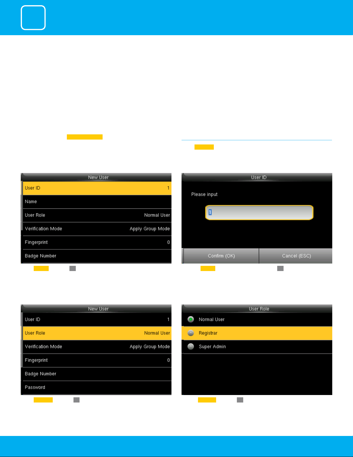
New User .
Enter the User ID by using the keypad and press OK.Select User ID and press OK.
Click on Registrar and press OK.Select User Role and press OK
6
1
USER MANAGEMENT
A user with “Registrar” is able to “Add”, “Delete” and “Edit” standard users to the
device.
He/She is also able to view “Standard Attendance Data” for existing users on
the clock.
Select Verication Mode and press OK.
Verication mode is basically used to verify the user.
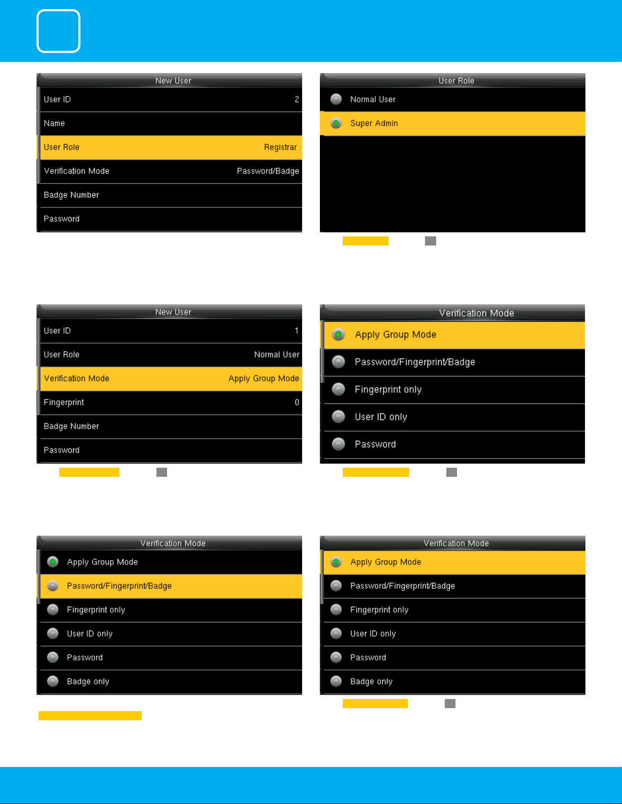
Select Super Admin and press OK.
The super administration has rights to all the menu functions.
Select Apply Group Mode and press OK. By pressing the apply group mode
the user can verify himself with all the options that are available in verication mode.
By clicking the option above the user can verify himself either with his/her
Fingerprint/Password or Badge .
Select Apply Group Mode and press OK.
7
1
USER MANAGEMENT
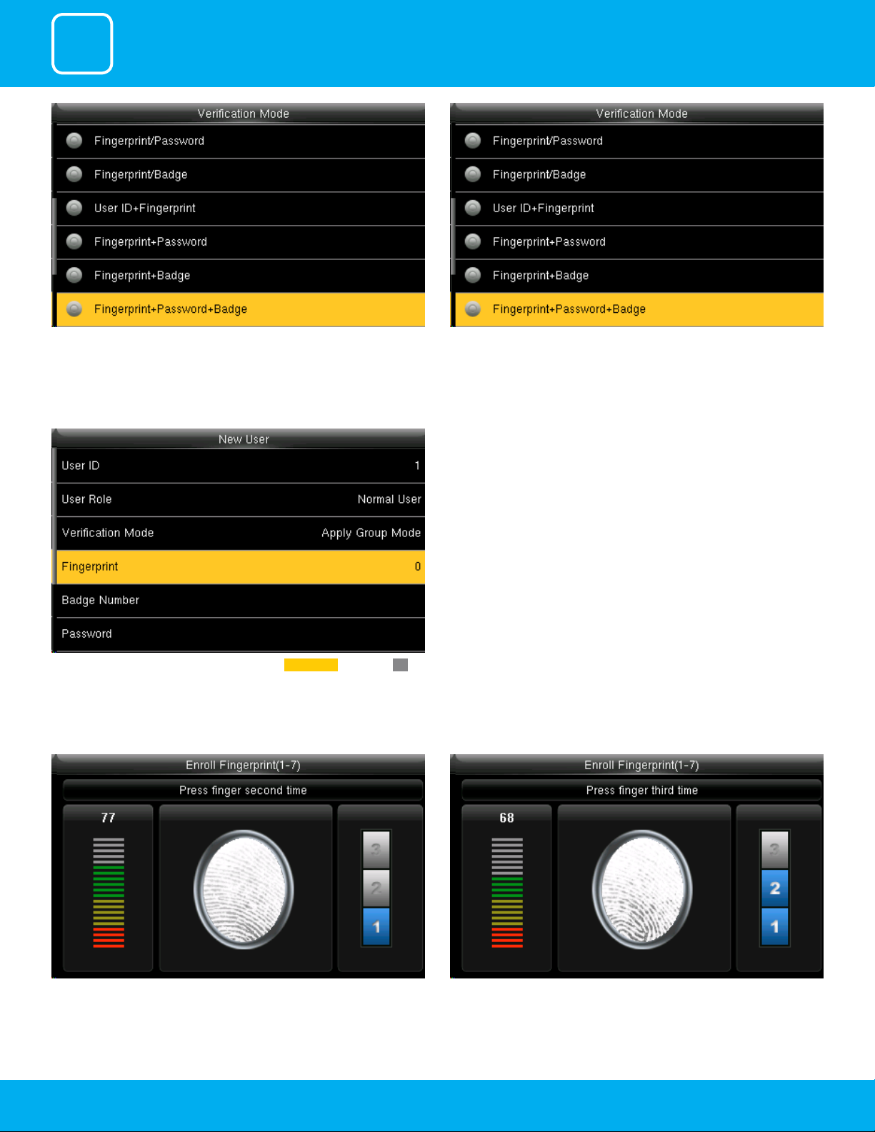
When you select the option from above the user needs all three things to
verify himself or it won’t verify.
To enroll the ngerprint for the new user select ngerprint and select OK.
When you select the option above the user needs his/her ngerprint and
either badge or user id to verify himself.
When there is a / sign you can use either of the options to verify.
Place your nger on the ngerprint sensor properly.
Place the same nger on the ngerprint sensor for the second time. After that, you can again place the same nger on the ngerprint sensor.
8
1
USER MANAGEMENT
Enrollment succeeds. If the enrollment fails, the system will display a prompt
message and return to the [Enroll Fingerprint] interface. In this case, you
need to repeat the operations of step 2
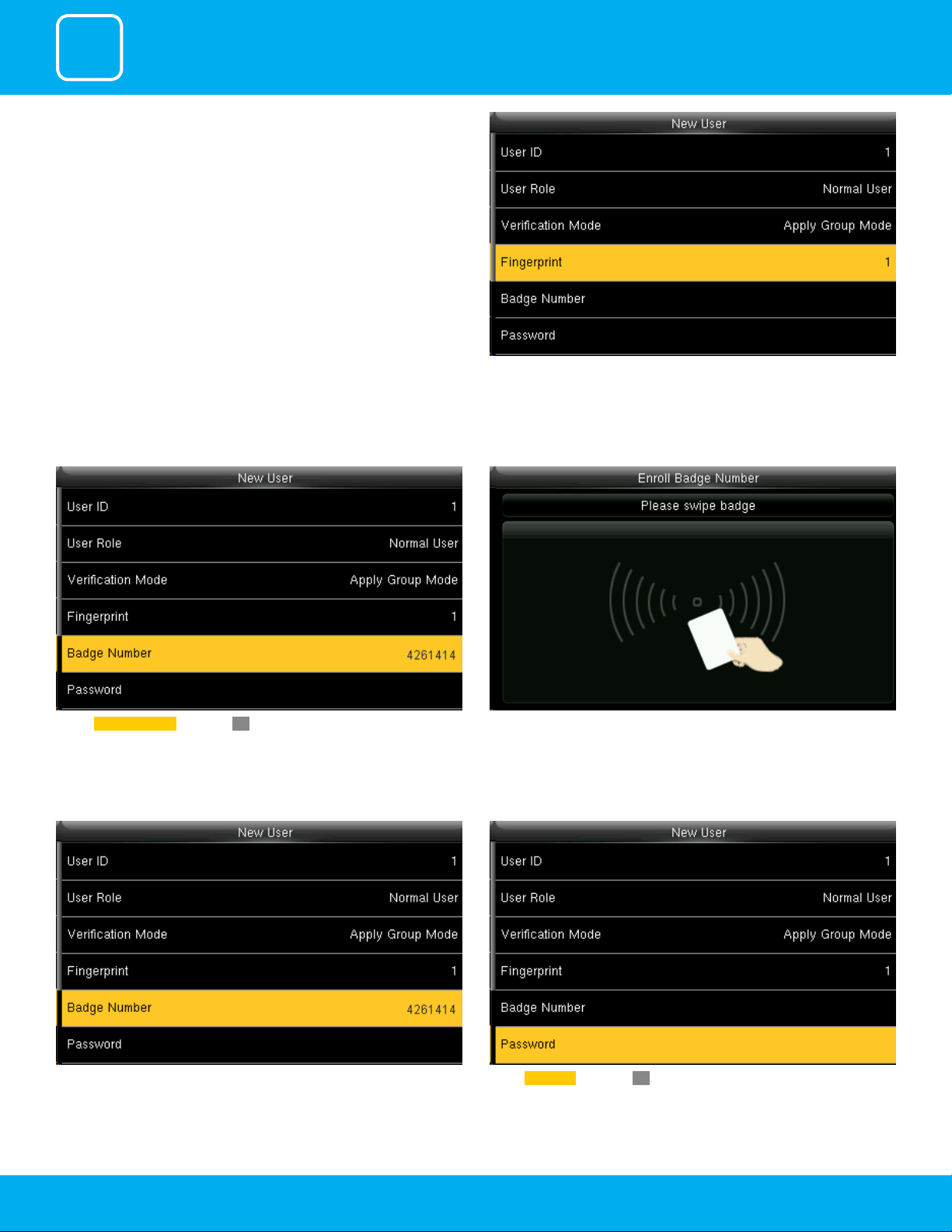
Select Badge Number and press OK.
After the ngerprint is enrolled succesfully the ngerprint will be shown as 1
as above which means one ngerprint is enrolled.
When you select the badge number it will tell you to swipe the badge/rd
card to enroll.
When you swipe the badge number the badge number will be displayed as
above.
Here I swiped badge number 4261414 and that number is enrolled for that
user.
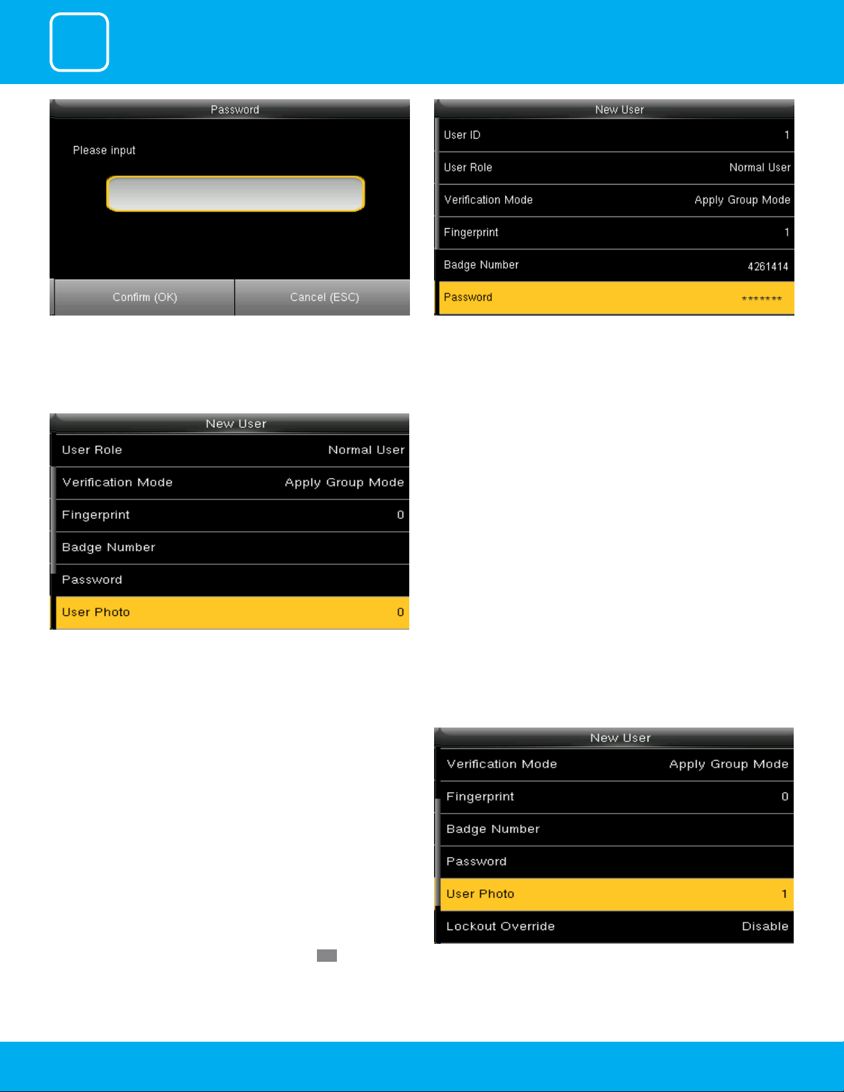
Select Password and press OK.
9
1
USER MANAGEMENT
Here you can input the password by using the keypad to enroll. Once you entered the password, the above image will be displayed for
that user with his/her ngerprint, the badge number and password that is
needed for him/her to enter.
Select “User Photo” and press “OK”. Here you can see in the user photo it is 0
means the user has not register him or herself.
Once the camera gets the clear picture of the user select OK from the keypad and green tick mark will appear which means the camera has successfully register him or herself..”
When the above window pop up the user can stad in front of camera to get
register.
Once the user registers themselves the user photo will display 1 which
means photo of that particular user has been register successfully.
10
1
USER MANAGEMENT
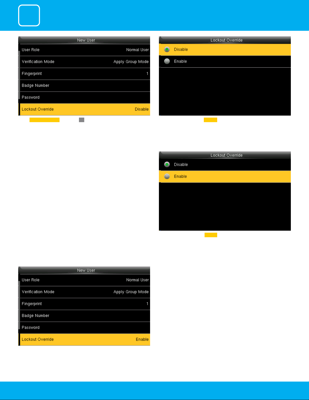
Select Lockout Override and select OK Select lockout override as Disable .
A user punches in o the activate schedules, the device will notify the user
by “Error! Invalid time period Failed to verify.”
When you enable this function the above image will be displayed. A user punches in o the activate schedules, the device will notify the use by
Select lockout override as Enable .
“Successfully Veried.” as shown below
11
1
USER MANAGEMENT
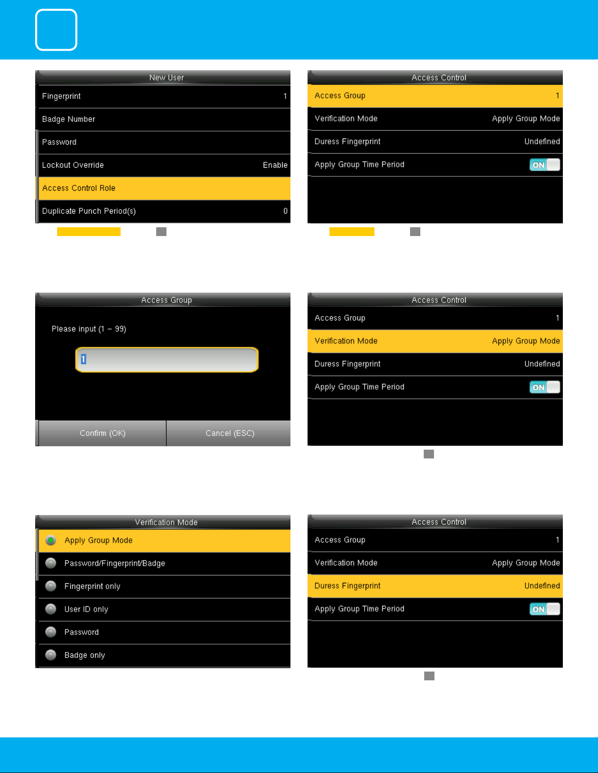
Select Access Control Role and press OK.
You can change the number for that group in the input section above using
the keypad.
Select Access Group and press OK.
Select verication mode and press OK
In verication mode, you can select apply group mode which will select all
the methods of verication as shown above.
Select duress ngerprint and press OK.
12
1
USER MANAGEMENT
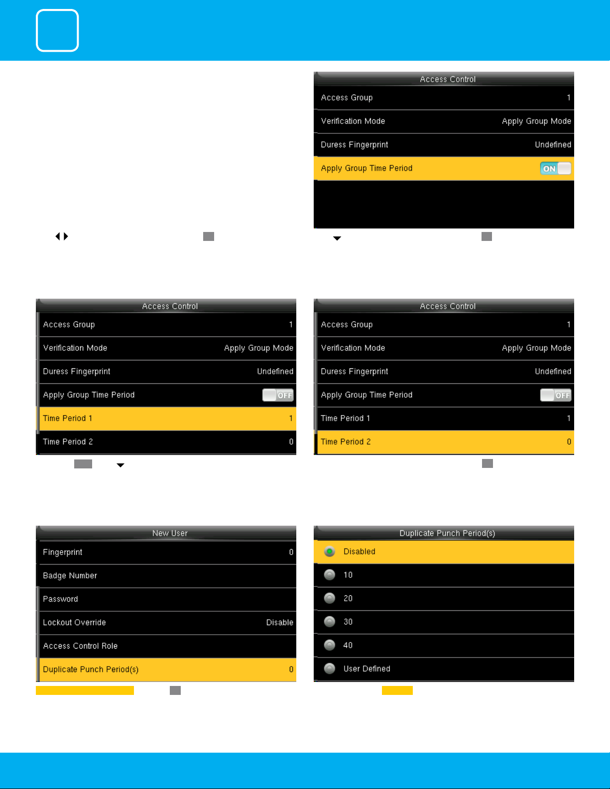
Press | to select enrolled ngerprint and press OK.
If selecting OFF , Press to select Time period 1.
Press to select Apply Group Time Period, press OK to select to whether
the user use his/her group’s default time zone.
Similarly, you can choose time period 2 and press OK.
Select duplicate punch period and press OK. Here you can select Disabled or select the punch period you want.
13
1
USER MANAGEMENT
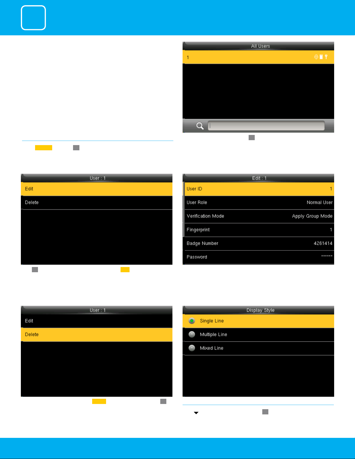
1.2 ALL USERS
Select
All users and press OK.
Press OK to enter User Info interface. Here you can Edit the user information. The User ID cannot be modied, and the other operations are similar to
Press to select “All User and press” OK.
those performed to add a user.
If you want to delete the user select Delete as shown above and press OK
and the user will get deleted.
1.3 SINGLE LINE
Press
14
to select display style and press OK to return.

1
USER MANAGEMENT
Single Line
Mixed Line
Multiple line
15

2
USER ROLE
2
USER ROLE
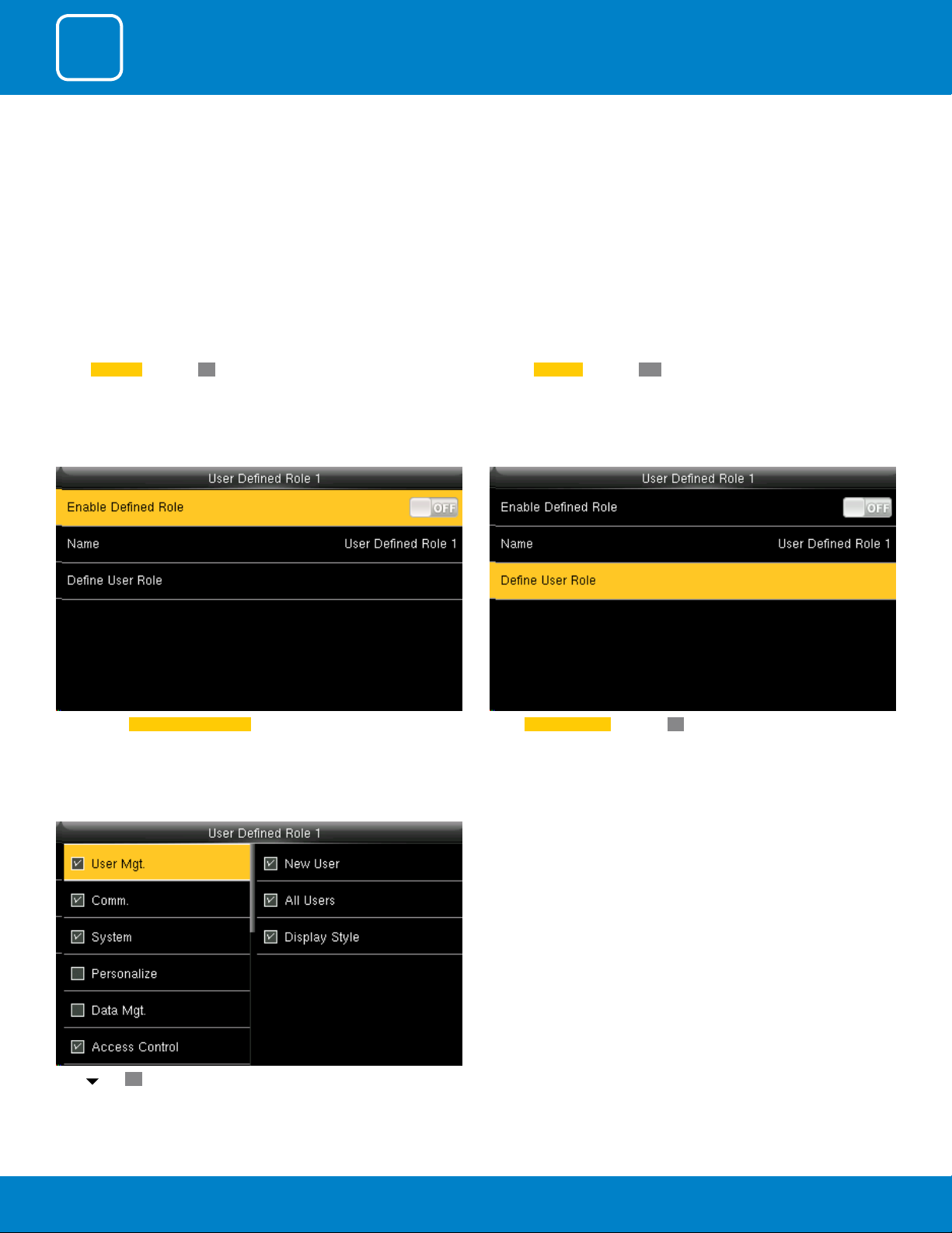
Select User Role and press OK.
Click on Registrar and press OK
He is also able to view “Standard Attendance Data” for existing users on the
clock
Select Dene User Role and press OK.Here you can Enable the dened Role for user by turning it ON.
Press and OK to select the rights. Press ESC to exit.
17

3
COMMUNICATION

3
COMMUNICATION
Go to menu and select “COMM” and press OK
IP Address: IP is 192.168.1.201 by default. You can modify it if it is necessary.
But it cannot be the same with that of PC.
3.1ETHERNET
Select
Ethernet and press OK
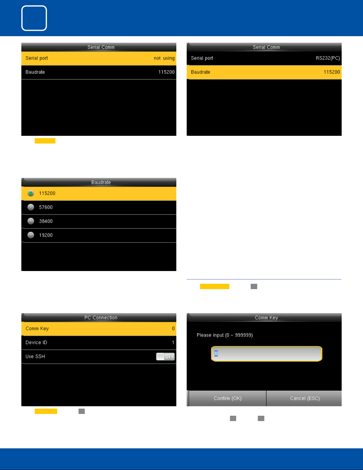
3.2 SERIAL COMMUNICATION
Select
Serial Comm and press OK.
Select Serial Port and press OK.
RS232: Whether or not to use RS232 to communicate. Select YES if RS232 is
to be used.
19
3
COMMUNICATION
Select Serial Port as not using if you do not want to use the port.
There are ve options: 9600, 19200, 38400, 57600 and 115200. If the communication speed is high, RS232 is recommended. If the communication speed
is low, RS 485 is recommended
Baudrate: Used for communication with PC.
3.3 PC CONNECTION
Select
PC connection and press OK.
Select Comm Key and press OK
Enter a password, using the keypad in the input box as shown above and to
select select Conrm
20
OK and press OK.
3
COMMUNICATION
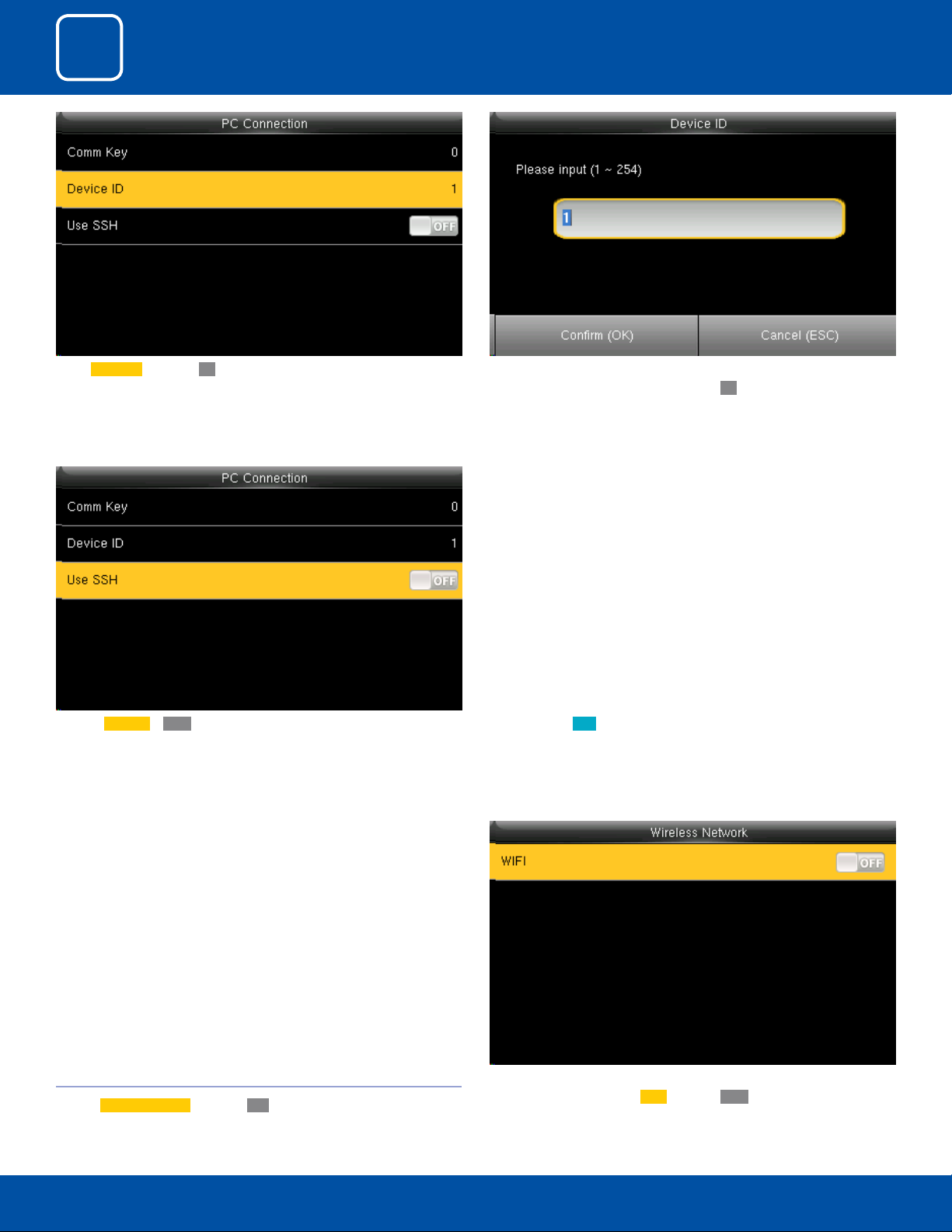
Select Device ID and press OK.
Here the Use SSH is OFF When you turn ON the “SSH” function the device will restart automatically
Here you can put the number for this device by using the keypad in the
input screen as above and hit press conrm
as shown above.
When this function is enabled you cannot “Telnet” into the clock as it will
disable that function.
OK.
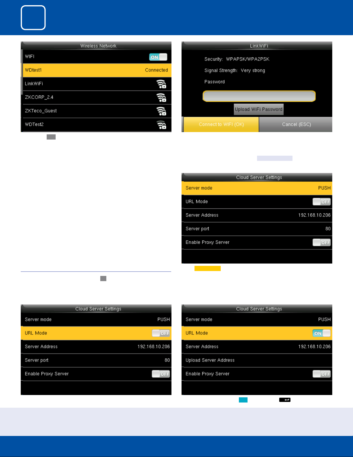
3.4 WIRELESS NETWORK
Click on
Wireless Network and press OK
When you select the wireless network option the following window will
appear in which as a default
21
WIFI would be OFF .
3
M/
COMMUNICATION
You can turn ON the wireless network and the networks available in the
range would be displayed as above.
3.5 CLOUD SERVER SETTINGS
Click on “Cloud Server Setting” and press
OK
You can select any wireless network you wish to connect and you can upload the password via “USB” or by using the keypad on the clock.
Once you upload the password you can press “Connect to WFI(OK)” and the
following network will get connected.
Select Server mode as “PUSH” as shown above.
It refers to your push server address.
See NOTE below
Here the “URLMode” is OFF”.
You can turn the “URLmode” ON by pressing the
button on the clock.
NOTE: The new lename for uploading Wi-Fi password or URL Webserver: updataoptions2.cfg
Inside this le you can either use: WirelessKey= [for uploading Wi-Fi password] or ICLOCKSVRURL= [for uploading webserver URL]
The clock won’t accept saving those two congurations under the same lename. Our suggestion would be to save one separate le for Wi-Fi and one for URL.
22
3
COMMUNICATION
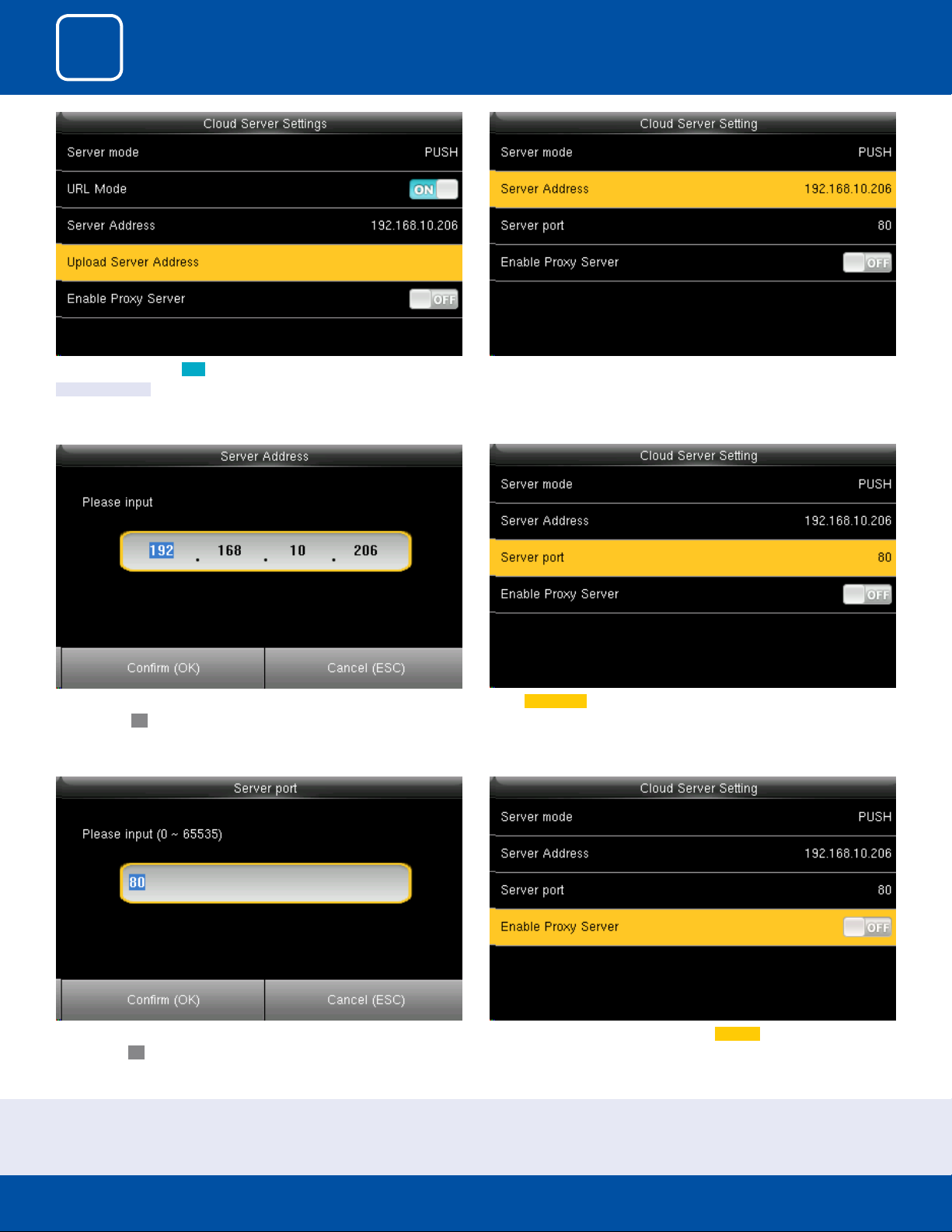
Once the “URL Mode” is ON you can upload the server address with “USB”.
See NOTE below
Here you can change server port of the webserver by using the keypad and
press conrm
OK.
Here the server address is the IP address of the webserver.
Select Server port. It is a port which is used by the webserver.
Here you can change server port of the webserver by using the keypad and
press conrm
OK.
Here you can select the proxy server to be Enabled or not. If it is o as above
the proxy server will be disabled.
NOTE: The new lename for uploading Wi-Fi password or URL Webserver: updataoptions2.cfg
Inside this le you can either use: WirelessKey= [for uploading Wi-Fi password] or ICLOCKSVRURL= [for uploading webserver URL]
The clock won’t accept saving those two congurations under the same lename. Our suggestion would be to save one separate le for Wi-Fi and one for URL.
23
3
COMMUNICATION
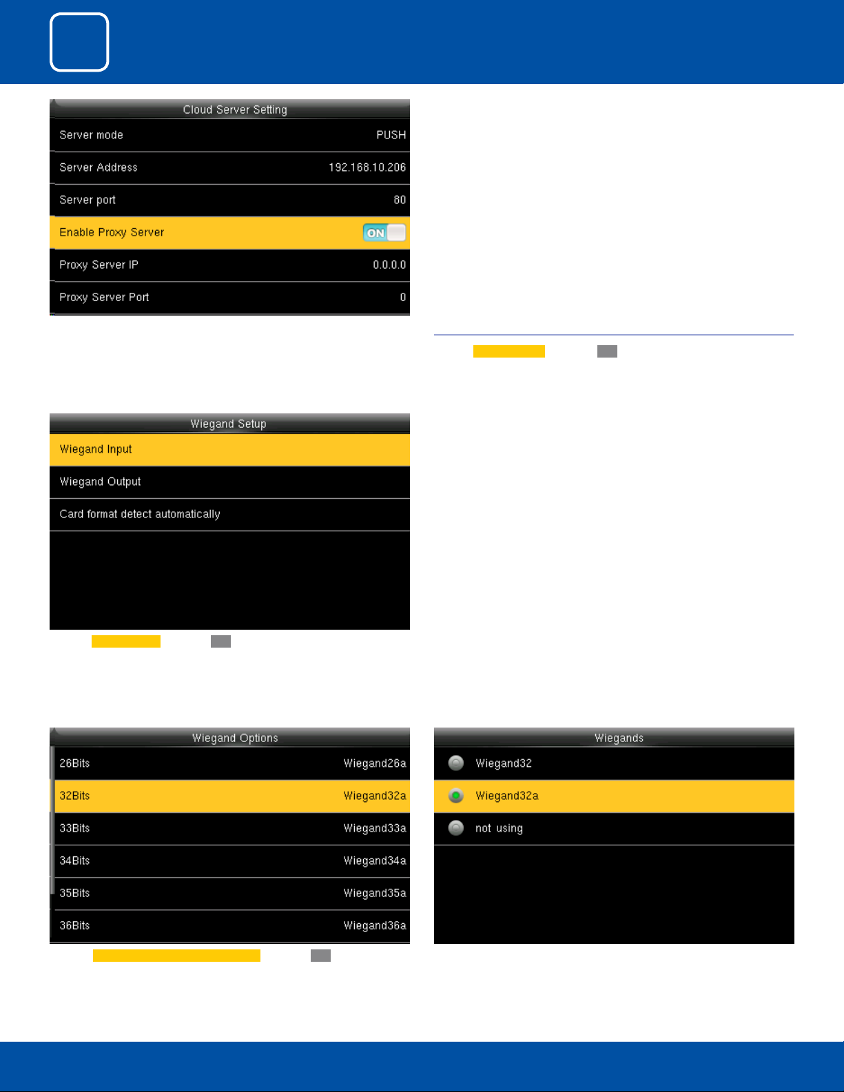
When you enable the proxy function, set the IP address and port number of
the proxy server. This option indicates whether to use a proxy IP address. You
may choose to enter the proxy IP address or the server address for Internet
access, whichever you like.
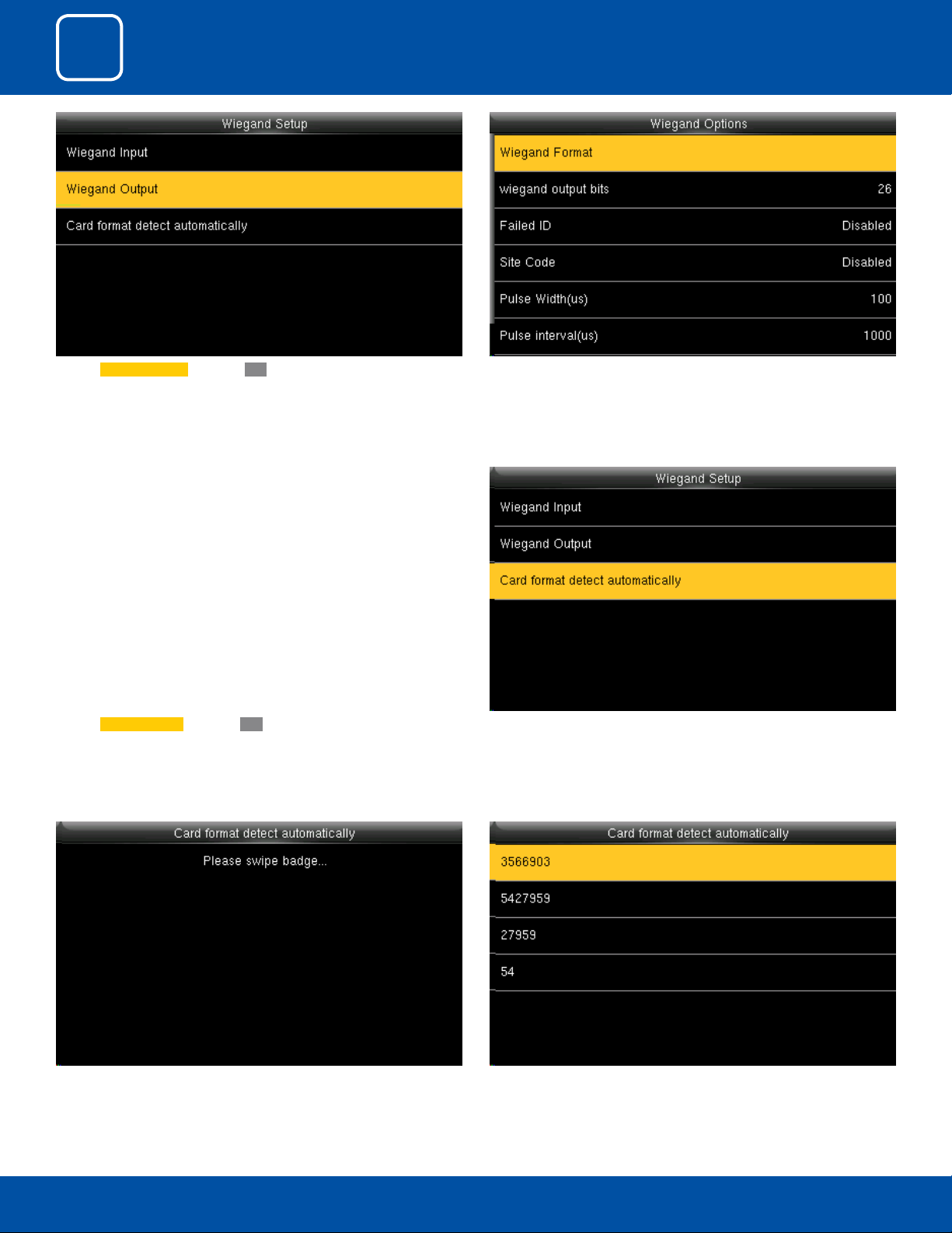
3.6 WIEGAND SETUP
Click on
Wiegand Setup and press OK .
You can select any Wiegand format of the card from the above options.Click on Wiegand Input and press OK
To select 32 bits Wiegand format click on 32 Bits and press OK .
When you select 32 bits you can select what type of 32 Wiegand format
from above
24
3
COMMUNICATION
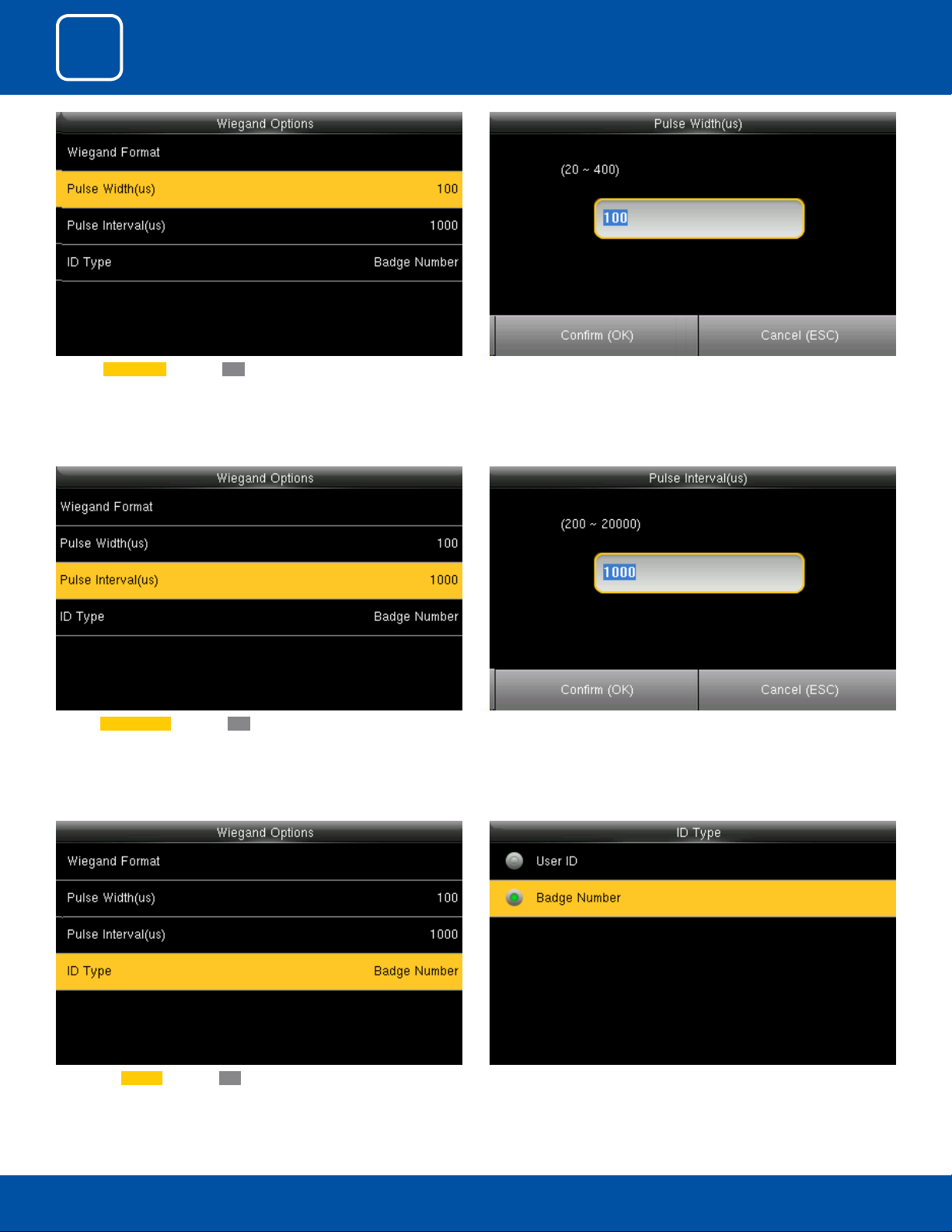
Click on Pulse Width and press OK .
Click on Pulse Interval and press OK
Here you can edit the Pulse width by using the keypad on the clock.
The Pulse Width ranges from 20 to 400 (us).
Here you can edit the Pulse Interval by using the keypad on the clock.
The Pulse Interval ranges from 200 to 20000 (us).
25
You can select the type of the ID from the options above.Click on the ID Type and press OK .
3
COMMUNICATION
Here you can edit the Wiegand Output options you wish to apply.Click on Wiegand Output and press OK .
Click on Wiegand Setup and press OK
Here you can swipe the multiple types of cards with dierent Wiegand
formats.
Click on “Card format detect automatically” and press “OK”.
(This function is available only for standard RFID and HID proximity Cards )
After you swipe the multiple cards all the cards with dierent Wiegand
formats will be displayed as above.
26
3
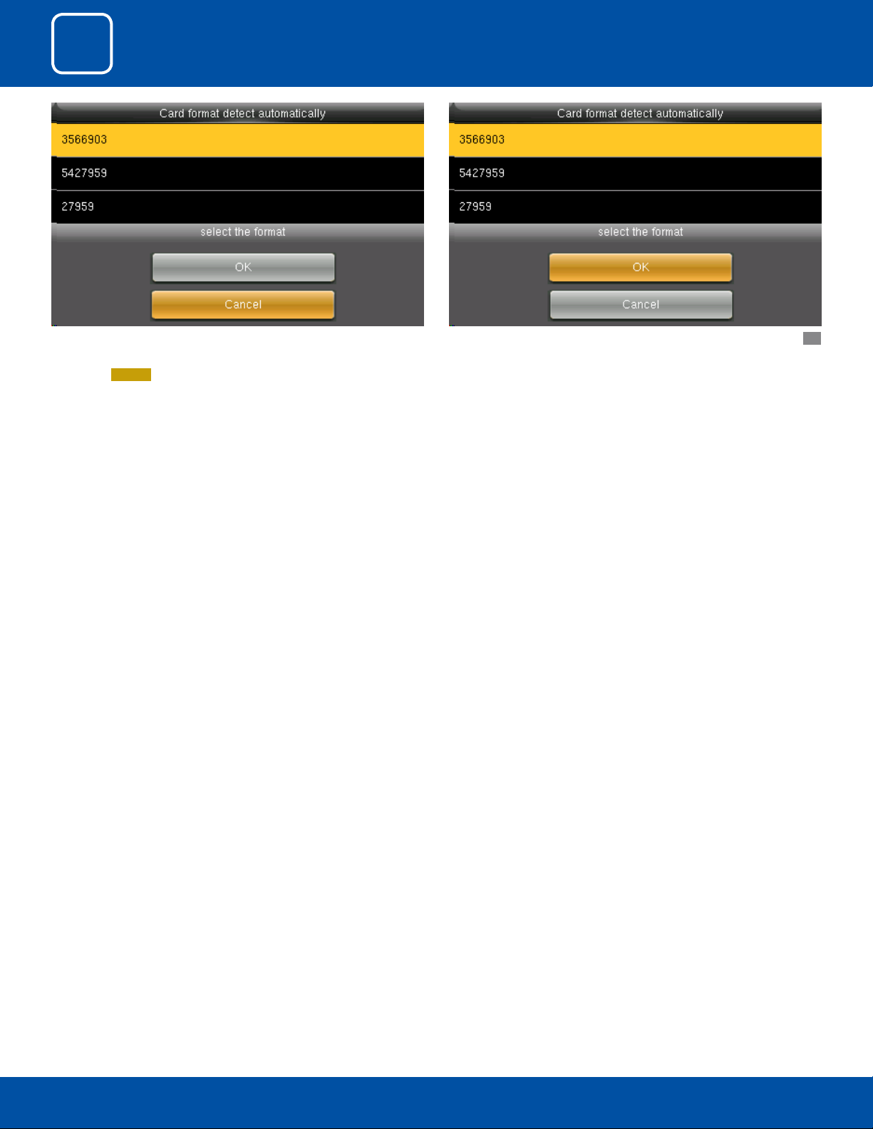
COMMUNICATION
Here you can select the Wiegand format of the card you wish to choose to
register.
If you select
Cancel that Wiegand format would not be selected.
To select the particular Wiegand card format select that format and press OK
as shown above..
27

4
SYSTEM
3
4
COMMUNICATION
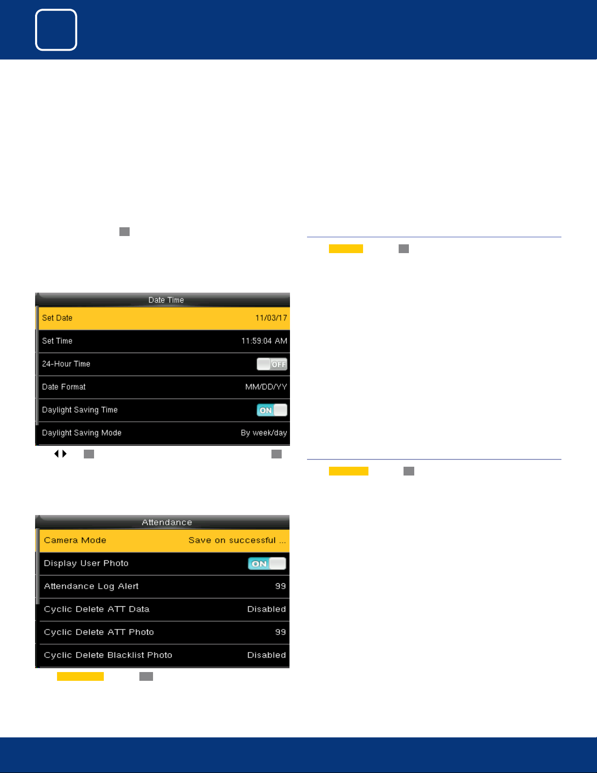
Select “System” and press OK 4.1 DATE TIME
SYSTEM
Select
Date Time and press OK.
Press | and OK to select items. When the setting is completed, press OK
to save the setting and exit.
Select Camera Mode and press OK
4.2 ATTENDANCE
Select
Attendance and press OK.
29
29
3
4
COMMUNICATION
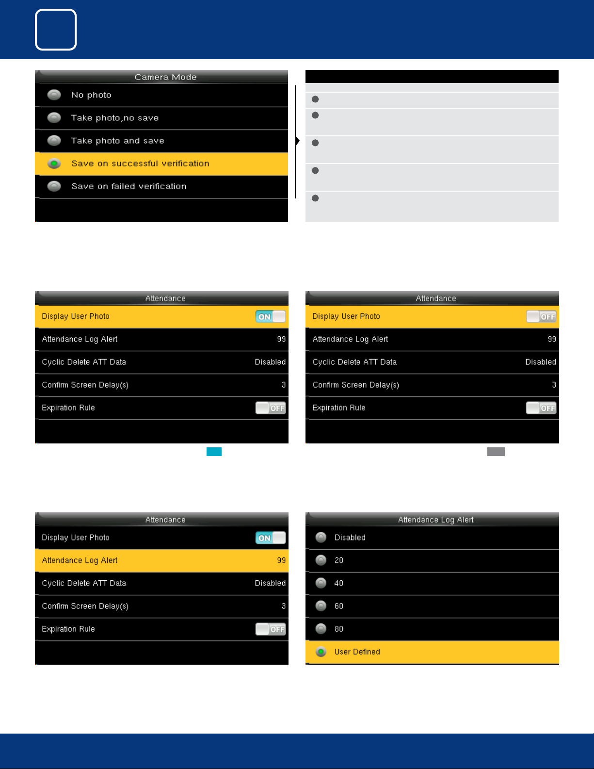
Here you can select the dierent mode of camera you want to set for the
device.
SYSTEM
CAMERA MODES
No photo Camera will not take any picture.
•
Take Photo, no save Camera will take the picture but image will not
•
save in the terminal
Take photo and save Camera will able to take a picture and save it in
•
the terminal
Save on successful verication If you select this option the images
•
of the user will be saved if they make successful punch.
Save on failed verication This will save the images of the users
•
even if their verication fails on the device.
If you want to display the user photo you can select ON If you don’t want the user photo to be displayed select OFF as above.
When the available space is insucient to store the specied number of
attendance records, the FFR terminal will automatically generate an alarm.
(Value scope: 1-99)
You can change the value for attendance log alert from the image above.
30
30
 Loading...