

ZKTeco F6 Installation Manual
GND
SEN
BUT
BELL+
BEL L-
DC12V
-
+
GND
+12V
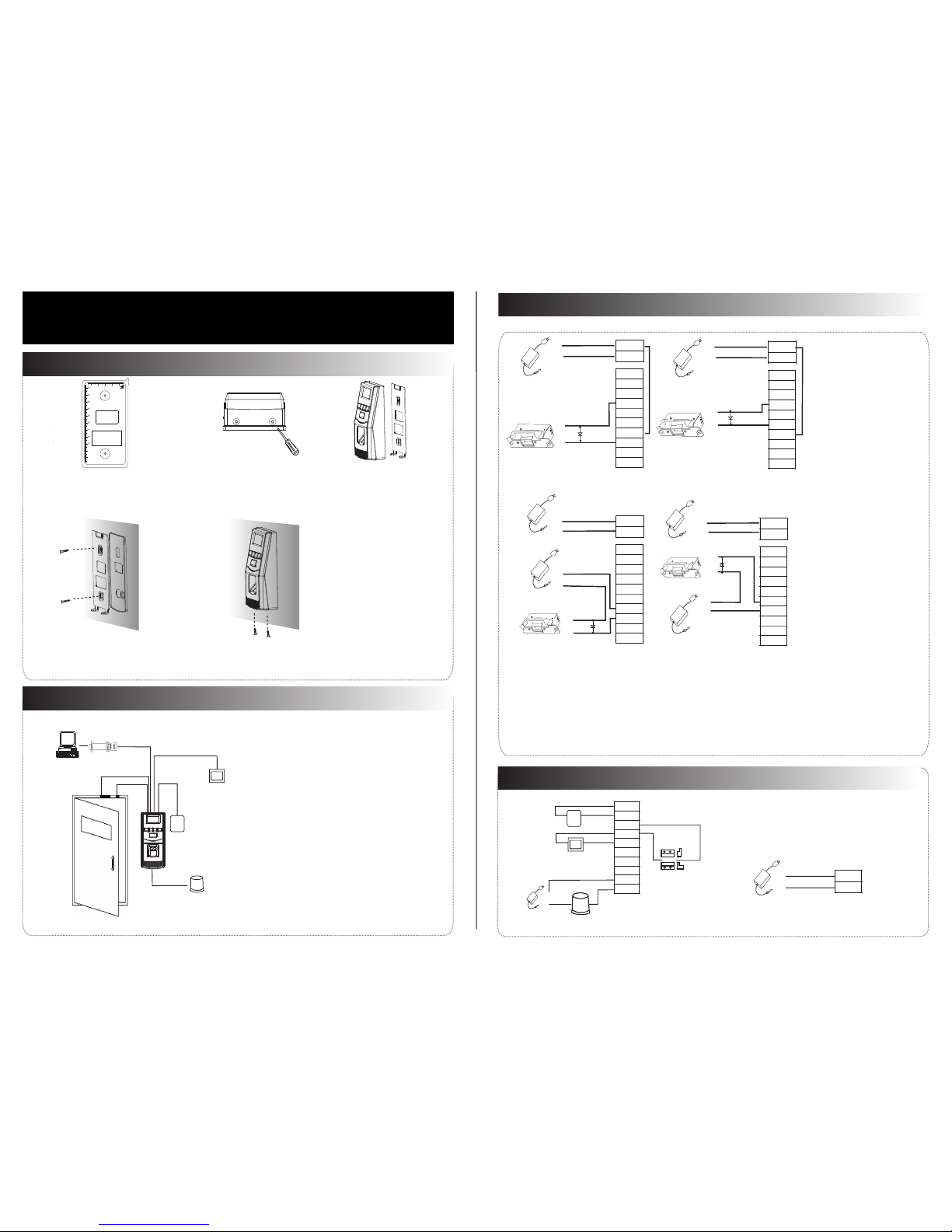
Door Bell
%
EXIT
BUTTON
-
+
Alarm
Alarm Power
Exit Button
Door Sensor
Alarm Voltage output ≤ DC 12V
4. Other Parts Connection:
5. Power Connection:
Input DC 12V, 500mA (50mA standby). Positive
is connected with ‘+12V’, negative is connected
with ’GND’ (do not reverse the polarities).
NC1
NO1
COM1
NO2
COM2
(1) Post the mounting template on the
wall, drill the holes according to
the marks on the template (holes
Version: V1.2 Date: March, 2012
(2) Remove the screws on the
(3) Take away the back plate
(5) Tighten the screws on the bottom,
pla te on the w all acc ordin g to
(4) F ix the pl astic p ad and th e back
RS485
Lock
Sensor
①
③
Alarm
RS485 Converter
②
NC LOCK
-
+
DC12V
+
NC LOCK
+
-
NO LOCK
-
-
FR 107
+
-
+12V
+12V
+12V
+12V
GND
GND
GND
GND
GND
GND
GND
GND
SEN
SEN
SEN
SEN
BUT
BUT
BUT
BUT
BELL+
BELL+
BELL+
BELL+
BEL L-
BEL L-
BEL L-
BEL L-
NO LOCK
-
+
DC12V
+
-
+
-
FR 107
FR 107
-
+
DC12V
+
-
-
+
DC Power
-
+
DC12V
-
+
DC Power
+
-
FR 107
+
Exit Button
⑤
④
Door Bell
%
BUTTON
EXIT
⑥
for screws and wiring).
bottom of the device.
Access Control System Function
(1) If a registered user verified, the device will export
the signal to unlock the door.
(3) If the device is removed illegally, it will output an
(4) External exit button is supported, it is convenient to
(5) External door bell is supported.
(2) Door sensor will detect the on-off state. If the door is
unexpected opened or improperly closed, the alarm
signal (digital value) will be triggered.
alarm signal.
open the door inside.
can manage multiple devices.
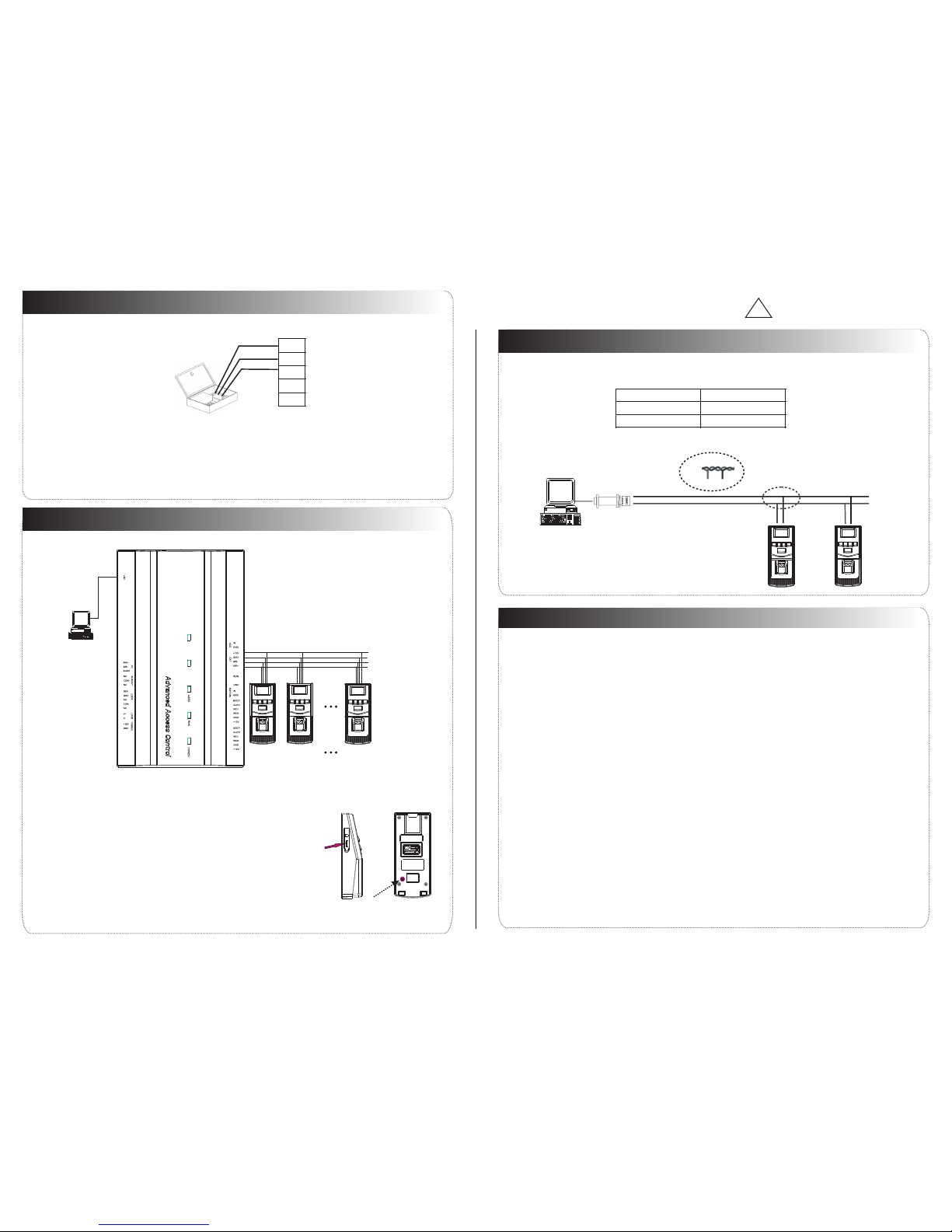
(6) Supports RS485 mode to connect with PC. One PC
①: ‘‘I’: Device output current, ‘ ’: Lock voltage, ’: Lock current.ULOCK ILOCK
(1) The system supports NO LOCK and NC LOCK. For example the NO LOCK (normally open at
(2) When the Electrical Lock is connected to the Access Control System, you need to parallel one FR107
power on) is connected with ‘ ‘ ’NO’ and COM terminals, and the NC LOCK(normally close at power on )
3.Lock Connection
(1) Share power with the lock:
ULOCK=12V, I-ILOCK>1A…①
The distance between the lock
Device shares power with the lock:
Does not shares power with the lock:
A. =12V I- ≤1A;ULOCK ILOCK
B ≠12V; . ULOCK
C. The distance between the lock and
(2) Does not share power with the lock:
2. Structure and Function
F6 Installation Guide
1. Equ ipmen t Insta llati on
NC1
NC1
NC1
NC1
NO1
NO1
NO1
NO1
COM1
COM1
COM1
COM1
NO2
NO2
NO2
NO2
COM2
COM2
COM2
COM2
fix the device to the back plate.
Wiring Hole
Instruction for t he Moun ting Pa per
Before the device i s faste ned, pl ease
stick the paper to th e place w here yo u
want to install it, t hen mak e holes a nd
lay cables accord ing to th e mount ing
paper.
F6 Mounti ng Pape r
(only for y our ref erenc e)
Fixing Hole
Fixing Hole
10
11
the m ounti ng pape r.
is connected with ‘NC’ and ‘COM’ terminals.
Notes:
diode (equipped in the package) to prevent the self-inductance EMF affecting the system, do not
reverse the polarities.
and the device shares Ilock 1A
the device is more than 10 meters.
is equal or less than10 meters.
Access Control Panel
Side View Back View
Tamper Magnet
Reset Button
485+
485-
485+ 485-
9. Cautions
6. Wiegand Output
The device supports standard Wiegand 26 / Wiegand 34 output, so you can connect it with most of
(Please use Wiegand signal extender in long distance or interference environment).
(2) To keep the stability of Wiegand signal, connect the device and the Access Control or Card Reader in
(1) Please keep the distance between the device and Access Control or Card Reader less than 90 meters
7.Other Functions
(1) Manual Reset:
other restart it.abnormality, you can use ‘Reset’ function to
button hole with than 2mm).a sharp tool (the tip diameter is less
Operation: Remove the black rubber cap,then stick the Reset
If the device does not work properly because of misoperation or
!
Warning: No operating with power on!
same ‘GND’ in any case.
485+
485-
GND
WD0
WD1
DATA0
GND
DATA1
8. Communication
This device could use RS485 mode to communicate and exchange information with PC software
Please use specified RS485 wire, RS485 active converter, and adopt bus-type wiring.
About the terminals definition, please refer to the following table:
and supports remote control.
RS485 Bus
485+ 485- 485+ 485-
RS485
Converter
the access control devices by now.
(2) We recommend that use the DC 3A/12V power supply. For details, please contact our technical
"
(5) Please connect the GND before all the other wiring especially under the serious
"
electrostatic environment,
(3) Please read the terminals description and wiring by rule strictly. Any damage caused by carefully
(4) Keep the exposed part of wire is less than 5mm to avoid unexpected connection, and result in machinery
(1) Power cable is connected after all the o ther wiring. If the device is abnormally, please shutoperated
do wn the power firstly, then make some hot-necessary checking. Kindly remain that any
improper operations will be out of the range of our guarantee.
to prevent the overlarge instantaneous electrostatic to damage device.
(
6) If the pow er supp ly is a li ttle lo ng, ple ase do no t use the I ntern et
cab le or oth er type s of cabl e inste ad. Whe n cho osing t he powe r suppl y cable , you sho uld
con sider t hat the t ransm issio n dista nce may c ause vo ltage a ttenu ation .
dis tance b etwee n and d evice
plugging may damag e device, and it is not included in the warranty.
damage.
(7) Please use specified RS485 wire, RS485 active converter, and adopt bus-type wiring. If the communication
485+
Terminals PC Serial Ports
RS485+
485- RS485-
wire is longer than 100 meters, it is needed to parallel a terminal resistance on the last device of Rs485 bus,
and the value is about 120 ohm.
personnel or sales.
(2) Tam pe r Swi tc h (Ba ck doo r Fu nct ion):
be cl eared .
Operation: Press the tamper switch three times after the alarm being
You can u se the ta mper sw itch to r estor e devic e numbe r, syste m
pas sword , clear a dmini strat or priv ilege s. The us er da ta will n ot
triggered 30 seconds,but not more than 60 seconds.
(1) As Reader:
EXT
RS485
PC
RS485
STATE
PWR
READER2READER1
SWITCH
OUT
ACT
PC
Access Control Panel
Connected with Reader(with External 485),
the maximum can connecting 8 readers.
#1 Reader #2 Readers #8 Readers
+12V
485-
GND
485+
 Loading...