

ZKTeco F305 User Manual

F305
USER MANUAL
Version 2 - April 2019

CONTENT
USER MANAGEMENT 5
1
1.1 New User ...................................................................... 6
1.2 All Users ........................................................................ 10
1.3 Single Line ..................................................................... 11
USER ROLE 13
2
COMMUNICATION 15
3
3.2 Serial Communication .......................................................16
3.1Ethernet ........................................................................16
3.3 PC Connection ................................................................ 17
3.4 Wireless Network ............................................................. 18
3.5 Cloud Server Settings ........................................................ 19
3.6 Wiegand Setup ............................................................... 21
SYSTEM 22
4
4.2 Attendance .................................................................... 23
4.1 Date Time ...................................................................... 23
4.3 Face .............................................................................25
4.4 Reset ...........................................................................27
4.5 USB Upgrade .................................................................. 27
PERSONALIZE 28
5
5.1 User Interface ................................................................. 29
5.2 Voice ............................................................................31
5.3 Bell Schedules ................................................................. 32
5.4 Punch State Options.........................................................35
5.5 Short-cut Key Mapping ...................................................... 36

CONTENT
DATA MANAGEMENT 41
5
6.1 Delete Data .................................................................... 42
6.2 Backup Data ..................................................................43
6.3 Restore Data ...................................................................44
ACCESS CONTROL 46
7
7.1 Time Schedule
7.2 Access Group .................................................................47
USB MANAGER 50
8
8.1 Download .....................................................................51
8.3 Download Options ...........................................................52
8.2 Upload .........................................................................52
ATTENDANCE SEARCH 54
9
SHORT MESSAGE 56
10
10.1 New Message ................................................................ 57
10.3 Personal messages .......................................................... 59
10.2 Public Messages .............................................................59
10.4 Draft Messages .............................................................. 59
10.5 Message Options ........................................................... 60
................................................................ 47
WORK CODE 61
11
11.1 New Work Code .............................................................62
11.2 ALL WORK CODES ........................................................... 63
11.3 WORK CODE OPTIONS ..................................................... 63

CONTENT
JOB CODE 65
12
12.1 New Job Code ...............................................................66
12.2 All Job Code ................................................................. 67
12.2 All Job Codes ................................................................ 70
12.3 Job Code Options ........................................................... 73
12.4 Job Group Option Menu Operation ...................................... 75
TIP CODE 78
13
13.1 Tip code settings ............................................................ 79
13.2 Tip code ...................................................................... 80
AUTO TEST 84
14
14.1 All Test ........................................................................85
14.2 Test LCD ...................................................................... 85
14.3 Test Voice .....................................................................87
14.6 Test CLOCK RTC ..............................................................87
14.4 Test FACE ..................................................................... 87
SYSTEM INFORMATION 88
15
15.1 Device Capacity .............................................................89
15.2 Device Info ................................................................... 89
15.3 Firmware Info ...............................................................90

1
USER MANAGEMENT
1
USER MANAGEMENT
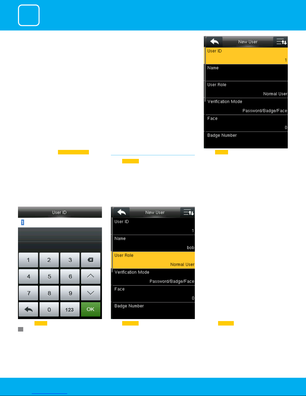
1.1 NEW USER
Select
New User .
Select User ID Go to menu and select User Management .
OK.
Click on Registrar Select User Role Enter the User ID by using the keypad and press
6

1
USER MANAGEMENT
A user with “Registrar” is able to “Add”, “Delete” and
“Edit” standard users to the device.
He/She is also able to view “Standard Attendance
Data” for existing users on the clock.
Select Apply Group Mode. By pressing the apply
group mode the user can verify himself with
all the options that are available in verication
mode.
Select Verication Mode .
Verication mode is basically used to verify the
user.
Select Apply Group Mode .By pressing the apply
group mode the user can verify himself with
all the options that are available in verication
mode.
By clicking the option above the user can verify
himself either with his/her
Fingerprint/Password or Badge .
7
Select Verication Mode ..
1
USER MANAGEMENT
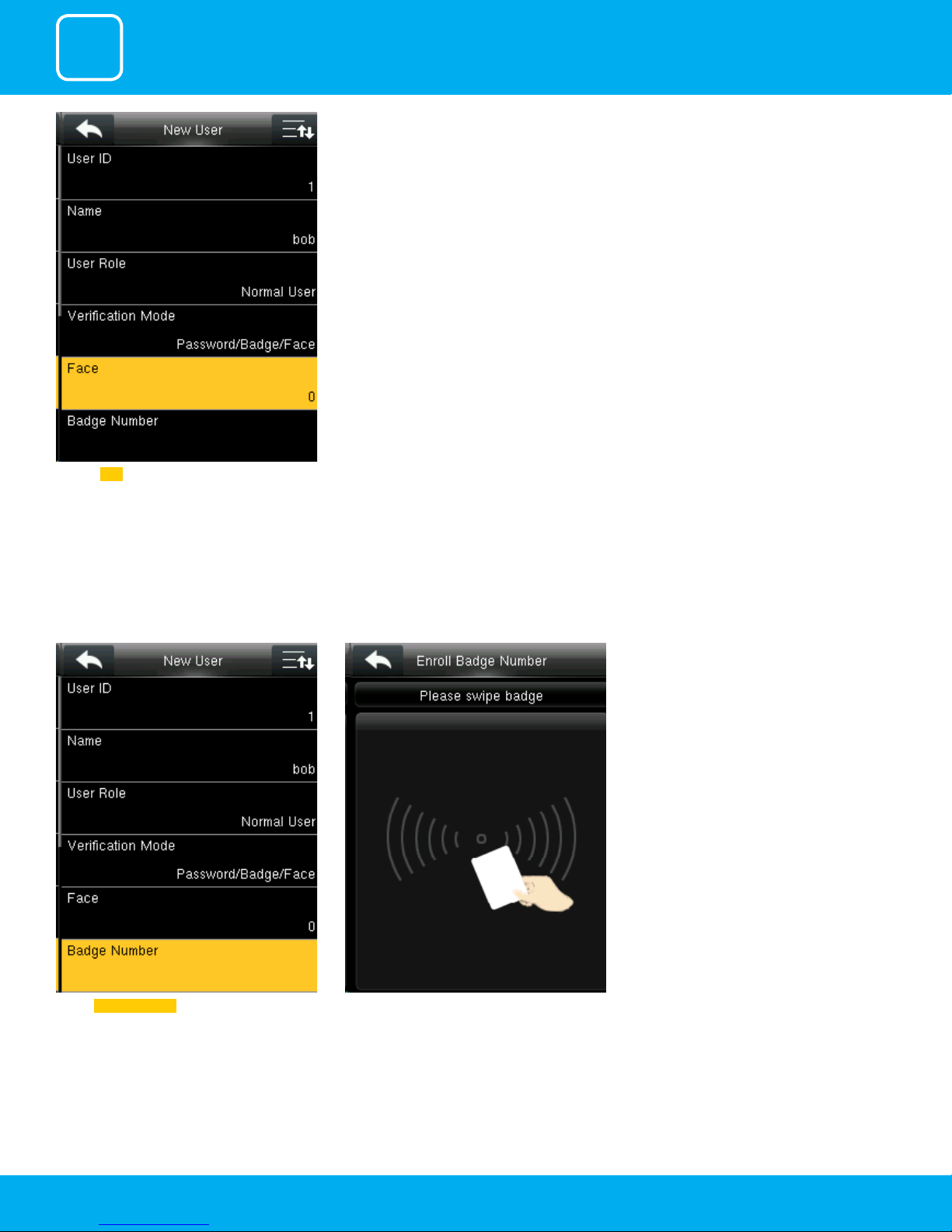
Click on Face . Place your eyes inside the green box Adjust your face according to instruction.
The user face will be enrolled successfully
Select Badge Number ..
When you select the badge number it will tell
you to swipe the badge/rd card to enroll.
8
When you swipe the badge number the badge
number will be displayed as above.
1
USER MANAGEMENT
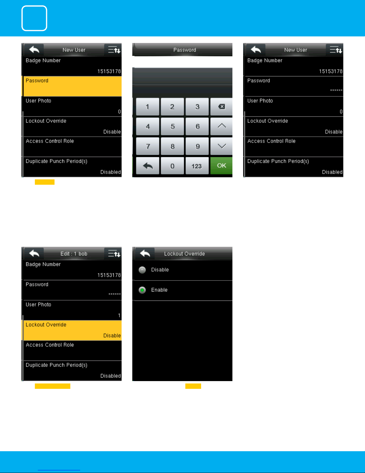
Select Password .. Here you can input the password by using the
keypad to enroll.
Once you entered the password, the above
image will be displayed for that user with his/her
ngerprint, the badge number and password
that is needed for him/her to enter.
Select lockout override as Disable .Select Lockout Override .
9
A user punches in o the activate schedules, the
device will notify the user by “Error! Invalid time
period Failed to verify.”
1
USER MANAGEMENT
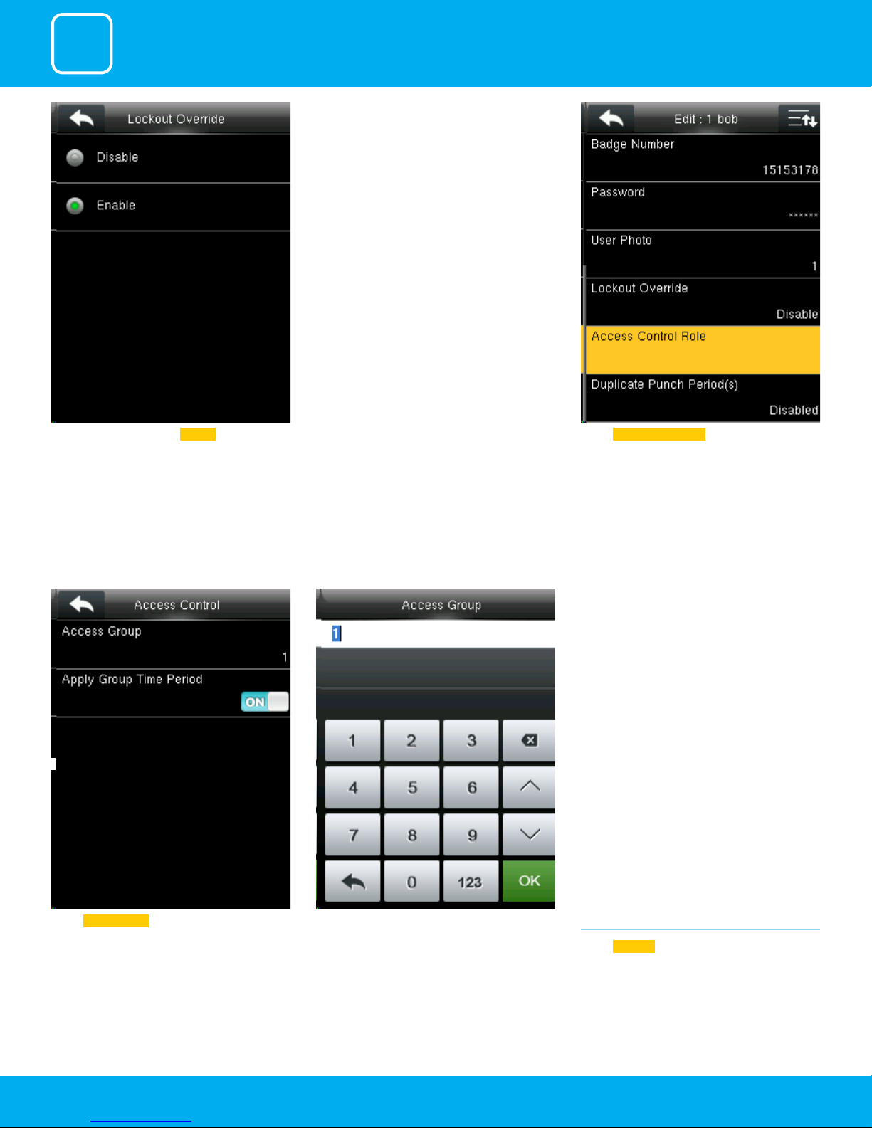
Select lockout override as Enable . A user punches in o the activate schedules, the
device will notify the use by “Successfully Veried.”
As shown above
Select Access Control Role .
Select Access Group .
You can change the number for that group in
the input section above using the keypad.
10
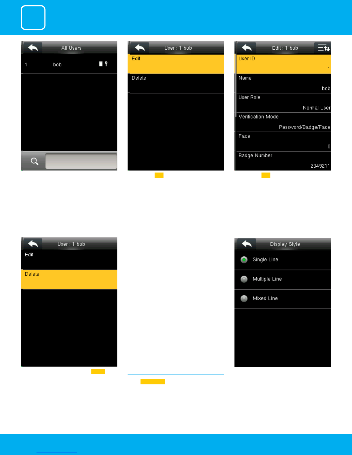
1.2 ALL USERS
Select
All users .
1
USER MANAGEMENT
Press to select “All User.
Here you can Edit the user information.
Here you can Edit the user information.
If you want to delete the user select Delete as
shown above and the user will get deleted.
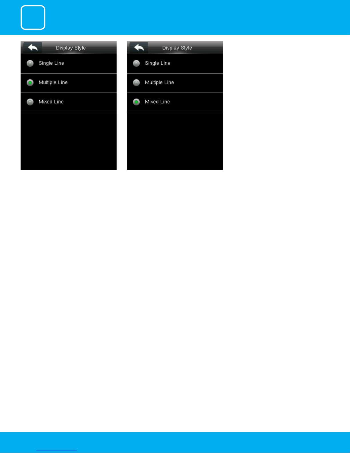
1.3 SINGLE LINE
Select
Display Style .
Single Line.
11
1
USER MANAGEMENT
Multiple line. Mixed Line.
12

2
USER ROLE
2
USER ROLE
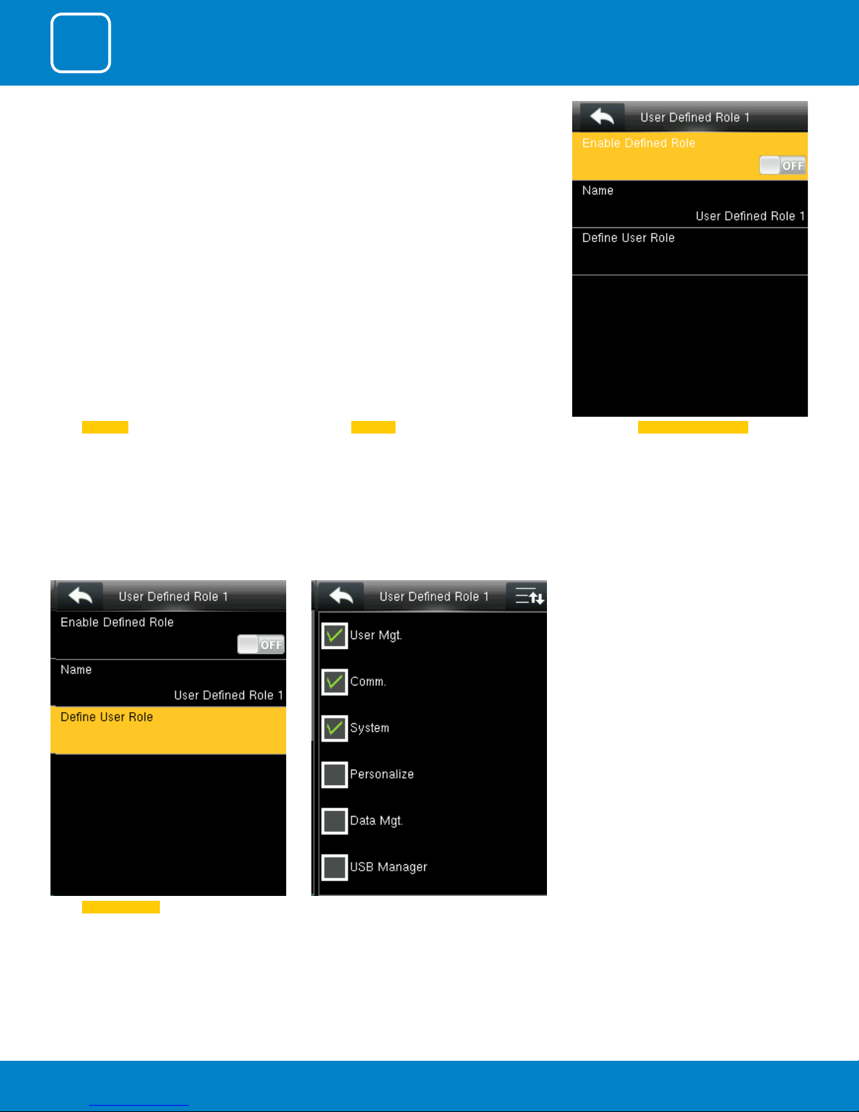
Select User Role
Click on Registrar
He is also able to view “Standard Attendance
Data” for existing users on the clock
Here you can Enable the dened Role for user by
turning it ON.
Select Dene User Role . Select the rights from options above.
14

3
COMMUNICATION
3
COMMUNICATION
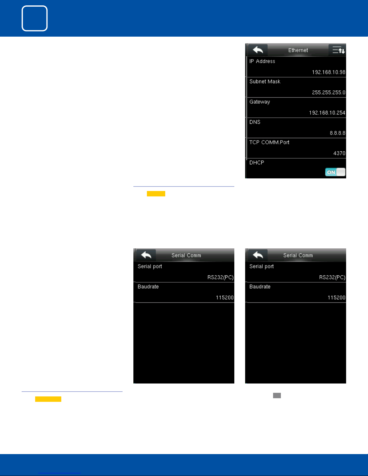
Go to menu and select “COMM”. 3.1ETHERNET
Select
Ethernet .
IP Address: IP is 192.168.1.201 by default. You can
modify it if it is necessary. But it cannot be the
same with that of PC.
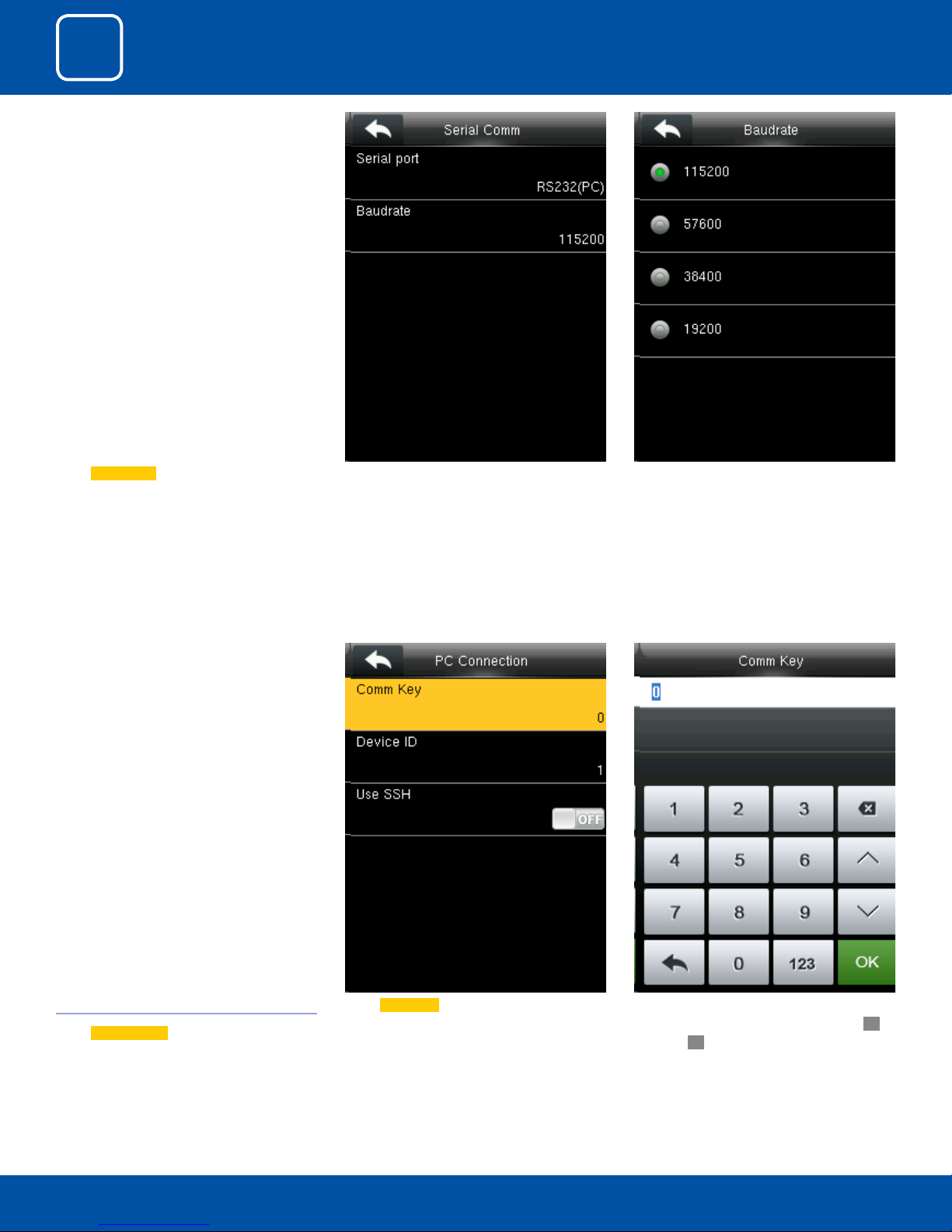
3.2 SERIAL COMMUNICATION
Select
Serial Comm .
Select “Serial Port”.
16
RS232: Whether or not to use RS232 to communicate. Select
YES if RS232 is to be used.
3
COMMUNICATION
Select Serial Comm as not using if you do not
want to use the port.
Baudrate: Used for communication with PC.
There are ve options: 9600, 19200, 38400, 57600
and 115200. If the communication speed is high,
RS232 is recommended. If the communication
speed is low, RS 485 is recommended
Select
PC connection .
Select Comm Key .3.3 PC CONNECTION
17
Enter a password, using the keypad in the input
box as shown above and to select Conrm
and press
OK.
OK
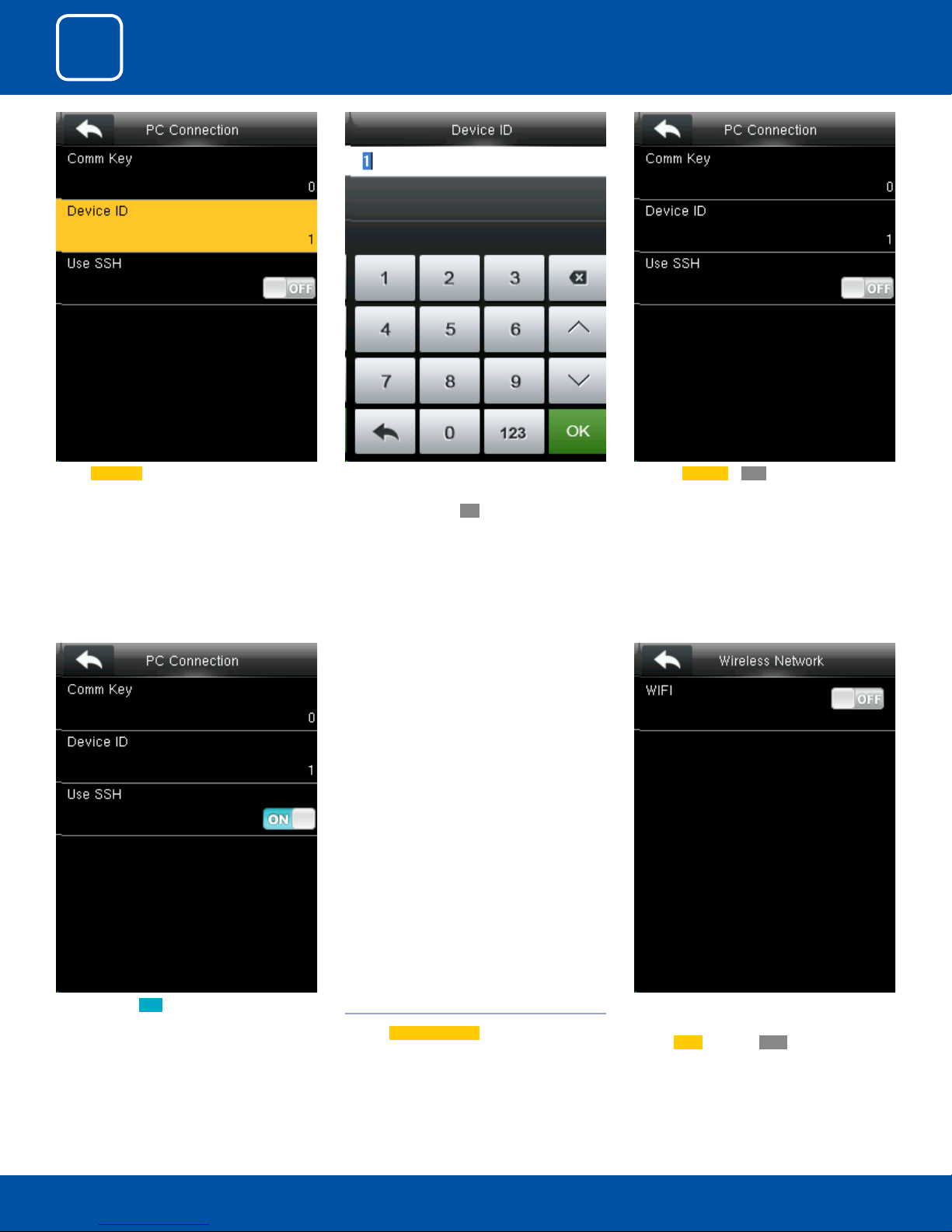
3
COMMUNICATION
Select Device ID . Here you can put the number for this device by
using the keypad in the input screen as above
and hit press conrm
OK.
Here the Use SSH is OFF
When you turn ON the “SSH” function the device will restart automatically as shown above.
When this function is enabled you cannot “Telnet” into the clock as it will disable that function.
3.4 WIRELESS NETWORK
Click on
Wireless Network .
18
When you select the wireless network option
the following window will appear in which as a
default
Wi-Fi would be OFF .
3
COMMUNICATION
You can turn ON the wireless network and
the networks available in the range would be
displayed as above.
You can select any wireless network you wish to
connect and you can upload the password via
“USB” or by using the keypad on the clock.
Once you upload the password you can press
“Connect to Wi-Fi (OK)” and the following network will get connected.
See NOTE below
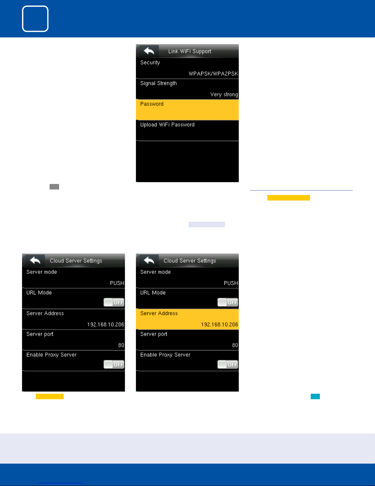
3.5 CLOUD SERVER SETTINGS
Click on
Cloud Server Setting
Select Server mode as “PUSH” as shown above.
It refers to your push server address.
NOTE: The new le name for uploading Wi-Fi password or URL Webserver: updataoptions2.cfg
Inside this le you can either use: WirelessKey= [for uploading Wi-Fi password] or ICLOCKSVRURL= [for uploading webserver URL]
The clock won’t accept saving those two congurations under the same le name. Our suggestion would be to save one separate le for Wi-Fi and one for URL.
Here the “URLMode” is OFF”. You can turn the “URLmode” ON .
19

3
COMMUNICATION
Once the “URL Mode” is ON you can upload the
server address with “USB”.
See NOTE below
Here the server address is the IP address of the
webserver.
Here you can change server port of the webserver by using the keypad and press conrm
OK.
Select Server port. It is a port which is used by
the webserver.
NOTE: The new le name for uploading Wi-Fi password or URL Webserver: updataoptions2.cfg
Inside this le you can either use: WirelessKey= [for uploading Wi-Fi password] or ICLOCKSVRURL= [for uploading webserver URL]
The clock won’t accept saving those two congurations under the same le name. Our suggestion would be to save one separate le for Wi-Fi and one for URL.
Here you can change server port of the webserver by using the keypad and press conrm
20
OK.
Here you can select the proxy server to be Ena-
bled or not. If it is o as above the proxy server
will be disabled.
3
COMMUNICATION
When you enable the proxy function, set the IP
address and port number of the proxy server.
This option indicates whether to use a proxy IP
address. You may choose to enter the proxy IP
address or the server address for Internet access,
whichever you like.
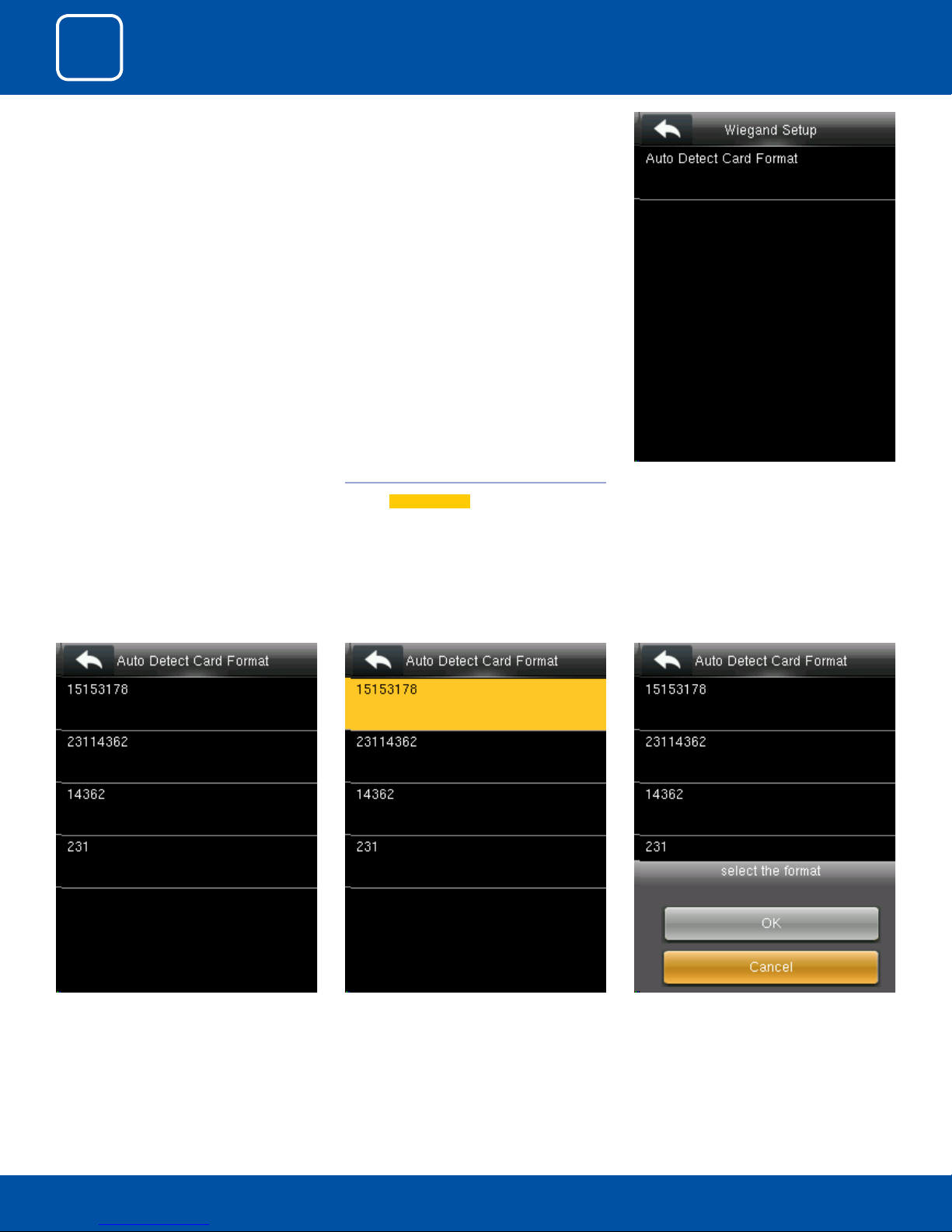
3.6 WIEGAND SETUP
Click on
Wiegand Setup .
Click Auto Detect Card Format.
You can select any Wiegand format of the card
from the above options.
You can select any type of card format by selecting that format
21
Once you select the card format press OK
The clock will read the card format you selected

4
SYSTEM
4
SYSTEM
Select “System”. 4.1 DATE TIME
Select
Date Time .
Here you can change the date and time from
settings above you wish to apply.
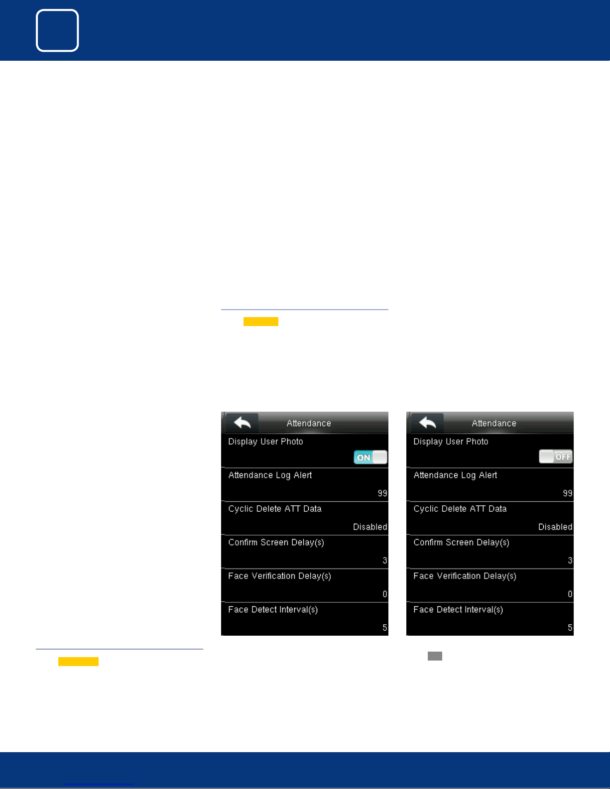
4.2 ATTENDANCE
Select
Attendance .
If you want to display the user photo you can
select ON
23
If you don’t want the user photo to be displayed
select
OFF as above.

4
SYSTEM
When the available space is insucient to store
the specied number of attendance records,
the FFR terminal will automatically generate an
alarm. (Value scope: 1-99)
You can change the value for attendance log
alert from the image above.
Select Cyclic Delete ATT Data. It species the
maximum number of attendance records that
can be deleted at a time when the number of
attendance records reaches the upper limit.
This function can be disabled; otherwise, the
value ranges from 1 to 999
The screen delay species the time for displaying
the authentication result.
24
The value ranges from 1s to 5s.
4
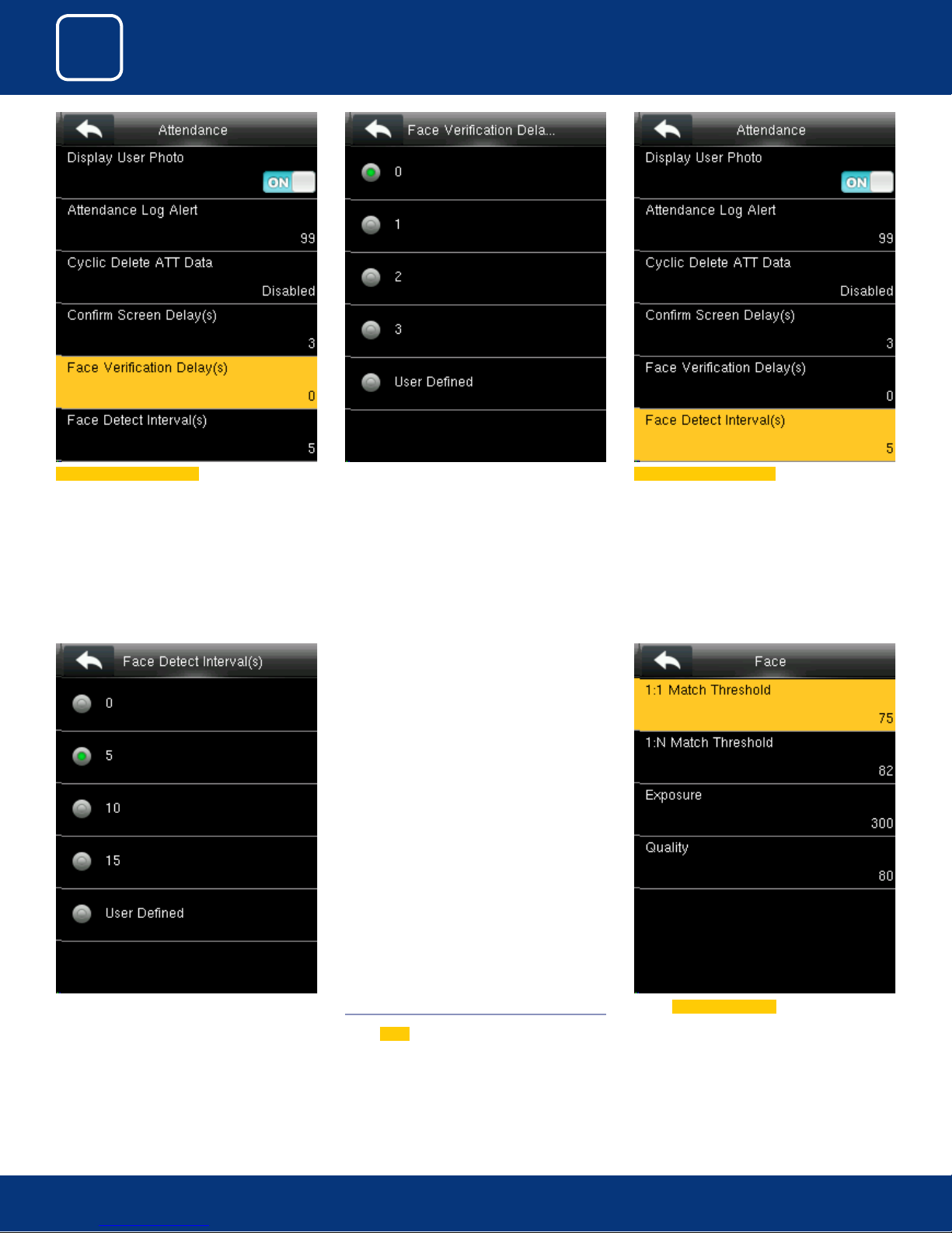
SYSTEM
Select Face Verication Delay
You can change the Delay for the verication of
the face from options above.
The time ranges in seconds
Select Face Detect Interval(s)
You can detect the Interval for the face from
options above.
The time ranges in seconds
4.3 FACE
Select
Face
Select 1:1 Match Threshold from above.
25

4
SYSTEM
From the above options change the threshold
value for1:1 verication.
Select 1:N Match Threshold from above. From the above options change the threshold
value for1:N verication.
Select Exposure
From the above options you can change the
exposure of the face you wish to apply.
26
You can change the Quality of the face from the
options above.

4
SYSTEM
4.4 RESET
Select
Reset .
When you select Cancel it will go back to previous menu.
If you select
the clock.
OK it will reset the setting and restart
4.5 USB UPGRADE
Select
USB Upgrade .
If the USB is not readable or properly insert the
image above will be displayed and you cannot
be able to upgrade.
27

5
PERSONALIZE
 Loading...