

ZKTeco F19 Installation Manual
(1) Paste the mounting template on the
wall. Drill the holes according to
the marks on the template (holes
Version: 1.0 Date: June, 2012
(2) Remove the screw on the
(3) Take away the back plate.
(5) Place the unit onto the mounting bracket,
pla te on the w all acc ordin g to
(4) F ix the ru bber pa d and the b ack
RS485
TCP/IP
Lock
Sensor
①
③
Alarm
RS232/RS485 Converter
②
NC LOCK
-
+
DC12V
+
NC LOCK
+
-
NO LOCK
-
-
FR 107
+
-
+12V
+12V
+12V
+12V
GND
GND
GND
GND
GND
GND
GND
GND
GND
SEN
SEN
SEN
SEN
SEN
BUT
BUT
BUT
BUT
BUT
BELL+
BELL+
BELL+
BELL+
BELL+
BEL L-
BEL L-
BEL L-
BEL L-
BEL L-
NO LOCK
-
+
DC12V
+
-
+
-
FR 107
FR 107
-
+
DC12V
+
-
-
+
DC Power
-
+
DC12V
-
+
DC Power
+
-
FR 107
+
DC12V
-
+
GND
+12V
Exit Button
⑤
Reader
④
Bell
Door Bell
%
%
⑦
⑥
-
+
Alarm
Alarm Power
Exit Button
Door Sensor
for screws and wiring).
bottom of device.
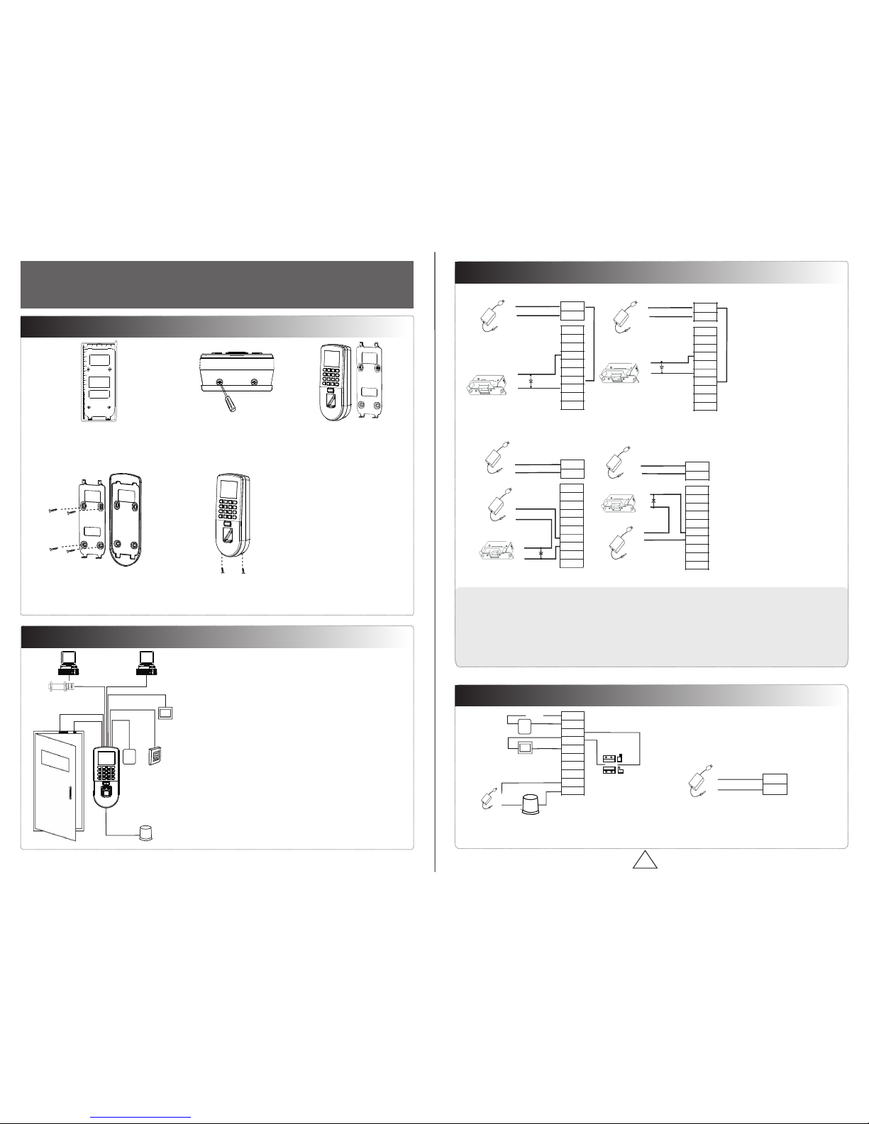
Access Control System Function
(1) If a registered user verified, the device will send a signal
to unlock the door.
(3) If the d llegal , the device will signal the alarm. evice is i ly removed
(4) is External card reader supported.
(5) is External exit button supported.
(7) Supports , communication RS485 TCP/IP to be able to connect with
PC. One PC can manage multiple devices.
(6) External door bell is supported.
①: ‘‘I’: device output current, ‘ ’: lock voltage, ’: lock currentULOCK ILOCK
(1) The system supports NO LOCK and NC LOCK. For example the NO LOCK (normally open at
(2) When the Electrical Lock is connected to the Access control System, you need to connect one FR107
diode parallel with the connection (shipped in the package) in to prevent the self-inductance EMF
power on) is connected with ‘ ‘ ’NO’ and COM terminals, and the NC LOCK(normally close at power
3.Lock Connection
!
WARNING: Do Not operate with Power connected.
(1) Share power with the lock:
ULOCK=12V, I-ILOCK>1A… ①
And the distance between the lock
Device shares power with the lock:
Does not shares power with the lock:
A. =12V I- ≤1A;ULOCK ILOCK
B ≠12V; . ULOCK
C. The distance between the lock and
Alarm Voltage output ≤ DC 12V
4. Other Connections
5. Power Connection
The device working voltage DC 12V, electric current
500mA (50mA standby). Positive is connected with
‘+12V’, negative is connected with ’GND’.
(2) Does not share power with the lock:
2. Structure and Function
Installation Guide
1. Equipm ent Installat ion
NC1
NC1
NC1
NC1
NC1
NO1
NO1
NO1
NO1
NO1
COM1
COM1
COM1
COM1
COM1
NO2
NO2
NO2
NO2
NO2
COM2
COM2
COM2
COM2
COM2
and tighten the screw at the bottom of the unit.
(2) The door sensor will detect the ON-OFF state. If the door
is unexpectedly opened or improperly closed, the alarm signal
(digital value) will be triggered.
the m ounti ng pape r.
on) is connected with ‘NC’and ‘COM’ terminals.
feedback the system. NB: Do not reverse the polarities!
and the device is equal or less
the device is more than 10 meters.
than 10 meters.
* All rights .reserved
1 2 3
4
5
6
7 8 9
0
C
M/OK
Exit
Exit
+Powe r-
(Do not reverse the polarities)
Wiring Hole
Instruction for the M ounti ng Pape r
Stick this mounting pape r to the wa ll or
door frame. Drill the hole s accor ding to
the mounting paper.
Fixing Hole
10
11
12
13
14
15
16
Mountin g Paper
Fixing Hole
Fixing Hole Fixing Hole
DATA1
DATA0
GND
+12V
GLED
RLED
BEEP
Access Control Panel
IP Address:192.168.1.201
Subnet Mask:255.255.255.0
IP Address:192.168.1.124
Subnet Mask:255.255.255.0
Side View Back View
Tamper Switch
Reset Button
About the terminals definition, please refers
to the right table.
RXD Pin3-Txd
TXD Pin2-Rxd
GND Pin5-Gnd
485+ RS485+
485- RS485-
10. Cautions
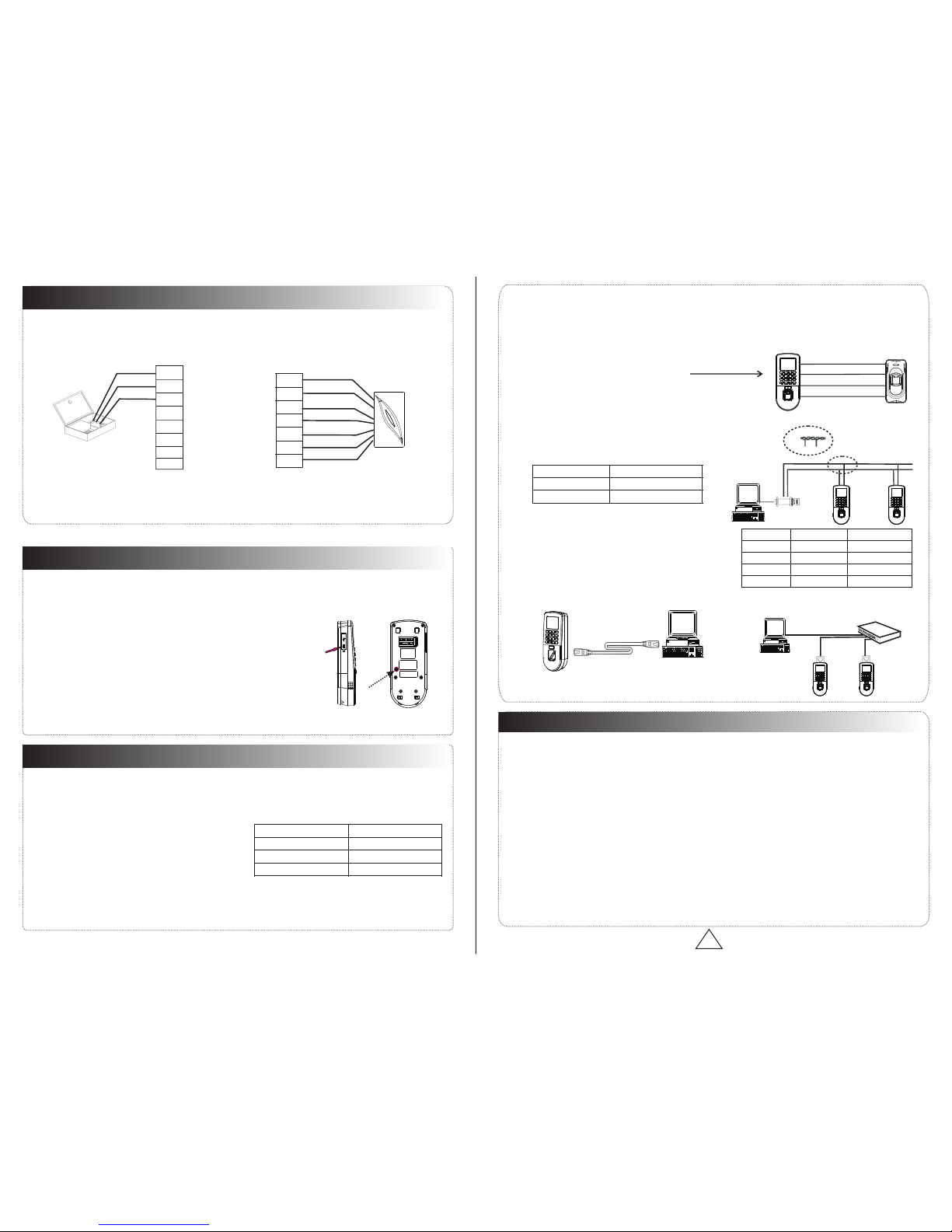
6. Wiegand Output
The device supports standard Wiegand,
26-bit output, so you can connect it with
7. Wiegand Input
connection to a slave card reader. Device are control
The device has a Wiegand input port, which enables the
(In case of long distance installation, use the Wiegand Signal Extender to minimise interference).
(2) To keep a balanced and stable Wiegand signal, connect the device, access control lock and card reader
(1) Do not exceed distance between the Device and Access Control Lock OR Card reader. 90m(meters)
There are three modes that the PC software could communicate and exchange information with the device:
RS485 and TCP/IP, and supports remote control.
9. Communication
8.Other Functions
(1) Manual Reset:
(2) R estor e Fa cto ry Sett ings:
(A) Crossover cable: The device and PC
(B) Straight cable: The device and PC connected
2. TCP/IP Mode:
1. RS485 Mode:
Operation: 30-60 seconds after the tamper alarm has sounded,
other restart it.abnormality, you can use ‘Reset’ function to
If the device does not work properly because of misoperation or
button hole with than 2mm).a sharp tool (the tip diameter is less
Operation: Remove the black rubber cap, then stick the Reset
You can use the tamper switch to restore factory settings, such as
device number, system password, IP address, RS485 address, etc.
press the tamper switch three times.
Terminals PC Serial Ports
Terminals PC Serial Ports
Terminals Wire Name Color
on the same ‘GND’ (ground) port.
devices on both sides of the door to control the access
Please use specified RS485 wire, RS485 active
converter and bus-type wiring.
Terminals:
to LAN/WAN through switch/Lan switch.
connected directly.
various access control devices.
485+
485-
485+ 485-
RS485 Bus
485+ 485- 485+ 485-
RS485
Converter
RJ45-1 TX+ White-orange
RJ45-3 RX+ White-green
RJ45-6 RX- Green
DATA0
GND
DATA1
and electric lock.
The user data won't be cleared.
Two ways for TCP/IP connection:
Switch
PC
…
RJ45- TX Orange2 -
Communications of PC:
Re
ad
e
r
Y
e
l
low
485-
4
8
5
+
P
ur
p
l
e
A
cce
s
s Contro
l De
vi
ce
Re
d
P
o
wer-
Power
+
Blac
k
Diagram of RS485Reader Function (Right)
485+
485-
TXD
RXD
GND
GND
WD0
WD1
IWD1
+12V
BEEP
GLED
RLED
IWD0
GND
1 2 3
4
5
6
7 8 9
0
C
M/OK
1 2 3
4
5
6
7 8 9
0
C
M/OK
1 2 3
4
5
6
7 8 9
0
C
M/OK
1 2 3
4
5
6
7 8 9
0
C
M/OK
1 2 3
4
5
6
7 8 9
0
C
M/OK
* All rights .reserved
!
WARNING: Do Not operate with Power connected.
(1) C onnec t the pow er cabl e af ter a l th e wir ing has b een com plete d. If the d evice i s worki ng
abn ormal ly, plea se s hut d own the d evice , and mak e neces sary ch ecks. P lease n ote tha t any
"HO T SW OP" of wi ring on t he devi ce may da mage th e devic e, and th e warra nty doe s not
cov er dama ge caus ed by imp roper o perat ions.
(2) We re comme nd use th e DC 12V/ 3A power s upply . Pleas e conta ct our te chnic al staf f for d etail s.
(3) P lease r ea d the t ermin al and wi ring de scrip tion an d diagr ams car efull y befor e comme nc ing
wit h insta llati ons. Any d amage t o the dev ice cau sed by im prope r opera tions , wi ll no t be cove red
und er warr anty.
(4) K eep the e xpose d part of w ire les s th an 5m m, to avo id unex pecte d conne ction .
(5) P lease c onnec t the 'GN D' when s tarti ng inst allat ions, e speci ally in a n envir onmen t where s tatic
ele ctric ity is ve ry high .
(6) D o not cha nge the c able ty pe in cas e of a long d istan ce inst allat ions.
Please use specified RS485 wire, RS232/485 active
converter, which consists of bus-type wiring.
you need to parallel a terminal resistance on the receiving
If the communication wire is longer than 100maters,
end, and resistance value is about 120 ohm.
Equ ipmen t suppo rts 485 reade r funct ion, ca n be thro ugh the 4 85com munic ation c onnec ted to
FR1 200 rea der; me anwhi le, it ca n act as Ma ster- slave r which d evice f or m ast er, FR1 200 r eader
for s laver, ach ieve 48 5 Ant i-p assba ck func tions . If sele ct “485 reade r funct ion” , so d evice c an
not c onnec t with PC t hroug h 485 com munic ation s.
RS485Reader:
 Loading...