

ZKTeco C3 Pro + ZKBioSecurity 3.0 Quick Start Manual

Quick Start Guide
C3 Pro
+
ZKBioSecurity 3.0

2
C3 Pro Series Access Control Panels and ZKBioSecurity 3.0 Quick Start Guide
CONTENT
ContentsWhat’s in the Box ......................................................................2
Optional accessories .............................................................. 4
Safety Precautions....................................................................5
Product PIN Diagram .............................................................6
LED Indicators ............................................................................. 7
Product Dimension .................................................................8
Installation of Panel & Cabinet ........................................9
Wiring Legend .........................................................................10
Power Wiring Diagram ..................................................... 11
Without Backup Battery ........................................................ 11
With Backup Battery ............................................................... 11
Wiegand Connection ........................................................ 12
REX Connections .................................................................. 13
Lock Connection .................................................................. 14
Normally Open Lock Powered From Lock Terminal ...... 14
Normally Closed Lock Powered From Lock Terminal .... 14
Switching from Dry to Wet ................................................... 15
Connecting a lock with external power supply ............. 16
Aux. I/O connection .......................................................... 17
Aux. Input Connection .......................................................... 17
Aux. Output Connection ....................................................... 17
Ethernet Connection ........................................................ 18
LAN Connection ...................................................................... 18
Direct connection ................................................................... 18
RS485 Connection .............................................................. 19
Restore factory setting ........................................................... 20
DIP Switch Setting ............................................................... 21
RS485 Address .......................................................................... 21
Terminal Resistance ................................................................ 21
Installation Diagram ............................................................ 22
Troubleshooting ....................................................................23
PC 485 Setting Table .......................................................... 24
Electrical Specifications ...................................................26
Specifications ..........................................................................27
ZKBioSecurity
Software
Installation and
Setup starts at
Page 29

3
C3 Pro Series Access Control Panels and ZKBioSecurity 3.0 Quick Start Guide
What’s in the Box
4 Diode2 Screws & Anchors 2 Screwdriver

4
C3 Pro Series Access Control Panels and ZKBioSecurity 3.0 Quick Start Guide
Optional accessories
Wiegand Card Reader
RS485 Convertor
Alarm
Prox Card
Card Enroller
PTE-1 Exit Button
C3 Pro Cabinet

5
C3 Pro Series Access Control Panels and ZKBioSecurity 3.0 Quick Start Guide
Safety Precautions
The following precautions are to keep user’s safe and prevent any damage.
Please read carefully before installation.
Do not install the device in a place subject to direct sun
light, humidity, dust or soot.
Do not place a magnet near the product. Magnetic objects
such as magnet, CRT, TV, monitor or speaker may damage
the device.
Do not place the device next to heating equipment.
Be careful not to let liquid like water, drinks or chemicals
leak inside the device.
Do not let children touch the device without supervision.
Do not drop or damage the device.
Do not disassemble, repair or alter the device.
Do not use the device for any other purpose than specied.
Clean the device often to remove dust on it. In cleaning, do
not splash water on the device but wipe it out with smooth
cloth or towel.
Contact your supplier in case of a problem.
6
C3 Pro Series Access Control Panels and ZKBioSecurity 3.0 Quick Start Guide
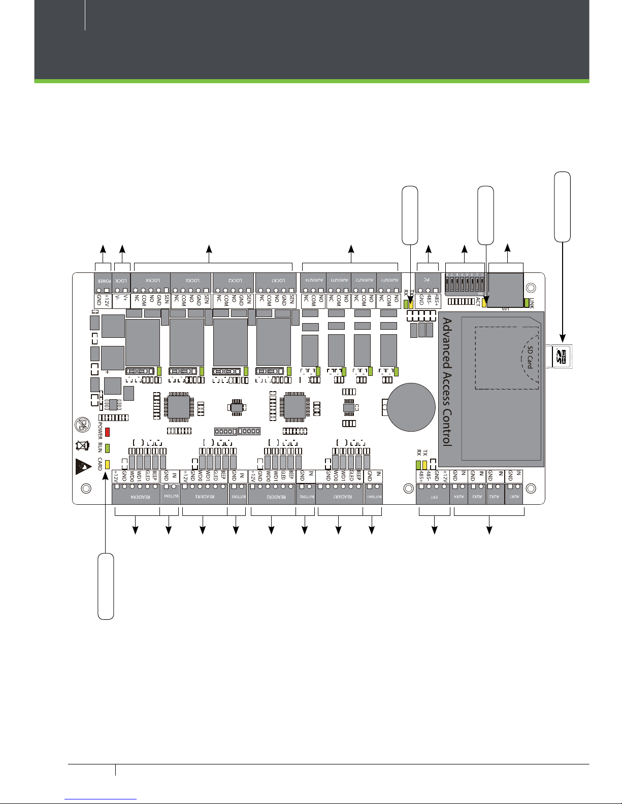
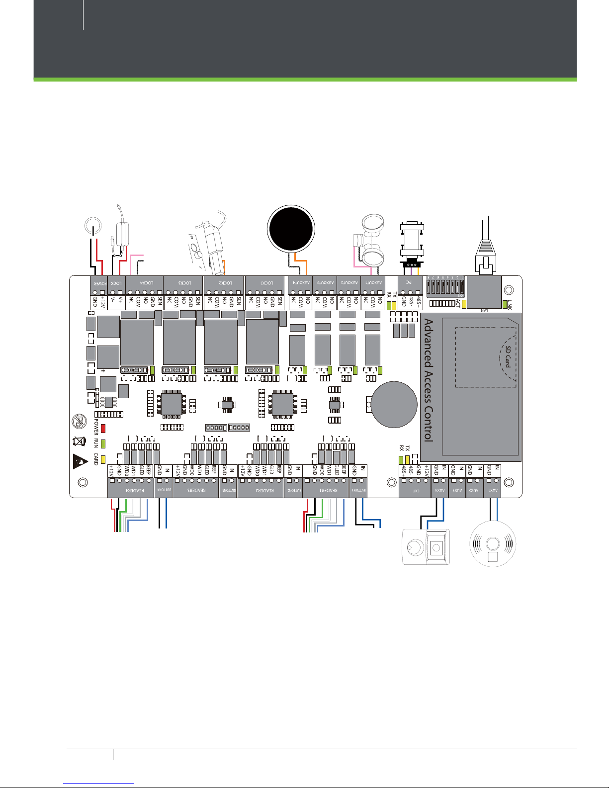
Product PIN Diagram
Figure 1
4 Aux Inputs
Reserved
Lock Power
Power
4 Lock & Door Sensor
4 Aux Output
RS485 Communication
DIP Switches
Ethernet Port
#1 Door Exit Button
#1 Door Card Reader
#2 Door Exit Button
#2 Door Card Reader
#3 Door Exit Button
#3 Door Card Reader
#4 Door Exit Button
#4 Door Card Reader
485 LED
Status LED
ACT LED
SD Card Slot
7
C3 Pro Series Access Control Panels and ZKBioSecurity 3.0 Quick Start Guide
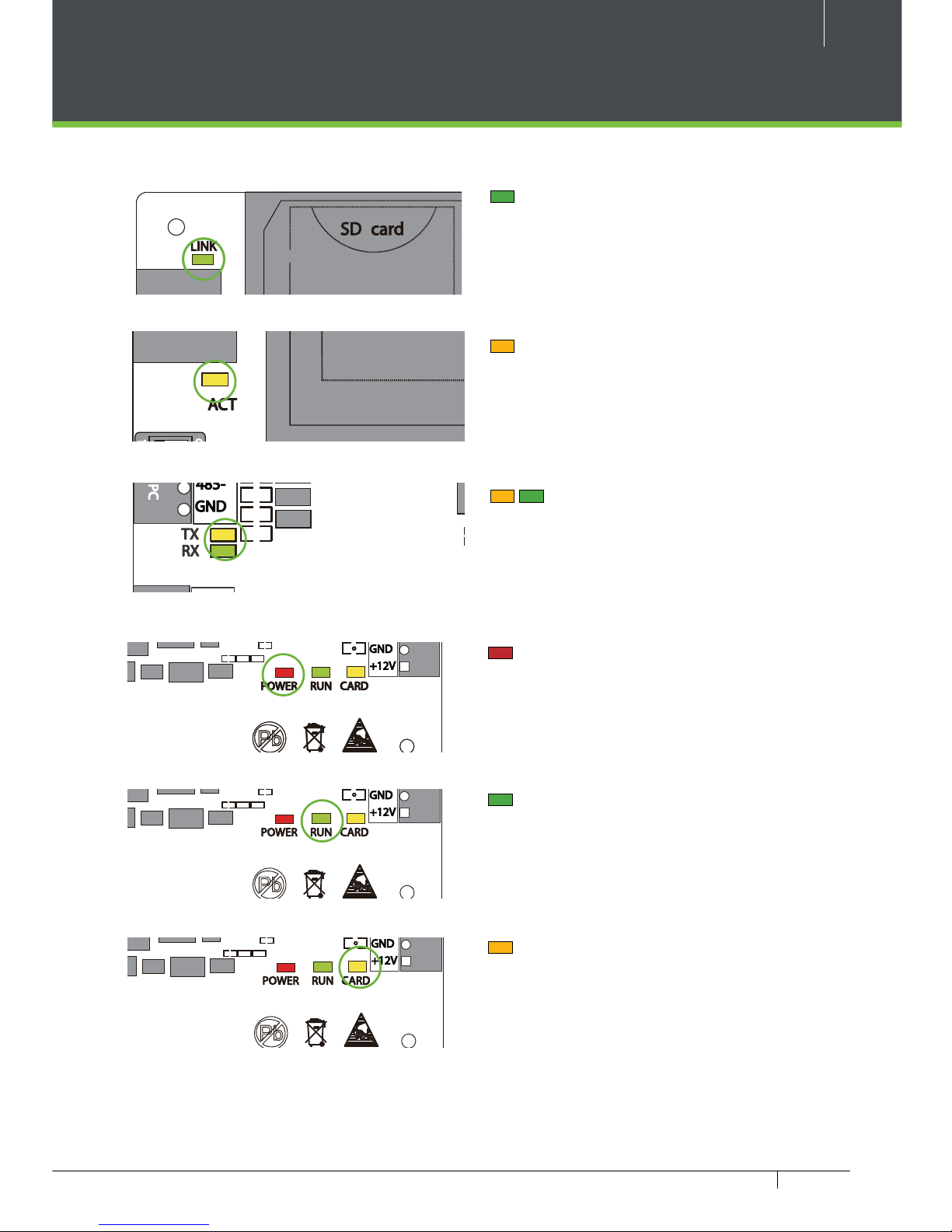
LED Indicators
LINK Solid Green LED indicates TCP/IP
communication is normal.
Flashing (ACT )Yellow LED indicates
data communication is in progress.
EXT RS485 (TX/RX) Flashing Yellow
& Green LED indicates communication is
in progress.
Flashing (POWER) Red LED indicates
the panel is powered on.
Flashing (RUN) Green LED indicates
that panel is in normal working state.
Flashing (CARD) Yellow LED indicates
that the card is read by the panel.
Figure 2
Figure 3
Figure 4
Figure 5
Figure 7
Figure 6
8
C3 Pro Series Access Control Panels and ZKBioSecurity 3.0 Quick Start Guide
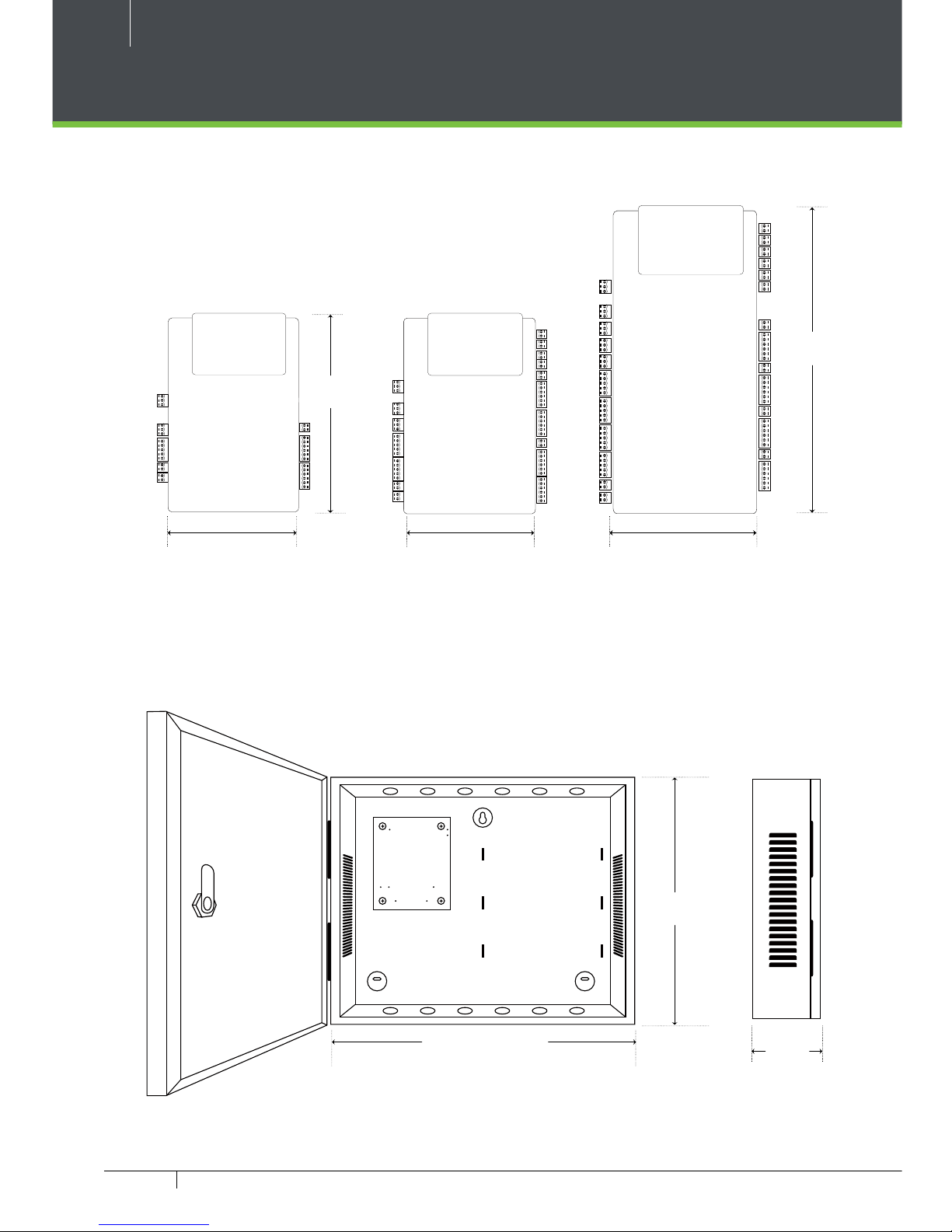
Product Dimension
Figure 9
C3-100 Pro C3-200 Pro C3-400 Pro
C3 Pro- Metal Cabinet
Figure 8
8.00 in
(203.2 mm)
6.325 in
(160.6 mm)
4.17 in (106 mm)
4.17 in (106 mm)
4.17 in (106 mm)
13.625 in (330.2 mm)
11.75 in
(279.4mm)
3.56 in
(90.5 mm)
9
C3 Pro Series Access Control Panels and ZKBioSecurity 3.0 Quick Start Guide
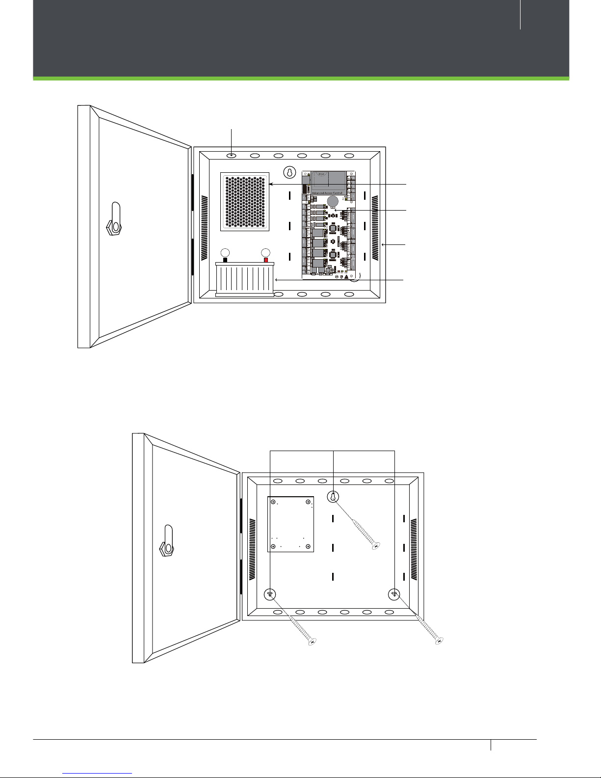
Installation of Panel & Cabinet
+--
Cable Conduit
(Punch Hole for cables)
Mounting Holes
We recommend drilling the mounting plate screws into solid wood (i.e. stud/beam). If a stud/beam cannot be
found, then use the supplied drywall plastic mollies (anchors).
Figure 10
Figure 11
Power Supply
C3 Pro Panel
Heat Dissipation Grill
Backup Battery
10
C3 Pro Series Access Control Panels and ZKBioSecurity 3.0 Quick Start Guide
Wiring Legend
Figure 12
Ethernet Cable
RS
485
485 Convertor
Floodlight
ALARM
Normally Open Lock
12V DC Power Supply
12V DC Power
Normally Close Lock
P
U
S
H
T
O
T
E
S
T
W
E
E
K
L
Y
P
U
S
H
T
O
T
E
S
T
W
E
E
K
L
Y
FIRE
ALARM
Detector
IR Sensor
PTE-1 Exit Button
Card Reader
PTE-1 Exit Button
Card Reader
11
C3 Pro Series Access Control Panels and ZKBioSecurity 3.0 Quick Start Guide
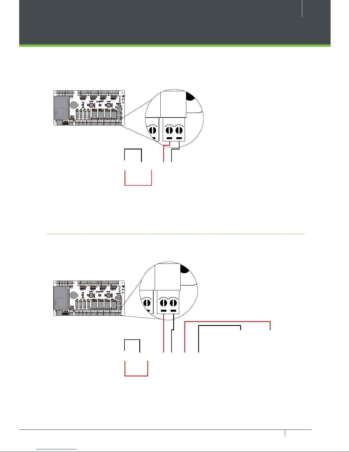
Power Wiring Diagram
Without Backup Battery
With Backup Battery
Switching Power Supply
Ground
Ground
Switching Power Supply
Figure 14
Figure 13
+
+
+
POWER
RUN CARD
V+
V-
12V
GND
GND
+12V
+
+
+
POWER
RUN CARD
V+
V-
12V
GND
GND
+12V
12
C3 Pro Series Access Control Panels and ZKBioSecurity 3.0 Quick Start Guide
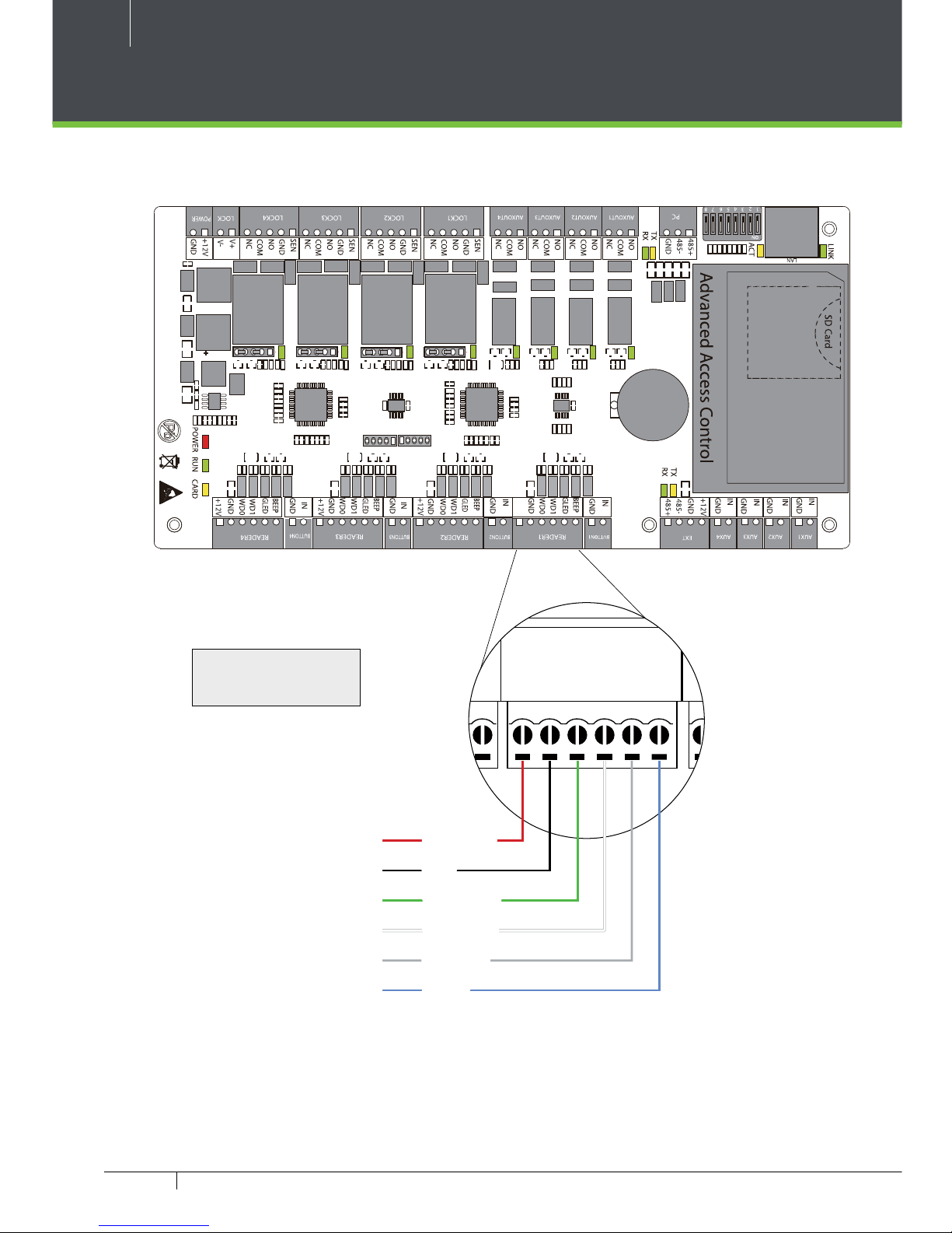
Wiegand Connection
Wiegand Card Reader
Figure 15
16 or 18 AWG shielded
cable recommended
TX
RX
TX
ACT
LINK
RX
AUX 1
IN
GND
IN
GND
IN
GND
IN
GND
+12V
GND
485-
485+
AUX 2 AUX 3 AUX 4 EXT EXT
IN
GND
BEEP
GLED
WD1
WD0
GND
+12V
BUTTON READER
IN
BUTTON READER
NO
COM
NC
485+
485--GND
PC AUXOUT1
NO
COM
NC
AUXOUT2
NO
COM
NC
AUXOUT3
NO
COM
NC
AUXOUT4
12345678
ON
Beeper
Green LED
Wiegand D1
Wiegand D0
GND
DC+(6-14V)
13
C3 Pro Series Access Control Panels and ZKBioSecurity 3.0 Quick Start Guide
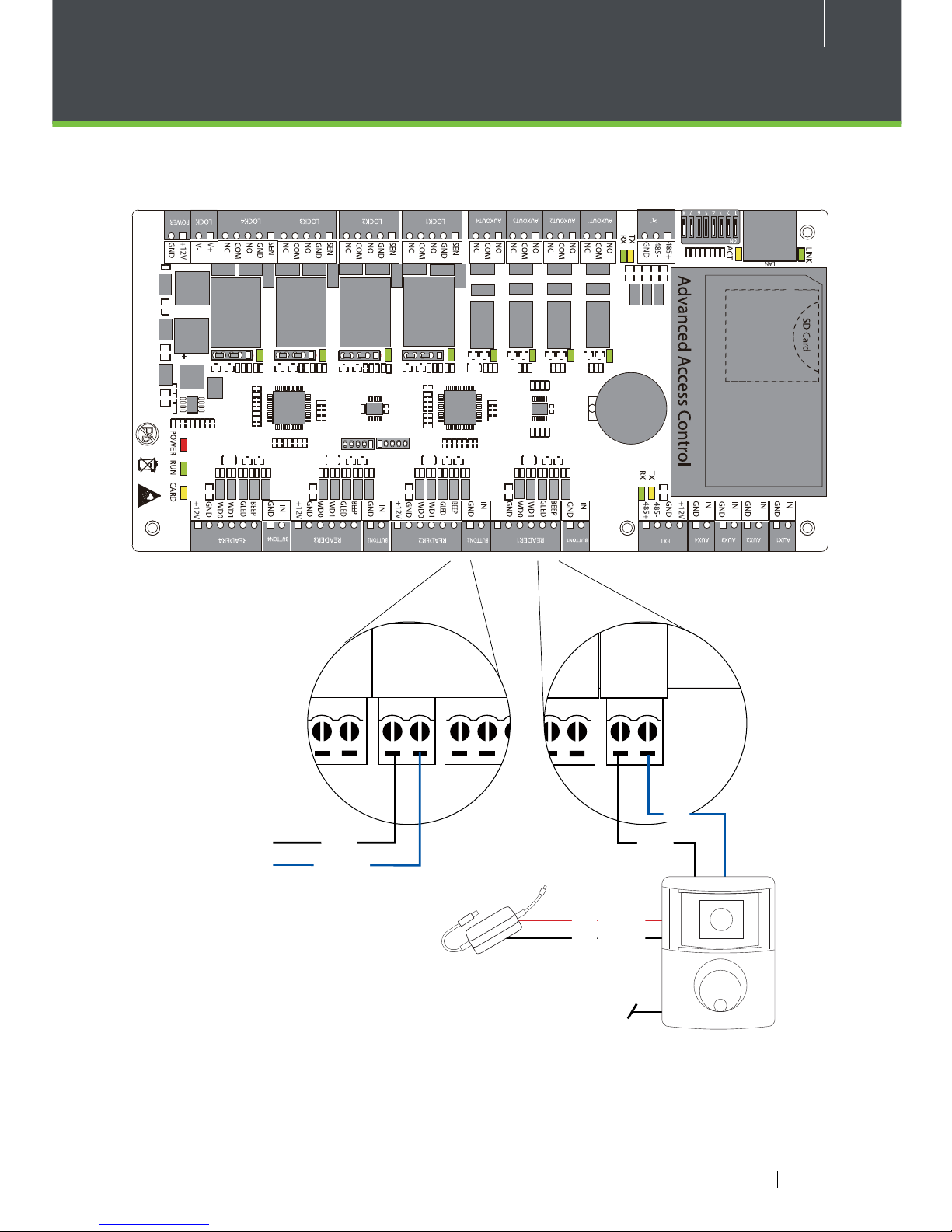
REX Connections
Figure 16
PTE - 1 Exit Button
IR Sensor
Separate Power Supply
TX
RX
TX
ACT
LINK
RX
AUX 1
IN
GND
IN
GND
IN
GND
IN
GND
+12V
GND
485-
485+
AUX 2 AUX 3 AUX 4 EXT EXT
IN
GND
BEEP
GLED
BUTTON READER
NO
COM
NC
485+
485--
GND
PC AUXOUT1
NO
COM
NC
AUXOUT2
AUXOUT3
12345678
ON
Unused
NO
COM
12V DC ( + )
12V DC ( - )
TX
RX
TX
ACT
RX
AUX 1
IN
GND
IN
GND
IN
GND
IN
GND
+12V
GND
485-
485+
AUX 2 AUX 3 AUX 4 EXT EXT
IN
GND
BEEP
GLED
WD1
WD0
GND
+12V
BUTTON READER
IN
GND
BEEP
GLED
BUTTON READER
NO
COM
NC
485+
485--
GND
PC AUXOUT1
NO
COM
NC
AUXOUT2
NO
COM
NC
AUXOUT3
NO
COM
NC
AUXOUT4
SEN
GND
NO
LOCK1
12345678
ON
BUTTON
GND
 Loading...